EP3374545B1 - Saugvorrichtung für spinnmaschinen und spinnmaschine - Google Patents
Saugvorrichtung für spinnmaschinen und spinnmaschine Download PDFInfo
- Publication number
- EP3374545B1 EP3374545B1 EP15832896.3A EP15832896A EP3374545B1 EP 3374545 B1 EP3374545 B1 EP 3374545B1 EP 15832896 A EP15832896 A EP 15832896A EP 3374545 B1 EP3374545 B1 EP 3374545B1
- Authority
- EP
- European Patent Office
- Prior art keywords
- suction
- actuator
- control element
- spinning machine
- suction control
- Prior art date
- Legal status (The legal status is an assumption and is not a legal conclusion. Google has not performed a legal analysis and makes no representation as to the accuracy of the status listed.)
- Active
Links
- 238000009987 spinning Methods 0.000 title claims description 161
- 239000004753 textile Substances 0.000 claims description 114
- 238000005520 cutting process Methods 0.000 claims description 32
- 230000009471 action Effects 0.000 claims description 20
- 230000003213 activating effect Effects 0.000 claims description 7
- 238000011144 upstream manufacturing Methods 0.000 claims description 3
- 230000004913 activation Effects 0.000 claims description 2
- 230000008901 benefit Effects 0.000 description 7
- 239000000463 material Substances 0.000 description 5
- 230000004044 response Effects 0.000 description 4
- 230000000694 effects Effects 0.000 description 3
- 230000003287 optical effect Effects 0.000 description 3
- 238000000034 method Methods 0.000 description 2
- 235000014676 Phragmites communis Nutrition 0.000 description 1
- 238000006243 chemical reaction Methods 0.000 description 1
- 230000008878 coupling Effects 0.000 description 1
- 238000010168 coupling process Methods 0.000 description 1
- 238000005859 coupling reaction Methods 0.000 description 1
- 238000000605 extraction Methods 0.000 description 1
- 238000003780 insertion Methods 0.000 description 1
- 230000037431 insertion Effects 0.000 description 1
- 230000007257 malfunction Effects 0.000 description 1
- 238000004519 manufacturing process Methods 0.000 description 1
- 238000012986 modification Methods 0.000 description 1
- 230000004048 modification Effects 0.000 description 1
- 238000012544 monitoring process Methods 0.000 description 1
- 230000009467 reduction Effects 0.000 description 1
- 238000007378 ring spinning Methods 0.000 description 1
- 230000001360 synchronised effect Effects 0.000 description 1
- 239000002699 waste material Substances 0.000 description 1
- 238000004804 winding Methods 0.000 description 1
Images



Classifications
-
- B—PERFORMING OPERATIONS; TRANSPORTING
- B65—CONVEYING; PACKING; STORING; HANDLING THIN OR FILAMENTARY MATERIAL
- B65H—HANDLING THIN OR FILAMENTARY MATERIAL, e.g. SHEETS, WEBS, CABLES
- B65H63/00—Warning or safety devices, e.g. automatic fault detectors, stop-motions ; Quality control of the package
- B65H63/02—Warning or safety devices, e.g. automatic fault detectors, stop-motions ; Quality control of the package responsive to reduction in material tension, failure of supply, or breakage, of material
- B65H63/024—Warning or safety devices, e.g. automatic fault detectors, stop-motions ; Quality control of the package responsive to reduction in material tension, failure of supply, or breakage, of material responsive to breakage of materials
- B65H63/036—Warning or safety devices, e.g. automatic fault detectors, stop-motions ; Quality control of the package responsive to reduction in material tension, failure of supply, or breakage, of material responsive to breakage of materials characterised by the combination of the detecting or sensing elements with other devices, e.g. stopping devices for material advancing or winding mechanism
-
- B—PERFORMING OPERATIONS; TRANSPORTING
- B65—CONVEYING; PACKING; STORING; HANDLING THIN OR FILAMENTARY MATERIAL
- B65H—HANDLING THIN OR FILAMENTARY MATERIAL, e.g. SHEETS, WEBS, CABLES
- B65H54/00—Winding, coiling, or depositing filamentary material
- B65H54/70—Other constructional features of yarn-winding machines
- B65H54/707—Suction generating system
-
- D—TEXTILES; PAPER
- D01—NATURAL OR MAN-MADE THREADS OR FIBRES; SPINNING
- D01H—SPINNING OR TWISTING
- D01H13/00—Other common constructional features, details or accessories
- D01H13/14—Warning or safety devices, e.g. automatic fault detectors, stop motions ; Monitoring the entanglement of slivers in drafting arrangements
- D01H13/16—Warning or safety devices, e.g. automatic fault detectors, stop motions ; Monitoring the entanglement of slivers in drafting arrangements responsive to reduction in material tension, failure of supply, or breakage, of material
- D01H13/1691—Thread breakage detector means associated with pneumatic cleaning devices, e.g. suction of broken end of yarn
-
- D—TEXTILES; PAPER
- D01—NATURAL OR MAN-MADE THREADS OR FIBRES; SPINNING
- D01H—SPINNING OR TWISTING
- D01H5/00—Drafting machines or arrangements ; Threading of roving into drafting machine
- D01H5/18—Drafting machines or arrangements without fallers or like pinned bars
- D01H5/60—Arrangements maintaining drafting elements free of fibre accumulations
- D01H5/66—Suction devices exclusively
- D01H5/68—Suction end-catchers
-
- B—PERFORMING OPERATIONS; TRANSPORTING
- B65—CONVEYING; PACKING; STORING; HANDLING THIN OR FILAMENTARY MATERIAL
- B65H—HANDLING THIN OR FILAMENTARY MATERIAL, e.g. SHEETS, WEBS, CABLES
- B65H2701/00—Handled material; Storage means
- B65H2701/30—Handled filamentary material
- B65H2701/31—Textiles threads or artificial strands of filaments
Definitions
- the present invention concerns the field of spinning machines, for example the field of ring spinning machines, and concerns a spinning machine comprising an improved suction system, capable of drawing in broken yarn in an advantageous manner.
- the present invention concerns a suction system for spinning machines that is capable of varying its suction power according to the need, in such a way as to guarantee an effective suction action when required while at the same time reducing the drawbacks caused by suction when a suction action is not necessary.
- Figure 1A schematically shows a side sectional view of a spinning machine 1000 according to the state of the art.
- the spinning machine 1000 comprises a supporting structure 1100 that provides a structural support to one or more of the components of the spinning machine 1000 that are described below.
- the supporting structure 1100 serves the function of a housing or frame for the spinning machine 1000.
- the spinning machine 1000 comprises at least two pairs of rollers 1201, 1202 and 1203, 1204, respectively.
- Figure 1A shows three pairs of rollers 1201 and 1202, 1203 and 1204, 1205 and 1206, as this at least one first roller is motor driven, while the second roller is driven and set moving by the first roller.
- the first roller 1201 can be motor driven so that it moves in the direction indicated by the arrow located inside it, while the second roller 1202 is driven by the friction generated through contact with the first roller 1201.
- the rollers 1201-1206, as well as the respective motors (not illustrated) and/or means for transmitting motion from the motors to the rollers (not illustrated) can be supported by the supporting structure 1100.
- At least two of the pairs of rollers 1201 and 1202, 1203 and 1204, 1205 and 1206 rotate at different speeds.
- the pair of rollers 1205 and 1206 can rotate at a higher speed than the pair of rollers 1203 and 1204.
- the first textile element 1301 Due to the difference in the rotation speeds of the pairs of rollers, the first textile element 1301 is stretched and then, when leaving the rollers, it is twisted so that it winds on itself and becomes stronger and more resistant, and then it is wound on the second collection element 1304.
- the spinning machine may contain, and generally contains, a plurality of spinning points 1200. Spinning machines with hundreds or more than a thousand spinning points are common. In these cases, each spinning point 1200 is associated with a first collection element 1303 and a second collection element 1304. For the sake of clarity, in the description of the present invention reference is made to only one spinning point 1200.
- suction may be different at the various suction openings 1401 and this does not guarantee that the textile elements 1301, 1302 are drawn in after being torn.
- Inadequate suction may cause a blockage in the suction pipes 1403 and the suction openings 1401.
- Spinning machines comprising suction ducts according to the prior art are further known from documents CH 699 713 A2 , GB 2 156 391 , FR 2 794 137 A1 and DE 35 15677 .
- the present invention is based on the general concept that the spinning machine 1000 does not need a constant suction action at the level of the opening 1401. On the contrary, it is sufficient to provide a suction action at the level of the opening 1401 at the moment when the first or the second textile element 1301, 1302 tears up. Since the tearing of the textile element 1301, 1302 is a relatively infrequent event, it is possible to avoid providing a constant suction action at the suction opening 1401 for most of the time, on condition that it is possible to guarantee a suction action at the level of the suction opening 1401 in the presence of a tear.
- the object of the invention is solved by a suction device according to claims 1 to 8 and a spinning machine according to claims 9 to 12.
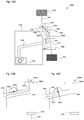
- Figure 2A schematically shows a side sectional view of a spinning machine 2000 and of a corresponding suction device according to a first embodiment which does not belong to the present invention.
- the spinning machine 2000 differs from the known spinning machine 1000 thanks to the presence of a suction control element 2404.
- the suction control element 2404 can be made in any way suited to partially or completely reduce suction at the opening 1401 of the suction pipe 1403.
- the suction control element 2404 is preferably a butterfly valve, however the present invention is not limited to this solution, as can be seen here below.
- such an embodiment makes it possible to regulate the suction power at the opening 1401 in a controlled manner.
- the suction control element 2404 partially or completely limits the suction power at the opening 1401.
- the valve is partially or completely closed, as shown in Figure 2C . Thanks to the closed configuration, the power necessary to maintain a negative pressure inside the suction pipe is reduced. In other words, the power consumed by the suction element 1402 is reduced thanks to the presence of the suction control element 2404.
- the suction control element 2404 When a tear is produced, the suction control element 2404 is activated in such a way as to increase the suction action at the opening 1401, preferably to the maximum level. In other words, the suction control element 2404 is partially or completely opened, as shown in Figure 2B .
- a spinning machine 2000 for spinning a textile element 1301, 1302 comprising: a spinning point 1200 for spinning the textile element; a suction device 1401, 1402, 1403 comprising the suction element 1402, the suction opening 1401 in proximity to the textile element 1301, 1302, and the suction pipe 1403 suited to connect the suction element 1402 to the suction opening 1401; a suction control element 2404 suited to be set at least in an open configuration and in a closed configuration, wherein in the open configuration the suction control element 2404 allows the suction element 1402 to draw through the suction opening 1401 and in the closed configuration the suction control element 2404 prevents the suction element 1402 from drawing in through the suction opening 1401; and an actuator 2405 suited to operate the suction control element 2404, configured in such a way as to set the suction control element in the open configuration in the presence of at least one tear in the textile element and to set the suction control element 2404 in the closed configuration when there are no tears in the textile element
- open configuration can mean both a completely open configuration, as shown in Figure 2B , and a partially open configuration.
- closed configuration can mean both a completely closed configuration, as shown in Figure 2C , and a partially closed configuration. Furthermore, it is possible for the closed configuration not to be completely closed, due to tolerances generated during the production of the suction control element 2404, which in any case allow a minimum quantity of air to flow in even in the configuration defined as completely closed.
- the present invention makes it possible to ascertain the presence or the absence of a tear in the textile element 1301, 1302 are described here below.
- the present invention can be implemented through any method that makes it possible to ascertain the presence of a tear and to consequently regulate the actuator 2405 of the suction control element 2404 in such a way as to reduce suction, preferably to zero, at the opening 1401 when no tears are present, and to increase, preferably to the maximum possible value, the suction power at the opening 1401 in the presence of a tear.
- the opening 1401 may be located downstream of the last pair of rollers 1205, 1206, the present invention is not limited to this configuration.
- the opening 1401 may be located in a lower or higher position.
- the opening 1401 may be located at the level of the last pair of rollers 1205, 1206, or between the pair of rollers 1205, 1206 and the pair of rollers 1203, 1204, as schematically shown in Figure 9A .
- the opening 1401 may be located in any position that allows the textile element with the tear to be drawn, so as to prevent the textile element 1301, 1302 from being wound on one or more rollers 1201-1206.
- the opening 1401 is located downstream of the last pair of rollers 1205, 1206 in such a way as to draw in the textile element with the tear and prevent the textile element 1301, 1302 from being wound on one or more rollers 1201-1206.
- the suction control element 2404 is located on the suction pipe 1403, in proximity to the opening 1401.
- This configuration offers the advantage that at the moment when the suction control element 2404 is operated in order to increase the suction power at the opening 1401, the power increase takes place very quickly, preferably immediately, as the portion of the suction pipe 1403 between the suction control element 2404 and the opening 1401 is limited.
- the present invention is not limited to this case and the suction control element 2404 may be positioned on any point of the suction pipe 1403.
- this embodiment makes it possible to obtain a spinning machine 2000, in which in the closed configuration the suction control element 2404 partially or completely prevents the suction element 1402 from drawing through the suction opening 1401.
- the suction control element 2404 is obtained through a butterfly valve and a rotary actuator 2405.
- the present invention is not limited to this configuration and other types of valve, for example a ball valve, or a gate valve, or other known types of valve, can be used.
- the present embodiment makes it possible to maintain, at a given instant, most of the suction closing elements 2404 provided on the various spindles of the spinning machine 2000 in a partially or completely closed configuration, in such a way as to partially or completely reduce the suction action at the openings 1401 corresponding to the various spinning points 1200.
- the openings 1401 corresponding to the spinning points 1200 where a tear has been produced will benefit from a suitable suction action so as to recover the broken part of the textile element, thanks to the proper operation of the suction control element 2404.
- a spinning machine 2000 having, for example, hundreds of spinning points 1200, at a given instant only part of the spinning points 1200 will have a tear and will consequently be provided with suitable suction power for drawing the torn textile element, if necessary with the maximum suction power. This makes it possible to limit the power consumption of the suction element 1402.
- the suction elements 1402 of the spinning points where there are no tears will consume less power, thanks to the fact that the suction control element 2404 is partially or completely closed.
- the single suction element 1402 in the case where a single suction element 1402 is provided for all of the spinning points 1200, for example through a connection to a plurality of suction pipes 1403, the single suction element 1402 will consume less power as, at least in part of the spinning points 1200, the suction control element 2404 limits the suction action in the respective spinning point, and consequently limits the respective power consumption.
- the single suction element 1402 in the case where a single suction element 1402 is used for the plurality of spinning points, considering that statistically only part of the spinning points 1200 will have a tear, the single suction element 1402 can be sized in such a way as to provide enough suction power to produce a suction action on a smaller number of spinning points compared to the total number of spinning points installed on the spinning machine, thus reducing the energy costs, the overall dimensions and the noisiness of the suction element 1402. For example, if statistically only 5% of the spinning points has a tear at every instant, the single suction element 1402 can be sized in such a way as to provide enough suction power for 5%-10% of the total spinning points.
- Figure 3A schematically shows a side sectional view of a spinning machine 3000 and of a corresponding suction device according to a second embodiment which does not belong to the present invention.
- suction control element 3404 has been described as a potentiometer connected to the power supply of the suction element 1402, the present invention is not limited to this embodiment.
- other methods for controlling the power of the suction element 1402 can be implemented, such as, for example, voltage control, or control through a PWM controller, or similar electronic controls suited to control the power supplied to the suction element 1402.
- a suction control element 3404 may be associated with each suction element 1402 present in the spinning machine and it may be operated by a sum or combination of the values obtained from the actuators corresponding to each individual spinning point 1200.
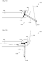
- Figure 4A schematically shows a side sectional view of elements of a spinning machine 4000 and of a corresponding suction device according to a third embodiment which belongs to the present invention.
- Figures 4B and C schematically show a front view and a top view, respectively, of the embodiment illustrated in Figure 4A.
- Figure 4D schematically shows the operation of the embodiment illustrated in Figure 4A .
- the spinning machine 4000 is based on the spinning machine 2000 and differs from the latter exactly in the execution of the actuator 2405, which is shown only schematically in the spinning machine 2000 and is the actuator 4405 in the spinning machine 4000.
- the actuator 4405 is a mechanical actuator, mechanically connected to the suction control element 2404. Consequently, a movement of the actuator 4405 will cause a movement of the suction control element 2404.
- the actuator 4405 comprises four elements 4405A, 4405B, 4405C and 4405D.
- the element 4405A is a rotation axis for the actuator 4405 and for the suction control element 2404.
- the rotation axis 4405A penetrates inside the suction pipe 1403 in such a way as to allow the suction control element 2404 and the actuator 4405 to be integrally connected to each other.
- the elements 4405B and 4405C are extension arms that allow the rotation axis 4405A to be connected to the element 4405D.
- the shape of the extension arms is not limited to that illustrated in the figure, but alternatively other shapes allowing the operation of the actuator 4405 can be implemented, as described below.
- a single, curved or linear extension arm may be provided between the elements 4405A and 4405D.
- the element 4405D is a feeler. When the textile element 1301, 1302 is continuous, meaning with no tears, as shown in Figures 4A, 4B and 4C , the feeler 4405D is maintained in the position illustrated in the three figures by the second textile element 1302.
- the feeler 4405D tends to move downwards, following an angular movement caused by the rotation axis 4405A.
- the feeler 4405D cannot move in this direction and remains locked in the position illustrated in Figures 4A, 4B and 4C .
- the feeler 4405D thus maintains the actuator 4405 in the illustrated position, which results in the closure of the suction control element 2404, as shown in Figure 4A .
- the suction control element may be maintained in a partially closed configuration.
- the power required to create a negative pressure inside the suction pipe 1403 is thus limited, preferably considerably reduced thanks to the partial or, as shown, complete limitation of the suction action obtained by means of the suction control element 2404.
- the feeler 4405D is no longer maintained in position by the textile element, as shown in Figure 4A . Being moved downwards by the weight of the feeler 4405D and/or by the weight of the actuator 4405, and/or by the weight of the suction control element 2404, possibly asymmetrical, the actuator 4405 performs a clockwise rotation that results in the partial or complete opening of the suction control element 2404, as shown in Figure 4D .
- the suction control element 2404 allows the connection between the inside of the suction pipe 1403 and the opening 1401. Thanks to the movement of the suction control element 2404, the torn textile element is drawn into the suction pipe 1403, as illustrated.
- the suction control element 2404 may be made in an asymmetrical manner in order to cause a rotation moment of the actuator.
- the half of the valve in the upper position in Figure 4A could be constructed so that it is heavier than the half of the valve in the lower position in Figure 4A .
- This solution offers the advantage that the actuator does not need to be constructed with such a weight as to be able, alone, to operate the valve or, more generally, the suction control element 2404.
- the actuator 4405 has been described as having a specific shape, the present invention should not be considered as limited to the described shape. More generally, it is possible to use any shape of the actuator that, in combination with the shape of the suction control element 2404, generates an angular or linear moment: an angular moment in the case of a suction control element 2404 with angular movement, such as a butterfly valve, or a linear moment in the case of a suction control element 2404 with linear movement, such as a gate valve.
- the actuator 4405 of the embodiment illustrated has been described in combination with a suction control element 2404 corresponding to a butterfly valve, the present invention is not limited to this solution. As an alternative, the actuator 4405 can be combined with any form of suction control element 2404 described in the present invention.
- the actuator 4405 can be combined with any form of the suction control element 3404 previously described.
- the actuator can act on a mechanical portion of the suction control element 3404, for example a mechanical control suited to regulate a potentiometer or a PWM controller.
- the actuator 4405 can furthermore act on a potentiometer or any other element that makes it possible to convert a mechanical signal into an electronic signal, and the resulting electronic signal can be used to control the suction control element 3404.
- the actuator 4405 is advantageous as it positions the feeler on the side of the textile element 1301, 1302 opposite the opening 1401. This position is advantageous, as the feeler 4405D cannot be accidentally pushed downwards by the movement of the textile element, causing the undesired opening of the suction control element 2404.
- the feeler 4405D is on the side of the textile element corresponding to the side of the opening 1401, the movement of the textile element may cause the feeler to be pushed downwards, causing the undesired opening of the suction control element 2404.
- FIG. 5A schematically shows a side sectional view of elements of a spinning machine 5000 and of a corresponding suction device according to a fourth embodiment which belongs to the present invention, analogously to that which is shown in Figure 4A .
- Figures 5B and 5C schematically show a front view and a top view, respectively, of the embodiment of Figure 5A , analogously to that which is shown in Figures 4B and 5B .
- the spinning machine 5000 is based on the spinning machine 4000 and differs from the latter due to the presence of the actuator 5405 that replaces the actuator 4405.
- the actuator 5405 differs from the actuator 4405 in that the extension arms 4405B, 4405C are not present on both sides of the actuator 5405, differently from the actuator 4405.
- the extension arms are present on one side only, on the left in Figure 5B and at the bottom in Figure 5C .
- the shape of the actuator makes it possible to position the textile element with respect to the feeler 4405D at any moment.
- the advantage offered by the actuator 4405 compared to the actuator 5404 lies in that, even in the presence of considerable movements of the textile element 1301, 1302, the textile element cannot move out of the area delimited by the elements 4405B, 4405C and 4405D. Nevertheless, in the actuator 4405 this possible drawback can be mitigated by designing the feeler 4405D in a suitable shape. For example, a particularly long feeler 4405D reduces the risk of the textile element moving from behind the feeler 4405D. Alternatively, as shown in Figure 5D , a feeler 5405D in the shape of a U open on the side of the element 4405C reduces in a similar manner the risk of the textile element moving from its seat with respect to the feeler 4405D illustrated in Figure 5C .
- the actuator 5405 can be used both with the suction control element 2404 and with the suction control element 3404.
- Figure 6A schematically shows a side sectional view of elements of a spinning machine 6000 and of a respective suction device according to a fifth embodiment which belongs to the present invention, analogously to that which is shown in Figure 4A .
- Figures 6B and 6C schematically show a front view and a top view, respectively, of the embodiment shown in Figure 6A , analogously to that which is shown in Figures 4B and 4C .
- Figure 6D schematically shows the operation of the embodiment of Figure 6A , analogously to that which is shown in Figure 4D .
- the spinning machine 6000 is based on the spinning machine 4000, from which it differs as the actuator 4405 is replaced by the actuator 6405.
- the actuator 6405 corresponds to the actuator 4405, to which at least one adjustable stop element 6501 and 6502 is added.
- the stop element 6502 prevents the actuator 6405 from moving further in the anticlockwise direction with respect to the stop position illustrated in Figure 6A
- the stop element 6501 prevents the actuator 6405 from moving further in the clockwise direction with respect to the stop position illustrated in Figure 6D .
- the two stop elements 6501 and 6502 illustrated depend on the specific shape of the actuator, and that different stop elements are possible in the case of a different embodiment, for example, of the extension arms 4405B and 4405C.
- the adjustable stop elements 6501, 6502 it is possible to limit the movement of the actuator 6405 within a predetermined area. In the case of an angular actuator like the one illustrated, within a predetermined angular area. This is an advantage, as it prevents undesired movements of the actuator which instead may result in unexpected movements of the spinning machine.
- the textile element 1301, 1302 drawn in in Figure 4D may get stuck in the suction control element 2404 and cause the same to rotate on itself, in the clockwise direction, moving it back to the closed configuration and reducing the suction effect. Thanks to the presence of the stop elements 6501, 6502 such a risk of malfunction is avoided.
- the position of at least one of the stop elements 6501, 6502 is adjustable, for example through an adjusting screw or other adjusting systems. Thanks to this adjustment, it is possible to control the maximum degree to which the suction control element 2404 can be opened and closed. For example, if the stop element 6502 is located more leftwards with respect to the position illustrated in Figure 6A , if there are no tears it is possible to ensure that the suction control element 2404 remains only partially closed, and not completely closed as illustrated in the figure. Analogously, the complete or partial opening can be ensured by controlling the position of the stop element 6501.
- the actuator 6405 is based on the actuator 4405, the present embodiment is not limited to this case and the actuator 6405 could be based also on the actuator 5405, or on other actuators described in the present invention. Furthermore, as in the case of the actuator 4405, the actuator 6405 can be used both with the suction control element 2404 and with the suction control element 3404.
- Figure 7A schematically shows a side sectional view of a spinning machine 7000 and of a respective suction device according to a sixth embodiment which does not belong to the present invention.
- Figures 7B and 7C schematically show an enlarged view and the operation of part of the embodiment illustrated in Figure 7A .
- the spinning machine 7000 is based on the spinning machine 2000 and differs from the spinning machines 4000-6000 in that the actuator 2405 is not constituted by the mechanical actuators 4405-6405, but by an electromechanical actuator 7405, preferably an electromagnet.
- the electromechanical actuator 7405 is illustrated only schematically, as different specific embodiments are possible, such as, for example, an electromagnet, an AC motor, a DC motor, a stepping motor, a pneumatic or hydraulic motor, or other solutions that make it possible to mechanically activate the suction control element 2404 through the actuator 7405 based on an electric signal, possibly converted by a motor or compressor in the case of a pneumatic or hydraulic actuator.
- the spinning machine 7000 comprises also a sensor 7601 suited to monitor the presence of the textile element. Even if in the figure the sensor 7601 is arranged in such a way as to monitor the presence of the second textile element 1302 in proximity to the second collection element 1304, the present invention is not limited to this configuration and the sensor 7601 can be placed in any position that allows the presence of the first or of the second textile element 1301, 1302 to be monitored.
- the sensor 7601 is also connected with the actuator 7405 of the suction control element 2404 through a connection (not illustrated herein). Thanks to such a connection, it is possible to control the actuator with the electric signal emitted by the sensor 7601.
- the connection can be wired or wireless.
- the actuator 7405 will be controlled in such a way as to maintain the suction control element in the closed configuration.
- the signal emitted by the sensor causes the actuator 7405 to move, so as to set the suction control element in the open configuration, as illustrated, and to cause the textile element with the tear to be drawn in.
- This embodiment is particularly advantageous, as it makes it possible to avoid a mechanical contact with the textile element 1301, 1302, and is thus particularly suitable for the cases where the mechanical contact required by the mechanical actuators 4405, 5405, 6405 is not possible. Furthermore, thanks to the electrical connection between the sensor 7601 and the actuator 7405, it is possible to position these two elements with a high degree of flexibility.
- the present embodiment is not limited to this case, and the actuator 7405 can be used both with the suction control element 2404 and with the suction control element 3404. Even more advantageously, it is possible to connect the sensor 7601 directly to the suction control element 3404, in such a way as to allow a completely electronic control of the suction power, which does not require any mechanical movements.
Landscapes
- Engineering & Computer Science (AREA)
- Textile Engineering (AREA)
- Mechanical Engineering (AREA)
- Quality & Reliability (AREA)
- Spinning Or Twisting Of Yarns (AREA)
Claims (12)
- Saugvorrichtung für eine Spinnmaschine zum Spinnen eines textilen Elements (1301, 1302), Folgendes umfassend:- eine Ansaugöffnung (1401), dazu geeignet, in der Nähe des textilen Elements (1301, 1302) positioniert zu werden;- ein Saugsteuerelement (2404, 11404), dazu geeignet, wenigstens in eine offene und in eine geschlossene Konfiguration versetzt zu werden;- einen Aktuator (2405, 4405, 5405, 6405, 7405, 11405, 12405), dazu geeignet, das Saugsteuerelement (2404, 11404) zu betätigen, dazu konfiguriert, das Saugsteuerelement in die offene Konfiguration zu versetzen, wenn wenigstens ein Riss in dem textilen Element vorhanden ist, und das Saugsteuerelement (2404, 11404) in die geschlossene Konfiguration zu versetzen, wenn keine Risse in dem textilen Element vorhanden sind,wobei der Aktuator (2405, 4405, 5405, 6405, 11405, 12405) ein mechanischer Aktuator (2405, 4405, 5405, 6405, 11405, 12405) ist, wobei der Aktuator (2405, 4405, 5405, 6405, 11405, 12405) einen Fühler (4405D, 5405D, 11405D) umfasst, wobei bei Fehlen von Rissen in dem textilen Element (1301, 1302) der Fühler (4405D, 5405D, 11405D) an das textile Element (1301, 1302) anliegend gehalten wird und damit die Bewegung des Aktuators (2405, 4405, 5405, 6405, 11405,12405) verhindert wird, dadurch gekennzeichnet, dass der Fühler (4405D, 5405D, 11405D) an der Seite des textilen Elements (1301, 1302) positioniert ist, die der Ansaugöffnung (1401) entgegengesetzt ist.
- Saugvorrichtung nach Patentanspruch 1, wobei das Saugsteuerelement (2404, 11404) in der geschlossenen Konfiguration die Ansaugung durch ein Saugelement (1402) durch die Ansaugöffnung (1401) vollständig verhindert, oder wobei das Saugsteuerelement (2404, 11404) in der geschlossenen Konfiguration eine Öffnung (12902) bildet, die eine reduzierte Saugwirkung erlaubt.
- Saugvorrichtung nach Patentanspruch 1 oder 2, wobei das Saugsteuerelement (2404, 11404) ein Ventil ist, vorzugsweise eine Drosselklappe oder ein Kugelventil oder ein Absperrventil.
- Saugvorrichtung nach Patentanspruch 1, wobei der Fühler (4405D, 5405D, 11405D) durch eine Kraft, die durch das Gewicht des Aktuators (2405, 4405, 5405, 6405, 11405, 12405) erzeugt wird und/oder durch eine Kraft, die durch das Gewicht des Saugsteuerelements ((2404, 11404) erzeugt wird, an das textile Element (1301, 1302) anliegend gehalten wird.
- Saugvorrichtung nach Patentanspruch 4, wobei das Saugsteuerelement (2404, 11404) asymmetrisch ausgeführt ist, um eine Kraft auszuüben, die eine Drehung des Aktuators (2405,4405, 5405, 6405, 11405, 12405) bewirkt.
- Saugvorrichtung nach einem jeglichen der Patentansprüche von 1 bis 5, wobei der Aktuator (6405, 12405) wenigstens ein verstellbares Anschlagelement (6501, 6502, 12501, 12502) umfasst, dazu geeignet, die Bewegung des Aktuators (6405, 12405) innerhalb eines vorbestimmten Bereichs zu begrenzen.
- Saugvorrichtung nach einem jeden der vorstehenden Patentansprüche, des Weiteren wenigstens ein stromaufwärts des Saugsteuerelements (2404, 11404) positioniertes Ansaugloch (12901) umfassend.
- Saugvorrichtung nach einem jeden der vorstehenden Patentansprüche, wobei die Spinnmaschine oder die Saugvorrichtung des Weiteren eine Warnleuchte (9902) umfasst, wobei die Warnleuchte so konfiguriert ist, dass sie aufleuchtet, wenn das Saugsteuerelement (2404, 11404) in die im Wesentlichen offene Konfiguration versetzt ist.
- Spinnmaschine, wenigstens einen Spinnpunkt (1200) zum Spinnen eines textilen Elements und eine Saugvorrichtung nach einem jeden der vorstehenden Patentansprüche umfassend.
- Spinnmaschine nach Patentanspruch 9, wobei die Spinnmaschine des Weiteren Folgendes umfasst:- ein Schneidelement (8701), dazu geeignet, das textile Element (1301, 1302) zu schneiden; und- einen Aktuator (8702), dazu geeignet, das Schneidelement (8701) zu betätigen.
- Spinnmaschine nach Patentanspruch 10, wobei- der Aktuator (8702) zur Aktivierung des Schneidelements (8701) durch den Aktuator (2405, 4405, 5405, 6405, 11405, 12405) zur Aktivierung des Saugsteuerelements (2404, 11404) aktiviert wird, oder wobei- der Aktuator (8702) zur Aktivierung des Schneidelements (8701) und der Aktuator (2405, 4405, 5405, 6405, 11405, 12405) zur Aktivierung des Saugsteuerelements (2404, 11404) ein einziger Aktuator sind.
- Spinnmaschine nach Patentanspruch 10, wobei der Aktuator (7405) zur Aktivierung des Saugsteuerelements (2404, 11404) dazu konfiguriert ist, das Saugsteuerelement nach einer vorbestimmten Zeit ab der Aktivierung des Schneidelements durch den Aktuator (8702) zur Aktivierung des Schneidelements (8701) in die geschlossene Konfiguration zu versetzen.
Applications Claiming Priority (1)
| Application Number | Priority Date | Filing Date | Title |
|---|---|---|---|
| PCT/IT2015/000275 WO2017081707A1 (en) | 2015-11-10 | 2015-11-10 | Suction device for spinning machines |
Publications (2)
| Publication Number | Publication Date |
|---|---|
| EP3374545A1 EP3374545A1 (de) | 2018-09-19 |
| EP3374545B1 true EP3374545B1 (de) | 2020-01-15 |
Family
ID=55346158
Family Applications (1)
| Application Number | Title | Priority Date | Filing Date |
|---|---|---|---|
| EP15832896.3A Active EP3374545B1 (de) | 2015-11-10 | 2015-11-10 | Saugvorrichtung für spinnmaschinen und spinnmaschine |
Country Status (3)
| Country | Link |
|---|---|
| EP (1) | EP3374545B1 (de) |
| CN (1) | CN108603310B (de) |
| WO (1) | WO2017081707A1 (de) |
Families Citing this family (1)
| Publication number | Priority date | Publication date | Assignee | Title |
|---|---|---|---|---|
| DE102019116224A1 (de) * | 2019-06-14 | 2020-12-17 | Maschinenfabrik Rieter Ag | Verfahren zum Betreiben einer Absaugvorrichtung einer Textilmaschine, sowie eine Absaugvorrichtung und eine Textilmaschine |
Family Cites Families (8)
| Publication number | Priority date | Publication date | Assignee | Title |
|---|---|---|---|---|
| DE3410471A1 (de) * | 1984-03-22 | 1985-09-26 | Fritz 7347 Bad Überkingen Stahlecker | Oe-friktionsspinnmaschine mit einer vielzahl von spinnaggregaten und einem verfahrbaren wartungsgeraet |
| DE3515677A1 (de) * | 1985-05-02 | 1986-11-06 | Zinser Textilmaschinen Gmbh, 7333 Ebersbach | Spinnmaschine |
| FR2794137B1 (fr) * | 1999-05-31 | 2001-07-27 | Schlumberger Cie N | Tete d'etirage pour machines d'etirage pourvue d'un dispositif d'obturation automatique de conduits pneumatiques |
| JP2005171476A (ja) * | 2003-12-11 | 2005-06-30 | Mas Fab Rieter Ag | 精紡位置のための吸込みシステムを備えた精紡機の運転法及び精紡位置のための吸込みシステムを備えた精紡機 |
| CH699713A2 (de) * | 2008-10-13 | 2010-04-15 | Rieter Ag Maschf | Spinnmaschine mit Fadenabsaugeinrichtung. |
| ATE557121T1 (de) * | 2009-03-23 | 2012-05-15 | Rieter Ag Maschf | Spinnmaschine mit fadenabsaugeinrichtung |
| CN103147181B (zh) * | 2011-12-07 | 2017-09-15 | 里特机械公司 | 纺纱机上的抽吸设备 |
| CN204625888U (zh) * | 2015-02-16 | 2015-09-09 | 河北宏润新型面料有限公司 | 一种细纱游动吹吸风装置 |
-
2015
- 2015-11-10 WO PCT/IT2015/000275 patent/WO2017081707A1/en not_active Ceased
- 2015-11-10 EP EP15832896.3A patent/EP3374545B1/de active Active
- 2015-11-10 CN CN201580084470.3A patent/CN108603310B/zh not_active Expired - Fee Related
Non-Patent Citations (1)
| Title |
|---|
| None * |
Also Published As
| Publication number | Publication date |
|---|---|
| CN108603310A (zh) | 2018-09-28 |
| CN108603310B (zh) | 2021-10-08 |
| WO2017081707A1 (en) | 2017-05-18 |
| EP3374545A1 (de) | 2018-09-19 |
Similar Documents
| Publication | Publication Date | Title |
|---|---|---|
| CN104562328B (zh) | 纺纱机和外部电源故障时操作该纺纱机的方法 | |
| JP6346272B2 (ja) | 糸回収装置及び前記糸回収装置を備えた糸供給システム | |
| JP4821644B2 (ja) | 紡績機械 | |
| CN101418493B (zh) | 电脑针织横编机的剪夹纱装置 | |
| JP7300315B2 (ja) | 繊維機械の動作状態を決定する方法、および、繊維機械 | |
| EP2829647B1 (de) | Garnzuführvorrichtung mit Schussfaden-Wickeltrommel und feedbackgesteuerter Schussfaden-Bremsvorrichtung | |
| US20110113831A1 (en) | Method and knitting machine for producing a knitted product from substantially untwisted fibre material | |
| CN107310984A (zh) | 一种纺织机械用不停机连续缠绕线装置 | |
| EP3374545A1 (de) | Saugvorrichtung für spinnmaschinen | |
| CN106087142B (zh) | 倍捻机或并捻机的锭子运行方法和相应的倍捻机或并捻机 | |
| EP2985371B1 (de) | Spinnmaschine | |
| CN204080336U (zh) | 一种经编机积极送纱纱架 | |
| EP2966020B1 (de) | Garnspeichervorrichtung, garnwickeleinheit und garnwickelmaschine | |
| CN109563657A (zh) | 针织织带机和相应的织造方法 | |
| WO2017081573A2 (en) | Suction control system for spinning frames | |
| CN114955668A (zh) | 一种调节结构及纺织机械用卷筒 | |
| CN201305724Y (zh) | 电脑针织横编机的剪夹纱装置 | |
| JP4974027B2 (ja) | ワープ直線式編機糸ガイドの糸通し改良装置 | |
| CN103966782B (zh) | 刺绣机底线断线自动感应装置及自动停机方法 | |
| CN203513888U (zh) | 加弹机的导丝盘缠丝自停装置 | |
| EP3458632B1 (de) | Vermischungsvorrichtung und zugehöriges verfahren | |
| JP6569551B2 (ja) | 精紡機におけるニューマチッククリアラ装置の制御方法 | |
| CN212834275U (zh) | 雪尼尔纱线机的控制系统 | |
| CN210085713U (zh) | 一种经编机的放卷装置 | |
| KR100944478B1 (ko) | 해권장치 |
Legal Events
| Date | Code | Title | Description |
|---|---|---|---|
| STAA | Information on the status of an ep patent application or granted ep patent |
Free format text: STATUS: THE INTERNATIONAL PUBLICATION HAS BEEN MADE |
|
| PUAI | Public reference made under article 153(3) epc to a published international application that has entered the european phase |
Free format text: ORIGINAL CODE: 0009012 |
|
| STAA | Information on the status of an ep patent application or granted ep patent |
Free format text: STATUS: REQUEST FOR EXAMINATION WAS MADE |
|
| 17P | Request for examination filed |
Effective date: 20180525 |
|
| AK | Designated contracting states |
Kind code of ref document: A1 Designated state(s): AL AT BE BG CH CY CZ DE DK EE ES FI FR GB GR HR HU IE IS IT LI LT LU LV MC MK MT NL NO PL PT RO RS SE SI SK SM TR |
|
| AX | Request for extension of the european patent |
Extension state: BA ME |
|
| DAV | Request for validation of the european patent (deleted) | ||
| DAX | Request for extension of the european patent (deleted) | ||
| GRAP | Despatch of communication of intention to grant a patent |
Free format text: ORIGINAL CODE: EPIDOSNIGR1 |
|
| STAA | Information on the status of an ep patent application or granted ep patent |
Free format text: STATUS: GRANT OF PATENT IS INTENDED |
|
| INTG | Intention to grant announced |
Effective date: 20190322 |
|
| GRAJ | Information related to disapproval of communication of intention to grant by the applicant or resumption of examination proceedings by the epo deleted |
Free format text: ORIGINAL CODE: EPIDOSDIGR1 |
|
| STAA | Information on the status of an ep patent application or granted ep patent |
Free format text: STATUS: REQUEST FOR EXAMINATION WAS MADE |
|
| INTC | Intention to grant announced (deleted) | ||
| GRAS | Grant fee paid |
Free format text: ORIGINAL CODE: EPIDOSNIGR3 |
|
| STAA | Information on the status of an ep patent application or granted ep patent |
Free format text: STATUS: GRANT OF PATENT IS INTENDED |
|
| GRAP | Despatch of communication of intention to grant a patent |
Free format text: ORIGINAL CODE: EPIDOSNIGR1 |
|
| INTG | Intention to grant announced |
Effective date: 20190911 |
|
| GRAA | (expected) grant |
Free format text: ORIGINAL CODE: 0009210 |
|
| STAA | Information on the status of an ep patent application or granted ep patent |
Free format text: STATUS: THE PATENT HAS BEEN GRANTED |
|
| AK | Designated contracting states |
Kind code of ref document: B1 Designated state(s): AL AT BE BG CH CY CZ DE DK EE ES FI FR GB GR HR HU IE IS IT LI LT LU LV MC MK MT NL NO PL PT RO RS SE SI SK SM TR |
|
| REG | Reference to a national code |
Ref country code: CH Ref legal event code: EP Ref country code: GB Ref legal event code: FG4D |
|
| REG | Reference to a national code |
Ref country code: IE Ref legal event code: FG4D |
|
| REG | Reference to a national code |
Ref country code: DE Ref legal event code: R096 Ref document number: 602015045750 Country of ref document: DE |
|
| REG | Reference to a national code |
Ref country code: AT Ref legal event code: REF Ref document number: 1225227 Country of ref document: AT Kind code of ref document: T Effective date: 20200215 |
|
| REG | Reference to a national code |
Ref country code: CH Ref legal event code: NV Representative=s name: SEDIN SA, CH |
|
| REG | Reference to a national code |
Ref country code: NL Ref legal event code: MP Effective date: 20200115 |
|
| REG | Reference to a national code |
Ref country code: LT Ref legal event code: MG4D |
|
| PG25 | Lapsed in a contracting state [announced via postgrant information from national office to epo] |
Ref country code: NO Free format text: LAPSE BECAUSE OF FAILURE TO SUBMIT A TRANSLATION OF THE DESCRIPTION OR TO PAY THE FEE WITHIN THE PRESCRIBED TIME-LIMIT Effective date: 20200415 Ref country code: NL Free format text: LAPSE BECAUSE OF FAILURE TO SUBMIT A TRANSLATION OF THE DESCRIPTION OR TO PAY THE FEE WITHIN THE PRESCRIBED TIME-LIMIT Effective date: 20200115 Ref country code: RS Free format text: LAPSE BECAUSE OF FAILURE TO SUBMIT A TRANSLATION OF THE DESCRIPTION OR TO PAY THE FEE WITHIN THE PRESCRIBED TIME-LIMIT Effective date: 20200115 Ref country code: PT Free format text: LAPSE BECAUSE OF FAILURE TO SUBMIT A TRANSLATION OF THE DESCRIPTION OR TO PAY THE FEE WITHIN THE PRESCRIBED TIME-LIMIT Effective date: 20200607 Ref country code: FI Free format text: LAPSE BECAUSE OF FAILURE TO SUBMIT A TRANSLATION OF THE DESCRIPTION OR TO PAY THE FEE WITHIN THE PRESCRIBED TIME-LIMIT Effective date: 20200115 |
|
| PG25 | Lapsed in a contracting state [announced via postgrant information from national office to epo] |
Ref country code: IS Free format text: LAPSE BECAUSE OF FAILURE TO SUBMIT A TRANSLATION OF THE DESCRIPTION OR TO PAY THE FEE WITHIN THE PRESCRIBED TIME-LIMIT Effective date: 20200515 Ref country code: GR Free format text: LAPSE BECAUSE OF FAILURE TO SUBMIT A TRANSLATION OF THE DESCRIPTION OR TO PAY THE FEE WITHIN THE PRESCRIBED TIME-LIMIT Effective date: 20200416 Ref country code: HR Free format text: LAPSE BECAUSE OF FAILURE TO SUBMIT A TRANSLATION OF THE DESCRIPTION OR TO PAY THE FEE WITHIN THE PRESCRIBED TIME-LIMIT Effective date: 20200115 Ref country code: LV Free format text: LAPSE BECAUSE OF FAILURE TO SUBMIT A TRANSLATION OF THE DESCRIPTION OR TO PAY THE FEE WITHIN THE PRESCRIBED TIME-LIMIT Effective date: 20200115 Ref country code: SE Free format text: LAPSE BECAUSE OF FAILURE TO SUBMIT A TRANSLATION OF THE DESCRIPTION OR TO PAY THE FEE WITHIN THE PRESCRIBED TIME-LIMIT Effective date: 20200115 Ref country code: BG Free format text: LAPSE BECAUSE OF FAILURE TO SUBMIT A TRANSLATION OF THE DESCRIPTION OR TO PAY THE FEE WITHIN THE PRESCRIBED TIME-LIMIT Effective date: 20200415 |
|
| REG | Reference to a national code |
Ref country code: DE Ref legal event code: R097 Ref document number: 602015045750 Country of ref document: DE |
|
| PG25 | Lapsed in a contracting state [announced via postgrant information from national office to epo] |
Ref country code: ES Free format text: LAPSE BECAUSE OF FAILURE TO SUBMIT A TRANSLATION OF THE DESCRIPTION OR TO PAY THE FEE WITHIN THE PRESCRIBED TIME-LIMIT Effective date: 20200115 Ref country code: DK Free format text: LAPSE BECAUSE OF FAILURE TO SUBMIT A TRANSLATION OF THE DESCRIPTION OR TO PAY THE FEE WITHIN THE PRESCRIBED TIME-LIMIT Effective date: 20200115 Ref country code: LT Free format text: LAPSE BECAUSE OF FAILURE TO SUBMIT A TRANSLATION OF THE DESCRIPTION OR TO PAY THE FEE WITHIN THE PRESCRIBED TIME-LIMIT Effective date: 20200115 Ref country code: EE Free format text: LAPSE BECAUSE OF FAILURE TO SUBMIT A TRANSLATION OF THE DESCRIPTION OR TO PAY THE FEE WITHIN THE PRESCRIBED TIME-LIMIT Effective date: 20200115 Ref country code: RO Free format text: LAPSE BECAUSE OF FAILURE TO SUBMIT A TRANSLATION OF THE DESCRIPTION OR TO PAY THE FEE WITHIN THE PRESCRIBED TIME-LIMIT Effective date: 20200115 Ref country code: CZ Free format text: LAPSE BECAUSE OF FAILURE TO SUBMIT A TRANSLATION OF THE DESCRIPTION OR TO PAY THE FEE WITHIN THE PRESCRIBED TIME-LIMIT Effective date: 20200115 Ref country code: SK Free format text: LAPSE BECAUSE OF FAILURE TO SUBMIT A TRANSLATION OF THE DESCRIPTION OR TO PAY THE FEE WITHIN THE PRESCRIBED TIME-LIMIT Effective date: 20200115 Ref country code: SM Free format text: LAPSE BECAUSE OF FAILURE TO SUBMIT A TRANSLATION OF THE DESCRIPTION OR TO PAY THE FEE WITHIN THE PRESCRIBED TIME-LIMIT Effective date: 20200115 |
|
| REG | Reference to a national code |
Ref country code: AT Ref legal event code: MK05 Ref document number: 1225227 Country of ref document: AT Kind code of ref document: T Effective date: 20200115 |
|
| PLBE | No opposition filed within time limit |
Free format text: ORIGINAL CODE: 0009261 |
|
| STAA | Information on the status of an ep patent application or granted ep patent |
Free format text: STATUS: NO OPPOSITION FILED WITHIN TIME LIMIT |
|
| 26N | No opposition filed |
Effective date: 20201016 |
|
| PG25 | Lapsed in a contracting state [announced via postgrant information from national office to epo] |
Ref country code: AT Free format text: LAPSE BECAUSE OF FAILURE TO SUBMIT A TRANSLATION OF THE DESCRIPTION OR TO PAY THE FEE WITHIN THE PRESCRIBED TIME-LIMIT Effective date: 20200115 |
|
| PG25 | Lapsed in a contracting state [announced via postgrant information from national office to epo] |
Ref country code: SI Free format text: LAPSE BECAUSE OF FAILURE TO SUBMIT A TRANSLATION OF THE DESCRIPTION OR TO PAY THE FEE WITHIN THE PRESCRIBED TIME-LIMIT Effective date: 20200115 Ref country code: PL Free format text: LAPSE BECAUSE OF FAILURE TO SUBMIT A TRANSLATION OF THE DESCRIPTION OR TO PAY THE FEE WITHIN THE PRESCRIBED TIME-LIMIT Effective date: 20200115 |
|
| PG25 | Lapsed in a contracting state [announced via postgrant information from national office to epo] |
Ref country code: MC Free format text: LAPSE BECAUSE OF FAILURE TO SUBMIT A TRANSLATION OF THE DESCRIPTION OR TO PAY THE FEE WITHIN THE PRESCRIBED TIME-LIMIT Effective date: 20200115 |
|
| GBPC | Gb: european patent ceased through non-payment of renewal fee |
Effective date: 20201110 |
|
| PG25 | Lapsed in a contracting state [announced via postgrant information from national office to epo] |
Ref country code: LU Free format text: LAPSE BECAUSE OF NON-PAYMENT OF DUE FEES Effective date: 20201110 |
|
| REG | Reference to a national code |
Ref country code: BE Ref legal event code: MM Effective date: 20201130 |
|
| PG25 | Lapsed in a contracting state [announced via postgrant information from national office to epo] |
Ref country code: FR Free format text: LAPSE BECAUSE OF NON-PAYMENT OF DUE FEES Effective date: 20201130 Ref country code: IE Free format text: LAPSE BECAUSE OF NON-PAYMENT OF DUE FEES Effective date: 20201110 |
|
| PG25 | Lapsed in a contracting state [announced via postgrant information from national office to epo] |
Ref country code: GB Free format text: LAPSE BECAUSE OF NON-PAYMENT OF DUE FEES Effective date: 20201110 |
|
| PG25 | Lapsed in a contracting state [announced via postgrant information from national office to epo] |
Ref country code: MT Free format text: LAPSE BECAUSE OF FAILURE TO SUBMIT A TRANSLATION OF THE DESCRIPTION OR TO PAY THE FEE WITHIN THE PRESCRIBED TIME-LIMIT Effective date: 20200115 Ref country code: CY Free format text: LAPSE BECAUSE OF FAILURE TO SUBMIT A TRANSLATION OF THE DESCRIPTION OR TO PAY THE FEE WITHIN THE PRESCRIBED TIME-LIMIT Effective date: 20200115 |
|
| PG25 | Lapsed in a contracting state [announced via postgrant information from national office to epo] |
Ref country code: MK Free format text: LAPSE BECAUSE OF FAILURE TO SUBMIT A TRANSLATION OF THE DESCRIPTION OR TO PAY THE FEE WITHIN THE PRESCRIBED TIME-LIMIT Effective date: 20200115 Ref country code: AL Free format text: LAPSE BECAUSE OF FAILURE TO SUBMIT A TRANSLATION OF THE DESCRIPTION OR TO PAY THE FEE WITHIN THE PRESCRIBED TIME-LIMIT Effective date: 20200115 |
|
| PG25 | Lapsed in a contracting state [announced via postgrant information from national office to epo] |
Ref country code: BE Free format text: LAPSE BECAUSE OF NON-PAYMENT OF DUE FEES Effective date: 20201130 |
|
| PGFP | Annual fee paid to national office [announced via postgrant information from national office to epo] |
Ref country code: TR Payment date: 20221027 Year of fee payment: 8 Ref country code: IT Payment date: 20221019 Year of fee payment: 8 Ref country code: DE Payment date: 20221025 Year of fee payment: 8 |
|
| PGFP | Annual fee paid to national office [announced via postgrant information from national office to epo] |
Ref country code: CH Payment date: 20221103 Year of fee payment: 8 |
|
| REG | Reference to a national code |
Ref country code: DE Ref legal event code: R119 Ref document number: 602015045750 Country of ref document: DE |
|
| REG | Reference to a national code |
Ref country code: CH Ref legal event code: PL |
|
| PG25 | Lapsed in a contracting state [announced via postgrant information from national office to epo] |
Ref country code: CH Free format text: LAPSE BECAUSE OF NON-PAYMENT OF DUE FEES Effective date: 20231130 |
|
| PG25 | Lapsed in a contracting state [announced via postgrant information from national office to epo] |
Ref country code: CH Free format text: LAPSE BECAUSE OF NON-PAYMENT OF DUE FEES Effective date: 20231130 |
|
| PG25 | Lapsed in a contracting state [announced via postgrant information from national office to epo] |
Ref country code: DE Free format text: LAPSE BECAUSE OF NON-PAYMENT OF DUE FEES Effective date: 20240601 |
|
| PG25 | Lapsed in a contracting state [announced via postgrant information from national office to epo] |
Ref country code: DE Free format text: LAPSE BECAUSE OF NON-PAYMENT OF DUE FEES Effective date: 20240601 |
|
| PG25 | Lapsed in a contracting state [announced via postgrant information from national office to epo] |
Ref country code: IT Free format text: LAPSE BECAUSE OF NON-PAYMENT OF DUE FEES Effective date: 20231110 |
|
| PG25 | Lapsed in a contracting state [announced via postgrant information from national office to epo] |
Ref country code: IT Free format text: LAPSE BECAUSE OF NON-PAYMENT OF DUE FEES Effective date: 20231110 |