EP3374643B1 - Délestage de palier axial dans des machines de traitement de fluide - Google Patents
Délestage de palier axial dans des machines de traitement de fluide Download PDFInfo
- Publication number
- EP3374643B1 EP3374643B1 EP16784932.2A EP16784932A EP3374643B1 EP 3374643 B1 EP3374643 B1 EP 3374643B1 EP 16784932 A EP16784932 A EP 16784932A EP 3374643 B1 EP3374643 B1 EP 3374643B1
- Authority
- EP
- European Patent Office
- Prior art keywords
- fluid
- pressure
- impellers
- barrier
- thrust disk
- Prior art date
- Legal status (The legal status is an assumption and is not a legal conclusion. Google has not performed a legal analysis and makes no representation as to the accuracy of the status listed.)
- Active
Links
Images



Classifications
-
- F—MECHANICAL ENGINEERING; LIGHTING; HEATING; WEAPONS; BLASTING
- F04—POSITIVE - DISPLACEMENT MACHINES FOR LIQUIDS; PUMPS FOR LIQUIDS OR ELASTIC FLUIDS
- F04D—NON-POSITIVE-DISPLACEMENT PUMPS
- F04D29/00—Details, component parts, or accessories
- F04D29/05—Shafts or bearings, or assemblies thereof, specially adapted for elastic fluid pumps
- F04D29/051—Axial thrust balancing
-
- F—MECHANICAL ENGINEERING; LIGHTING; HEATING; WEAPONS; BLASTING
- F04—POSITIVE - DISPLACEMENT MACHINES FOR LIQUIDS; PUMPS FOR LIQUIDS OR ELASTIC FLUIDS
- F04D—NON-POSITIVE-DISPLACEMENT PUMPS
- F04D13/00—Pumping installations or systems
- F04D13/02—Units comprising pumps and their driving means
- F04D13/06—Units comprising pumps and their driving means the pump being electrically driven
- F04D13/08—Units comprising pumps and their driving means the pump being electrically driven for submerged use
- F04D13/086—Units comprising pumps and their driving means the pump being electrically driven for submerged use the pump and drive motor are both submerged
-
- F—MECHANICAL ENGINEERING; LIGHTING; HEATING; WEAPONS; BLASTING
- F04—POSITIVE - DISPLACEMENT MACHINES FOR LIQUIDS; PUMPS FOR LIQUIDS OR ELASTIC FLUIDS
- F04D—NON-POSITIVE-DISPLACEMENT PUMPS
- F04D13/00—Pumping installations or systems
- F04D13/02—Units comprising pumps and their driving means
- F04D13/06—Units comprising pumps and their driving means the pump being electrically driven
- F04D13/08—Units comprising pumps and their driving means the pump being electrically driven for submerged use
- F04D13/10—Units comprising pumps and their driving means the pump being electrically driven for submerged use adapted for use in mining bore holes
-
- F—MECHANICAL ENGINEERING; LIGHTING; HEATING; WEAPONS; BLASTING
- F04—POSITIVE - DISPLACEMENT MACHINES FOR LIQUIDS; PUMPS FOR LIQUIDS OR ELASTIC FLUIDS
- F04D—NON-POSITIVE-DISPLACEMENT PUMPS
- F04D13/00—Pumping installations or systems
- F04D13/12—Combinations of two or more pumps
-
- F—MECHANICAL ENGINEERING; LIGHTING; HEATING; WEAPONS; BLASTING
- F04—POSITIVE - DISPLACEMENT MACHINES FOR LIQUIDS; PUMPS FOR LIQUIDS OR ELASTIC FLUIDS
- F04D—NON-POSITIVE-DISPLACEMENT PUMPS
- F04D19/00—Axial-flow pumps
- F04D19/02—Multi-stage pumps
- F04D19/024—Multi-stage pumps with contrarotating parts
-
- F—MECHANICAL ENGINEERING; LIGHTING; HEATING; WEAPONS; BLASTING
- F04—POSITIVE - DISPLACEMENT MACHINES FOR LIQUIDS; PUMPS FOR LIQUIDS OR ELASTIC FLUIDS
- F04D—NON-POSITIVE-DISPLACEMENT PUMPS
- F04D25/00—Pumping installations or systems
- F04D25/02—Units comprising pumps and their driving means
- F04D25/06—Units comprising pumps and their driving means the pump being electrically driven
- F04D25/0686—Units comprising pumps and their driving means the pump being electrically driven specially adapted for submerged use
-
- F—MECHANICAL ENGINEERING; LIGHTING; HEATING; WEAPONS; BLASTING
- F04—POSITIVE - DISPLACEMENT MACHINES FOR LIQUIDS; PUMPS FOR LIQUIDS OR ELASTIC FLUIDS
- F04D—NON-POSITIVE-DISPLACEMENT PUMPS
- F04D29/00—Details, component parts, or accessories
- F04D29/04—Shafts or bearings, or assemblies thereof
- F04D29/041—Axial thrust balancing
- F04D29/0416—Axial thrust balancing balancing pistons
-
- F—MECHANICAL ENGINEERING; LIGHTING; HEATING; WEAPONS; BLASTING
- F04—POSITIVE - DISPLACEMENT MACHINES FOR LIQUIDS; PUMPS FOR LIQUIDS OR ELASTIC FLUIDS
- F04D—NON-POSITIVE-DISPLACEMENT PUMPS
- F04D29/00—Details, component parts, or accessories
- F04D29/05—Shafts or bearings, or assemblies thereof, specially adapted for elastic fluid pumps
- F04D29/051—Axial thrust balancing
- F04D29/0516—Axial thrust balancing balancing pistons
-
- F—MECHANICAL ENGINEERING; LIGHTING; HEATING; WEAPONS; BLASTING
- F04—POSITIVE - DISPLACEMENT MACHINES FOR LIQUIDS; PUMPS FOR LIQUIDS OR ELASTIC FLUIDS
- F04D—NON-POSITIVE-DISPLACEMENT PUMPS
- F04D29/00—Details, component parts, or accessories
- F04D29/08—Sealings
- F04D29/10—Shaft sealings
- F04D29/102—Shaft sealings especially adapted for elastic fluid pumps
- F04D29/104—Shaft sealings especially adapted for elastic fluid pumps the sealing fluid being other than the working fluid or being the working fluid treated
-
- F—MECHANICAL ENGINEERING; LIGHTING; HEATING; WEAPONS; BLASTING
- F04—POSITIVE - DISPLACEMENT MACHINES FOR LIQUIDS; PUMPS FOR LIQUIDS OR ELASTIC FLUIDS
- F04D—NON-POSITIVE-DISPLACEMENT PUMPS
- F04D29/00—Details, component parts, or accessories
- F04D29/08—Sealings
- F04D29/10—Shaft sealings
- F04D29/106—Shaft sealings especially adapted for liquid pumps
- F04D29/108—Shaft sealings especially adapted for liquid pumps the sealing fluid being other than the working liquid or being the working liquid treated
Definitions
- the present disclosure relates to subsea fluid processing machines. More particularly, the present disclosure relates to techniques for offloading a thrust bearing in rotating fluid processing machines such as subsea pumps and compressors.
- Known turbo compressors and pumps generate a differential pressure across one or more impeller stages attached to a rotating shaft.
- the generated differential pressure acts on the impeller and shaft arrangement, creating a thrust force in the axial direction pointing from the discharge end towards the suction end.
- An axial thrust bearing is normally attached to the shaft to counteract this thrust force and keep the shaft in a stable position during various operating and load conditions.
- a differential pressure is created across a balancing piston arranged such that both ends of the shaft arrangement are exposed to a similar pressure that can be either the suction or discharge pressure.
- the balancing piston and shaft areas are exposed to the pressure so as to more or less balance, or counteract, the thrust force.
- Normally such an arrangement is combined with a smaller thrust bearing to counteract the thrust force that may be un-balanced under some conditions.
- balance piston arrangements as described involve tight clearances that are exposed to the process medium. Therefore, balance piston arrangements may not be well suited in applications where the process medium is not a clean single phase fluid. Examples include where the process medium contains wear particles, such as sand or other solid particles, or where phase changes may occur in the process fluid such as the formation of ice or hydrates. In such cases the tight clearances of the balancing piston may be at risk of wear, partially blocking and/or fully blocking which would jeopardize the intended function of the balance piston.
- An axial thrust bearing can be designed to compensate the entire thrust force without the use of a balance piston.
- Such bearings may have to be very large and therefore suffer from disadvantages such as: (1) large associated frictional losses; (2) adverse effects on shaft rotor dynamics; (3) utilization of large amounts of space; and (4) substantial increases to the overall system weight.
- the size of the axial thrust bearing required may constrain the effective differential pressure that can be provided by the turbo compressor or pump.
- US 3960245 describes a high-pressure compressor comprising chambers and passages connected thereto for conveying a sealing and lubricating liquid to and from the impeller shaft.
- WO 2014/054440 describes a centrifugal compressor comprising a rotor with an impeller mounted thereon attached to a casing and a labyrinth seal attached to the casing and disposed to face the rotor.
- US 5256038 describes a canned motor pump in which an external supply of cooling and lubricating fluid is circulated through the motor. An internal seal arrangement is provided for restricting flow between the motor and the pump.
- the present invention resides in a fluid pressure increasing machine as defined in claim 1. Preferred embodiments are defined in claims 2 to 12.
- the present invention resides in a method for operating a fluid pressure increasing machine as defined in claim 13.
- Preferred embodiments are defined in claims 14 and 15.
- axial and axially generally mean along or parallel to a central axis (e.g., central axis of a body or a port), while the terms “radial” and “radially” generally mean perpendicular to the central axis.
- an axial distance refers to a distance measured along or parallel to the central axis
- a radial distance means a distance measured perpendicular to the central axis.
- the process medium is not a clean single phase fluid, but may include wear particles such as sand or other solid particles, and/or may be prone to phase changes such as the formation of ice or hydrates.
- the design may involve techniques for keeping critical and exposed components such as bearings and couplings separate from the process fluid.
- One way to achieve this is to have the critical components submerged in a barrier fluid at a pressure higher than the process fluid (at an "overpressure"). For many such designs it is desirable to omit a balancing piston and let the axial thrust bearing counteract the full thrust force created by the generated differential pressure.
- impeller blades or a pump ring are provided on the outside end of a thrust disc that forms part of the thrust bearing and is attached to the rotating shaft.
- the impeller blades or pump ring affixed to the outside end of the thrust disc will, when the shaft rotates, create a differential pressure in the barrier fluid across the thrust disc.
- This differential pressure such that the low-pressure side of the thrust disc is towards the process outlet end, a thrust force that off-loads the axial thrust bearing is created.
- FIG. 1 is a diagram illustrating a subsea environment in which a compressor or pump having an offloaded axial bearing can be deployed, according to some embodiments.
- a subsea station 120 On sea floor 100 a subsea station 120 is shown which is downstream of several wellheads being used, for example, to produce hydrocarbon-bearing fluid from a subterranean rock formation.
- Station 120 includes a subsea compressor module 140, which is powered by one or more electric motors, such as induction motors or permanent magnet motors.
- compressor module 140 includes a contra rotating wet gas compressor.
- the station 120 is connected to one or more umbilical cables, such as umbilical 132.
- the umbilicals in this case are being run from a platform 112 through seawater 102, along sea floor 100 and to station 120. In other cases, the umbilicals may be run from some other surface facility such as a floating production, storage and offloading unit (FPSO), or a shore-based facility.
- the umbilical 132 is also used to supply barrier fluid to station 120.
- the umbilical 132 can also be used to supply other fluids to station 120, as well as include control and data lines for use with the subsea equipment in station 120.
- a compressor module 140 is shown in FIG. 1 , according to some embodiments the module 140 can be configured for other subsea fluid processing functions, such as a subsea pumping module and/or a subsea separator module.
- references to subsea compressors and compressor modules can alternatively refer to subsea pump and pumping modules.
- references herein to subsea compressors and subsea pumps should be understood to refer equally to subsea compressors and pumps for single phase liquids, single phase gases, or multiphase fluids.
- the compressor designs with offloaded axial bearings described herein are used in connection with an electrical submersible pump (ESP) 150 which can either be located downhole, as shown in wellbore 154 in FIG. 1 , or it can be located in a subsea location such as on the sea floor in a Christmas tree at wellhead 152.
- ESP electrical submersible pump
- FIG. 2 is a cross-sectional view showing further details of a wet gas compressor having an offloaded axial bearing, according to some embodiments.
- Compressor module 140 includes an upper motor section 240, lower motor section 250 and a contra rotating compressor section 210.
- Lower motor 252 within lower motor section 250 drives a lower shaft 254 that rotates an inner hub within compressor section 210 on which impellers are fixed.
- upper motor 242 within upper motor module 240 drives an upper shaft 244 that rotates an outer sleeve within compressor section 210 on which impellers are fixed.
- the rotation direction of the upper and lower shafts 244 and 254 are opposite to one another.
- Compressor section 210 has an inlet 212 and outlet 214.
- the compressor section 210 has interleaved rows of impellers mounted to the inner hub and outer sleeve that are stacked successively to each other and rotate in opposite directions.
- the interleaved rows impellers mounted on the inner hub and outer sleeve are shaped to successively increase the pressure in the process fluid as the fluid is moved upwards.
- the resultant axial force on both the upper shaft 244 and lower shaft 254 is therefore in the downwards direction.
- Each shaft 244, 254 has associated with it a thrust disk having a lower surface thereon that forms a bearing surface.
- upper shaft 244 has an upper thrust disk 246 and the lower shaft 254 has a lower thrust disk 256.
- Each thrust disk 246 and 256 is surrounded by barrier fluid that is maintained at an overpressure with respect to the process fluid pressure.
- barrier fluid acts as a barrier against an outside environment and/or process fluid.
- Barrier fluid can also serve other functions such as lubricating various bearing surfaces and seals, cooling of various elements, and electrical insulation.
- Barrier fluid is typically an oil, and is "clean" when compared to the process fluid in that it contains far lower levels of wear-inducing matter such as sand and other solid particles.
- each of the thrust disks 246 and 256 have structures such as impellers, that are shaped to increase barrier fluid pressure on the lower side of the thrust disk such that the barrier fluid pressure is higher on the bottom side of the thrust disk than on the top side.
- FIG. 3 is a cross-sectional view showing further details of a contra-rotating section of a wet gas compressor having offloaded axial bearings, according to some embodiments. Portions of the compressor section 210 are shown.
- the lower shaft 254 is fixed to inner hub 350 and is driven about main longitudinal axis 300 in the direction shown by arrow 314.
- the inner hub 350 has multiple rows of impellers 352 mounted thereon which are shaped and positioned to increase fluid pressure of the process fluid and move the process fluid in an upwards direction, as shown by dotted arrows 302 and 304.
- a reactionary force is imparted on the lower shaft 254 in the downwards axial direction as shown by the dashed arrow 308.
- Lower thrust disk 256 is mounted to the shaft 254 and is configured to counteract at least a part of the downward force through engagement with thrust bearing pads 354 on the upper surface of the thrust bearing.
- the thrust disk 256 includes impellers 356 mounted on its outer edge as shown (i.e., the radially outer edge of disk 256).
- the impellers 356 are shaped and positioned so as to increase fluid pressure of the surrounding barrier fluid in the downwards direction, such that the lower surface of thrust disk 256 is exposed to a higher barrier fluid pressure than the upper surface of thrust disk 256. Due to the relative surface areas and the differential barrier fluid pressure, an upward force is imparted on the thrust disk 256 that partially counteracts the downward force from the main hub-mounted impellers 352. In this way a significant portion of the downward imparted force on the shaft 254 and thrust disk 256 can be offloaded from the thrust disk bearing surface.
- the upper shaft 244 is fixed to outer sleeve 340 and is driven about axis 300 in the direction shown in arrow 312. Note that the upper shaft 244 and the lower shaft 254 are driven in opposite, contra-rotating directions.
- the outer sleeve 340 has multiple rows of impellers 342 mounted thereon and interleave with the hub-mounted impellers 352.
- the sleeve-mounted impellers 342 are shaped and positioned to increase fluid pressure in the process fluid and move the process fluid in an upwards direction, as shown by dotted arrows 302 and 304.
- a reactionary force is imparted on the upper shaft 244 in the downward axial direction as shown by the dashed arrow 306.
- Upper thrust disk 246 is mounted to the shaft 244 and is configured to counteract at least a part of the downward force through engagement with thrust bearing pads 344 on the upper surface of the thrust bearing.
- the thrust disk 246 includes impellers 346 mounted on its outer edge as shown (i.e., the radially outer edge of disk 246).
- the impellers 346 are shaped and positioned so as to increase fluid pressure of the surrounding barrier fluid in the downwards direction such that the lower surface of thrust disk 246 is exposed to a higher barrier fluid pressure than the upper surface of thrust disk 246. Due to the relative surface areas and the differential barrier fluid pressure, an upward force is imparted on the thrust disk 246, which partially counteracts the downward force from the main sleeve-mounted impellers 342. In this way a significant portion of the downward imparted force on the shaft 244 and thrust disk 246 can be offloaded from the thrust disk bearing surfaces.
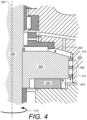
- FIG. 4 is a cross-sectional view showing further details of a thrust disk in a compressor having offloaded axial bearings, according to some embodiments.
- the thrust disk 256 is shown mounted to shaft 254 that is being driven about main longitudinal axis 300 in the direction shown by arrow 314 by an electric motor (not shown in FIG. 4 ).
- Thrust disk 256 is surrounded by a barrier fluid, which is provided at a higher pressure than the process fluid.
- the shaft 254 has a downward force imparted upon it by main impellers (e.g. impellers 352 in FIG. 3 ). The downward force is partially counteracted by the thrust disk lower bearing surface 404 engaging with thrust bearing pad 354.
- main impellers e.g. impellers 352 in FIG. 3
- the thrust disk 256 also includes multiple impellers 356 mounted on its outer surface as shown.
- the thrust disk impellers 356 are shaped and positioned to increase barrier fluid pressure along the downward direction as shown by dotted arrows 410 and 412.
- the lower surface 404 of thrust disk 256 is exposed to a higher pressure than the upper surface 402 of thrust disk 256.
- the resultant pressure differential causes an upward force on the thrust disk 256, which in combination with force imparted from impellers 356 at least partially counter acts the downward force imparted by the main impellers (e.g. impellers 352 in FIG. 3 ). In this way the thrust bearing pads 354 are at least partially offloaded.
- This offloading effect can be used to greatly reduce the maximum force that the bearing surfaces are expected to see during operation. This reduction can allow for compressor operation at higher differential pressures and/or it can be used to reduce the overall size and loss associated with the thrust disk. Note that the clearance between the tips of impellers 356 and the stationary housing 420 (i.e., the radial clearance) can be made sufficiently large to ensure mechanical robustness and integrity of the arrangement.
- FIG. 5 is a perspective view showing further details of a thrust disk having impellers mounted thereon, according to some embodiments.
- thrust disk 256 includes two rows of impellers 356.
- the impellers are shaped and positioned to increase the pressure of the surrounding barrier fluid along a downward direction, as shown by dotted arrows 502 and 504 when the thrust disk is rotated about axis 300 in the direction shown by arrow 304.
- the pressure increase causes the lower side 404 of disk 256 to be exposed to a higher fluid pressure than the upper side 402 of disk 256.
- a single row, or three or more rows of impellers can be used.
- the impellers can be positioned in other arrangements beside horizontal rows such as a staggered arrangement.
- the shape and size of the impellers can be different than the example shown.
- the radial dimension of the impellers in FIG. 5 has been exaggerated for simplicity.
- the impellers 356 may be substantially lower profile in the radial dimension than shown in FIG. 5 .
- FIG. 6 is a perspective view showing a thrust disk having alternate fluid pressure increasing structures, according to some embodiments.
- other structural mechanisms besides conventional impellers such as vanes, pump rings, labyrinths, groves etc. can be incorporated into the trust disk to increase the barrier fluid pressure in a manner that counteracts the force imparted on the shaft by the main compressor impellers.
- a number of spiral shaped grooves 656 are incorporated into the outer surface of the trust disk 256 which cause a differential pressure across the thrust disk when it is rotated.
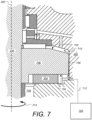
- FIG. 7 is a cross-sectional view showing further details of a thrust disk in a compressor having offloaded axial bearings, according to an example that does not form part of the claimed invention.
- a separate pumping or circulation means is used to create a differential pressure across the thrust disk 756.
- the thrust disk 756 is mounted to shaft 254 that is being driven (e.g., rotated) about main longitudinal axis 300 in the direction shown by arrow 314 by an electric motor (such as motor 252 shown in FIG. 2 ).
- Thrust disk 756 is surrounded by a barrier fluid, which is provided at a higher pressure than the process fluid.
- the shaft 254 has a downward force imparted upon it by main impellers (e.g. impellers 352 in FIG. 3 ).
- the downward force is partially counteracted by the thrust disk lower bearing surface 704 engaging with thrust bearing pad 354.
- barrier fluid pump 720 is schematically shown supplying clean barrier fluid as shown by arrow 712.
- the barrier fluid pump 720 could supply the barrier fluid to another location such as into volume 754.
- a narrow gap 758 is provided between the outer surface of thrust disk 756 and stationary housing body 420.
- the narrow gap 758 forms a flow restriction between the lower side 704 and the upper side 702 of thrust disk 756. Note that some small amount of fluid will flow upwards through gap 758 as shown by arrow 710.
- the lower surface 704 of thrust disk 756 is exposed to a higher pressure than the upper surface 702 of thrust disk 756.
- the resultant pressure differential causes an upward force on the thrust disk 756, which at least partially counter acts the downward force imparted by the main impellers (e.g. impellers 352 in FIG. 3 ).
- the thrust bearing pads 354 are at least partially offloaded. This offloading effect can be used to greatly reduce the maximum force that the bearing surfaces are expected to see during operation. This reduction can allow for compressor operation at higher differential pressures and/or it can be used to reduce the overall size and loss associated with the thrust disk.
- the barrier fluid pump 720 may be a separate circulation pump and/or impeller that is located elsewhere in the barrier circuit, such as at a different position on the shaft 254 as is common on subsea pumps and compressors.
- the pump 720 may be an external pump positioned outside the pump and/or compressor compartment.
- structures such as impellers, vanes, pump rings, labyrinths, or grooves are provided on the outside of disk 756 such as shown in FIGs. 4 , 5 and 6 in combination with barrier fluid pump 720 to further support the pressure differential across disk 756.
- a means for off-loading an axial thrust bearing is provided without the use of a process exposed balance piston.
- the disclosed techniques allow for: a smaller thrust bearing used for a given differential pressure; a larger effective differential pressure; or a combination of both. In this way an axial thrust bearing can be off-loaded without the use of a process exposed balance piston.
- the benefits of the disclosed techniques include the use of a smaller thrust bearing for a given differential pressure, and/or the ability to safely achieve larger effective differential pressures.
Landscapes
- Engineering & Computer Science (AREA)
- Mechanical Engineering (AREA)
- General Engineering & Computer Science (AREA)
- Mining & Mineral Resources (AREA)
- Structures Of Non-Positive Displacement Pumps (AREA)
Claims (15)
- Machine d'augmentation de la pression de fluide (140, 150), comprenant :une chambre de traitement de fluide (210) conçue pour contenir un fluide de traitement et comprenant une entrée (212) et une sortie (214) ;un premier élément (254) pouvant tourner autour d'un axe longitudinal central (300) ;un système de moteur (252) en prise mécaniquement sur le premier élément de manière à faire tourner l'élément autour d'un axe longitudinal dans une direction de rotation (314) ;une pluralité d'hélices (352) montées à demeure sur le premier élément et exposée au fluide de traitement à l'intérieur de la chambre de traitement de fluide de sorte que lorsque le premier élément est mis en rotation dans le la direction de rotation, les hélices agissent sur le fluide de traitement, ce qui permet d'augmenter la pression de fluide de traitement vers la sortie et une force de réaction (308) est communiquée au premier élément dans une direction axiale de la sortie vers l'entrée ; etun premier élément rotatif (256, 756) entouré d'un fluide de barrière (712) et fixé à demeure au premier élément, l'élément rotatif présentant une surface de pression supérieure (404, 704) exposée au fluide de barrière à une pression supérieure et une surface de pression inférieure (402, 702) exposée au fluide de barrière à une pression inférieure, la différence entre les pressions supérieure et inférieure agissant sur les surfaces de pression supérieure et inférieure respectives générant une force (510) sur le premier élément qui contrebalance au moins partiellement la force de réaction,dans laquelle la différence entre la pression supérieure et inférieure est au moins partiellement produite par des structures (356, 656) sur le premier élément (254) conçues pour augmenter la pression de fluide de barrière en faisant tourner le premier élément ;caractérisé en ce que le premier élément rotatif (256) est un disque de poussée (256) et les structures (356, 656) comportent une pluralité de l'un parmi les éléments suivants : roues (356), aubes, anneaux de pompe, labyrinthes et rainures (656) sur un bord extérieur du disque de poussée (256).
- Machine de traitement de fluide (140, 150) selon la revendication 1, dans laquelle la différence entre les pressions supérieure et inférieure du fluide de barrière (712) est d'au moins 10 bars ou dans laquelle la force générée sur le premier élément (254) contrebalance au moins 25 % de la force de réaction (308).
- Machine de traitement de fluide (140, 150) selon la revendication 1, dans laquelle le premier élément (254) est un élément de poussée (256, 756) présentant une surface d'appui (354) conçue pour supporter la force de réaction qui n'est pas contrecarrée par ladite force générée par la différence entre les pressions supérieure et inférieure du fluide de barrière (712).
- Machine de traitement de fluide (140, 150) selon la revendication 1, dans laquelle la machine est un compresseur sous-marin (140).
- Machine de traitement de fluide (140, 150) selon la revendication 4, dans laquelle la machine est un compresseur de gaz humide sous-marin.
- Machine de traitement de fluide (140, 150) selon la revendication 4, dans laquelle le fluide de traitement est un gaz d'hydrocarbure humide produit à partir d'une formation rocheuse souterraine.
- Machine de traitement de fluide (140, 150) selon la revendication 1, dans laquelle la machine est une pompe multiphase conçue pour être déployée dans un environnement sous-marin et le fluide de traitement contient des phases multiples.
- Machine de traitement de fluide (140, 150) selon la revendication 7, dans laquelle les phases multiples comportent de préférence des particules solides et/ou des hydrates.
- Machine de traitement de fluide (140, 150) selon la revendication 1, dans laquelle la machine est une pompe électrique submersible (150) pouvant être déployée à l'intérieur d'un puits de forage (154).
- Machine de traitement de fluide (140, 150) selon la revendication 1, dans laquelle le premier élément (254) comprend un moyeu (350) sur lequel la pluralité de roues (352) est montée en une pluralité de rangées, et la machine comprenant en outre :un second élément (244) pouvant tourner autour de l'axe longitudinal central (300), le second élément comprenant un manchon ;un second système de moteur (242) en prise mécaniquement avec le second élément de manière à faire tourner le second élément autour de l'axe longitudinal dans une seconde direction de rotation (312) qui est opposé à la direction de rotation (314) du premier élément ; etune pluralité de secondes hélices (342) étant montées à demeure sur le manchon du second élément dans une pluralité de secondes rangées de sorte que les secondes rangées s'entrelacent avec les rangées d'hélices sur le moyeu un premier élément, les seconds éléments étant exposés au fluide de traitement à l'intérieur de la chambre de traitement de fluide de sorte que lorsque le second élément est mis en rotation dans la seconde direction de rotation, les secondes hélices agissent sur le fluide de traitement, ce qui permet d'augmenter la pression de fluide de traitement vers la sortie et (214) une seconde force de réaction (306) est communiquée au second élément dans une direction axiale de la sortie vers l'entrée (212) ; etun second élément rotatif (246) entouré d'un fluide de barrière et fixé à demeure au second élément, l'élément rotatif présentant une surface de pression supérieure (404, 704) exposée au fluide de barrière à une pression supérieure et une surface de pression inférieure (402, 702) exposée au fluide de barrière à une pression inférieure, la différence entre les pressions supérieure et inférieure agissant sur les surfaces de pression supérieure et inférieure respectives générant une force sur le second élément qui contrebalance au moins partiellement la seconde force de réaction,
- Machine de traitement de fluide (140, 150) selon la revendication 1, dans laquelle la différence entre le fluide à pression supérieure et le fluide à pression inférieure est en outre partiellement produit par une pompe à fluide de barrière (720).
- Machine de traitement de fluide (140, 150) selon la revendication 1, dans laquelle le fluide de barrière (712) est moins inducteur d'usure que le fluide de traitement.
- Procédé destiné à faire fonctionner la machine d'augmentation de la pression d'un fluide selon une quelconque revendication précédente comprenant :la mise en rotation du premier élément autour de l'axe longitudinal central (300) de façon à amener la pluralité de roues (352) à entrer en prise et à augmenter la pression de fluide de traitement le long d'une première direction axiale (304), ce qui permet d'amener l'application d'une force de réaction (308) sur le premier élément dans une seconde direction axiale opposée à la première direction axiale la mise en rotation du disque de poussée présentant des structures de façon à augmenter ainsi la pression de fluide de barrièrel'amenée d'une différence de pression dans le fluide de barrière (712) dans lequel la surface de pression supérieure (404, 704) du disque de poussée exposée au fluide de barrière de pression supérieure et la surface de pression inférieure (402, 702) du disque de poussée exposée à un fluide de barrière de pression inférieure, la différence de pression dans le fluide de barrière générant une force sur le disque de poussée (256) qui contrebalance partiellement la force de réaction et décharge la surface d'appui inférieure du disque de poussée (256).
- Procédé selon la revendication 13, dans lequel le fluide de traitement est un effluent d'hydrocarbures et est produit à partir d'une formation rocheuse souterraine.
- Procédé selon la revendication 13, dans lequel le procédé est effectué dans un environnement sous-marin.
Applications Claiming Priority (2)
| Application Number | Priority Date | Filing Date | Title |
|---|---|---|---|
| US14/936,835 US20170130730A1 (en) | 2015-11-10 | 2015-11-10 | Axial bearing offloading in fluid processing machines |
| PCT/EP2016/075561 WO2017080804A1 (fr) | 2015-11-10 | 2016-10-24 | Délestage de palier axial dans des machines de traitement de fluide |
Publications (2)
| Publication Number | Publication Date |
|---|---|
| EP3374643A1 EP3374643A1 (fr) | 2018-09-19 |
| EP3374643B1 true EP3374643B1 (fr) | 2023-05-10 |
Family
ID=57184482
Family Applications (1)
| Application Number | Title | Priority Date | Filing Date |
|---|---|---|---|
| EP16784932.2A Active EP3374643B1 (fr) | 2015-11-10 | 2016-10-24 | Délestage de palier axial dans des machines de traitement de fluide |
Country Status (3)
| Country | Link |
|---|---|
| US (1) | US20170130730A1 (fr) |
| EP (1) | EP3374643B1 (fr) |
| WO (1) | WO2017080804A1 (fr) |
Families Citing this family (10)
| Publication number | Priority date | Publication date | Assignee | Title |
|---|---|---|---|---|
| CN205036629U (zh) * | 2015-09-25 | 2016-02-17 | 讯凯国际股份有限公司 | 叶轮、流体泵及液冷装置 |
| US11408432B2 (en) * | 2015-10-11 | 2022-08-09 | Schlumberger Technology Corporation | Submersible pumping system with a motor protector having a thrust runner, retention system, and passageway allowing gas flow from a lower region into an upper region |
| EP3171028B1 (fr) * | 2015-11-19 | 2019-08-14 | Grundfos Holding A/S | Pompe centrifuge multicellulaire avec un piston d'équilibrage de poussée axiale dont les faces de haute et basse pression sont séparées par une garniture mécanique |
| US11168551B2 (en) | 2016-10-23 | 2021-11-09 | Schlumberger Technology Corporation | Gas purging for electric submersible pumping system |
| US10513928B2 (en) * | 2017-08-31 | 2019-12-24 | Flowserve Management Company | Axial thrust balancing device |
| US11231039B2 (en) | 2018-08-31 | 2022-01-25 | Onesubsea Ip Uk Limited | Thrust-balancing wet gas compressor |
| US10844701B2 (en) * | 2019-02-05 | 2020-11-24 | Saudi Arabian Oil Company | Balancing axial thrust in submersible well pumps |
| US11808278B2 (en) * | 2019-05-13 | 2023-11-07 | Onesubsea Ip Uk Limited | Bearing system for vertical shafts |
| DE102019219080A1 (de) * | 2019-12-06 | 2021-06-10 | Robert Bosch Gmbh | Verdichter |
| US11629720B2 (en) * | 2020-09-29 | 2023-04-18 | Extract Management Company, Llc | Thrust box and skid for a horizontally mounted submersible pump |
Citations (4)
| Publication number | Priority date | Publication date | Assignee | Title |
|---|---|---|---|---|
| US5256038A (en) * | 1991-11-12 | 1993-10-26 | Sundstrand Corp. | Canned motor pump |
| DE102012211796A1 (de) * | 2012-07-06 | 2014-01-23 | Robert Bosch Gmbh | Axiallager |
| WO2015011366A2 (fr) * | 2013-07-22 | 2015-01-29 | Snecma | Pompe centrifuge, en particulier pour l'alimentation de moteurs de fusee |
| WO2015032510A1 (fr) * | 2013-09-03 | 2015-03-12 | Nuovo Pignone Srl | Machine électrique refroidie par ventilateur à compensation de poussée axiale |
Family Cites Families (3)
| Publication number | Priority date | Publication date | Assignee | Title |
|---|---|---|---|---|
| NL176296B (nl) * | 1974-01-30 | 1984-10-16 | Gutehoffnungshuette Sterkrade | Roterende hogedruk-compressor. |
| US7416525B2 (en) * | 2003-09-18 | 2008-08-26 | Myrakelle, Llc | Rotary blood pump |
| JP6049385B2 (ja) * | 2012-10-04 | 2016-12-21 | 株式会社日立製作所 | 遠心圧縮機 |
-
2015
- 2015-11-10 US US14/936,835 patent/US20170130730A1/en not_active Abandoned
-
2016
- 2016-10-24 WO PCT/EP2016/075561 patent/WO2017080804A1/fr not_active Ceased
- 2016-10-24 EP EP16784932.2A patent/EP3374643B1/fr active Active
Patent Citations (4)
| Publication number | Priority date | Publication date | Assignee | Title |
|---|---|---|---|---|
| US5256038A (en) * | 1991-11-12 | 1993-10-26 | Sundstrand Corp. | Canned motor pump |
| DE102012211796A1 (de) * | 2012-07-06 | 2014-01-23 | Robert Bosch Gmbh | Axiallager |
| WO2015011366A2 (fr) * | 2013-07-22 | 2015-01-29 | Snecma | Pompe centrifuge, en particulier pour l'alimentation de moteurs de fusee |
| WO2015032510A1 (fr) * | 2013-09-03 | 2015-03-12 | Nuovo Pignone Srl | Machine électrique refroidie par ventilateur à compensation de poussée axiale |
Also Published As
| Publication number | Publication date |
|---|---|
| US20170130730A1 (en) | 2017-05-11 |
| EP3374643A1 (fr) | 2018-09-19 |
| WO2017080804A1 (fr) | 2017-05-18 |
Similar Documents
| Publication | Publication Date | Title |
|---|---|---|
| US20170130730A1 (en) | Axial bearing offloading in fluid processing machines | |
| EP3527830B1 (fr) | Système de déplacement de fluides à l'aide de forces axiales opposées | |
| EP3913227B1 (fr) | Pompe à phases multiples | |
| EP3332125B1 (fr) | Machines de traitement de fluide et systèmes de production de fluide | |
| EP2598753B1 (fr) | Pompe ou moteur de type à vis | |
| US10907643B2 (en) | Press-fit thrust bearing system and apparatus | |
| US20150226219A1 (en) | Self-Aligning and Vibration Damping Bearings in a Submersible Well Pump | |
| WO2005081766A2 (fr) | Turbine radiale conique sans aubes et procede associe | |
| AU2015363802B2 (en) | Centrifugal pressure booster and method for modifying or constructing a centrifugal pressure booster | |
| US20190186245A1 (en) | Lubricant Circulating Pump For Electrical Submersible Pump Motor | |
| EP3812596A1 (fr) | Pompe multiphase avec amortisseur de palier à film de fluide comprimé | |
| US9303648B2 (en) | Compliant radial bearing for electrical submersible pump | |
| WO2012141879A2 (fr) | Mobile comportant une pompe à rotor intégré | |
| US20170241424A1 (en) | Apertures Spaced Around Impeller Bottom Shroud of Centrifugal Pump | |
| US20160258441A1 (en) | Abrasion-resistant thrust ring for use with a downhole electrical submersible pump | |
| EP3584405B1 (fr) | Système de mouvement de fluide dos à dos contrarotatif | |
| US20200340481A1 (en) | Permanent magnet pump with bearings separating modular sections | |
| US20230191289A1 (en) | Particulate restriction for fluid pumps | |
| US11808278B2 (en) | Bearing system for vertical shafts | |
| RU2250392C2 (ru) | Погружной многоступенчатый центробежный насос с радиально-опорными подшипниками | |
| AU2016269666A1 (en) | Combined bearing and turbomachine including said bearing | |
| US20250101994A1 (en) | System and method for vibration control |
Legal Events
| Date | Code | Title | Description |
|---|---|---|---|
| STAA | Information on the status of an ep patent application or granted ep patent |
Free format text: STATUS: UNKNOWN |
|
| STAA | Information on the status of an ep patent application or granted ep patent |
Free format text: STATUS: THE INTERNATIONAL PUBLICATION HAS BEEN MADE |
|
| PUAI | Public reference made under article 153(3) epc to a published international application that has entered the european phase |
Free format text: ORIGINAL CODE: 0009012 |
|
| STAA | Information on the status of an ep patent application or granted ep patent |
Free format text: STATUS: REQUEST FOR EXAMINATION WAS MADE |
|
| 17P | Request for examination filed |
Effective date: 20180606 |
|
| AK | Designated contracting states |
Kind code of ref document: A1 Designated state(s): AL AT BE BG CH CY CZ DE DK EE ES FI FR GB GR HR HU IE IS IT LI LT LU LV MC MK MT NL NO PL PT RO RS SE SI SK SM TR |
|
| AX | Request for extension of the european patent |
Extension state: BA ME |
|
| DAV | Request for validation of the european patent (deleted) | ||
| DAX | Request for extension of the european patent (deleted) | ||
| STAA | Information on the status of an ep patent application or granted ep patent |
Free format text: STATUS: EXAMINATION IS IN PROGRESS |
|
| 17Q | First examination report despatched |
Effective date: 20200625 |
|
| GRAP | Despatch of communication of intention to grant a patent |
Free format text: ORIGINAL CODE: EPIDOSNIGR1 |
|
| STAA | Information on the status of an ep patent application or granted ep patent |
Free format text: STATUS: GRANT OF PATENT IS INTENDED |
|
| INTG | Intention to grant announced |
Effective date: 20220624 |
|
| GRAJ | Information related to disapproval of communication of intention to grant by the applicant or resumption of examination proceedings by the epo deleted |
Free format text: ORIGINAL CODE: EPIDOSDIGR1 |
|
| STAA | Information on the status of an ep patent application or granted ep patent |
Free format text: STATUS: EXAMINATION IS IN PROGRESS |
|
| GRAP | Despatch of communication of intention to grant a patent |
Free format text: ORIGINAL CODE: EPIDOSNIGR1 |
|
| STAA | Information on the status of an ep patent application or granted ep patent |
Free format text: STATUS: GRANT OF PATENT IS INTENDED |
|
| INTC | Intention to grant announced (deleted) | ||
| INTG | Intention to grant announced |
Effective date: 20221124 |
|
| GRAS | Grant fee paid |
Free format text: ORIGINAL CODE: EPIDOSNIGR3 |
|
| GRAA | (expected) grant |
Free format text: ORIGINAL CODE: 0009210 |
|
| STAA | Information on the status of an ep patent application or granted ep patent |
Free format text: STATUS: THE PATENT HAS BEEN GRANTED |
|
| AK | Designated contracting states |
Kind code of ref document: B1 Designated state(s): AL AT BE BG CH CY CZ DE DK EE ES FI FR GB GR HR HU IE IS IT LI LT LU LV MC MK MT NL NO PL PT RO RS SE SI SK SM TR |
|
| REG | Reference to a national code |
Ref country code: GB Ref legal event code: FG4D |
|
| REG | Reference to a national code |
Ref country code: AT Ref legal event code: REF Ref document number: 1566920 Country of ref document: AT Kind code of ref document: T Effective date: 20230515 Ref country code: CH Ref legal event code: EP |
|
| REG | Reference to a national code |
Ref country code: DE Ref legal event code: R096 Ref document number: 602016079359 Country of ref document: DE |
|
| REG | Reference to a national code |
Ref country code: IE Ref legal event code: FG4D |
|
| REG | Reference to a national code |
Ref country code: LT Ref legal event code: MG9D |
|
| REG | Reference to a national code |
Ref country code: NL Ref legal event code: MP Effective date: 20230510 |
|
| REG | Reference to a national code |
Ref country code: AT Ref legal event code: MK05 Ref document number: 1566920 Country of ref document: AT Kind code of ref document: T Effective date: 20230510 |
|
| PG25 | Lapsed in a contracting state [announced via postgrant information from national office to epo] |
Ref country code: SE Free format text: LAPSE BECAUSE OF FAILURE TO SUBMIT A TRANSLATION OF THE DESCRIPTION OR TO PAY THE FEE WITHIN THE PRESCRIBED TIME-LIMIT Effective date: 20230510 Ref country code: PT Free format text: LAPSE BECAUSE OF FAILURE TO SUBMIT A TRANSLATION OF THE DESCRIPTION OR TO PAY THE FEE WITHIN THE PRESCRIBED TIME-LIMIT Effective date: 20230911 Ref country code: NO Free format text: LAPSE BECAUSE OF FAILURE TO SUBMIT A TRANSLATION OF THE DESCRIPTION OR TO PAY THE FEE WITHIN THE PRESCRIBED TIME-LIMIT Effective date: 20230810 Ref country code: NL Free format text: LAPSE BECAUSE OF FAILURE TO SUBMIT A TRANSLATION OF THE DESCRIPTION OR TO PAY THE FEE WITHIN THE PRESCRIBED TIME-LIMIT Effective date: 20230510 Ref country code: ES Free format text: LAPSE BECAUSE OF FAILURE TO SUBMIT A TRANSLATION OF THE DESCRIPTION OR TO PAY THE FEE WITHIN THE PRESCRIBED TIME-LIMIT Effective date: 20230510 Ref country code: AT Free format text: LAPSE BECAUSE OF FAILURE TO SUBMIT A TRANSLATION OF THE DESCRIPTION OR TO PAY THE FEE WITHIN THE PRESCRIBED TIME-LIMIT Effective date: 20230510 |
|
| PG25 | Lapsed in a contracting state [announced via postgrant information from national office to epo] |
Ref country code: RS Free format text: LAPSE BECAUSE OF FAILURE TO SUBMIT A TRANSLATION OF THE DESCRIPTION OR TO PAY THE FEE WITHIN THE PRESCRIBED TIME-LIMIT Effective date: 20230510 Ref country code: PL Free format text: LAPSE BECAUSE OF FAILURE TO SUBMIT A TRANSLATION OF THE DESCRIPTION OR TO PAY THE FEE WITHIN THE PRESCRIBED TIME-LIMIT Effective date: 20230510 Ref country code: LV Free format text: LAPSE BECAUSE OF FAILURE TO SUBMIT A TRANSLATION OF THE DESCRIPTION OR TO PAY THE FEE WITHIN THE PRESCRIBED TIME-LIMIT Effective date: 20230510 Ref country code: LT Free format text: LAPSE BECAUSE OF FAILURE TO SUBMIT A TRANSLATION OF THE DESCRIPTION OR TO PAY THE FEE WITHIN THE PRESCRIBED TIME-LIMIT Effective date: 20230510 Ref country code: IS Free format text: LAPSE BECAUSE OF FAILURE TO SUBMIT A TRANSLATION OF THE DESCRIPTION OR TO PAY THE FEE WITHIN THE PRESCRIBED TIME-LIMIT Effective date: 20230910 Ref country code: HR Free format text: LAPSE BECAUSE OF FAILURE TO SUBMIT A TRANSLATION OF THE DESCRIPTION OR TO PAY THE FEE WITHIN THE PRESCRIBED TIME-LIMIT Effective date: 20230510 Ref country code: GR Free format text: LAPSE BECAUSE OF FAILURE TO SUBMIT A TRANSLATION OF THE DESCRIPTION OR TO PAY THE FEE WITHIN THE PRESCRIBED TIME-LIMIT Effective date: 20230811 |
|
| PG25 | Lapsed in a contracting state [announced via postgrant information from national office to epo] |
Ref country code: FI Free format text: LAPSE BECAUSE OF FAILURE TO SUBMIT A TRANSLATION OF THE DESCRIPTION OR TO PAY THE FEE WITHIN THE PRESCRIBED TIME-LIMIT Effective date: 20230510 |
|
| PG25 | Lapsed in a contracting state [announced via postgrant information from national office to epo] |
Ref country code: SK Free format text: LAPSE BECAUSE OF FAILURE TO SUBMIT A TRANSLATION OF THE DESCRIPTION OR TO PAY THE FEE WITHIN THE PRESCRIBED TIME-LIMIT Effective date: 20230510 |
|
| P01 | Opt-out of the competence of the unified patent court (upc) registered |
Effective date: 20231212 |
|
| PG25 | Lapsed in a contracting state [announced via postgrant information from national office to epo] |
Ref country code: SM Free format text: LAPSE BECAUSE OF FAILURE TO SUBMIT A TRANSLATION OF THE DESCRIPTION OR TO PAY THE FEE WITHIN THE PRESCRIBED TIME-LIMIT Effective date: 20230510 Ref country code: SK Free format text: LAPSE BECAUSE OF FAILURE TO SUBMIT A TRANSLATION OF THE DESCRIPTION OR TO PAY THE FEE WITHIN THE PRESCRIBED TIME-LIMIT Effective date: 20230510 Ref country code: RO Free format text: LAPSE BECAUSE OF FAILURE TO SUBMIT A TRANSLATION OF THE DESCRIPTION OR TO PAY THE FEE WITHIN THE PRESCRIBED TIME-LIMIT Effective date: 20230510 Ref country code: EE Free format text: LAPSE BECAUSE OF FAILURE TO SUBMIT A TRANSLATION OF THE DESCRIPTION OR TO PAY THE FEE WITHIN THE PRESCRIBED TIME-LIMIT Effective date: 20230510 Ref country code: DK Free format text: LAPSE BECAUSE OF FAILURE TO SUBMIT A TRANSLATION OF THE DESCRIPTION OR TO PAY THE FEE WITHIN THE PRESCRIBED TIME-LIMIT Effective date: 20230510 Ref country code: CZ Free format text: LAPSE BECAUSE OF FAILURE TO SUBMIT A TRANSLATION OF THE DESCRIPTION OR TO PAY THE FEE WITHIN THE PRESCRIBED TIME-LIMIT Effective date: 20230510 |
|
| REG | Reference to a national code |
Ref country code: DE Ref legal event code: R097 Ref document number: 602016079359 Country of ref document: DE |
|
| PLBE | No opposition filed within time limit |
Free format text: ORIGINAL CODE: 0009261 |
|
| STAA | Information on the status of an ep patent application or granted ep patent |
Free format text: STATUS: NO OPPOSITION FILED WITHIN TIME LIMIT |
|
| 26N | No opposition filed |
Effective date: 20240213 |
|
| REG | Reference to a national code |
Ref country code: DE Ref legal event code: R119 Ref document number: 602016079359 Country of ref document: DE |
|
| PG25 | Lapsed in a contracting state [announced via postgrant information from national office to epo] |
Ref country code: SI Free format text: LAPSE BECAUSE OF FAILURE TO SUBMIT A TRANSLATION OF THE DESCRIPTION OR TO PAY THE FEE WITHIN THE PRESCRIBED TIME-LIMIT Effective date: 20230510 |
|
| PG25 | Lapsed in a contracting state [announced via postgrant information from national office to epo] |
Ref country code: SI Free format text: LAPSE BECAUSE OF FAILURE TO SUBMIT A TRANSLATION OF THE DESCRIPTION OR TO PAY THE FEE WITHIN THE PRESCRIBED TIME-LIMIT Effective date: 20230510 Ref country code: IT Free format text: LAPSE BECAUSE OF FAILURE TO SUBMIT A TRANSLATION OF THE DESCRIPTION OR TO PAY THE FEE WITHIN THE PRESCRIBED TIME-LIMIT Effective date: 20230510 Ref country code: MC Free format text: LAPSE BECAUSE OF FAILURE TO SUBMIT A TRANSLATION OF THE DESCRIPTION OR TO PAY THE FEE WITHIN THE PRESCRIBED TIME-LIMIT Effective date: 20230510 |
|
| REG | Reference to a national code |
Ref country code: CH Ref legal event code: PL |
|
| REG | Reference to a national code |
Ref country code: BE Ref legal event code: MM Effective date: 20231031 |
|
| PG25 | Lapsed in a contracting state [announced via postgrant information from national office to epo] |
Ref country code: LU Free format text: LAPSE BECAUSE OF NON-PAYMENT OF DUE FEES Effective date: 20231024 |
|
| GBPC | Gb: european patent ceased through non-payment of renewal fee |
Effective date: 20231024 |
|
| PG25 | Lapsed in a contracting state [announced via postgrant information from national office to epo] |
Ref country code: LU Free format text: LAPSE BECAUSE OF NON-PAYMENT OF DUE FEES Effective date: 20231024 |
|
| PG25 | Lapsed in a contracting state [announced via postgrant information from national office to epo] |
Ref country code: GB Free format text: LAPSE BECAUSE OF NON-PAYMENT OF DUE FEES Effective date: 20231024 |
|
| PG25 | Lapsed in a contracting state [announced via postgrant information from national office to epo] |
Ref country code: CH Free format text: LAPSE BECAUSE OF NON-PAYMENT OF DUE FEES Effective date: 20231031 |
|
| PG25 | Lapsed in a contracting state [announced via postgrant information from national office to epo] |
Ref country code: GB Free format text: LAPSE BECAUSE OF NON-PAYMENT OF DUE FEES Effective date: 20231024 Ref country code: FR Free format text: LAPSE BECAUSE OF NON-PAYMENT OF DUE FEES Effective date: 20231031 Ref country code: DE Free format text: LAPSE BECAUSE OF NON-PAYMENT OF DUE FEES Effective date: 20240501 Ref country code: CH Free format text: LAPSE BECAUSE OF NON-PAYMENT OF DUE FEES Effective date: 20231031 |
|
| PG25 | Lapsed in a contracting state [announced via postgrant information from national office to epo] |
Ref country code: BE Free format text: LAPSE BECAUSE OF NON-PAYMENT OF DUE FEES Effective date: 20231031 |
|
| PG25 | Lapsed in a contracting state [announced via postgrant information from national office to epo] |
Ref country code: IE Free format text: LAPSE BECAUSE OF NON-PAYMENT OF DUE FEES Effective date: 20231024 |
|
| PG25 | Lapsed in a contracting state [announced via postgrant information from national office to epo] |
Ref country code: IE Free format text: LAPSE BECAUSE OF NON-PAYMENT OF DUE FEES Effective date: 20231024 |
|
| PG25 | Lapsed in a contracting state [announced via postgrant information from national office to epo] |
Ref country code: BG Free format text: LAPSE BECAUSE OF FAILURE TO SUBMIT A TRANSLATION OF THE DESCRIPTION OR TO PAY THE FEE WITHIN THE PRESCRIBED TIME-LIMIT Effective date: 20230510 |
|
| PG25 | Lapsed in a contracting state [announced via postgrant information from national office to epo] |
Ref country code: BG Free format text: LAPSE BECAUSE OF FAILURE TO SUBMIT A TRANSLATION OF THE DESCRIPTION OR TO PAY THE FEE WITHIN THE PRESCRIBED TIME-LIMIT Effective date: 20230510 |
|
| PG25 | Lapsed in a contracting state [announced via postgrant information from national office to epo] |
Ref country code: CY Free format text: LAPSE BECAUSE OF FAILURE TO SUBMIT A TRANSLATION OF THE DESCRIPTION OR TO PAY THE FEE WITHIN THE PRESCRIBED TIME-LIMIT; INVALID AB INITIO Effective date: 20161024 |
|
| PG25 | Lapsed in a contracting state [announced via postgrant information from national office to epo] |
Ref country code: HU Free format text: LAPSE BECAUSE OF FAILURE TO SUBMIT A TRANSLATION OF THE DESCRIPTION OR TO PAY THE FEE WITHIN THE PRESCRIBED TIME-LIMIT; INVALID AB INITIO Effective date: 20161024 |
|
| PG25 | Lapsed in a contracting state [announced via postgrant information from national office to epo] |
Ref country code: TR Free format text: LAPSE BECAUSE OF FAILURE TO SUBMIT A TRANSLATION OF THE DESCRIPTION OR TO PAY THE FEE WITHIN THE PRESCRIBED TIME-LIMIT Effective date: 20230510 |