EP3374657B1 - Bremsbelag mit einem bremsbelagtaktungs- und -rückzugsteuergerät mit sperrverbindung - Google Patents
Bremsbelag mit einem bremsbelagtaktungs- und -rückzugsteuergerät mit sperrverbindung Download PDFInfo
- Publication number
- EP3374657B1 EP3374657B1 EP16798367.5A EP16798367A EP3374657B1 EP 3374657 B1 EP3374657 B1 EP 3374657B1 EP 16798367 A EP16798367 A EP 16798367A EP 3374657 B1 EP3374657 B1 EP 3374657B1
- Authority
- EP
- European Patent Office
- Prior art keywords
- shaft
- brake pad
- brake
- bore
- backing plate
- Prior art date
- Legal status (The legal status is an assumption and is not a legal conclusion. Google has not performed a legal analysis and makes no representation as to the accuracy of the status listed.)
- Active
Links
Images



Classifications
-
- F—MECHANICAL ENGINEERING; LIGHTING; HEATING; WEAPONS; BLASTING
- F16—ENGINEERING ELEMENTS AND UNITS; GENERAL MEASURES FOR PRODUCING AND MAINTAINING EFFECTIVE FUNCTIONING OF MACHINES OR INSTALLATIONS; THERMAL INSULATION IN GENERAL
- F16D—COUPLINGS FOR TRANSMITTING ROTATION; CLUTCHES; BRAKES
- F16D65/00—Parts or details
- F16D65/38—Slack adjusters
- F16D65/40—Slack adjusters mechanical
- F16D65/52—Slack adjusters mechanical self-acting in one direction for adjusting excessive play
- F16D65/56—Slack adjusters mechanical self-acting in one direction for adjusting excessive play with screw-thread and nut
- F16D65/567—Slack adjusters mechanical self-acting in one direction for adjusting excessive play with screw-thread and nut for mounting on a disc brake
-
- F—MECHANICAL ENGINEERING; LIGHTING; HEATING; WEAPONS; BLASTING
- F16—ENGINEERING ELEMENTS AND UNITS; GENERAL MEASURES FOR PRODUCING AND MAINTAINING EFFECTIVE FUNCTIONING OF MACHINES OR INSTALLATIONS; THERMAL INSULATION IN GENERAL
- F16D—COUPLINGS FOR TRANSMITTING ROTATION; CLUTCHES; BRAKES
- F16D65/00—Parts or details
- F16D65/02—Braking members; Mounting thereof
- F16D65/04—Bands, shoes or pads; Pivots or supporting members therefor
- F16D65/092—Bands, shoes or pads; Pivots or supporting members therefor for axially-engaging brakes, e.g. disc brakes
- F16D65/095—Pivots or supporting members therefor
-
- F—MECHANICAL ENGINEERING; LIGHTING; HEATING; WEAPONS; BLASTING
- F16—ENGINEERING ELEMENTS AND UNITS; GENERAL MEASURES FOR PRODUCING AND MAINTAINING EFFECTIVE FUNCTIONING OF MACHINES OR INSTALLATIONS; THERMAL INSULATION IN GENERAL
- F16D—COUPLINGS FOR TRANSMITTING ROTATION; CLUTCHES; BRAKES
- F16D65/00—Parts or details
- F16D65/0006—Noise or vibration control
-
- F—MECHANICAL ENGINEERING; LIGHTING; HEATING; WEAPONS; BLASTING
- F16—ENGINEERING ELEMENTS AND UNITS; GENERAL MEASURES FOR PRODUCING AND MAINTAINING EFFECTIVE FUNCTIONING OF MACHINES OR INSTALLATIONS; THERMAL INSULATION IN GENERAL
- F16D—COUPLINGS FOR TRANSMITTING ROTATION; CLUTCHES; BRAKES
- F16D65/00—Parts or details
- F16D65/38—Slack adjusters
- F16D65/40—Slack adjusters mechanical
- F16D65/52—Slack adjusters mechanical self-acting in one direction for adjusting excessive play
- F16D65/54—Slack adjusters mechanical self-acting in one direction for adjusting excessive play by means of direct linear adjustment
-
- F—MECHANICAL ENGINEERING; LIGHTING; HEATING; WEAPONS; BLASTING
- F16—ENGINEERING ELEMENTS AND UNITS; GENERAL MEASURES FOR PRODUCING AND MAINTAINING EFFECTIVE FUNCTIONING OF MACHINES OR INSTALLATIONS; THERMAL INSULATION IN GENERAL
- F16D—COUPLINGS FOR TRANSMITTING ROTATION; CLUTCHES; BRAKES
- F16D55/00—Brakes with substantially-radial braking surfaces pressed together in axial direction, e.g. disc brakes
- F16D2055/0004—Parts or details of disc brakes
- F16D2055/0016—Brake calipers
- F16D2055/0029—Retraction devices
-
- F—MECHANICAL ENGINEERING; LIGHTING; HEATING; WEAPONS; BLASTING
- F16—ENGINEERING ELEMENTS AND UNITS; GENERAL MEASURES FOR PRODUCING AND MAINTAINING EFFECTIVE FUNCTIONING OF MACHINES OR INSTALLATIONS; THERMAL INSULATION IN GENERAL
- F16D—COUPLINGS FOR TRANSMITTING ROTATION; CLUTCHES; BRAKES
- F16D65/00—Parts or details
- F16D65/02—Braking members; Mounting thereof
- F16D2065/13—Parts or details of discs or drums
- F16D2065/134—Connection
- F16D2065/1392—Connection elements
- F16D2065/1396—Ancillary resilient elements, e.g. anti-rattle or retraction springs
-
- F—MECHANICAL ENGINEERING; LIGHTING; HEATING; WEAPONS; BLASTING
- F16—ENGINEERING ELEMENTS AND UNITS; GENERAL MEASURES FOR PRODUCING AND MAINTAINING EFFECTIVE FUNCTIONING OF MACHINES OR INSTALLATIONS; THERMAL INSULATION IN GENERAL
- F16D—COUPLINGS FOR TRANSMITTING ROTATION; CLUTCHES; BRAKES
- F16D2127/00—Auxiliary mechanisms
- F16D2127/02—Release mechanisms
-
- F—MECHANICAL ENGINEERING; LIGHTING; HEATING; WEAPONS; BLASTING
- F16—ENGINEERING ELEMENTS AND UNITS; GENERAL MEASURES FOR PRODUCING AND MAINTAINING EFFECTIVE FUNCTIONING OF MACHINES OR INSTALLATIONS; THERMAL INSULATION IN GENERAL
- F16D—COUPLINGS FOR TRANSMITTING ROTATION; CLUTCHES; BRAKES
- F16D2127/00—Auxiliary mechanisms
- F16D2127/06—Locking mechanisms, e.g. acting on actuators, on release mechanisms or on force transmission mechanisms
Definitions
- the teachings herein generally relate to a brake pad useable with a brake pad retraction system and a brake assembly.
- Brake calipers for automotive disc brakes are well known in the prior art.
- a rotor is mounted on a wheel hub for rotation.
- One or more pairs of brake pads are supported on either side of the rotor by a caliper or an anchor bracket.
- Calipers are designed to apply the braking force by moving a piston relative to the rotor to move the brake pad into and out of contact with the rotor.
- the pistons are supported in a bore in the caliper and abut the backing plate of the brake pad to move the brake pad toward the rotor upon application of a braking pressure.
- the pistons are connected to elastomeric seal sleeves which normally withdraw the pistons, and hence the brake pad, into a non-engaging position with respect to the rotor.
- actuation force is generated hydraulically or mechanically.
- pressure is generated in the master cylinder or by a pump of the brake system, which conducts pressurized hydraulic fluid to the pistons in the caliper.
- the pressure of the hydraulic fluid against the ends of the pistons overcomes the withdrawing force that the elastomeric seal sleeves apply to the pistons, causing them to extend and to engage the brake pad against the rotor, thereby applying a braking force to the wheels of the vehicle.
- the brake caliper of the invention comprises a caliper housing, a brake pad having a braking surface that selectively engages a brake rotor, at least one reacting member such a hydraulic piston mounted in the housing that extends and retracts the brake pad into and out of frictional engagement with said rotor; and a brake pad timing and retraction controller including at least one resilient member with limited compression travel.
- the brake pad timing and retraction controller biases against extension by applying an adjustable hold-off force against an extension force applied to said brake pad by the reacting member that momentarily delays extension and slightly reduces the resulting clamping force between the brake pad and the rotor.
- the controller also forces positive and uniform retraction of the brake pad from the rotor, thereby minimizing parasitic braking. Additionally, the controller positively retracts the brake pad from the rotor a consistent distance throughout the wear life of the brake pad and rotor, rendering the mechanism self-adjusting.
- the controller also damps out-of-plane vibration between the brake pad and rotor.
- the use of separate controllers on opposing brake pads in an opposing brake caliper results in the application of independent pull back forces on the pads, thereby insuring that both pads will be positively and uniformly retracted out of engagement with the rotor.
- the brake pad timing and retraction controller includes a bolt having a shaft that includes an end prepared for attachment to the brake pad which may be a threaded end. The threaded end is connected to the brake pad, and the shaft is movably mounted with respect to the housing.
- the controller also includes a caliper retraction collar frictionally engaged but slidably movable on the bolt shaft arid spaced apart from the threaded end, and the caliper housing includes first and second telescoping bores slightly larger than the bolt shaft and the collar, respectively, for slidably receiving the threaded end and the piston retraction collar. The resilient member is captured between the caliper retraction collar and the annular interface between the first and second counter bores.
- the stroke length of the resilient member is adjustable and may be between about 2.0 mm and 0.025 mm, and is preferably between about 0.30 mm and 0.050 mm.
- the resilient member is preferably formed from a Belleville spring, although a disc spring, certain types of leaf springs or a sheet of elastomeric material may also be used.
- the resilient member may include a plurality of Belleville springs. While the stroke length may be adjusted by selecting a stack of Belleville springs with the proper spring properties, it is preferable to adjust the stroke length by varying the profile of the spring-engaging side of the collar. As either end of the collar may be used to engage the spring, and as the cylindrical shape of the collar renders it reversible, the collar has two potentially spring-engaging surfaces.
- One of these surfaces may be provided with aflat profile to maximize the stroke length of the resilient member, while the other of these surfaces may have (in the case where the resilient element is a Belleville spring) a chamfered, dish-shaped profile that is partially complementary in shape to the resilient element in order to shorten the stroke length of the resilient member.
- the resilient element is a Belleville spring
- Such a structure advantageously allows the stroke length of the resilient member used in the brake pad timing and retraction controller to be easily varied by reversing the orientation of the collar on the bolt shaft.
- stroke length may also be controlled by machining a shape into the annular interface that captures the spring which is complementary at least in part to the shape of the spring, or by providing a spacer between the annular interface and the spring.
- the brake caliper of the invention may be used in combination with a brake of an automotive vehicle.
- the spring force of the resilient member is preferably selected to create a momentary delay and a hold-off force against the extension force of the reacting member that results in a slight relative reduction in brake clamping force between the operation of, for example, the rear brakes and the front brakes. Accordingly, the invention may be used to provide front brake bias during the entire braking operation, thereby maximizing control of the vehicle during the braking operation.
- Such a desired momentary delay and slight reduction in clamping force of the rear brakes verses the front brakes may be accomplished by applying the caliper of the invention to the rear brakes only, but is more preferably accomplished by applying the caliper of the invention to the brakes of both the front and rear wheels, with the spring properties (i.e. travel distance or spring force) of the resilient member being different between the rear brake calipers and the front brake calipers in response to the actuation forces applied by the reacting members.
- left wheel-right wheel brake timing biases may also be implemented by the invention, which may be useful in certain race car driving applications.
- the restorative force of the resilient member used in the brake pad timing and retraction controller not only advantageously adjusts brake timing, but also substantially increases the effective miles obtained per gallon of fuel and reduces brake wear due to a substantial decrease in parasitic braking. It is observed that the resiliency provided by the resilient member used in the brake pad timing and retraction controller also damps out-of-plane vibration between the brake pad and rotor, thereby reducing brake squeal.
- the brake pad timing and reaction controller with a connection lock between a shaft of the controller and the brake pad to provide a locking force that is sufficient and counteractive against the effects of vibration, heat and torques typically imposed upon the connection during a braking action, especially those effects tending to rotate components of the connection out of a full and secure engagement.
- US 2011/094834 1 discloses a brake caliper is provided with a timing and retraction controller that that adjusts brake timing, eliminates parasitic brake losses and dampens out-of-plane vibration between the brake pad and rotor.
- the brake caliper includes a housing disposed over a brake rotor; first and second opposing brake pads extendably and retractably mounted on opposite sides of the caliper housing, brake pistons that extend and retract the brake pads into and out of frictional engagement with the rotor, and brake pad timing and retraction controllers disposed on opposite sides of the caliper housing.
- Automatically adjusting brakes, and in particular self-adjusting brakes of the disc type are disclosed in US 2 536 269 A .
- US 2011/266099 discloses a brake retractor assembly for a vehicle, such as an agricultural vehicle, includes a brake housing and a brake cover defining a friction chamber.
- a brake piston is arranged within the friction chamber and coupled to the brake cover by a bolt including a first end coupled to the brake cover and a second end coupled to the brake piston. A portion of the second end passes through the brake piston via a bore defined in the brake piston and is fixedly retained to the brake piston.
- US 2004/195056 A1 discloses a disc brake assembly comprising an anchor bracket, a brake shoe which carries a friction lining, the shoe being slidably supported by the anchor bracket. The assembly includes a retraction mechanism which is adapted to retract the shoe from the disc when the brake is released.
- a brake shoe is disclosed in GB 2 399 607 A , the brake shoe having on its first side a friction pad, and at least one pin on its second side, said pin having a cross section wherein a first dimension along first direction is larger than a second dimension along a second transverse direction, there being received on each pin a spring clip to enable the shoe to be mounted.
- the locking connection comprises a bore in the backing plate, the bore being adapted to receive a flanged binding post having a threaded bore.
- the threaded bore is adapted to threadingly receive the end portion of a controller shaft whereby a flange portion of the flanged binding post is brought into contact with a backside of the backing plate.
- the engaging component comprises the threaded bore of flanged binding post and the locking component comprising a tightening of the flanged portion against the backside of the backing plate.
- the engaging portion comprises a fit between a bore provide in the backing plate and the shaft end portion, and the locking component comprises a lock screw.
- the aforementioned fit may comprise at least one of a friction fit, and a threaded fit.
- the engaging portion comprises a fit between a bore provide in the backing plate and the shaft end portion and the locking component comprises a retaining ring.
- the retaining ring may be retained in an annular recess provided in the bore in the backing plate or retained in an annular recess provided on the shaft end portion.
- the engaging portion comprises a fit between a bore provide in the backing plate and the shaft end portion and the locking component comprises a slot and a key operative along at least a portion of the bore, the key being movable into a transverse direction into a locking relationship between the shaft end portion and the backing plate.
- the slot may be provided along the bore in the backing plate or the key may be provided at a location along the bore in the backing plate.
- the engaging portion comprises a fit between a bore provided in the backing plate and the shaft end portion
- the locking component comprises a release pin operative at a location along the bore
- the engaging component comprises an initial friction fit between a bore provided in the backing plate and the shaft end portion, whereby a desired alignment of the controller shaft is achieved, and the locking component comprises a press fit established with the aligned controller shaft.
- the engaging component may further comprises contact between a rim of the bore in the backing plate and a shoulder at a trailing location along the shaft end portion.
- the engaging portion comprises a fit between a bore provide in the backing plate and the shaft end portion
- the locking component comprises a locking wire.
- the aforementioned fit is threaded fit.
- the controller shaft may include a transverse channel adjacent the shaft end portion and the backing plate may include a second bore adjacent the bore, with the locking wire being extended through the channel and the second bore.
- the locking wire may include a wound portion which establishes a tension in the locking wire.
- the locking wire may be disposed about the shaft at the transverse channel so that the tension in the wire is in a direction of a tightening of the threaded fit.
- the teachings herein also provide a non-claimed novel brake caliper comprising a brake pad, a housing having a rim portion and a brake pad timing and retraction controller.
- the aforementioned controller comprises a shaft having an end portion connected with a receiver of the brake pad, a resilient member on the shaft and spaced from a housing rim portion by a ring, a caliper retracting collar on the shaft and moveable toward the ring against the resilient member, wherein the caliper retraction collar has a frictional engagement with the shaft so as to be slidably movable on the shaft. The frictional engagement is sufficient for the caliper retraction collar to displace the resilient member upon movement of the caliper retracting collar with the shaft against the spring.
- the housing rim portion and the ring establishing a stop with respect to displacement of the resilient member by movement of the caliper retraction collar with the shaft, such that upon extension of the brake pad, the shaft and the caliper retracting collar move to displace the resilient member to the stop and thereupon, the shaft is further moveable with the brake pad relative to the spring and the ring.
- the ring may comprise a first ring and a second ring, having mutually engaged, complementary, frusto-conical surfaces which establish a concentricity of at least one of the first and second rings with respect to the shaft.
- the first ring maybe disposed adjacent the resilient member and be slidingly engaged with the shaft.
- the first ring may include an annular surface adjacent the resilient member which may be orthogonal to the shaft or conical.
- the second ring may be located between the first ring and the housing rim and disposed about the shaft with clearance.
- the first and second rings are configured to alleviate loadings on the controller shaft when the controller shaft is angularly shifted.
- FIGS. 1-17 wherein like numerals are used to designate like elements throughout.
- FIGS. 1A and lB illustrate a brake assembly 1 including the brake caliper 3 of the invention in combination with a rotor 5 attached to a wheel hub (not shown) which may be the wheel hub of an automotive vehicle.
- the brake caliper 3 includes a housing 7 in which two pairs of opposing hydraulic caliper pistons 9a, 9b and 9c, 9d are slidably mounted within cylinders (not shown).
- Opposing brake pads 12a, 12b each include a backing plate 14a, and an underlayer 14b that secures a layer of pad material 14c to the backing plate 14a.
- Opposing brake pads 12a, 12b are mounted on the ends of the opposing caliper pistons 9a, 9b via the backing plate 14a.
- the brake pads 12a, 12b each have an engagement surface 16 which is adjacent to and engageable with one of the flat, opposing annular engagement surfaces 18a, 18b of the rotor 5 as is best shown in FIG. 1B .
- hydraulic pistons 9a, 9b and 9c, 9d are only one example of reacting members which may be used to extend and retract the brake pads 12a, 12b with respect to the rotor 5.
- the pads 12a, 12b may be extended and retracted by an air actuated piston, by a mechanical arrangement of cams and levers, or electrically via solenoids for example.
- the housing 7 includes two pairs of opposing brake pad timing and retraction controllers 20a, 20b and 20c, 20d, respectively.
- Each pair of these brake pad timing and retraction controllers 20a, 20b and 20c, 20d is located to reduce any off center moment of force that may arise from the extension and retraction forces applied to the brake pads 12a, 12b by the pistons 9a, 9b and 9c, 9d and the resilient members in the controllers 20a, 20b and 20c, 20d.
- controllers 20a, 20b and 20c, 20d may be aligned along a central vertical axis of the caliper housing 7 between the pairs of pistons 9a, 9b and 9c, 9d located on either side of the housing 7, as indicated in FIG. IB. More generally, each pair of brake pad timing and retraction controllers 20a, 20b and 20c, 20d is disposed symmetrically with respect to a centroid of the resultant extension forces applied to the braking pads 12a l 2b by the hydraulic caliper pistons 9a, 9b and 9c, 9d.
- Such positioning of the brake pad timing and retraction controllers 20a, 20b and 20c, 20d reduces or eliminates undesirable off-center moments of force that can tilt the engagement surface 16 of the brake pads 12a, 12b out-of-plane during operation. It has been further observed that the aforementioned, out-of-plane forces may be eliminated by more than one such positioning or arrangement of the brake pad timing and retraction controllers 20a, 20b and 20c, 20d, and that at least one of these force-eliminating arrangements will also correspond to areas of maximum vibration displacement of the brake pads 12a, 12b. Hence it is possible to selectively position the brake pad timing and retraction controllers 20a, 20b and 20c, 20d in an arrangement that will simultaneously function to eliminate out-of-plane forces and unwanted, noise-generating vibration.
- Each of the brake pad timing and retraction controller 20a, 20b and 20c, 20d includes a bolt 22, a caliper retraction collar 30, and a spring member 38 having limited compression travel. Each of these components will now be discussed in detail.
- the bolt 22 (best seen in FIG. 5A ) includes a cylindrical bolt shaft 24 as shown. Opposing ends of the shaft 24 include a threaded end 26 and a bolt head 28, respectively. The threaded end 26 of each bolt 22 is screwed into a threaded bore present in the backing plate 14a of its respective brake pad 12a, 12b.
- a caliper retraction collar 30 is frictionally mounted around the bolt shaft 22 by press-fitting.
- the collar 30 is not completely annular, but includes a slot 32 (shown in FIG. 5A ) that facilitates the frictional mounting of the collar 30 to the bolt shaft 22.
- the inner diameter of the collar 30 is slightly smaller than the outer diameter of the bolt shaft 24 so that the collar 30 frictionally grasps the bolt shaft 24 when slidably forced over the threaded end 26. While the press-fitting of the collar 30 over the bolt shaft 24 may be implemented by heating the collar 30 in order to enlarge its inner diameter via thermal expansion prior to sliding the collar 30 over the end of the bolt shaft 24, such an assembly method is generally neither necessary nor preferred.
- the frictional grip between the collar 30 and the bolt shaft 24 should always be greater than the amount of force necessary to maximally compress the spring member 38, but never greater than the extension force the pistons 9a, 9b and 9c, 9d apply to the brake pads 12a, 12b in order to implement the self-adjusting aspect of the controllers, which is described in greater detail hereinafter.
- the housing 7 includes both a caliper retraction bore 34 which is slightly larger in diameter than the collar 30, and a bolt clearance hole 36 which is slightly larger in diameter than the bolt shaft 24 such that the collar 30 and bolt shaft 24 are slidably accommodated within the bores 34 and 36, respectively.
- the spring member 38 is captured between the collar 30 and an annular ledge 39 that forms the interface between the bores 34 and 36.
- the spring member 38 is a dished washer commonly referred to as a Belleville spring having an inner diameter slightly larger than the outer diameter of the bolt shaft 24, and an outer diameter slightly less than the inner diameter of the caliper retraction bore 34.
- compression travel distances of between about 2.0 mm and 0.025 mm and even greater ranges are within the scope of the invention, the advantages of the invention are better realized with compression travel distances of between about 1.50 mm and 0.050, and are best realized with compression travel distances of between about 0.30 mm and 0.10 mm. While all of the aforementioned ranges of compression travel distances effectively delay the extension and accelerate the retraction of the pair of pistons 9a, 9b or 9c, 9d that the particular brake pad timing and retraction controller is associated with, the shorter travel distance ranges are more compatible with rapid brake responsiveness (i.e. a short brake pedal stroke to engage the brake pads 12a, 12b against the rotor 5).
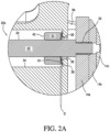
- the spring member 38 is normally in the uncompressed state illustrated in FIG. 2A .
- the brake pads 12a, 12b are out of engagement with the rotor 5, leaving a small pullback distance "D" between these two components visible in FIG. 2B .
- pressurized hydraulic fluid operates against the piston pairs 9a, 9b and 9c, 9d, extending the piston pairs against the spring force applied to them by the Belleville spring forming the spring member 38.
- the bolt shaft 24 (which is connected to the backing plate 14a via threaded end 26) is pulled toward the right-hand side of FIG. 2A .
- each controller resists the extension of the pistons 9a, 9b and 9c, 9d as it is compressed the distance "D" between the collar 30 and the annular ledge 39 from the dished shape illustrated in FIG. 2A into the more flattened shape illustrated in FIG. 3A .
- a vehicle that would otherwise have a back wheel braking engagement bias can be advantageously transformed into a vehicle having a front wheel engagement braking bias wherein the front wheels brake slightly sooner than the rear wheels.
- a front wheel braking engagement bias enhances vehicle control during a braking operation.
- such a front wheel braking engagement bias can be achieved by providing brake pad timing and retraction controller 20a, 20b and 20c, 20d on all four wheels, the difference being that the spring elements 38 used in the rear wheel calipers would be weaker than the spring elements used in the front wheel calipers.
- left-right braking wheel biases can be achieved by providing brake pad timing and retraction controller 20a, 20b and 20c, 20d exclusively on either the right or left wheels, or by providing brake pad timing and retraction controller 20a, 20b and 20c, 20d on all four wheels, the difference being that the strength of the spring elements 38 used in the right wheel calipers would be different than the strength of the spring elements 38 used in the left wheel calipers.
- the brake pad timing and retraction controller 20a, 20b and 20c, 20d also advantageously reduce brake pad vibration which can result in reduced braking efficiency as well as undesirable noises. Such vibration is caused by a resonant oscillation of the surface of the brake pads 12a, 12b against the opposing flat, annular surfaces l 8a, 18b, of the rotor 5.
- the spring element 38 in each of the brake pad timing and retraction controller 20a, 20b and 20c, 20d effectively dampens such undesirable vibration by absorbing the energy associated with the resonant oscillations of the brake pads 12a, 12b.
- the location of the maximum amplitudes of such undesirable vibration may be located via modal analysis. Because the maximum amplitude of such vibration is likely to be centrally located in the brake pads 12a, 12b concentric along the section line 1B-1B illustrated in FIG. 1A , locating each pair of brake pad timing and retraction controller 20a, 20b and 20c, 20d on opposing sides of the section line 1B-1B illustrated in FIG. 1A is likely to enhance the effectiveness of the spring elements 38 in the brake pad timing and retraction controller 20a, 20b and 20c, 20d in damping the unwanted vibrations.
- FIG. 4 illustrates the self-adjusting feature of the brake pad timing and retraction controller 20a, 20b and 20c, 20d.
- the frictional engagement between the collar 30 and the bolt shaft 24 is selected such that the collar 30 can completely compress the spring member 38 without sliding along the bolt shaft 24.
- the frictional engagement between the collar 30 and the bolt shaft 24 is insufficient to prevent the collar 30 from sliding on the shaft 24 in response to the extension force applied to the bolt shaft by its respective piston pair 9a, 9b or 9c, 9d. Consequently, the collar 30 will slide to the position necessary to flatten the spring member 38 into the position shown in FIG. 4 in order to engage the pad surface 16 against the rotor 5 as shown in the position illustrated in FIG. 3B .
- FIGS. 5A-5C illustrate how the collar 30 of the brake pad timing and retraction controller 20a, 20b and 20c, 20d may advantageously be used to adjust the stroke length of the Belleville spring 38.
- the generally cylindrical shape of the collar 30 allows this component to be reversible when assembled over the shaft 24 of the bolt 22. Accordingly, either of the two opposing sides 40 or 42 may be used to engage the Belleville spring 38 when the collar 30 is press-fitted over the shaft 24 of the bolt 22.
- one of these surfaces 40 is provided with a chamfered, dish-shaped profile that is partially complementary in shape to the Belleville spring 38 in order to shorten the stroke length of the spring 38, while the other of these surfaces 42 has a flat profile to maximize the stroke length of the Belleville spring 38.
- Such a structure advantageously allows the stroke length of the Belleville springs 38 used in the brake pad timing and retraction controller 20a, 20b and 20c, 20d to be easily shortened or lengthened to accommodate the specific type of brake caliper that the invention is incorporated in.
- the compression stroke of the spring 38 momentarily delays extension of the brake pads. This is indicated in the graph of FIG. 6 , which illustrates how the clamping force of a brake caliper with controllers 20a, 20b and 20c, 20d (solid line) is slightly delayed and reduced relative to the clamping force of a brake caliper without the controllers of the invention (dashed line). Note how zero clamping force is initially generated between the brake pads 12a, 12b and the rotor 5 for the first 100 psi of hydraulic line pressure (indicated by the distance "S"), as the first 100 psi is used to overcome the stroke of the spring 38.
- a spring 38 may be selected such that it is overcome at a lesser pressure than 100 psi or a greater pressure. Note further how the resulting clamping force indicated by the solid line lags slightly behind the clamping force generated by a caliper without controllers 20a, 20b and 20c, 20d as a result of the hold-off biasing force that the spring 38 applies against the extension force of the piston pairs 9a, 9b and 9c, 9d. As indicated previously, this slight reduction in clamping force in brake calipers incorporating the controllers of the invention is what advantageously allows the relative timing of different brakes of a vehicle to be adjusted to produce a desired timing bias between the brakes on different pairs of tires (i.e. rear vs. front, right vs.
- FIG. 7 is a graph illustrating how the force of the Belleville spring 38 used in the example of the invention varies over its compression travel.
- FIG. 7 illustrates two important characteristics of the spring 38.
- the spring 38 is a relatively "stiff' spring, requiring approximately 4.7 lbs. of force for every 0.001 inches of compression.
- Such a high-force, short compression travel advantageously allows the controllers 20a, 20b and 20c, 20d to be used in combination with high performance brake systems without compromising the short brake pedal stroke desired in such systems.
- This same characteristic also allows the controllers 20a, 20b and 20c, 20d to be made compactly with a single Belleville spring 38, which is important in view of the limited space available in the brake caliper 3.
- the substantial linearity of the force/distance property of the spring 38 results in a modified clamping force curve (see FIG. 6 ) that substantially tracks the unmodified clamping force curve with respect to the line pressure generated by the master cylinder of the brake system.
- the brake assembly shown in FIG. 16 includes features of those described previously with reference to the embodiment shown in FIG. 1 .
- a brake assembly 1' including the brake caliper 3' constructed in accordance with embodiments disclosed herein below.
- the caliper 3' together with a rotor 5' are attached to a wheel hub (not shown) which may be the wheel hub of an automotive vehicle.
- the brake caliper 3' includes a housing 7' in which two pairs of opposing hydraulic caliper pistons are slidably mounted within cylinders (not shown).
- Opposing brake pads 12a', 12b' may each include a backing plate 14a', 14b' and an underlayer that secures a layer of pad material 14c' to the backing plate 14a'.
- the opposing brake pads 12a', 12b' are mounted on the ends of the opposing caliper pistons via the backing plate 14a'.
- the brake pads 12a', 12b' each have an engagement surface 16' which is adjacent to and engageable with one of the flat, opposing annular engagement surfaces 18a', 18b' of the rotor 5' as is best shown in FIG. 16 .
- hydraulic pistons 9a, 9b and 9c, 9d are only one example of reacting members which may be used to extend and retract the brake pads 12a', 12b' with respect to the rotor 5'.
- the pads 12a', 12b' may be extended and retracted by an air actuated piston, by a mechanical arrangement of cams and levers, or electrically via solenoids for example.
- a brake pad timing and retraction controller 20a' comprises a bolt shaft 22' having a threaded end portion 26' for connection with the backing plate 14a' of the brake pad 12a'.
- the caliper retraction collar 30' is preferably press fitted upon the shaft 22'.
- the caliper retraction collar 30' preferably includes first and second surfaces 40' and 42' as previously described.
- a spring 38' preferably in the form of a Belleville spring, is situated on the bolt shaft 22' adjacent the caliper retraction collar 30'.
- the bolt shaft 22' extends through a bore 36' in the housing 7'.
- the bore 36' defines in part a rim portion 37 of the housing 7' adjacent the shaft 22'.
- a first ring 202 and a second ring 204 are interposed between the spring 38' and the rim portion 37 of the housing 7'.
- the housing rim portion 37' the first and second rings 202, 204 establish a stop with respect to displacement (compression) of the Belleville spring 38'.
- the first and second rings 202, 204 also allow for a misalignment of the brake pad to the caliper without damaging the bolt 22'.
- the embodiment shown therein further includes a lock-connection 206 between the threaded end portion 26' of the bolt 22' and the backing plate 14a'.
- the lock-connection 206 comprises a first engaging component 208 in the form of a leading zone of standard threading on the end portion 26'of the bolt 22', and a locking component 210 comprising a trailing zone of lock threading along the end portion 26' of the bolt shaft 22'.
- the lock-connection further comprises a receiver component 212 preferably in the form of a threaded bore in the backing plate 14a' of a brake pad 12a'.
- a standard threading extends throughout the extent of the threaded bore 212.
- the engaging component 208 comprises a leading zone of matching standard threading, which is "leading" in the sense that it is the first in time to engage the standard threading of the threaded bore receiver 212, which arrangement assures proper alignment of the shaft 22' with backing plate 14a' (and the brake pad 12) before the locking component 210 is engaged.
- a lock-connection 206 is established, wherein the shaft 22' with backing plate 14a' are properly aligned and locked together.
- the locking component 210 of the lock-connection 206 is counteractive against the effects of vibration, heat and torques typically imposed upon the connection 206 during a braking action, especially those effects tending to rotate the engaging component 208 out of a full and secure engagement.
- the locking component 210 of the lock-connection 206 comprises not only a trailing zone of lock threading 210 on the end portion 26' of the shaft 22' but also a trailing zone of lock threading 210' within the threaded bore 212 of the backing plate 14a.
- the locking component 210 may be disposed only along the threaded bore portion 210' of the backing plate 14a'.
- leading threading zone 208 on the shaft 22' and/or a leading threading zone 208' along the threaded bore 212 engages first so as to align the shaft 22' and the backing plate 14a', whereupon the locking component 210 then engages to complete and secure the lock-connection 206.
- a locking threading extends throughout the extent of the threaded bore 212 and a standard threading extends throughout the extent of the threaded, shaft end portion 26'.
- a suitable locking thread for application in this embodiments include a lock threading from the Spiralock Corporation that transforms a standard internal thread profile into a self-locking female thread form with the addition of a 30° wedge ramp at the root of the female thread.
- This unidirectional locking feature, called Spiralock ® is compatible with standard 60° male thread fasteners.
- the end portion of the shaft 22' is constructed of an alloy, hardened or otherwise treated to be more resistant to thread stripping than the material (or treatment) selected for the receiver portion 212 of the backing plate 14a'. Accordingly, in a change of of brake pads, any occurrence of unintended stripping to overcome the lock-connection 206 will be incurred along threads 212 of the backing plate 14a, which is being replaced.
- a flanged binding post (threaded insert) 270 is fitted into a bore 280 in the backing plate 14a' from a backside 274 of the backing plate 14a'.
- the flanged binding post 270 includes an axially directed, threaded bore 208 and a flange 272 adapted to be brought into a surface to surface contact with the backside 274 of the backing plate 14a'.
- the engaging component of the lock-connection 206 is in the form of the internal threading along the bore 208 of the flanged binding post 270 and the locking component 210 comprises a tightening of the flange 272 of the flanged binding post 270 against the backside surface 274 of the backing plate 14a' upon threading of the end portion 26'of the bolt shaft 22' into the flanged binding post 270.
- the internal threading 208 of the flanged binding post 270 extends through the entire length of the flanged binding post 270.
- the threaded end portion 26' of the shaft 22' will continue to thread into the threaded insert 270 until threaded insert 270 urges its flange 272 against the backside surface 274 of the backing plate 14a' with sufficient force to be counteractive against the effects of vibration, heat and torques typically imposed upon the connection 206 during a braking action, especially those effects tending to rotate the components 208 out of a full and secure engagement.
- the threading of the threaded end portion 26'of the shaft 22' is allowed to continue to until a shoulder 276 of the shaft 22' contacts an opposing rim 278 of the threaded insert 270, whereupon further threading of the shaft 22'into the threaded insert 270 is limited so that a sufficient lock-connection 206 is consistently achieved.
- the threaded insert 270 may be press fitted into a bore 280 provided in the backing plate 14a'.
- a threaded connection may be used along the bore 280 in lieu of a press-fitted connection.
- a zone of trailing lock threading as taught in reference to FIG. 8.A, 8.B and 8.C is employed along any of the threaded connections of the immediate embodiment to further secure the lock-connection 206.
- a lock-connection 206 between the backing plate 14a' and the shaft 22' comprises an engaging component 208 in the form of a fit between a bore 300 provided in the backing plate 14a' and the end portion 26' of shaft 22' and a locking component 210 comprising a screw-thread lock operative from an outer rim portion 302 of the backing plate 14a'.
- the locking component 210 comprises a threaded screw body 304 in a threaded bore 307, wherein the threaded bore 307 is open to the outer rim 302 and is oriented orthogonally with respect to the longitudinal axis of the bore 300.
- a shoulder 306 is provided at the base of the end portion 26'of the shaft 22'which is brought in to contact with a rim 308 of the backing plate 14a' so as to register proper placement of the shaft 22'before tightening of the threaded body 304.
- a lock-connection 206 is achieved having sufficient locking force to be counteractive against the effects of vibration, heat and torques typically imposed upon the connection 206 during a braking action, especially those effects tending to rotate the engaging component 208 out of a full and secure engagement.
- the engaging portion 208 assures a desired alignment of the shaft 22' before locking of the locking component 210 and comprises between the bore 300 in the backing plate 14a' and the end portion 26' of the shaft 22' a threaded fit including a zone of lock threading as taught in reference to FIG. 8A, 8B and 8C to further secure the lock-connection 206.
- a lock-connection 206 between the backing plate 14a' and the shaft 22' comprises an engaging component 208 in the form of a fit between a bore 300 provided in the backing plate 14a' and conforming (mating) end portion 26' of shaft 22' and a locking component 210 in the form of a retaining clip 320 disposed within opposing annular recesses 322, 324 provided in the bore 300 in the backing plate 14a' and in the end portion 26' of the shaft 22', respectively.
- the retaining clip (split-ring) 320 has a rectangular cross section and is ring-like, but for an annular break 326, which allows the retaining clip 320 to be circumferentially compressed.
- the retaining clip 320 is resilient and metallic.
- the retaining clip 320 is carried upon a trailing portion of the end portion 26' of the shaft 22' such that upon entry of the shaft end portion 26'into the bore 300 in the backing plate 14a', the walls of the bore 300 compresses the retaining clip 320 fully into the recess 324 provided in the end portion 26' until the shaft 22' is moved into a position where the annular recesses 322 and 324 are mutually opposed, whereupon the retaining clip 320 expands into the space defined between the opposing annular recesses 322 324 to complete the lock-connection 206.
- the retaining clip 320 may be carried within the recess 322 provided in the bore 300 of the backing plate 14a', in which case, upon insertion of the end portion 26'of the shaft 'into the bore 300 of the backing plate 14a', the end portion 26'urges the resilient ring 320 radially outwardly into space provided by the annular recess 322 in the backing plate 14a' until the recesses 322, 324 come into an opposing relation whereupon the retaining clip 320 is released and completes the lock-connection 206.
- the retaining ring 320 Upon completion of the lock-connection 206, the retaining ring 320 provides sufficient locking force to be counteractive against the effects of vibration, heat and torques typically imposed upon the connection 206 during a braking action, especially those effects tending to rotate the engaging component 208 out of a full and secure engagement.
- the engaging portion 208 assures a desired alignment of the shaft 22' before locking of the locking component 210.
- the engaging portion 208 comprises between the bore 300 in the backing plate 14a' and the end portion 26' of the shaft 22' a threaded fit therebetween.
- the engaging component 208 comprises a threaded fit and it includes a zone of lock threading as taught in reference to FIGS. 8A, 8B and 8C to further secure the lock-connection 206.
- a lock-connection 206 between the backing plate 14a' and the shaft 22' comprises an engaging component 208 in the form of a fit between a bore 300 provided in the backing plate 14a' and a conforming (mating) end portion 26' of shaft 22' and a locking component 210 in the form of a self-locking key arrangement 330 provided between the bore 300 in the backing plate 14a' and in the end portion 26' of the shaft 22'.
- the bore 300 and the backing plate 14a' is provided with a slot 332 having a transverse slot portion 331 and a longitudinal slot portion 334 extending from the transverse slot portion 331 to a leading (front) side 336 of the backing plate 14a'.
- a radially extending key 338 is provided on the end portion 26', which is sized to slidingly travel along the longitudinally extending slot portion 334 as the shaft 22 is inserted into the slotted bore 300, until the key 338 arrives at the transverse slot portion 321, whereupon the shaft 22' is rotated and the key 338 enters and establishes a close locking fit with the transverse slot portion 331.
- the transverse slot portion 331 accommodates a quarter turn of the shaft 22', although it is contemplated that the transverse slot may be longer or shorter to establish a different length of locking turn such as a half locking turn or a three-quarter locking turn or the like.
- a lock-connection 206 is established with sufficient locking effect to be counteractive against the effects of vibration, heat and torques typically imposed upon the connection 206 during a braking action, especially those effects tending to rotate the component 208 out of a full and secure engagement.
- the slot 332 may be provided on the end portion 26'of the shaft 22'and the key 338 is provided at a location along the bore 300 of the backing plate 14a.
- the key 338 may be spring loaded and present an inclined, leading face such that upon insertion or threading of the shaft end portion 26' into the bore 300, the key 338 is retracted to allow further insertion and/or threading until such time that the key 338 enters a transversely directed slot 332 (331).
- the slot 332 is without a longitudinal component.
- the engaging portion 208 assures a desired alignment of the shaft 22' before locking of the locking component 210, and may comprise a close sliding fit between the bore 300 in the backing plate 14a' and the end portion 26' of the shaft 22'.
- the transverse slot 331 is located at a midpoint along the bore 300 in the backing plate 14a', but other locations along the bore 300 are contemplated.
- a lock-connection 206 between the backing plate 14a' and the shaft 22' comprises an engaging component 208 in the form of a fit between a bore 300 provided in the backing plate 14a' and a conforming (mating) end portion 26' of shaft 22' and a locking component 210 in the form of a quick release pin 340 operative between the bore 300 in the backing plate 14a' and the end portion 26' of the shaft 22'.
- a spring loaded ball 342 is provided at a location along the end portion 26' of the shaft 22', and the bore 300 in the backing plate 14a' is provided with an annular recess 344, the latter being sized to at least partially receive the body of the spring loaded ball 342 whereby the engagement between end portion 26' of the shaft 22' becomes locked against the effects of vibration, heat and torques typically imposed upon the connection 206 during a braking action, especially those effects tending to rotate the component 208 out of a full and secure engagement.
- the spring loaded ball 342 Upon an initial insertion or threading of the end portion 26' into the bore 300, the spring loaded ball 342 is pushed into the recess 346 so that the insertion and/or threading can continue until the spring loaded ball 342 arrives at the location of the recess 344 in the bore 300.
- the ball element of the spring loaded ball 342 may have a rectangular shape instead of the spherical shape of the embodiment shown in the FIGS. 14.A and 14.B .
- the spring loaded ball 342 may be established at a location along the bore 300 of the backing plate 14a' and the recess 344 may be located along the end portion 26'of the shaft 22'.
- the engaging portion 208 assures a desired alignment of the shaft 22' before locking of the locking component 210, and comprises between the bore 300 in the backing plate 14a' and the end portion 26' of the shaft 22' a threaded fit therebetween. It is also contemplated that the threading includes a zone of lock threading as taught in reference to FIGS. 8A, 8B and 8C to further secure the lock-connection 206.
- a lock-connection 206 between the backing plate 14a' and the shaft 22' comprises an engaging component 208 in the form of an initial friction fit between the bore 300 provided in the backing plate 14a' and a conforming (mating) end portion 26' of shaft 22'and a locking component 210 in the form of a press fit 350 being established between the bore 300 and the end portion 26' of the shaft 22' after a desired alignment of the shaft end portion 26' is achieved using the initial friction fit.
- the engaging component further comprises a shoulder 352 provided at a trailing location along the shaft portion 26' of the shaft 22' which comes into contact with a rim of the bore 300 upon a complete insertion of the shaft 22' into the bore 300.
- the contact registers the longitudinal placement of the shaft 22' relative to the backplate 14a' so as to achieve a consistent lock-connection 206.
- a lock-connection 206 between the backing plate 14a'and the shaft 22' comprises an engaging component 208 in the form of a fit between a threaded bore 300 provided in the backing plate 14a' and a mating end portion 26'of the shaft 22'and a locking component 210 in the form of a locking (safety) wire 504 directed through a transverse channel 510 provided in the shaft 22' and through a second bore 304 provided in the backing plate 14a' adjacent the bore 300.
- the fit between the shaft end portion 26' and the bore 300 is threaded.
- the transverse channel 510 is preferably located adjacent but spaced from the end portion 26' of the shaft 22'such that it locates in a space between the backing plate 14a'and the housing 7'.
- opposite ends of the safety wire are directed through the channel 510 and the second bore 304 and then wound together to remove slack and to produce a desired amount of tension in the locking wire 504.
- the routing of the wire 504 through and about the shaft 22' at and about the transverse channel 510 is such that upon winding (tightening) of the locking wire 504, tension in the wire 504 is in a direction tending to tighten the threaded connection between the threaded bore 300 of the backing plate 14a' and the threaded end portion 26' of the shaft 22'.
- a lock-connection 206 is established which is counteractive against the effects of vibration, heat and torques typically imposed upon the connection 206 during a braking action, especially those effects tending to rotate the engaging component 208 out of a full and secure engagement.
- the engaging component 208 of this embodiment comprises a lock threading as taught in reference to FIG. 8.A, 8.B and 8.C .
- locking component 210 of this embodiment could be used in addition to the respective locking components 210 of any of the preceding embodiments or in lieu of the respective locking components 210 of any of the embodiments of figures 10 to 14 .
- an embodiment includes at least one stop ring interposed between the spring 38 and the rim portion 37 of the housing 7'.
- a first ring 202 and a second ring 204 is provided between the spring and the housing rim portion 37 so as to establish a stop with respect to deflection (displacement) of the spring 38.
- the caliper retraction collar 30' is urged against and deflects (displaces) the spring 38 toward the first ring 202 such that the spring 38 may come into a surface to surface contact against at least portions of an annular surface 410 of the first ring 202.
- the annular surface 410 of the first ring 202 is orthogonal relative to the shaft 22', such that upon full deflection of the spring 38, the spring assumes a more orthogonal relation with respect to the shaft 22'.
- the first ring 202 is slidingly fitted upon the shaft 22' such that it does not impede the sliding movement of the shaft 22' relative to the retraction collar 30 as described previously.
- the second ring 204 is disposed about the shaft 22' with clearance and an outer portion of the second ring 204 abuts the housing rim portion 37.
- the first and second rings 202 and 204 are mutually interfaced about frusto-conical surfaces 420, 422 such that compression of the first and second rings 202, 204 by the spring 38 centers the second ring 204 concentrically about the bolt shaft 22', with clearance.
- the first ring 202 may come in sets for selection and placement of a particular ring 202 on the shaft 22'according to a desired degree of deflection and/or size of the spring 38.
- a first ring 202 may be provided with a conical surface 410 which limits the deflection of the spring 38 by an amount less than a ring 202 having orthogonal annular surface 410.
- a particulr ring 202 may be sized radially to accommodate a larger or smaller Belleville spring 38.
- the surface to surface contact of the first ring 202 with the shaft 22'and the surface to surface contact of the second ring 202 with the housing portion 37 can help distribute loads, torques and vibrations that arise during braking operations.
- the first and second rings also allow the shaft 22' to angularly shift in instances when operation of the brake may cause the orientation of the brake pad 12a' and its backing plate 14a' to skew momentarily.
- the first and second rings 202, 204 continue to provide a stop to spring movement as previously described while also alleviating (distributing) loads and bending moments upon the shaft 22'as a result of the shifting.
- the radial clearance between the second ring 204 and the shaft 22' also accommodates relative movement between the two during such shifting.
- the surface-to-surface contact between the first ring 202 and the shaft 22' helps distribute loads along the shaft 22'.
Landscapes
- Engineering & Computer Science (AREA)
- General Engineering & Computer Science (AREA)
- Mechanical Engineering (AREA)
- Braking Arrangements (AREA)
Claims (7)
- Bremsbelag (12a), der in Verbindung mit einem Bremsbelag-Rückzugssystem verwendet werden kann, wobei der Bremsbelag (12a) umfasst:
ein Reibungsmaterial, das an einer Bremsankerplatte (14a) fixiert ist, wobei die Bremsankerplatte (14a) eine Sperrverbindung (206) umfasst, die zwischen dem Bremsbelag (12a) und einem Endteil einer Steuerwelle (22') betätigt werden kann, wobei die Sperrverbindung (206) eine Eingreifkomponente (208`), die betätigbar ist, um eine Ausrichtung der Steuerwelle (22') in Bezug auf den Bremsbelag (12a) herzustellen, und eine Sperrkomponente (210'), die betätigbar ist, um die Steuerwelle (22') in der Ausrichtung zu sperren, umfasst, wobei die Sperrverbindung (206) einer Vibration, einer Wärme und/oder einem Drehmoment, die durch die Bremsbetätigung verursacht werden, entgegenwirkt, dadurch gekennzeichnet, dass die Sperrverbindung (206) weiterhin eine Bohrung (212, 280) in der Bremsankerplatte (14a) mit einem ersten Gewinde umfasst, wobei die Bohrung (212, 280) ausgebildet ist zum Aufnehmen des Endteils der Steuerwelle (22'), wobei die Eingreifkomponente (208') einen vorderen Gewindebereich an dem Wellenendteil (26') in Entsprechung zu dem Gewinde der ersten Bohrung umfasst und wobei die Sperrkomponente (210') einen hinteren Sperrgewindebereich an dem Endteil (26') der Steuerwelle (22') umfasst. - Bremsbelag (12a) nach Anspruch 1, wobei die Bohrung (280) in der Bremsankerplatte (14a') ausgebildet ist zum Aufnehmen eines geflanschten Verbindungszapfens (270) mit einer Presspassung.
- Bremsbelag (12a) nach Anspruch 1, wobei die Bohrung (280) in der Bremsankerplatte (14a') mit einem Gewinde versehen ist, sodass sie ausgebildet ist zum schraubenden Aufnehmen des geflanschten Verbindungszapfens.
- Bremsbelag (12a) nach Anspruch 1, wobei der Eingreifteil (208') eine Passung zwischen einer in der Bremsankerplatte (14a') vorgesehenen Bohrung (300) und dem Wellenendteil (26') umfasst und die Sperrkomponente (210') eine Sperrschraube umfasst.
- Bremsbelag (12a) nach Anspruch 1, wobei der Eingreifteil eine Passung zwischen einer in der Bremsankerplatte (14a`) vorgesehenen Bohrung (300) und dem Wellenendteil (26') umfasst und die Sperrkomponente (210) einen Haltering (320) umfasst.
- Bremsbelag (12a) nach Anspruch 1, wobei der Eingreifteil eine Passung zwischen einer in der Bremsankerplatte (14a) vorgesehenen Bohrung (300) und dem Wellenendteil (26') umfasst und die Sperrkomponente (210) einen Schlitz (332) und einen Keil (338), die wenigstens entlang eines Teils der Bohrung (300) betätigt werden können, umfasst, wobei der Keil (338) entlang des Schlitzes in einer Querrichtung in eine Sperrbeziehung zwischen dem Wellenendteil (26') und der Bremsankerplatte (14a') bewegt werden kann.
- Bremsanordnung (1), umfassend:eine Bremsbelag-Timing/Rückzug-Steuereinrichtung (20a, 20b, 20c, 20d), die eine Steuerwelle (22') mit einem Endteil umfasst, undeinen Bremsbelag (12a) gemäß Anspruch 1 oder 2.
Applications Claiming Priority (2)
| Application Number | Priority Date | Filing Date | Title |
|---|---|---|---|
| US201562253499P | 2015-11-10 | 2015-11-10 | |
| PCT/US2016/061309 WO2017083507A1 (en) | 2015-11-10 | 2016-11-10 | Brake caliper with brake pad timing and retraction controller with lock-connection |
Publications (2)
| Publication Number | Publication Date |
|---|---|
| EP3374657A1 EP3374657A1 (de) | 2018-09-19 |
| EP3374657B1 true EP3374657B1 (de) | 2024-01-03 |
Family
ID=57349168
Family Applications (1)
| Application Number | Title | Priority Date | Filing Date |
|---|---|---|---|
| EP16798367.5A Active EP3374657B1 (de) | 2015-11-10 | 2016-11-10 | Bremsbelag mit einem bremsbelagtaktungs- und -rückzugsteuergerät mit sperrverbindung |
Country Status (3)
| Country | Link |
|---|---|
| US (1) | US10253835B2 (de) |
| EP (1) | EP3374657B1 (de) |
| WO (1) | WO2017083507A1 (de) |
Families Citing this family (7)
| Publication number | Priority date | Publication date | Assignee | Title |
|---|---|---|---|---|
| IT201700073192A1 (it) | 2017-06-29 | 2018-12-29 | Itt Italia Srl | Dispositivo di calibrazione automatica di una pastiglia per freni |
| DE102018104569A1 (de) * | 2018-02-28 | 2019-08-29 | Knorr-Bremse Systeme für Nutzfahrzeuge GmbH | Nachstellvorrichtung für eine Scheibenbremse |
| CN109372909A (zh) * | 2018-04-08 | 2019-02-22 | 九江精密测试技术研究所 | 基于杠杆微动原理回转轴的机械锁紧装置 |
| FR3088394B1 (fr) * | 2018-11-08 | 2020-11-20 | Tallano Tech | Systeme de captation de particules de frein a disque ferroviaire avec bague d'etancheite et mecanisme de rappel |
| JP7124686B2 (ja) * | 2018-12-17 | 2022-08-24 | トヨタ自動車株式会社 | ディスクブレーキ装置 |
| DE102019124442A1 (de) * | 2019-09-11 | 2021-03-11 | Zf Active Safety Gmbh | Bremsbelaganordnung |
| US12560210B2 (en) * | 2023-07-18 | 2026-02-24 | Bendix Commercial Vehicle Systems Llc | Air disc brake system with caliper retraction and methods for the use and assembly thereof |
Citations (1)
| Publication number | Priority date | Publication date | Assignee | Title |
|---|---|---|---|---|
| GB2399607A (en) * | 2003-03-18 | 2004-09-22 | Trw Ltd | Wear adjuster for brake shoe |
Family Cites Families (54)
| Publication number | Priority date | Publication date | Assignee | Title |
|---|---|---|---|---|
| US2551251A (en) * | 1946-02-08 | 1951-05-01 | Bendix Aviat Corp | Automatically adjusting brake |
| US2536269A (en) * | 1946-02-21 | 1951-01-02 | Bendix Aviat Corp | Automatically adjusting brake |
| US2711801A (en) * | 1951-08-07 | 1955-06-28 | Rockwell Spring & Axle Co | Detachable brake shoe |
| US2830680A (en) * | 1955-06-17 | 1958-04-15 | Goodyear Tire & Rubber | Automatic brake adjustor for brake lining wear |
| FR1152453A (fr) | 1956-06-21 | 1958-02-18 | Bendix Sa | Perfectionnements aux freins à disques |
| US2997138A (en) | 1959-04-28 | 1961-08-22 | Raymond E Astle | Wear compensating brake |
| US3243017A (en) | 1964-07-02 | 1966-03-29 | Gen Motors Corp | Hydraulically operable disc brakes for motor vehicles |
| US3403755A (en) | 1967-04-27 | 1968-10-01 | Int Harvester Co | Brake return and automatic adjustment means |
| GB1262263A (en) | 1968-04-05 | 1972-02-02 | Girling Ltd | Improvements in or relating to vehicle disc brakes |
| US3554334A (en) | 1968-06-17 | 1971-01-12 | Keizo Shimano | Hydraulic bicycle brake system |
| US3532190A (en) | 1968-10-14 | 1970-10-06 | Int Harvester Co | Automatic adjustor for disc brakes |
| DE1920128A1 (de) | 1969-04-21 | 1970-11-05 | Lenze Kg Maschf Hans | Selbsttaetige Nachstellvorrichtung fuer Zweischeibenoder Lamellen-Federkraft-Kupplungen oder -Bremsen mit elektromagnetischer Loesung der Kupplung bzw. Lueftung der Bremse |
| BE756314A (fr) | 1969-09-19 | 1971-03-18 | Ciba Geigy | Nouveaux agents pesticides du type des phenylurees, leur procede de preparation et leur emploi |
| US3618714A (en) | 1970-05-19 | 1971-11-09 | Gen Motors Corp | Disc brake friction pad adjusting device |
| JPS4729078U (de) | 1971-04-23 | 1972-12-02 | ||
| JPS4733584U (de) | 1971-05-18 | 1972-12-14 | ||
| GB1495701A (en) | 1973-12-07 | 1977-12-21 | Twiflex Couplings | Industrial disc brakes |
| JPS5333097Y2 (de) | 1974-05-20 | 1978-08-15 | ||
| JPS5914649B2 (ja) | 1975-03-28 | 1984-04-05 | トヨタ自動車株式会社 | ピストン−シリンダ装置およびこれを用いたデイスクブレ−キ装置 |
| GB1545207A (en) | 1975-08-09 | 1979-05-02 | Girling Ltd | Hydraulically-operated disc brakes for vehicles |
| US4057127A (en) | 1975-11-06 | 1977-11-08 | J. C. Penney Company, Inc. | Safety actuating device adapted for two wheeled vehicles |
| US4191677A (en) * | 1977-10-21 | 1980-03-04 | Federal Screw Works | Self-locking threaded fastener product |
| GB1600998A (en) | 1978-05-09 | 1981-10-21 | Dormer R J | Disc brake piston retraction means |
| US4378863A (en) | 1979-08-30 | 1983-04-05 | Lucas Industries Limited | Automatic adjuster for hydraulic brake actuator |
| JPS6018677Y2 (ja) | 1979-10-11 | 1985-06-06 | トヨタ自動車株式会社 | ピンスライド型デイスクブレ−キ |
| FR2478761A1 (fr) * | 1980-03-18 | 1981-09-25 | Dba | Frein a disque |
| JPS6135791Y2 (de) | 1980-04-07 | 1986-10-17 | ||
| US4382491A (en) | 1980-08-11 | 1983-05-10 | Hurst Performance, Inc. | Drag free disc brake assembly having automatically adjusting caliper |
| JPS6128496Y2 (de) | 1980-08-27 | 1986-08-23 | ||
| JPS5757932A (en) | 1980-09-24 | 1982-04-07 | Nissin Kogyo Kk | Disc brake for vehicle |
| US4345674A (en) | 1980-09-29 | 1982-08-24 | International Harvester Co. | Disc brake pad retractor |
| US4662483A (en) * | 1985-10-28 | 1987-05-05 | Boeck Leon W | Disc brake retractor |
| US4712654A (en) | 1986-12-09 | 1987-12-15 | Allied Corporation | Brake assembly with multiple adjustability |
| JP2573955B2 (ja) | 1987-07-30 | 1997-01-22 | 株式会社トプコン | 測色装置 |
| JPH0511390Y2 (de) | 1988-06-03 | 1993-03-22 | ||
| DE3870882D1 (de) | 1988-12-14 | 1992-06-11 | Mayr Christian Gmbh & Co Kg | Selbsttaetige nachstellvorrichtung fuer elektromagnetisch betaetigte kupplungs- und/oder bremsaggregate. |
| US5186284A (en) | 1991-05-31 | 1993-02-16 | Case Corporation | Fail safe self-adjusting disc brake |
| US5613579A (en) * | 1992-11-16 | 1997-03-25 | Westinghouse Air Brake Company | Latch locking spring clip for retaining an insertable brake shoe lining on a disc brake head |
| DE4304616A1 (de) | 1993-02-16 | 1994-08-18 | Daimler Benz Ag | Scheibenbremse für die Räder eines Kraftfahrzeuges |
| JPH0669460U (ja) | 1993-03-09 | 1994-09-30 | 日産自動車株式会社 | ディスクブレーキのピストン復帰構造 |
| US5427211A (en) | 1994-01-10 | 1995-06-27 | Deere & Company | Piston stop pin for a hydraulic brake |
| US5549181A (en) | 1994-09-13 | 1996-08-27 | Kelsey-Hayes Company | Brake shoe retractor clip for disc brake assembly |
| BR9711849A (pt) | 1996-10-03 | 1999-08-24 | Toyota Motor Co Ltd | Sistema de frenagem que inclui freio de disco acionado por motor equipado com mecanismo auto-servo |
| JP2000088014A (ja) | 1998-09-09 | 2000-03-28 | Sumitomo Electric Ind Ltd | 浮動型ディスクブレーキ |
| US6394236B1 (en) | 2000-03-20 | 2002-05-28 | Shimano, Inc. | Cable disc brake |
| US6378665B1 (en) | 2000-06-30 | 2002-04-30 | Kelsey-Hayes Company | Pad retraction spring for disc brake assembly |
| US6397983B1 (en) | 2001-02-23 | 2002-06-04 | Akebono Corporation North America | Automatic adjustment for disc brake pad |
| US6766886B2 (en) | 2001-04-26 | 2004-07-27 | Caterpillar Inc. | Self-adjusting braking apparatus |
| GB0122970D0 (en) * | 2001-09-25 | 2001-11-14 | Trw Ltd | Retraction mechanism for disc brake assembly |
| KR100579743B1 (ko) | 2004-06-19 | 2006-05-15 | 현대자동차주식회사 | 차량용 브레이크 캘리퍼의 피스톤 구조 |
| ATE390576T1 (de) | 2004-12-14 | 2008-04-15 | Volvo Constr Equip Holding Se | Anordnung zur reduzierung einer drehgeschwindigkeit eines rotierenden glieds |
| BRPI0822925A2 (pt) * | 2008-07-07 | 2015-06-23 | Deere & Co | Conjunto retrator do freio para um veículo. |
| US9512892B2 (en) | 2009-10-26 | 2016-12-06 | Performance Friction Corporation | Brake caliper with brake pad timing and retraction controller |
| US8425168B2 (en) * | 2010-09-13 | 2013-04-23 | Flow-Rite Controls, Ltd. | Locking threaded fastener |
-
2016
- 2016-11-10 US US15/348,463 patent/US10253835B2/en active Active
- 2016-11-10 WO PCT/US2016/061309 patent/WO2017083507A1/en not_active Ceased
- 2016-11-10 EP EP16798367.5A patent/EP3374657B1/de active Active
Patent Citations (1)
| Publication number | Priority date | Publication date | Assignee | Title |
|---|---|---|---|---|
| GB2399607A (en) * | 2003-03-18 | 2004-09-22 | Trw Ltd | Wear adjuster for brake shoe |
Also Published As
| Publication number | Publication date |
|---|---|
| US20170159734A1 (en) | 2017-06-08 |
| US10253835B2 (en) | 2019-04-09 |
| EP3374657A1 (de) | 2018-09-19 |
| WO2017083507A1 (en) | 2017-05-18 |
Similar Documents
| Publication | Publication Date | Title |
|---|---|---|
| US10253835B2 (en) | Brake caliper with brake pad timing and retraction controller with lock-connection | |
| US10001187B2 (en) | Brake caliper with brake pad timing and retraction controller | |
| US8127897B2 (en) | Caliper brake system | |
| US7182182B2 (en) | Drum brake and brake shoe for one such brake | |
| US5246093A (en) | Drum brake assembly | |
| CN104271978A (zh) | 带有复位装置的盘式制动器和制动衬片 | |
| AU717900B2 (en) | Play adjustment | |
| US5921356A (en) | Adjustable parking brake integrated with service brake | |
| US4865161A (en) | Sliding saddle disc brake | |
| EP4063682B1 (de) | Bremsanordnung | |
| US20190085926A1 (en) | Brake pad retraction | |
| WO2016005372A1 (de) | Führungssystem für einen bremskolben einer kraftfahrzeugscheibenbremse | |
| US9180842B2 (en) | Disc brakes | |
| EP0105977B1 (de) | Automatische Bremsnachstellvorrichtung | |
| GB1563405A (en) | Disc brake caliper assembly | |
| US4051925A (en) | Disc brakes for vehicles including a screw-threaded draw bar assembly | |
| US20170016501A1 (en) | Brake pad retraction | |
| US3760908A (en) | Disc brakes for vehicles | |
| GB1567005A (en) | Disc brakes for vehicles | |
| JP4668772B2 (ja) | ディスクブレーキ用板金製サポートの製造方法 | |
| JP2010174932A (ja) | 車両用ドラムブレーキ |
Legal Events
| Date | Code | Title | Description |
|---|---|---|---|
| STAA | Information on the status of an ep patent application or granted ep patent |
Free format text: STATUS: UNKNOWN |
|
| STAA | Information on the status of an ep patent application or granted ep patent |
Free format text: STATUS: THE INTERNATIONAL PUBLICATION HAS BEEN MADE |
|
| PUAI | Public reference made under article 153(3) epc to a published international application that has entered the european phase |
Free format text: ORIGINAL CODE: 0009012 |
|
| STAA | Information on the status of an ep patent application or granted ep patent |
Free format text: STATUS: REQUEST FOR EXAMINATION WAS MADE |
|
| 17P | Request for examination filed |
Effective date: 20180605 |
|
| AK | Designated contracting states |
Kind code of ref document: A1 Designated state(s): AL AT BE BG CH CY CZ DE DK EE ES FI FR GB GR HR HU IE IS IT LI LT LU LV MC MK MT NL NO PL PT RO RS SE SI SK SM TR |
|
| AX | Request for extension of the european patent |
Extension state: BA ME |
|
| DAV | Request for validation of the european patent (deleted) | ||
| DAX | Request for extension of the european patent (deleted) | ||
| STAA | Information on the status of an ep patent application or granted ep patent |
Free format text: STATUS: EXAMINATION IS IN PROGRESS |
|
| 17Q | First examination report despatched |
Effective date: 20211022 |
|
| RIC1 | Information provided on ipc code assigned before grant |
Ipc: F16D 127/02 20120101ALN20230524BHEP Ipc: F16D 65/54 20060101ALI20230524BHEP Ipc: F16D 65/095 20060101AFI20230524BHEP |
|
| GRAP | Despatch of communication of intention to grant a patent |
Free format text: ORIGINAL CODE: EPIDOSNIGR1 |
|
| STAA | Information on the status of an ep patent application or granted ep patent |
Free format text: STATUS: GRANT OF PATENT IS INTENDED |
|
| RIC1 | Information provided on ipc code assigned before grant |
Ipc: F16D 127/02 20120101ALN20230605BHEP Ipc: F16D 65/54 20060101ALI20230605BHEP Ipc: F16D 65/095 20060101AFI20230605BHEP |
|
| INTG | Intention to grant announced |
Effective date: 20230712 |
|
| GRAS | Grant fee paid |
Free format text: ORIGINAL CODE: EPIDOSNIGR3 |
|
| GRAA | (expected) grant |
Free format text: ORIGINAL CODE: 0009210 |
|
| STAA | Information on the status of an ep patent application or granted ep patent |
Free format text: STATUS: THE PATENT HAS BEEN GRANTED |
|
| AK | Designated contracting states |
Kind code of ref document: B1 Designated state(s): AL AT BE BG CH CY CZ DE DK EE ES FI FR GB GR HR HU IE IS IT LI LT LU LV MC MK MT NL NO PL PT RO RS SE SI SK SM TR |
|
| REG | Reference to a national code |
Ref country code: GB Ref legal event code: FG4D |
|
| REG | Reference to a national code |
Ref country code: CH Ref legal event code: EP |
|
| REG | Reference to a national code |
Ref country code: DE Ref legal event code: R096 Ref document number: 602016085153 Country of ref document: DE |
|
| REG | Reference to a national code |
Ref country code: IE Ref legal event code: FG4D |
|
| REG | Reference to a national code |
Ref country code: LT Ref legal event code: MG9D |
|
| PG25 | Lapsed in a contracting state [announced via postgrant information from national office to epo] |
Ref country code: ES Free format text: LAPSE BECAUSE OF FAILURE TO SUBMIT A TRANSLATION OF THE DESCRIPTION OR TO PAY THE FEE WITHIN THE PRESCRIBED TIME-LIMIT Effective date: 20240103 |
|
| PG25 | Lapsed in a contracting state [announced via postgrant information from national office to epo] |
Ref country code: ES Free format text: LAPSE BECAUSE OF FAILURE TO SUBMIT A TRANSLATION OF THE DESCRIPTION OR TO PAY THE FEE WITHIN THE PRESCRIBED TIME-LIMIT Effective date: 20240103 |
|
| REG | Reference to a national code |
Ref country code: NL Ref legal event code: MP Effective date: 20240103 |
|
| REG | Reference to a national code |
Ref country code: AT Ref legal event code: MK05 Ref document number: 1647087 Country of ref document: AT Kind code of ref document: T Effective date: 20240103 |
|
| PG25 | Lapsed in a contracting state [announced via postgrant information from national office to epo] |
Ref country code: NL Free format text: LAPSE BECAUSE OF FAILURE TO SUBMIT A TRANSLATION OF THE DESCRIPTION OR TO PAY THE FEE WITHIN THE PRESCRIBED TIME-LIMIT Effective date: 20240103 |
|
| PG25 | Lapsed in a contracting state [announced via postgrant information from national office to epo] |
Ref country code: NL Free format text: LAPSE BECAUSE OF FAILURE TO SUBMIT A TRANSLATION OF THE DESCRIPTION OR TO PAY THE FEE WITHIN THE PRESCRIBED TIME-LIMIT Effective date: 20240103 |
|
| PG25 | Lapsed in a contracting state [announced via postgrant information from national office to epo] |
Ref country code: IS Free format text: LAPSE BECAUSE OF FAILURE TO SUBMIT A TRANSLATION OF THE DESCRIPTION OR TO PAY THE FEE WITHIN THE PRESCRIBED TIME-LIMIT Effective date: 20240503 |
|
| PG25 | Lapsed in a contracting state [announced via postgrant information from national office to epo] |
Ref country code: LT Free format text: LAPSE BECAUSE OF FAILURE TO SUBMIT A TRANSLATION OF THE DESCRIPTION OR TO PAY THE FEE WITHIN THE PRESCRIBED TIME-LIMIT Effective date: 20240103 |
|
| PG25 | Lapsed in a contracting state [announced via postgrant information from national office to epo] |
Ref country code: GR Free format text: LAPSE BECAUSE OF FAILURE TO SUBMIT A TRANSLATION OF THE DESCRIPTION OR TO PAY THE FEE WITHIN THE PRESCRIBED TIME-LIMIT Effective date: 20240404 |
|
| PG25 | Lapsed in a contracting state [announced via postgrant information from national office to epo] |
Ref country code: RS Free format text: LAPSE BECAUSE OF FAILURE TO SUBMIT A TRANSLATION OF THE DESCRIPTION OR TO PAY THE FEE WITHIN THE PRESCRIBED TIME-LIMIT Effective date: 20240403 Ref country code: HR Free format text: LAPSE BECAUSE OF FAILURE TO SUBMIT A TRANSLATION OF THE DESCRIPTION OR TO PAY THE FEE WITHIN THE PRESCRIBED TIME-LIMIT Effective date: 20240103 |
|
| PG25 | Lapsed in a contracting state [announced via postgrant information from national office to epo] |
Ref country code: AT Free format text: LAPSE BECAUSE OF FAILURE TO SUBMIT A TRANSLATION OF THE DESCRIPTION OR TO PAY THE FEE WITHIN THE PRESCRIBED TIME-LIMIT Effective date: 20240103 Ref country code: CZ Free format text: LAPSE BECAUSE OF FAILURE TO SUBMIT A TRANSLATION OF THE DESCRIPTION OR TO PAY THE FEE WITHIN THE PRESCRIBED TIME-LIMIT Effective date: 20240103 |
|
| PG25 | Lapsed in a contracting state [announced via postgrant information from national office to epo] |
Ref country code: RS Free format text: LAPSE BECAUSE OF FAILURE TO SUBMIT A TRANSLATION OF THE DESCRIPTION OR TO PAY THE FEE WITHIN THE PRESCRIBED TIME-LIMIT Effective date: 20240403 Ref country code: NO Free format text: LAPSE BECAUSE OF FAILURE TO SUBMIT A TRANSLATION OF THE DESCRIPTION OR TO PAY THE FEE WITHIN THE PRESCRIBED TIME-LIMIT Effective date: 20240403 Ref country code: LT Free format text: LAPSE BECAUSE OF FAILURE TO SUBMIT A TRANSLATION OF THE DESCRIPTION OR TO PAY THE FEE WITHIN THE PRESCRIBED TIME-LIMIT Effective date: 20240103 Ref country code: IS Free format text: LAPSE BECAUSE OF FAILURE TO SUBMIT A TRANSLATION OF THE DESCRIPTION OR TO PAY THE FEE WITHIN THE PRESCRIBED TIME-LIMIT Effective date: 20240503 Ref country code: HR Free format text: LAPSE BECAUSE OF FAILURE TO SUBMIT A TRANSLATION OF THE DESCRIPTION OR TO PAY THE FEE WITHIN THE PRESCRIBED TIME-LIMIT Effective date: 20240103 Ref country code: GR Free format text: LAPSE BECAUSE OF FAILURE TO SUBMIT A TRANSLATION OF THE DESCRIPTION OR TO PAY THE FEE WITHIN THE PRESCRIBED TIME-LIMIT Effective date: 20240404 Ref country code: CZ Free format text: LAPSE BECAUSE OF FAILURE TO SUBMIT A TRANSLATION OF THE DESCRIPTION OR TO PAY THE FEE WITHIN THE PRESCRIBED TIME-LIMIT Effective date: 20240103 Ref country code: BG Free format text: LAPSE BECAUSE OF FAILURE TO SUBMIT A TRANSLATION OF THE DESCRIPTION OR TO PAY THE FEE WITHIN THE PRESCRIBED TIME-LIMIT Effective date: 20240103 Ref country code: AT Free format text: LAPSE BECAUSE OF FAILURE TO SUBMIT A TRANSLATION OF THE DESCRIPTION OR TO PAY THE FEE WITHIN THE PRESCRIBED TIME-LIMIT Effective date: 20240103 |
|
| PG25 | Lapsed in a contracting state [announced via postgrant information from national office to epo] |
Ref country code: PL Free format text: LAPSE BECAUSE OF FAILURE TO SUBMIT A TRANSLATION OF THE DESCRIPTION OR TO PAY THE FEE WITHIN THE PRESCRIBED TIME-LIMIT Effective date: 20240103 Ref country code: PT Free format text: LAPSE BECAUSE OF FAILURE TO SUBMIT A TRANSLATION OF THE DESCRIPTION OR TO PAY THE FEE WITHIN THE PRESCRIBED TIME-LIMIT Effective date: 20240503 |
|
| PG25 | Lapsed in a contracting state [announced via postgrant information from national office to epo] |
Ref country code: SE Free format text: LAPSE BECAUSE OF FAILURE TO SUBMIT A TRANSLATION OF THE DESCRIPTION OR TO PAY THE FEE WITHIN THE PRESCRIBED TIME-LIMIT Effective date: 20240103 Ref country code: PT Free format text: LAPSE BECAUSE OF FAILURE TO SUBMIT A TRANSLATION OF THE DESCRIPTION OR TO PAY THE FEE WITHIN THE PRESCRIBED TIME-LIMIT Effective date: 20240503 Ref country code: PL Free format text: LAPSE BECAUSE OF FAILURE TO SUBMIT A TRANSLATION OF THE DESCRIPTION OR TO PAY THE FEE WITHIN THE PRESCRIBED TIME-LIMIT Effective date: 20240103 Ref country code: LV Free format text: LAPSE BECAUSE OF FAILURE TO SUBMIT A TRANSLATION OF THE DESCRIPTION OR TO PAY THE FEE WITHIN THE PRESCRIBED TIME-LIMIT Effective date: 20240103 |
|
| REG | Reference to a national code |
Ref country code: DE Ref legal event code: R097 Ref document number: 602016085153 Country of ref document: DE |
|
| PG25 | Lapsed in a contracting state [announced via postgrant information from national office to epo] |
Ref country code: DK Free format text: LAPSE BECAUSE OF FAILURE TO SUBMIT A TRANSLATION OF THE DESCRIPTION OR TO PAY THE FEE WITHIN THE PRESCRIBED TIME-LIMIT Effective date: 20240103 |
|
| PG25 | Lapsed in a contracting state [announced via postgrant information from national office to epo] |
Ref country code: SM Free format text: LAPSE BECAUSE OF FAILURE TO SUBMIT A TRANSLATION OF THE DESCRIPTION OR TO PAY THE FEE WITHIN THE PRESCRIBED TIME-LIMIT Effective date: 20240103 |
|
| PG25 | Lapsed in a contracting state [announced via postgrant information from national office to epo] |
Ref country code: EE Free format text: LAPSE BECAUSE OF FAILURE TO SUBMIT A TRANSLATION OF THE DESCRIPTION OR TO PAY THE FEE WITHIN THE PRESCRIBED TIME-LIMIT Effective date: 20240103 |
|
| PG25 | Lapsed in a contracting state [announced via postgrant information from national office to epo] |
Ref country code: SK Free format text: LAPSE BECAUSE OF FAILURE TO SUBMIT A TRANSLATION OF THE DESCRIPTION OR TO PAY THE FEE WITHIN THE PRESCRIBED TIME-LIMIT Effective date: 20240103 |
|
| PG25 | Lapsed in a contracting state [announced via postgrant information from national office to epo] |
Ref country code: SM Free format text: LAPSE BECAUSE OF FAILURE TO SUBMIT A TRANSLATION OF THE DESCRIPTION OR TO PAY THE FEE WITHIN THE PRESCRIBED TIME-LIMIT Effective date: 20240103 Ref country code: SK Free format text: LAPSE BECAUSE OF FAILURE TO SUBMIT A TRANSLATION OF THE DESCRIPTION OR TO PAY THE FEE WITHIN THE PRESCRIBED TIME-LIMIT Effective date: 20240103 Ref country code: RO Free format text: LAPSE BECAUSE OF FAILURE TO SUBMIT A TRANSLATION OF THE DESCRIPTION OR TO PAY THE FEE WITHIN THE PRESCRIBED TIME-LIMIT Effective date: 20240103 Ref country code: EE Free format text: LAPSE BECAUSE OF FAILURE TO SUBMIT A TRANSLATION OF THE DESCRIPTION OR TO PAY THE FEE WITHIN THE PRESCRIBED TIME-LIMIT Effective date: 20240103 Ref country code: DK Free format text: LAPSE BECAUSE OF FAILURE TO SUBMIT A TRANSLATION OF THE DESCRIPTION OR TO PAY THE FEE WITHIN THE PRESCRIBED TIME-LIMIT Effective date: 20240103 |
|
| PLBE | No opposition filed within time limit |
Free format text: ORIGINAL CODE: 0009261 |
|
| STAA | Information on the status of an ep patent application or granted ep patent |
Free format text: STATUS: NO OPPOSITION FILED WITHIN TIME LIMIT |
|
| 26N | No opposition filed |
Effective date: 20241007 |
|
| PG25 | Lapsed in a contracting state [announced via postgrant information from national office to epo] |
Ref country code: SI Free format text: LAPSE BECAUSE OF FAILURE TO SUBMIT A TRANSLATION OF THE DESCRIPTION OR TO PAY THE FEE WITHIN THE PRESCRIBED TIME-LIMIT Effective date: 20240103 |
|
| PG25 | Lapsed in a contracting state [announced via postgrant information from national office to epo] |
Ref country code: MC Free format text: LAPSE BECAUSE OF FAILURE TO SUBMIT A TRANSLATION OF THE DESCRIPTION OR TO PAY THE FEE WITHIN THE PRESCRIBED TIME-LIMIT Effective date: 20240103 |
|
| PG25 | Lapsed in a contracting state [announced via postgrant information from national office to epo] |
Ref country code: LU Free format text: LAPSE BECAUSE OF NON-PAYMENT OF DUE FEES Effective date: 20241110 |
|
| REG | Reference to a national code |
Ref country code: BE Ref legal event code: MM Effective date: 20241130 |
|
| PG25 | Lapsed in a contracting state [announced via postgrant information from national office to epo] |
Ref country code: FI Free format text: LAPSE BECAUSE OF FAILURE TO SUBMIT A TRANSLATION OF THE DESCRIPTION OR TO PAY THE FEE WITHIN THE PRESCRIBED TIME-LIMIT Effective date: 20240103 |
|
| PG25 | Lapsed in a contracting state [announced via postgrant information from national office to epo] |
Ref country code: BE Free format text: LAPSE BECAUSE OF NON-PAYMENT OF DUE FEES Effective date: 20241130 |
|
| PG25 | Lapsed in a contracting state [announced via postgrant information from national office to epo] |
Ref country code: IE Free format text: LAPSE BECAUSE OF NON-PAYMENT OF DUE FEES Effective date: 20241110 |
|
| REG | Reference to a national code |
Ref country code: CH Ref legal event code: U11 Free format text: ST27 STATUS EVENT CODE: U-0-0-U10-U11 (AS PROVIDED BY THE NATIONAL OFFICE) Effective date: 20251218 |
|
| PGFP | Annual fee paid to national office [announced via postgrant information from national office to epo] |
Ref country code: DE Payment date: 20251128 Year of fee payment: 10 |
|
| PGFP | Annual fee paid to national office [announced via postgrant information from national office to epo] |
Ref country code: GB Payment date: 20251127 Year of fee payment: 10 |
|
| PGFP | Annual fee paid to national office [announced via postgrant information from national office to epo] |
Ref country code: IT Payment date: 20251126 Year of fee payment: 10 |
|
| PGFP | Annual fee paid to national office [announced via postgrant information from national office to epo] |
Ref country code: FR Payment date: 20251127 Year of fee payment: 10 |
|
| PGFP | Annual fee paid to national office [announced via postgrant information from national office to epo] |
Ref country code: CH Payment date: 20251218 Year of fee payment: 10 |
|
| PG25 | Lapsed in a contracting state [announced via postgrant information from national office to epo] |
Ref country code: HU Free format text: LAPSE BECAUSE OF FAILURE TO SUBMIT A TRANSLATION OF THE DESCRIPTION OR TO PAY THE FEE WITHIN THE PRESCRIBED TIME-LIMIT; INVALID AB INITIO Effective date: 20161110 |
|
| PG25 | Lapsed in a contracting state [announced via postgrant information from national office to epo] |
Ref country code: CY Free format text: LAPSE BECAUSE OF FAILURE TO SUBMIT A TRANSLATION OF THE DESCRIPTION OR TO PAY THE FEE WITHIN THE PRESCRIBED TIME-LIMIT; INVALID AB INITIO Effective date: 20161110 |