EP3374668B1 - Module de propulsion arrière ayant un mécanisme de découplage de couronne et de verrouillage de synchronisation - Google Patents
Module de propulsion arrière ayant un mécanisme de découplage de couronne et de verrouillage de synchronisation Download PDFInfo
- Publication number
- EP3374668B1 EP3374668B1 EP16810133.5A EP16810133A EP3374668B1 EP 3374668 B1 EP3374668 B1 EP 3374668B1 EP 16810133 A EP16810133 A EP 16810133A EP 3374668 B1 EP3374668 B1 EP 3374668B1
- Authority
- EP
- European Patent Office
- Prior art keywords
- differential housing
- cam plate
- clutch
- drive module
- assembly
- Prior art date
- Legal status (The legal status is an assumption and is not a legal conclusion. Google has not performed a legal analysis and makes no representation as to the accuracy of the status listed.)
- Active
Links
Images

Classifications
-
- B—PERFORMING OPERATIONS; TRANSPORTING
- B60—VEHICLES IN GENERAL
- B60K—ARRANGEMENT OR MOUNTING OF PROPULSION UNITS OR OF TRANSMISSIONS IN VEHICLES; ARRANGEMENT OR MOUNTING OF PLURAL DIVERSE PRIME-MOVERS IN VEHICLES; AUXILIARY DRIVES FOR VEHICLES; INSTRUMENTATION OR DASHBOARDS FOR VEHICLES; ARRANGEMENTS IN CONNECTION WITH COOLING, AIR INTAKE, GAS EXHAUST OR FUEL SUPPLY OF PROPULSION UNITS IN VEHICLES
- B60K17/00—Arrangement or mounting of transmissions in vehicles
- B60K17/34—Arrangement or mounting of transmissions in vehicles for driving both front and rear wheels, e.g. four wheel drive vehicles
- B60K17/348—Arrangement or mounting of transmissions in vehicles for driving both front and rear wheels, e.g. four wheel drive vehicles having differential means for driving one set of wheels, e.g. the front, at one speed and the other set, e.g. the rear, at a different speed
- B60K17/35—Arrangement or mounting of transmissions in vehicles for driving both front and rear wheels, e.g. four wheel drive vehicles having differential means for driving one set of wheels, e.g. the front, at one speed and the other set, e.g. the rear, at a different speed including arrangements for suppressing or influencing the power transfer, e.g. viscous clutches
-
- B—PERFORMING OPERATIONS; TRANSPORTING
- B60—VEHICLES IN GENERAL
- B60K—ARRANGEMENT OR MOUNTING OF PROPULSION UNITS OR OF TRANSMISSIONS IN VEHICLES; ARRANGEMENT OR MOUNTING OF PLURAL DIVERSE PRIME-MOVERS IN VEHICLES; AUXILIARY DRIVES FOR VEHICLES; INSTRUMENTATION OR DASHBOARDS FOR VEHICLES; ARRANGEMENTS IN CONNECTION WITH COOLING, AIR INTAKE, GAS EXHAUST OR FUEL SUPPLY OF PROPULSION UNITS IN VEHICLES
- B60K17/00—Arrangement or mounting of transmissions in vehicles
- B60K17/34—Arrangement or mounting of transmissions in vehicles for driving both front and rear wheels, e.g. four wheel drive vehicles
- B60K17/354—Arrangement or mounting of transmissions in vehicles for driving both front and rear wheels, e.g. four wheel drive vehicles having separate mechanical assemblies for transmitting drive to the front or to the rear wheels or set of wheels
-
- B—PERFORMING OPERATIONS; TRANSPORTING
- B60—VEHICLES IN GENERAL
- B60K—ARRANGEMENT OR MOUNTING OF PROPULSION UNITS OR OF TRANSMISSIONS IN VEHICLES; ARRANGEMENT OR MOUNTING OF PLURAL DIVERSE PRIME-MOVERS IN VEHICLES; AUXILIARY DRIVES FOR VEHICLES; INSTRUMENTATION OR DASHBOARDS FOR VEHICLES; ARRANGEMENTS IN CONNECTION WITH COOLING, AIR INTAKE, GAS EXHAUST OR FUEL SUPPLY OF PROPULSION UNITS IN VEHICLES
- B60K23/00—Arrangement or mounting of control devices for vehicle transmissions, or parts thereof, not otherwise provided for
- B60K23/08—Arrangement or mounting of control devices for vehicle transmissions, or parts thereof, not otherwise provided for for changing number of driven wheels, for switching from driving one axle to driving two or more axles
- B60K23/0808—Arrangement or mounting of control devices for vehicle transmissions, or parts thereof, not otherwise provided for for changing number of driven wheels, for switching from driving one axle to driving two or more axles for varying torque distribution between driven axles, e.g. by transfer clutch
-
- F—MECHANICAL ENGINEERING; LIGHTING; HEATING; WEAPONS; BLASTING
- F16—ENGINEERING ELEMENTS AND UNITS; GENERAL MEASURES FOR PRODUCING AND MAINTAINING EFFECTIVE FUNCTIONING OF MACHINES OR INSTALLATIONS; THERMAL INSULATION IN GENERAL
- F16D—COUPLINGS FOR TRANSMITTING ROTATION; CLUTCHES; BRAKES
- F16D13/00—Friction clutches
- F16D13/22—Friction clutches with axially-movable clutching members
- F16D13/38—Friction clutches with axially-movable clutching members with flat clutching surfaces, e.g. discs
- F16D13/46—Friction clutches with axially-movable clutching members with flat clutching surfaces, e.g. discs in which two axially-movable members, of which one is attached to the driving side and the other to the driven side, are pressed from one side towards an axially-located member
-
- F—MECHANICAL ENGINEERING; LIGHTING; HEATING; WEAPONS; BLASTING
- F16—ENGINEERING ELEMENTS AND UNITS; GENERAL MEASURES FOR PRODUCING AND MAINTAINING EFFECTIVE FUNCTIONING OF MACHINES OR INSTALLATIONS; THERMAL INSULATION IN GENERAL
- F16D—COUPLINGS FOR TRANSMITTING ROTATION; CLUTCHES; BRAKES
- F16D27/00—Magnetically- or electrically- actuated clutches; Control or electric circuits therefor
- F16D27/10—Magnetically- or electrically- actuated clutches; Control or electric circuits therefor with an electromagnet not rotating with a clutching member, i.e. without collecting rings
- F16D27/108—Magnetically- or electrically- actuated clutches; Control or electric circuits therefor with an electromagnet not rotating with a clutching member, i.e. without collecting rings with axially movable clutching members
- F16D27/112—Magnetically- or electrically- actuated clutches; Control or electric circuits therefor with an electromagnet not rotating with a clutching member, i.e. without collecting rings with axially movable clutching members with flat friction surfaces, e.g. discs
-
- F—MECHANICAL ENGINEERING; LIGHTING; HEATING; WEAPONS; BLASTING
- F16—ENGINEERING ELEMENTS AND UNITS; GENERAL MEASURES FOR PRODUCING AND MAINTAINING EFFECTIVE FUNCTIONING OF MACHINES OR INSTALLATIONS; THERMAL INSULATION IN GENERAL
- F16H—GEARING
- F16H48/00—Differential gearings
- F16H48/20—Arrangements for suppressing or influencing the differential action, e.g. locking devices
- F16H48/22—Arrangements for suppressing or influencing the differential action, e.g. locking devices using friction clutches or brakes
-
- F—MECHANICAL ENGINEERING; LIGHTING; HEATING; WEAPONS; BLASTING
- F16—ENGINEERING ELEMENTS AND UNITS; GENERAL MEASURES FOR PRODUCING AND MAINTAINING EFFECTIVE FUNCTIONING OF MACHINES OR INSTALLATIONS; THERMAL INSULATION IN GENERAL
- F16H—GEARING
- F16H48/00—Differential gearings
- F16H48/20—Arrangements for suppressing or influencing the differential action, e.g. locking devices
- F16H48/30—Arrangements for suppressing or influencing the differential action, e.g. locking devices using externally-actuatable means
- F16H48/34—Arrangements for suppressing or influencing the differential action, e.g. locking devices using externally-actuatable means using electromagnetic or electric actuators
-
- F—MECHANICAL ENGINEERING; LIGHTING; HEATING; WEAPONS; BLASTING
- F16—ENGINEERING ELEMENTS AND UNITS; GENERAL MEASURES FOR PRODUCING AND MAINTAINING EFFECTIVE FUNCTIONING OF MACHINES OR INSTALLATIONS; THERMAL INSULATION IN GENERAL
- F16D—COUPLINGS FOR TRANSMITTING ROTATION; CLUTCHES; BRAKES
- F16D23/00—Details of mechanically-actuated clutches not specific for one distinct type
- F16D23/12—Mechanical clutch-actuating mechanisms arranged outside the clutch as such
- F16D2023/123—Clutch actuation by cams, ramps or ball-screw mechanisms
Definitions
- the present disclosure relates to a rear driveline assembly and a mechanism for synchronizing and disconnecting a ring gear in the rear driveline assembly.
- Vehicles can include a disconnectable power transfer unit (PTU) and a rear driveline module (RDM) which allow switching of the operation of the vehicle between two-wheel and four-wheel drive modes.
- PTU disconnectable power transfer unit
- RDM rear driveline module
- Coupling mechanisms may be provided on the rear driveline axle for disconnecting and synchronizing of the driveline before reconnecting the RDM.
- Energy losses such as churning losses and parasitic losses may occur when components in the RDM are rotated, such as the ring gear of a hypoid gearset which may be immersed or partially immersed in lubricating fluid.
- the gearset may continuously rotate when transferring torque to the shafts of the rear wheels.
- the gearset also may continue rotate when PTU is disconnected and the wheels are moving but the gearset is not transferring torque.
- a generic coupling assembly for optionally connecting a driving axle in a motor vehicle having multiple driving axles is known from US 2011/143878 A1 .
- the coupling assembly generally comprises a friction coupling and a differential drive which are connected in series as regards to the torque flow, with a clutch being provided between the friction coupling and the differential drive.
- the friction coupling comprises a multi-plate coupling with a plate package having inner and outer plates.
- An alternate generic coupling assembly is known from EP 2161155B1 that generally discloses a vehicle drive train comprising a first driveline having first power disconnection device, a second driveline having a second power disconnection device, and a hypoid gearset positioned within one of the first and second drivelines in a power path between the first and second power disconnection devices.
- the hypoid gearset is selectively disconnected from being driven by either of the first and second driveline when the first and second power disconnection devices are operated in a disconnected, non-torque transferring mode.
- the invention provides a rear drive module for an all-wheel drive motor vehicle with the features of claim 1.
- the rear drive module includes a differential assembly having an outer differential housing and an inner differential housing, the inner differential housing being fixed for rotation with an output shaft of the differential assembly; a ring gear assembly having a ring gear mounted to and fixed for rotation with the outer differential housing; and a disconnect and synch-lock mechanism operable to synchronize and lock the inner differential housing and the outer differential housing, and to disconnect the inner differential housing and the outer differential housing to prevent rotation of the outer differential housing and the ring gear.
- the disconnect and synch-lock mechanism includes a synchronizer clutch and a clutch actuator, and the synchronizer clutch includes a multi-plate clutch having a drum fixed for rotation with the outer differential housing, a first set of plates connected to the drum, and a second set of plates connected to the inner differential housing.
- the clutch actuator is operable to generate an axial force in a first direction towards the differential assembly to activate the synchronizer clutch which is a ball ramp mechanism.
- the ball ramp mechanism includes a first cam plate defining a first groove, a second cam plate defining a second groove facing the first groove, and at least one actuator ball disposed between the first cam plate and the second cam plate in the first and second grooves. Relative rotation of the first and second cam plates causes axial translation of the second cam plate in the first direction for axial movement of an adjacent apply plate to activate the synchronizer clutch.
- the apply plate further comprises a spring and a ball, and a first surface of the second cam plate defines one or more detents for engaging the ball of the apply plate.
- the first and second grooves and the at least one actuator ball of the ball ramp mechanism are configured to first cause axial movement of the second cam plate in the first direction to activate the synchronizer clutch, and then allow axial movement of the second cam plate in a second direction, opposite the first direction, to connect the second cam plate and the drum.
- an outer portion of the second cam plate is configured with a splined connection to engage the drum of the synchronizer clutch when the inner differential housing and the outer differential housing are locked.
- the first and second grooves and the at least one actuator ball are configured to cause axial movement of the second cam plate in the first direction to disengage the second cam plate and the drum.
- the clutch actuator comprises a face cam mechanism.
- the face cam mechanism is configured to first cause axial movement of the second cam plate in the first direction to activate the synchronizer clutch, and then allow axial movement of the second cam plate in a second direction, opposite the first direction, to connect the second cam plate and the drum.
- the ring gear and the disconnect and synch-lock mechanism may be mounted on opposite lateral sides of the differential assembly.
- the ring gear assembly is a cantilevered ring gear assembly.
- the clutch actuator is electromagnetically actuated.
- the present invention is directed to a rear driveline assembly and specifically, a rear driveline module with a mechanism to selectively synchronize and lock, and to disconnect, a ring gear of a hypoid gearset with the rotating components of a differential assembly.
- the drive train assembly 10 includes a front driveline 16 and a rear driveline 18.
- the front driveline 16 includes, among other components, an engine 20, a transmission 22 and a power transfer unit 24 (PTU).
- the PTU 24 includes an output 26 to transmit torque through a propeller shaft 28 to a rear drive module 30 (RDM) for driving the rear Wheels 14.
- RDM rear drive module 30
- An all wheel drive (AWD) coupling assembly 32 is provided between the RDM 30 and the front driveline 16 to control coupling and torque distribution between the front and rear drivelines 14, 16.
- the AWD coupling assembly 32 may be a standard hang-on coupling, in one embodiment, the AWD coupling assembly 32 comprises an Intelligent torque control coupling (ITCC).
- ITCC Intelligent torque control coupling
- a controller (not shown) may be in communication with the components in the front driveline 16 and rear driveline 18 and also in communication with one or more sensors located throughout the vehicle.
- the RDM 30 includes a case 40 which receives and contains the various components of the RDM 30 and which may facilitate mounting of the RDM 30 to the vehicle.
- the RDM 30 transfers torque to a right rear wheel 14 of a vehicle through a right output shaft 42, and to a left rear wheel 14 of a vehicle through a left output shaft 44.
- a pinion shaft 46 is received through the AWD coupling assembly 32 and terminates with a pinion gear 48.
- the pinion gear 48 is part of a hypoid gearset which includes a cantilever mounted ring gear 50 in meshed engagement with the pinion gear 48.
- the ring gear 50 is mounted to and fixed for rotation with a housing 52 of a differential assembly 54.
- the differential assembly 54 may be a standard assembly and include various gear arrangements.
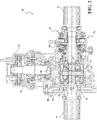
- a differential assembly 54 is illustrated in Figure 2 with first and second pinion gears 56, 58 fixed for rotation with a differential pin 60.
- Right and left side gears 62, 64 are in meshed engagement with the first and second pinion gears 56, 58.
- the right and left side gears 62, 64 are fixed for rotation with the respective right and left output shafts 42, 44 for transferring torque to the right and left rear wheels 14.
- the housing 52 of the differential assembly 54 is supported within the RDM 30 on multiple bearings 66.
- the housing 52 includes an outer differential housing 70 and an inner differential housing 72.
- the ring gear 50 is mounted to and fixed for rotation with the outer differential housing 70.
- the differential pin 60 is mounted to the inner differential housing 72.
- the inner differential housing 72 is fixed for rotation with the right output shaft 42.
- One or more bearings, such as needle bearings 74 may be position between the outer differential housing 70 and the inner differential housing 72.
- a disconnect and synch-lock mechanism 76 is actuated to selectively disconnect and synchronize and lock the outer and inner differential housings 70, 72.
- the disconnect and synch-lock mechanism 76 is mounted concentric with an output shaft of the differential assembly 54 on a side laterally opposite to the mounting of the ring gear 50.
- the disconnect and synch-lock mechanism 76 includes a synchronizing clutch or synch clutch 80 which is operable to synchronize and lock, or to disconnect, the outer and inner differential housings 70, 72.
- a clutch actuator 82 is operable to apply an axial force inwardly towards the differential assembly 54 in order to actuate the synch clutch 80.
- the synch clutch 80 may be multi-plate wet clutch and the same fluid may be used to lubricate the synch clutch 80 and other components of the RDM 30. Alternatively, the synch clutch 80 may be sealed and provided with a separate lubricant.
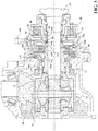
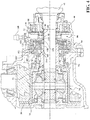
- the clutch actuator 82 includes an electromagnetically actuated pilot clutch 84 and a ball ramp mechanism 86 as shown in Figures 2 , 3 and 4 .
- the ball ramp mechanism 86 is fixed for rotation with the inner differential housing 72.
- the pilot clutch 84 consists of a coll assembly 88 which is adjacent a pilot clutch plate 90 and armature 92.
- the pilot clutch plate 90 is connected to the case 40 of the RDM 30 such as through a splined and grounded connection.
- Inner members (not shown) of the pilot clutch 84 are connected to a first cam plate 96 of the ball ramp mechanism 86.
- a second cam plate 98 is spaced apart from and faces the first cam plate 96.
- One or more grooves are defined in an inner face of each of the first and second cam plates 96, 98.
- An actuator ball 100 is positioned in the cavity defined by each pair of corresponding grooves. As shown in Figures 3 and 4 , in one embodiment, a first pair of grooves and an actuator ball 100 are positioned in the first and second cam plates 96, 98, above the right output shaft 42. A second pair of grooves and an actuator ball 100 are positioned in the first and second cam plates 96, 98, below the right output shaft 42.
- Each of the grooves may be ramped, tapered or shaped in a circumferential direction to configure the operation of the ball ramp mechanism 86 and the clutch actuator 82.
- the clutch actuator 82 includes an electromagnetically actuated pilot clutch 84 and a face cam mechanism (not shown).
- the face cam mechanism includes first and second cam plates with ramped or shaped surfaces configured to control axial movement of the second cam plate towards the synch clutch 80.
- the synch clutch 80 includes a drum 110 which Is fixed for rotation with the outer differential housing 70.
- a first set of plates 112 is connected to the drum 110 and a second set of plates 114 is connected to the inner differential housing 72.
- An end plate 116 is connected to the inner differential housing 72. The end plate 116 is adjacent the apply plate 102.
- the apply plate 102 is connected to and fixed for rotation with the inner differential housing 72.
- the apply plate 102 defines a cavity for receiving a spring 120 and a ball 122.
- the cavity faces outwardly, transverse to the longitudinal axis of the right output shaft 42.
- a first portion 124 of the second cam plate 98 also extends outwardly, transverse to the longitudinal axis of the right output shaft 42.
- a second portion 126 of the second cam plate 98 extends at an angle from the first portion 124 such that the second portion 126 of the second cam plate 98 extends towards and over the apply plate 102 to engage the ball 122.
- a bottom or inner surface of the second portion 126 of the cam plate 98 engages the ball 122 and defines at least one detent 130 for receiving the ball 122.
- Figure 3 shows the disconnect and synch-lock mechanism 76 and outer and inner differential housings 70, 72 in a synchronized and locked state with the ball ramp mechanism 86 closed.
- a spring 132 is disposed at an outer end of the inner differential housing 72 between the apply plate 102 and the second cam plate 98 in order to bias the ball ramp mechanism 86 in the closed position.
- Figure 4 shows the disconnect and synch-lock mechanism 76 and outer and inner differential housings 70, 72 in a disconnected state with the ball ramp mechanism 86 open.
- the outer and inner differential housings 70, 72 are connected together in one state via a splined connection between the drum 110 and the second portion 126 of the second cam plate 98.
- the second cam plate 98 also has a splined connection with inner differential housing 72 such that the outer and inner differential housings 70, 72 are locked and synchronized to rotate together.
- the coil assembly 88 is energized which pulls the armature 92 into the pilot clutch 84, causing the rotation of the first cam plate 96 to slow slightly relative to the rotation of the second cam plate 98.
- the actuator ball 100 moves within a first portion of the grooves configured in the first and second cam plates 96, 98, resulting in axial movement of the second cam plate 98 towards the differential assembly 54.
- the second cam plate 98 moves, the second portion 126 pushes on the ball 122 and spring 120 until the ball 122 is aligned with a first detent 130a in the second portion 96 of the cam plate 98.
- the synch clutch 80 and the splines between the second portion 126 of the cam plate 98 and the drum 110 are disengaged and this state remains once the coll assembly 88 is de-energized.
- the outer and inner differential housings 70, 72 are disconnected such that rotation of the inner differential housing 72 associated with the movement of the wheels 14 and rotation of the right output shaft 42 is not translated to the outer differential housing 70 and ring gear 50.
- the coil assembly 88 is energized again causing the rotation of the first cam plate 96 to slow slightly relative to the rotation of the second cam plate 98.
- the actuator ball 100 moves in a second portion of the grooves configured in the first and second cam 96, 98.
- the grooves in the first and second cam plates 96, 98 are configured such that the position of actuator ball 100 first causes a slight axial movement of the second cam plate 98 towards the differential assembly 54.
- a small force is applied by the second cam plate 98 on the apply plate 102 via the ball 122 and spring 120 in order to activate the synch clutch 80.
- the actuator ball 100 travels further in the third portion of the grooves configured in the first and second cam plates 96, 98.
- This third portion is configured with a sharp transition which causes a quick decrease in space between the first and second cam plates 96, 98 as the spring 132 forces axial movement of the second cam plate 98 away from the differential assembly 54 and towards the first cam plate 96.
- the outer and inner differential housings 70, 72 are again connected together via the splined connection between the drum 110 and the second portion 126 of the second cam plate 98 as shown in Figure 3 .
- the axial movement of the second cam plate 98 described during this transition also causes a change in position between the second portion 126 of the second cam plate 98 and the ball 122 and spring 120.
- the ball 122 rests in a second detent 130b defined in the second portion 126.
- the disconnect and synch-lock mechanism 76 and clutch actuator 82 have been described above with electromagnetic actuation through the coil assembly 88.
- the coil assembly 88 may be activated by a controller of the vehicle in response to data received from one or more sensors 140 in the vehicle. In this embodiment, no high power motor or high power controller is required, thus reducing the power required to operate the disconnect and synch-lock mechanism 76 and providing a better response for the synchronization of the outer and inner differential housings 70, 72.
- Such other mechanisms may include, but are not limited to, electro-mechanical actuation mechanisms or electro-hydraulic actuation mechanisms, such as a hydraulic piston.
- the apply plate 102 also may include a dog clutch to engage an end portion of either the outer or inner differential housing 70, 72,
Landscapes
- Engineering & Computer Science (AREA)
- General Engineering & Computer Science (AREA)
- Mechanical Engineering (AREA)
- Chemical & Material Sciences (AREA)
- Combustion & Propulsion (AREA)
- Transportation (AREA)
- Physics & Mathematics (AREA)
- Electromagnetism (AREA)
- Retarders (AREA)
- Mechanical Operated Clutches (AREA)
- Arrangement And Driving Of Transmission Devices (AREA)
Claims (9)
- Module d'entraînement arrière pour un assemblage de train d'entraînement (10) destiné à transférer un couple à des roues avant (12) et des roues arrière (14) d'un véhicule motorisé à quatre roues motrices comprenant :un assemblage de différentiel (54) ayant un boîtier de différentiel extérieur (70) et un boîtier de différentiel intérieur (72), le boîtier de différentiel intérieur (72) étant fixé pour une rotation avec un arbre de sortie (42) de l'assemblage de différentiel (54) ;un assemblage de couronne dentée ayant une couronne dentée (50) montée sur et fixée pour une rotation avec le boîtier de différentiel extérieur (70) ; etun mécanisme de déconnexion et de verrouillage de synchronisation (76) dont la fonction est de synchroniser et de verrouiller le boîtier de différentiel intérieur (72) et le boîtier de différentiel extérieur (70), et de déconnecter le boîtier de différentiel intérieur (72), par exemple quand un couple n'est pas en train d'être fourni depuis une transmission avant (16) du véhicule pour un entraînement des roues arrière (14) afin d'empêcher une rotation du boîtier de différentiel extérieur (70) et de la couronne dentée (50) et des pertes de chronométrage et de rapprochement paralytique qui y sont associées,le mécanisme de déconnexion et de verrouillage de synchronisation (76) comprenant un embrayage de synchronisation (80) et un actionneur d'embrayage (82), dans lequel l'embrayage de synchronisation (80) comprend un embrayage multidisque ayant un tambour (110) fixé pour une rotation avec le boîtier de différentiel extérieur (70), un premier jeu de disques connectés au tambour (110), et un second jeu de disques connectés au boîtier de différentiel intérieur (72) ;l'actionneur d'embrayage (82) a pour fonction de générer une force axiale dans une première direction vers l'assemblage de différentiel (54) pour activer l'embrayage de synchronisation (80), et l'actionneur d'embrayage (82) comprend un mécanisme de rampe à billes (86) ; etle mécanisme de rampe à billes (86) comprend un premier disque de came (96) définissant une première rainure, un second disque de came (98) définissant une seconde rainure faisant face à la première rainure, et au moins une bille d'actionneur (100) disposée entre le premier disque de came (96) et le second disque de came (98) dans la première et la seconde rainure, dans lequel une rotation relative du premier et du second disque de came (96, 98) amène une translation axiale du second disque de came (98) dans la première direction pour déplacement axial d'un disque d'application adjacent (102) pour activer l'embrayage de synchronisation (80),caractérisé en ce quele disque d'application (102) comprend un ressort (120) et une bille (122), et une première surface du second disque de came (98) définissant un ou plusieurs crans pour engager la bille (122) du disque d'application (102) .
- Module d'entraînement arrière selon la revendication 1, dans lequel le mécanisme de déconnexion et de verrouillage de synchronisation (76) comprend en outre un ressort (132) configuré pour solliciter le second disque de came (98) vers le premier disque de came (96).
- Module d'entraînement arrière selon la revendication 1, dans lequel, pour synchroniser et verrouiller le boîtier de différentiel intérieur (72) et le boîtier de différentiel extérieur (70), la première et la seconde rainure et ladite au moins une bille d'actionneur (100) sont configurées pour d'abord entraîner un déplacement axial du second disque de came (98) dans la première direction pour activer l'embrayage de synchronisation (80), et puis permettre un déplacement axial du second disque de came (98) dans une seconde direction, opposée à la première direction, pour connecter le second disque de came (98) et le tambour (110).
- Module d'entraînement arrière selon la revendication 3, dans lequel une portion extérieure du second disque de came (98) est configurée avec une connexion cannelée pour engager le tambour (110) de l'embrayage de synchronisation (80) quand le boîtier de différentiel intérieur (72) et le boîtier de différentiel extérieur (70) sont verrouillés.
- Module d'entraînement arrière selon la revendication 4, dans lequel, pour déconnecter le boîtier de différentiel intérieur (72) et le boîtier de différentiel extérieur (70), la première et la seconde rainure et ladite au moins une bille d'actionneur (100) sont configurées pour entraîner un déplacement axial du second disque de came (98) dans la première direction pour désengager le second disque de came (98) et le tambour (110) .
- Module d'entraînement arrière selon la revendication 1, dans lequel l'actionneur d'embrayage (82) comprend un mécanisme de came de face.
- Module d'entraînement arrière selon l'une quelconque des revendications 1 à 6, dans lequel la couronne dentée (50) et le mécanisme de déconnexion et de verrouillage de synchronisation (76) sont montés sur des côtés latéraux opposés de l'assemblage de différentiel (54).
- Module d'entraînement arrière selon l'une quelconque des revendications 1 à 7, dans lequel l'assemblage de couronne dentée comprend un assemblage de couronne dentée en porte-à-faux.
- Module d'entraînement arrière selon l'une quelconque des revendications 1 à 8, dans lequel l'actionneur d'embrayage (82) est actionné par électromagnétisme.
Applications Claiming Priority (2)
| Application Number | Priority Date | Filing Date | Title |
|---|---|---|---|
| US201562254279P | 2015-11-12 | 2015-11-12 | |
| PCT/US2016/061831 WO2017083821A1 (fr) | 2015-11-12 | 2016-11-14 | Module de propulsion arrière ayant un mécanisme de découplage de couronne et de verrouillage de synchronisation |
Publications (2)
| Publication Number | Publication Date |
|---|---|
| EP3374668A1 EP3374668A1 (fr) | 2018-09-19 |
| EP3374668B1 true EP3374668B1 (fr) | 2021-09-22 |
Family
ID=57543152
Family Applications (1)
| Application Number | Title | Priority Date | Filing Date |
|---|---|---|---|
| EP16810133.5A Active EP3374668B1 (fr) | 2015-11-12 | 2016-11-14 | Module de propulsion arrière ayant un mécanisme de découplage de couronne et de verrouillage de synchronisation |
Country Status (4)
| Country | Link |
|---|---|
| US (1) | US11142066B2 (fr) |
| EP (1) | EP3374668B1 (fr) |
| JP (1) | JP6926103B2 (fr) |
| WO (1) | WO2017083821A1 (fr) |
Families Citing this family (8)
| Publication number | Priority date | Publication date | Assignee | Title |
|---|---|---|---|---|
| GB2545461B (en) * | 2015-12-17 | 2020-11-18 | Countytrac Ltd | Compact vehicle drive train |
| US10724622B2 (en) | 2016-10-27 | 2020-07-28 | Team Industries, Inc. | Narrow packaging locking differential |
| ES2986352T3 (es) | 2018-04-26 | 2024-11-11 | Team Ind Inc | Diferencial de bloqueo |
| US11739838B2 (en) | 2021-06-02 | 2023-08-29 | Dana Graziano S.R.L. | Park lock with dog clutch and ball ramp |
| US11892065B2 (en) | 2021-08-17 | 2024-02-06 | Means Industries, Inc. | Drivetrain component |
| DE102022202312A1 (de) | 2022-03-08 | 2023-09-14 | Zf Friedrichshafen Ag | Getriebevorrichtung für ein Kraftfahrzeug |
| US12422032B2 (en) * | 2023-06-14 | 2025-09-23 | Schaeffler Technologies AG & Co. KG | Electronic differential disconnect clutch |
| KR20260019911A (ko) * | 2024-08-02 | 2026-02-10 | 현대트랜시스 주식회사 | 차동제한 장치를 구비하는 디스커넥터 장치 |
Family Cites Families (13)
| Publication number | Priority date | Publication date | Assignee | Title |
|---|---|---|---|---|
| JPS61112844A (ja) * | 1984-11-05 | 1986-05-30 | Toyota Motor Corp | ドライブシヤフトの断続機構を備えた4輪駆動車 |
| US4781078A (en) * | 1987-02-02 | 1988-11-01 | Dana Corporation | Locking differential with electromagnetic actuated clutch |
| JP4778648B2 (ja) * | 2001-09-14 | 2011-09-21 | Gknドライブラインジャパン株式会社 | 電動モータ用動力伝達装置及びその組み付け方法 |
| DE102005041080A1 (de) * | 2004-08-31 | 2006-03-16 | Tochigi Fuji Sangyo K.K. | Reibeingriffsvorrichtung |
| JP2006071071A (ja) * | 2004-09-06 | 2006-03-16 | Gkn ドライブライン トルクテクノロジー株式会社 | デファレンシャル装置 |
| US20070095628A1 (en) * | 2005-10-28 | 2007-05-03 | Magna Powertrain Usa, Inc. | Power-operated clutch actuator for torque transfer mechanisms |
| US8308598B2 (en) * | 2007-09-13 | 2012-11-13 | Borgwarner, Inc. | Controlled differential actuator |
| EP2131155A1 (fr) | 2008-06-04 | 2009-12-09 | ads-tec GmbH | Procédé de détermination de données de consommation d'énergie d'un dispositif avec des utilisateurs et armoire d'alimentation destinée à la détermination de données de consommation d'énergie |
| DE102008037885B4 (de) | 2008-08-15 | 2020-08-06 | Gkn Automotive Limited | Kupplungsanordnung und Antriebsstranganordnung für ein mehrachsgetriebenes Kraftfahrzeug |
| CA2677392C (fr) * | 2008-09-09 | 2016-11-29 | Magna Powertrain Usa, Inc. | Unite de prise de force avec couplage actif et systeme de deconnexion hypoide |
| US8436854B2 (en) | 2009-05-29 | 2013-05-07 | Qualcomm Incorporated | Graphics processing unit with deferred vertex shading |
| US8469854B1 (en) * | 2012-05-15 | 2013-06-25 | American Axle & Manufacturing, Inc. | Disconnectable driveline for all-wheel drive vehicle |
| US9701195B2 (en) * | 2013-06-14 | 2017-07-11 | Dana Automotive Systems Group, Llc | Differential with torque coupling |
-
2016
- 2016-11-14 WO PCT/US2016/061831 patent/WO2017083821A1/fr not_active Ceased
- 2016-11-14 US US15/775,975 patent/US11142066B2/en active Active
- 2016-11-14 JP JP2018545103A patent/JP6926103B2/ja not_active Expired - Fee Related
- 2016-11-14 EP EP16810133.5A patent/EP3374668B1/fr active Active
Also Published As
| Publication number | Publication date |
|---|---|
| US20180326844A1 (en) | 2018-11-15 |
| EP3374668A1 (fr) | 2018-09-19 |
| CA3005258A1 (fr) | 2017-05-18 |
| US11142066B2 (en) | 2021-10-12 |
| JP6926103B2 (ja) | 2021-08-25 |
| WO2017083821A1 (fr) | 2017-05-18 |
| JP2018534510A (ja) | 2018-11-22 |
Similar Documents
| Publication | Publication Date | Title |
|---|---|---|
| US11142066B2 (en) | Rear drive module having a ring gear disconnect and synch-lock mechanism | |
| KR101759463B1 (ko) | 능동 건식 단절 시스템을 구비한 전륜 구동 | |
| US11168743B2 (en) | Shift isolation lever system for power-actuated coupling device | |
| KR101633143B1 (ko) | 연결해제 시스템을 갖는 awd 차량 | |
| US8597150B1 (en) | Disconnectable driveline for all-wheel drive vehicle | |
| US9302581B1 (en) | All-wheel drive driveline with disconnecting axle | |
| CN102202927B (zh) | 用于多轴传动机动车的联接组件和驱动系组件 | |
| US8388486B2 (en) | AWD vehicle with active disconnect coupling having multi-stage ball ramp | |
| US8308598B2 (en) | Controlled differential actuator | |
| JP2004308907A (ja) | ボール・ランプ式アクチュエータ機構を備えたシンクロ装置 | |
| US11365770B2 (en) | Self-energizing electromagnetic disconnect actuator | |
| US11859696B2 (en) | Module for a system for synchronizing and driving a transmission gearbox countershaft | |
| MX2011003419A (es) | Desconexion de rueda de modulo de traccion trasera. | |
| CA3005258C (fr) | Module de propulsion arriere ayant un mecanisme de decouplage de couronne et de verrouillage de synchronisation | |
| CN107848413B (zh) | 由同步事件提供动力的传动系统致动器 | |
| JP2014148267A (ja) | 四輪駆動車両 | |
| US20170246953A1 (en) | An awd transverse powertrain with rear wheel bias field |
Legal Events
| Date | Code | Title | Description |
|---|---|---|---|
| STAA | Information on the status of an ep patent application or granted ep patent |
Free format text: STATUS: UNKNOWN |
|
| STAA | Information on the status of an ep patent application or granted ep patent |
Free format text: STATUS: THE INTERNATIONAL PUBLICATION HAS BEEN MADE |
|
| PUAI | Public reference made under article 153(3) epc to a published international application that has entered the european phase |
Free format text: ORIGINAL CODE: 0009012 |
|
| STAA | Information on the status of an ep patent application or granted ep patent |
Free format text: STATUS: REQUEST FOR EXAMINATION WAS MADE |
|
| 17P | Request for examination filed |
Effective date: 20180523 |
|
| AK | Designated contracting states |
Kind code of ref document: A1 Designated state(s): AL AT BE BG CH CY CZ DE DK EE ES FI FR GB GR HR HU IE IS IT LI LT LU LV MC MK MT NL NO PL PT RO RS SE SI SK SM TR |
|
| AX | Request for extension of the european patent |
Extension state: BA ME |
|
| DAV | Request for validation of the european patent (deleted) | ||
| DAX | Request for extension of the european patent (deleted) | ||
| STAA | Information on the status of an ep patent application or granted ep patent |
Free format text: STATUS: EXAMINATION IS IN PROGRESS |
|
| 17Q | First examination report despatched |
Effective date: 20200102 |
|
| GRAP | Despatch of communication of intention to grant a patent |
Free format text: ORIGINAL CODE: EPIDOSNIGR1 |
|
| STAA | Information on the status of an ep patent application or granted ep patent |
Free format text: STATUS: GRANT OF PATENT IS INTENDED |
|
| INTG | Intention to grant announced |
Effective date: 20210422 |
|
| GRAS | Grant fee paid |
Free format text: ORIGINAL CODE: EPIDOSNIGR3 |
|
| GRAA | (expected) grant |
Free format text: ORIGINAL CODE: 0009210 |
|
| STAA | Information on the status of an ep patent application or granted ep patent |
Free format text: STATUS: THE PATENT HAS BEEN GRANTED |
|
| AK | Designated contracting states |
Kind code of ref document: B1 Designated state(s): AL AT BE BG CH CY CZ DE DK EE ES FI FR GB GR HR HU IE IS IT LI LT LU LV MC MK MT NL NO PL PT RO RS SE SI SK SM TR |
|
| REG | Reference to a national code |
Ref country code: GB Ref legal event code: FG4D |
|
| REG | Reference to a national code |
Ref country code: IE Ref legal event code: FG4D |
|
| REG | Reference to a national code |
Ref country code: DE Ref legal event code: R096 Ref document number: 602016064086 Country of ref document: DE |
|
| REG | Reference to a national code |
Ref country code: CH Ref legal event code: EP Ref country code: AT Ref legal event code: REF Ref document number: 1432578 Country of ref document: AT Kind code of ref document: T Effective date: 20211015 |
|
| REG | Reference to a national code |
Ref country code: LT Ref legal event code: MG9D |
|
| REG | Reference to a national code |
Ref country code: NL Ref legal event code: MP Effective date: 20210922 |
|
| PG25 | Lapsed in a contracting state [announced via postgrant information from national office to epo] |
Ref country code: FI Free format text: LAPSE BECAUSE OF FAILURE TO SUBMIT A TRANSLATION OF THE DESCRIPTION OR TO PAY THE FEE WITHIN THE PRESCRIBED TIME-LIMIT Effective date: 20210922 Ref country code: HR Free format text: LAPSE BECAUSE OF FAILURE TO SUBMIT A TRANSLATION OF THE DESCRIPTION OR TO PAY THE FEE WITHIN THE PRESCRIBED TIME-LIMIT Effective date: 20210922 Ref country code: NO Free format text: LAPSE BECAUSE OF FAILURE TO SUBMIT A TRANSLATION OF THE DESCRIPTION OR TO PAY THE FEE WITHIN THE PRESCRIBED TIME-LIMIT Effective date: 20211222 Ref country code: LT Free format text: LAPSE BECAUSE OF FAILURE TO SUBMIT A TRANSLATION OF THE DESCRIPTION OR TO PAY THE FEE WITHIN THE PRESCRIBED TIME-LIMIT Effective date: 20210922 Ref country code: BG Free format text: LAPSE BECAUSE OF FAILURE TO SUBMIT A TRANSLATION OF THE DESCRIPTION OR TO PAY THE FEE WITHIN THE PRESCRIBED TIME-LIMIT Effective date: 20211222 Ref country code: RS Free format text: LAPSE BECAUSE OF FAILURE TO SUBMIT A TRANSLATION OF THE DESCRIPTION OR TO PAY THE FEE WITHIN THE PRESCRIBED TIME-LIMIT Effective date: 20210922 Ref country code: SE Free format text: LAPSE BECAUSE OF FAILURE TO SUBMIT A TRANSLATION OF THE DESCRIPTION OR TO PAY THE FEE WITHIN THE PRESCRIBED TIME-LIMIT Effective date: 20210922 |
|
| REG | Reference to a national code |
Ref country code: AT Ref legal event code: MK05 Ref document number: 1432578 Country of ref document: AT Kind code of ref document: T Effective date: 20210922 |
|
| PG25 | Lapsed in a contracting state [announced via postgrant information from national office to epo] |
Ref country code: LV Free format text: LAPSE BECAUSE OF FAILURE TO SUBMIT A TRANSLATION OF THE DESCRIPTION OR TO PAY THE FEE WITHIN THE PRESCRIBED TIME-LIMIT Effective date: 20210922 Ref country code: GR Free format text: LAPSE BECAUSE OF FAILURE TO SUBMIT A TRANSLATION OF THE DESCRIPTION OR TO PAY THE FEE WITHIN THE PRESCRIBED TIME-LIMIT Effective date: 20211223 |
|
| PG25 | Lapsed in a contracting state [announced via postgrant information from national office to epo] |
Ref country code: AT Free format text: LAPSE BECAUSE OF FAILURE TO SUBMIT A TRANSLATION OF THE DESCRIPTION OR TO PAY THE FEE WITHIN THE PRESCRIBED TIME-LIMIT Effective date: 20210922 |
|
| PG25 | Lapsed in a contracting state [announced via postgrant information from national office to epo] |
Ref country code: IS Free format text: LAPSE BECAUSE OF FAILURE TO SUBMIT A TRANSLATION OF THE DESCRIPTION OR TO PAY THE FEE WITHIN THE PRESCRIBED TIME-LIMIT Effective date: 20220122 Ref country code: SK Free format text: LAPSE BECAUSE OF FAILURE TO SUBMIT A TRANSLATION OF THE DESCRIPTION OR TO PAY THE FEE WITHIN THE PRESCRIBED TIME-LIMIT Effective date: 20210922 Ref country code: RO Free format text: LAPSE BECAUSE OF FAILURE TO SUBMIT A TRANSLATION OF THE DESCRIPTION OR TO PAY THE FEE WITHIN THE PRESCRIBED TIME-LIMIT Effective date: 20210922 Ref country code: PT Free format text: LAPSE BECAUSE OF FAILURE TO SUBMIT A TRANSLATION OF THE DESCRIPTION OR TO PAY THE FEE WITHIN THE PRESCRIBED TIME-LIMIT Effective date: 20220124 Ref country code: PL Free format text: LAPSE BECAUSE OF FAILURE TO SUBMIT A TRANSLATION OF THE DESCRIPTION OR TO PAY THE FEE WITHIN THE PRESCRIBED TIME-LIMIT Effective date: 20210922 Ref country code: NL Free format text: LAPSE BECAUSE OF FAILURE TO SUBMIT A TRANSLATION OF THE DESCRIPTION OR TO PAY THE FEE WITHIN THE PRESCRIBED TIME-LIMIT Effective date: 20210922 Ref country code: ES Free format text: LAPSE BECAUSE OF FAILURE TO SUBMIT A TRANSLATION OF THE DESCRIPTION OR TO PAY THE FEE WITHIN THE PRESCRIBED TIME-LIMIT Effective date: 20210922 Ref country code: EE Free format text: LAPSE BECAUSE OF FAILURE TO SUBMIT A TRANSLATION OF THE DESCRIPTION OR TO PAY THE FEE WITHIN THE PRESCRIBED TIME-LIMIT Effective date: 20210922 Ref country code: CZ Free format text: LAPSE BECAUSE OF FAILURE TO SUBMIT A TRANSLATION OF THE DESCRIPTION OR TO PAY THE FEE WITHIN THE PRESCRIBED TIME-LIMIT Effective date: 20210922 Ref country code: AL Free format text: LAPSE BECAUSE OF FAILURE TO SUBMIT A TRANSLATION OF THE DESCRIPTION OR TO PAY THE FEE WITHIN THE PRESCRIBED TIME-LIMIT Effective date: 20210922 |
|
| REG | Reference to a national code |
Ref country code: DE Ref legal event code: R097 Ref document number: 602016064086 Country of ref document: DE |
|
| PG25 | Lapsed in a contracting state [announced via postgrant information from national office to epo] |
Ref country code: MC Free format text: LAPSE BECAUSE OF FAILURE TO SUBMIT A TRANSLATION OF THE DESCRIPTION OR TO PAY THE FEE WITHIN THE PRESCRIBED TIME-LIMIT Effective date: 20210922 |
|
| REG | Reference to a national code |
Ref country code: CH Ref legal event code: PL |
|
| PG25 | Lapsed in a contracting state [announced via postgrant information from national office to epo] |
Ref country code: LU Free format text: LAPSE BECAUSE OF NON-PAYMENT OF DUE FEES Effective date: 20211114 Ref country code: DK Free format text: LAPSE BECAUSE OF FAILURE TO SUBMIT A TRANSLATION OF THE DESCRIPTION OR TO PAY THE FEE WITHIN THE PRESCRIBED TIME-LIMIT Effective date: 20210922 Ref country code: BE Free format text: LAPSE BECAUSE OF NON-PAYMENT OF DUE FEES Effective date: 20211130 |
|
| PLBE | No opposition filed within time limit |
Free format text: ORIGINAL CODE: 0009261 |
|
| STAA | Information on the status of an ep patent application or granted ep patent |
Free format text: STATUS: NO OPPOSITION FILED WITHIN TIME LIMIT |
|
| REG | Reference to a national code |
Ref country code: BE Ref legal event code: MM Effective date: 20211130 |
|
| 26N | No opposition filed |
Effective date: 20220623 |
|
| PG25 | Lapsed in a contracting state [announced via postgrant information from national office to epo] |
Ref country code: IE Free format text: LAPSE BECAUSE OF NON-PAYMENT OF DUE FEES Effective date: 20211114 |
|
| PG25 | Lapsed in a contracting state [announced via postgrant information from national office to epo] |
Ref country code: SI Free format text: LAPSE BECAUSE OF FAILURE TO SUBMIT A TRANSLATION OF THE DESCRIPTION OR TO PAY THE FEE WITHIN THE PRESCRIBED TIME-LIMIT Effective date: 20210922 Ref country code: FR Free format text: LAPSE BECAUSE OF NON-PAYMENT OF DUE FEES Effective date: 20211122 |
|
| PG25 | Lapsed in a contracting state [announced via postgrant information from national office to epo] |
Ref country code: IT Free format text: LAPSE BECAUSE OF FAILURE TO SUBMIT A TRANSLATION OF THE DESCRIPTION OR TO PAY THE FEE WITHIN THE PRESCRIBED TIME-LIMIT Effective date: 20210922 |
|
| PG25 | Lapsed in a contracting state [announced via postgrant information from national office to epo] |
Ref country code: HU Free format text: LAPSE BECAUSE OF FAILURE TO SUBMIT A TRANSLATION OF THE DESCRIPTION OR TO PAY THE FEE WITHIN THE PRESCRIBED TIME-LIMIT; INVALID AB INITIO Effective date: 20161114 |
|
| PG25 | Lapsed in a contracting state [announced via postgrant information from national office to epo] |
Ref country code: CY Free format text: LAPSE BECAUSE OF FAILURE TO SUBMIT A TRANSLATION OF THE DESCRIPTION OR TO PAY THE FEE WITHIN THE PRESCRIBED TIME-LIMIT Effective date: 20210922 |
|
| PG25 | Lapsed in a contracting state [announced via postgrant information from national office to epo] |
Ref country code: SM Free format text: LAPSE BECAUSE OF FAILURE TO SUBMIT A TRANSLATION OF THE DESCRIPTION OR TO PAY THE FEE WITHIN THE PRESCRIBED TIME-LIMIT Effective date: 20210922 Ref country code: LI Free format text: LAPSE BECAUSE OF NON-PAYMENT OF DUE FEES Effective date: 20220701 Ref country code: CH Free format text: LAPSE BECAUSE OF NON-PAYMENT OF DUE FEES Effective date: 20220701 |
|
| PG25 | Lapsed in a contracting state [announced via postgrant information from national office to epo] |
Ref country code: MK Free format text: LAPSE BECAUSE OF FAILURE TO SUBMIT A TRANSLATION OF THE DESCRIPTION OR TO PAY THE FEE WITHIN THE PRESCRIBED TIME-LIMIT Effective date: 20210922 |
|
| PG25 | Lapsed in a contracting state [announced via postgrant information from national office to epo] |
Ref country code: MT Free format text: LAPSE BECAUSE OF FAILURE TO SUBMIT A TRANSLATION OF THE DESCRIPTION OR TO PAY THE FEE WITHIN THE PRESCRIBED TIME-LIMIT Effective date: 20210922 |
|
| REG | Reference to a national code |
Ref country code: DE Ref legal event code: R082 Ref document number: 602016064086 Country of ref document: DE Representative=s name: WITTE, WELLER & PARTNER PATENTANWAELTE MBB, DE |
|
| PG25 | Lapsed in a contracting state [announced via postgrant information from national office to epo] |
Ref country code: TR Free format text: LAPSE BECAUSE OF FAILURE TO SUBMIT A TRANSLATION OF THE DESCRIPTION OR TO PAY THE FEE WITHIN THE PRESCRIBED TIME-LIMIT Effective date: 20210922 |
|
| PGFP | Annual fee paid to national office [announced via postgrant information from national office to epo] |
Ref country code: DE Payment date: 20251126 Year of fee payment: 10 |
|
| PGFP | Annual fee paid to national office [announced via postgrant information from national office to epo] |
Ref country code: GB Payment date: 20251121 Year of fee payment: 10 |