EP3374761B1 - Support pour caméra - Google Patents
Support pour caméra Download PDFInfo
- Publication number
- EP3374761B1 EP3374761B1 EP15908026.6A EP15908026A EP3374761B1 EP 3374761 B1 EP3374761 B1 EP 3374761B1 EP 15908026 A EP15908026 A EP 15908026A EP 3374761 B1 EP3374761 B1 EP 3374761B1
- Authority
- EP
- European Patent Office
- Prior art keywords
- skid
- camera
- front portion
- grooves
- pipe
- Prior art date
- Legal status (The legal status is an assumption and is not a legal conclusion. Google has not performed a legal analysis and makes no representation as to the accuracy of the status listed.)
- Active
Links
Images



Classifications
-
- G—PHYSICS
- G02—OPTICS
- G02B—OPTICAL ELEMENTS, SYSTEMS OR APPARATUS
- G02B23/00—Telescopes, e.g. binoculars; Periscopes; Instruments for viewing the inside of hollow bodies; Viewfinders; Optical aiming or sighting devices
- G02B23/24—Instruments or systems for viewing the inside of hollow bodies, e.g. fibrescopes
- G02B23/2476—Non-optical details, e.g. housings, mountings, supports
- G02B23/2484—Arrangements in relation to a camera or imaging device
-
- G—PHYSICS
- G01—MEASURING; TESTING
- G01N—INVESTIGATING OR ANALYSING MATERIALS BY DETERMINING THEIR CHEMICAL OR PHYSICAL PROPERTIES
- G01N21/00—Investigating or analysing materials by the use of optical means, i.e. using sub-millimetre waves, infrared, visible or ultraviolet light
- G01N21/84—Systems specially adapted for particular applications
- G01N21/88—Investigating the presence of flaws or contamination
- G01N21/95—Investigating the presence of flaws or contamination characterised by the material or shape of the object to be examined
- G01N21/954—Inspecting the inner surface of hollow bodies, e.g. bores
-
- G—PHYSICS
- G02—OPTICS
- G02B—OPTICAL ELEMENTS, SYSTEMS OR APPARATUS
- G02B23/00—Telescopes, e.g. binoculars; Periscopes; Instruments for viewing the inside of hollow bodies; Viewfinders; Optical aiming or sighting devices
- G02B23/24—Instruments or systems for viewing the inside of hollow bodies, e.g. fibrescopes
- G02B23/2476—Non-optical details, e.g. housings, mountings, supports
-
- G—PHYSICS
- G02—OPTICS
- G02B—OPTICAL ELEMENTS, SYSTEMS OR APPARATUS
- G02B23/00—Telescopes, e.g. binoculars; Periscopes; Instruments for viewing the inside of hollow bodies; Viewfinders; Optical aiming or sighting devices
- G02B23/24—Instruments or systems for viewing the inside of hollow bodies, e.g. fibrescopes
- G02B23/2476—Non-optical details, e.g. housings, mountings, supports
- G02B23/2492—Arrangements for use in a hostile environment, e.g. a very hot, cold or radioactive environment
-
- H—ELECTRICITY
- H04—ELECTRIC COMMUNICATION TECHNIQUE
- H04N—PICTORIAL COMMUNICATION, e.g. TELEVISION
- H04N23/00—Cameras or camera modules comprising electronic image sensors; Control thereof
- H04N23/50—Constructional details
- H04N23/51—Housings
Definitions
- the present disclosure relates to a camera skid and to a method for inspecting a pipe.
- Underground pipes are often inspected with the use of cameras.
- the cameras are typically inserted into the pipe and are propelled down the pipe using the cabling to the camera. As such, the camera is propelled into a rough environment and often uses skid devices for protection and alignment.
- the camera skid holds the camera and provides alignment and protection for the camera as it is inserted into the pipe for inspection.
- JP2010102244 is a document that discusses an in-pipe inspection camera device having work efficiency and such a structure of engaging the sliding part of a reliable camera head.
- US8540429 is a document that describes a pipe guide which includes: a pair of cylindrical shells with radially extending circumferentially spaced vanes; a pair of curved tab arms; and a pair of slide-locks.
- US8289385 describes a push-cable comprising a central core including a least one conductor, a plurality of non-metallic resilient flexible stiffness members surrounding the core, and a layer of sheathing surrounding the stiffness members.
- US2004/083829 is a guide for a video pipe inspection system that includes a camera head and a tubular coil spring having a central axis.
- US5571977 described a process for inspecting subsidiary canals that branch off from a main drain.
- a camera skid as defined in claim 1, and a method for inspecting a pipe using the skid, are presented.
- the camera skid includes a body into which a camera can be inserted wherein the body is constructed of a first material wherein the first material is a rigid or semi-rigid material; and a front portion received into the body, the front portion including a lip that contacts a face of the camera, wherein the front portion (102) is constructed of a pliable material less rigid than the first material and wherein the area of the front face of the camera remains partially exposed by the front portion when the camera is in the skid.
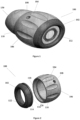
- Figure 1 illustrates a camera skid 100 according to some embodiments of the present invention.
- Camera skid 100 includes body 104 and a front portion 102.
- a camera 112 can be positioned through body 104 and rests on front portion 102 such that front portion 102 extends beyond the front face of camera 112.
- Figure 1 illustrates a cable boot 130 contacting with body 104 of camera skid 100.
- Skid body 104 also includes set holes 108 that allows set screws (now shown) to contact camera 112 and rigidly hold camera 112 in place.
- Skid body 104 also includes ridges 110 and grooves 106 between the ridges. Ridges 110 help guide skid 100 through the pipe while grooves 106 help direct fluid in the pipe around skid 100.
- camera skid 100 provides protection for the face of camera 112 from offsets or debris in a pipe through which camera skid 100 is directed. Further, camera skid 100 can help center camera 112 in the pipe while keeping camera 112 off the pipe itself. By keeping camera 112 off the floor of the pipe, the spread of light provided by camera 112 can be improved, resulting in better imaging of the interior of the pipe.
- FIG. 2 illustrates the separated portions of skid 100, the front portion 102 and the body 104 are separated.
- front portion 102 includes a lip 122 that overhangs the face of camera 112.
- Front portion 102 also includes a lip 116 and groove 114 that mates with a corresponding groove 118 and lip 120 on the interior of skid body 104 that receives front portion 102.
- Body 104 and front portion 102 are sized to receive camera 112 such that the front face of camera 112 is positioned in front portion 120 and in contact with lip 122.
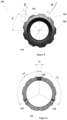
- FIG 3 illustrates a side view of skid 100.
- skid 100 has a length L1.
- Body 104 has a rear outer diameter 02, the rear of skid 100 being opposite front portion 102, and an outer diameter 01 across ribs 110 at their maximum diameter.
- the outer diameter of front portion 102 is 03.
- Figure 4 illustrates a cross-sectional view of skid 100 onto the plane defined by A-A illustrated in Figure 3 .
- set screw hole 108 is formed in a ridge 110.
- Set screw hole 108 is located a distance L2 from the rear of skid 100.
- the inner diameter of the rear of skid 100 is 04.
- the innermost diameter of front portion 102 is given by 05.
- the outer diameter of groove 114 of front portion 102 is given by 06, which is also the inner diameter of body 104 at lip 118.
- the diameter of lip 116 of front portion 102 is given by diameter 07, which is also the inner diameter of groove 120 of body 104.
- Figure 5 illustrates a cross-sectional view of body 104 of skid 100 through the plane indicated by B-B in Figure 3 .
- the cross-sectional diameter between a groove 106 and a ridge 110 is given by 08.
- grooves 106 can be defined by a circle with diameter 09. Additionally, the centers of grooves 106 are separated by an angle A1 from the center of body 104.
- Figure 6 illustrates a cross-section view of body 104 of skid 100 through the plane indicated by C-C in Figure 4 .
- This plane passes cross-sectionally through screw holes 108.
- screw holes 108 are positioned around body 104 and are separated by angles A2 and A3. Although there may be any number of screw holes 108 for holding set screws (not shown), Figure 6 illustrates an embodiment with three screw holes 108. As is further illustrated in Figure 6 , screw holes 108 are tapped to accommodate a set screw of type S1.
- Skid 100 can be sized to accommodate any inspection camera.
- the dimensions for an example skid 100 that can accommodate a 25mm camera, a 34 mm camera, and a 45 mm are provided in Table I.
- Other sized cameras can be accommodated by adjusting the dimensions to fit the particular camera being used.
- cameras having different shapes can be used with particular camera sizes. Consequently, the dimensions provided in Table I are examples only and are not intended to be limiting.
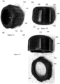
- Figures 7A through 7E illustrates various perspectives of a skid 100 as illustrated above.
- the Embodiment of skid 100 illustrates in Figures 7A through 7E include guide protrusions 704 formed in body 104 and complementary receptors 706 formed in front portion 102.
- Such protrusions 704 and receptors 706 allow front portion 102 to be positioned onto body 104 in a limited number of angular orientations, depending on the number of protrusion 704 and receptor 706 pairs.
- protrusions 704 may be formed in front portion 102 while receptors 706 may be formed in body 104.
- FIGs 8A through 8E illustrate various perspectives of another example of skid 100 as discussed above.
- the example of skid 100 shown in Figures 8A through 8E includes an elongated body portion 802 along with a rear curved portion 804 and front curved portion 806.
- Elongated body portion 802 is a flat portion of body 104 that extends between curved portions 804 and 806.
- Front portion 102 attaches to front curved portion 806 while hole sets 108 are formed in curved portion 804.
- Figures 9A through 9E illustrates various perspectives of another example of skid 100 as discussed above.
- the example of skid 100 shown in Figures 9A through 9E have grooves 106 that are flat bottomed instead of circularly shaped, as is illustrated in Figure 5 .
- body 104 is tapered instead of rounded or flat such that front portion 102 is inserted into the side with the greatest diameter.
- body 104 is constructed of a rigid material such as, for example, hard plastic, aluminum, steel, rubber, or other rigid or semi-rigid material.
- Front portion 102 is, according to the invention, constructed of a pliable material such as rubber.
- skid 100 can be formed in a number of different shapes and configurations that house a camera and allow camera inspections of various pipes.
Landscapes
- Physics & Mathematics (AREA)
- General Physics & Mathematics (AREA)
- Optics & Photonics (AREA)
- Astronomy & Astrophysics (AREA)
- Analytical Chemistry (AREA)
- Multimedia (AREA)
- General Health & Medical Sciences (AREA)
- Chemical & Material Sciences (AREA)
- Immunology (AREA)
- Pathology (AREA)
- Engineering & Computer Science (AREA)
- Biochemistry (AREA)
- Life Sciences & Earth Sciences (AREA)
- Health & Medical Sciences (AREA)
- Signal Processing (AREA)
- Studio Devices (AREA)
- Accessories Of Cameras (AREA)
- Investigating Materials By The Use Of Optical Means Adapted For Particular Applications (AREA)
Claims (15)
- Support de caméra, comprenant :un corps (104) dans lequel peut être insérée une caméra (112), dans lequel le corps (104) est constitué d'un premier matériau, le premier matériau étant un matériau rigide ou semi-rigide ; etune partie avant (102) reçue dans le corps (104), la partie avant (102) comprenant une lèvre (122) qui entre en contact avec une face avant de la caméra (112) lorsque la caméra (112) est insérée dans le corps (104),caractérisé en ce que la partie avant (102) est constituée d'un matériau souple moins rigide que le premier matériau.
- Support selon la revendication 1, dans lequel la partie avant (102) comprend une rainure (114) et une lèvre (116) qui s'accouple avec une lèvre de corps (120) et une rainure de corps (118) formées dans le corps (104).
- Support selon la revendication 1, dans lequel le corps (104) comporte des trous de vis de réglage (108) qui accueillent des vis de réglage pour fixer la caméra (112) en place.
- Support selon la revendication 3, dans lequel les trous de vis de réglage (108) sont positionnés à des distances angulaires égales autour du corps (104).
- Support selon la revendication 1, dans lequel le corps (104) comporte des arêtes (110) et des rainures (106) autour d'une partie externe du corps (104), les rainures (106) s'étendant entre les arêtes (110), chaque rainure (106) et chaque arête (110) s'étendant dans une direction allant d'une première extrémité du corps (104) à une seconde extrémité du corps (104), la première extrémité étant adjacente à la partie avant, la seconde extrémité étant opposée à l'extrémité avant, les rainures s'étendant à travers une partie la plus large du support de caméra pour aider à guider un fluide dans un tuyau autour du support de caméra.
- Support selon la revendication 5, dans lequel les rainures (106) sont de forme circulaire.
- Support selon la revendication 5, dans lequel les rainures (106) sont à fond plat.
- Support selon la revendication 1, dans lequel un diamètre externe à l'arrière du corps (104) est inférieur à un diamètre externe au centre du corps (104).
- Support selon la revendication 1, dans lequel un diamètre externe au centre du corps (104) est une constante entre deux bords arrondis.
- Support selon la revendication 1, dans lequel le corps (104) est effilé.
- Support selon la revendication 1, dans lequel le corps (104) comporte des saillies (704) et la partie avant comporte des récepteurs (706) destinés à recevoir les saillies (704).
- Support selon la revendication 1, dans lequel la partie avant comporte des saillies et le corps (104) comporte des récepteurs destinés à recevoir les saillies.
- Procédé d'inspection d'un tuyau, le procédé comprenant :l'obtention d'un ensemble comprenant une caméra d'inspection (112) et un support de caméra (100), la caméra (112) ayant été insérée dans un corps (104) du support (100) dans lequel le corps (104) est constitué d'un premier matériau, le premier matériau étant un matériau rigide ou semi-rigide ;l'imagerie d'un intérieur du tuyau avec l'ensemble, l'imagerie comprenant :l'insertion de l'ensemble dans le tuyau ; etla propulsion de l'ensemble dans le tuyau ;dans lequel le support comprend une partie avant (102) reçue dans le corps (104), la partie avant (102) comprenant une lèvre (122) qui entre en contact avec une face avant de la caméra (112), caractérisé en ce que la partie avant (102) est constituée d'un matériau souple moins rigide que le premier matériau.
- Procédé selon la revendication 13, dans lequel le corps (104) comprend des arêtes (110) et des rainures (106) autour d'une partie externe du corps (104), les rainures (106) s'étendant entre les crêtes (110), chaque rainure (106) et chaque arête (110) s'étendant dans une direction allant d'une première extrémité du corps (104) à une seconde extrémité du corps (104), la première extrémité étant adjacente à la partie avant, la seconde extrémité étant opposée à l'extrémité avant, les rainures s'étendant à travers une partie la plus large du support de caméra pour aider à guider un fluide dans un tuyau autour du support de caméra.
- Procédé selon la revendication 13 ou 14, dans lequel la partie avant (102) comprend une rainure (104) et une lèvre (116) qui s'accouple avec une lèvre de corps (120) et une rainure de corps (118) formées dans le corps (104).
Applications Claiming Priority (1)
| Application Number | Priority Date | Filing Date | Title |
|---|---|---|---|
| PCT/CN2015/094196 WO2017079896A1 (fr) | 2015-11-10 | 2015-11-10 | Support pour caméra |
Publications (3)
| Publication Number | Publication Date |
|---|---|
| EP3374761A1 EP3374761A1 (fr) | 2018-09-19 |
| EP3374761A4 EP3374761A4 (fr) | 2019-09-18 |
| EP3374761B1 true EP3374761B1 (fr) | 2023-09-06 |
Family
ID=58694744
Family Applications (1)
| Application Number | Title | Priority Date | Filing Date |
|---|---|---|---|
| EP15908026.6A Active EP3374761B1 (fr) | 2015-11-10 | 2015-11-10 | Support pour caméra |
Country Status (3)
| Country | Link |
|---|---|
| US (1) | US10578856B2 (fr) |
| EP (1) | EP3374761B1 (fr) |
| WO (1) | WO2017079896A1 (fr) |
Citations (1)
| Publication number | Priority date | Publication date | Assignee | Title |
|---|---|---|---|---|
| JP4802233B2 (ja) * | 2008-10-27 | 2011-10-26 | 東芝テリー株式会社 | 管内検査カメラ装置 |
Family Cites Families (12)
| Publication number | Priority date | Publication date | Assignee | Title |
|---|---|---|---|---|
| US4405973A (en) * | 1981-03-02 | 1983-09-20 | Moscarillo Thomas L | Emergency light sources |
| JPH08501371A (ja) | 1992-09-08 | 1996-02-13 | キップ,イェン−ヴェルネル | 主ドレインから分岐された補助導管の検査、保守および修理方法と装置 |
| US6831679B1 (en) * | 2000-02-17 | 2004-12-14 | Deepsea Power & Light Company | Video camera head with thermal feedback lighting control |
| US6862945B2 (en) * | 2002-10-22 | 2005-03-08 | Deepsea Power & Light | Camera guide for video pipe inspection system |
| WO2006127095A1 (fr) | 2005-05-25 | 2006-11-30 | Thomas Stoneman | Nettoyage et inspection simultanes des canalisations d'egouts |
| US8289385B2 (en) * | 2009-02-13 | 2012-10-16 | Seektech, Inc. | Push-cable for pipe inspection system |
| US8540429B1 (en) | 2009-02-13 | 2013-09-24 | SeeScan, Inc. | Snap-on pipe guide |
| KR101103805B1 (ko) | 2009-08-06 | 2012-01-06 | 한전케이피에스 주식회사 | 착탈가능한 탐촉자를 구비한 검사장치 |
| JP5866173B2 (ja) | 2011-10-14 | 2016-02-17 | 東芝テリー株式会社 | 防水形押込みカメラヘッド |
| US9467601B2 (en) | 2013-03-23 | 2016-10-11 | Stoneage, Inc. | Camera skid tractor nozzle assembly |
| CN203658597U (zh) | 2013-12-11 | 2014-06-18 | 郑州新力光电技术有限公司 | 一种管道内窥镜 |
| CA2940086C (fr) * | 2014-02-17 | 2022-07-26 | Children's National Medical Center | Outil et procede de placement pour des dispositifs dans l'espace pericardique |
-
2015
- 2015-11-10 EP EP15908026.6A patent/EP3374761B1/fr active Active
- 2015-11-10 US US15/533,338 patent/US10578856B2/en active Active
- 2015-11-10 WO PCT/CN2015/094196 patent/WO2017079896A1/fr not_active Ceased
Patent Citations (1)
| Publication number | Priority date | Publication date | Assignee | Title |
|---|---|---|---|---|
| JP4802233B2 (ja) * | 2008-10-27 | 2011-10-26 | 東芝テリー株式会社 | 管内検査カメラ装置 |
Also Published As
| Publication number | Publication date |
|---|---|
| US10578856B2 (en) | 2020-03-03 |
| WO2017079896A1 (fr) | 2017-05-18 |
| US20170371145A1 (en) | 2017-12-28 |
| EP3374761A4 (fr) | 2019-09-18 |
| EP3374761A1 (fr) | 2018-09-19 |
Similar Documents
| Publication | Publication Date | Title |
|---|---|---|
| US6862945B2 (en) | Camera guide for video pipe inspection system | |
| CN100517868C (zh) | 同轴电缆连接器组件 | |
| US10737371B2 (en) | Sprinkler wrench protective cover | |
| US10634267B2 (en) | Separation duct having longitudinal spacers | |
| US20090126819A1 (en) | Cladding for elongate flexible member | |
| CN102341964A (zh) | 包括柔性指状件的同轴电缆连接器和相关方法 | |
| JP6876491B2 (ja) | ケーブル保護管および継手 | |
| GB2552549A (en) | Retaining device for a flexible line | |
| GB2514446A (en) | Subsea system for mounting a cable to a pipeline | |
| AU2016213740B2 (en) | Jumpers with protection caps | |
| US9543634B1 (en) | Telescoping strut with fixed rail feature | |
| US20140265322A1 (en) | Conduit coupler with collar | |
| US10578856B2 (en) | Camera skid | |
| US10302226B2 (en) | Device designed to attach at least one cable along a pipe, and method of implementing such a device | |
| US20070051419A1 (en) | Duct | |
| TWI700454B (zh) | 帶有彎管的伸縮管接頭 | |
| US20170153212A1 (en) | Compression fitting with coupled ferrule | |
| CN210950425U (zh) | 一种地下管道探测装置 | |
| JP2017073874A (ja) | ケーブル保護管およびその設置方法 | |
| US20180094762A1 (en) | Fatigue life extender | |
| CN203632194U (zh) | 基于弹性环的铠装电缆小直径弯曲管状调节装置 | |
| CN203632195U (zh) | 基于双凸环的铠装电缆小直径弯曲管状调节装置 | |
| CN210063387U (zh) | 一种无人机用单相机摄像测量装置 | |
| CN203632196U (zh) | 基于双凸环的铠装电缆小直径弯曲球状调节装置 | |
| JP2020039213A (ja) | ケーブル保護管路 |
Legal Events
| Date | Code | Title | Description |
|---|---|---|---|
| STAA | Information on the status of an ep patent application or granted ep patent |
Free format text: STATUS: THE INTERNATIONAL PUBLICATION HAS BEEN MADE |
|
| PUAI | Public reference made under article 153(3) epc to a published international application that has entered the european phase |
Free format text: ORIGINAL CODE: 0009012 |
|
| STAA | Information on the status of an ep patent application or granted ep patent |
Free format text: STATUS: REQUEST FOR EXAMINATION WAS MADE |
|
| 17P | Request for examination filed |
Effective date: 20180522 |
|
| AK | Designated contracting states |
Kind code of ref document: A1 Designated state(s): AL AT BE BG CH CY CZ DE DK EE ES FI FR GB GR HR HU IE IS IT LI LT LU LV MC MK MT NL NO PL PT RO RS SE SI SK SM TR |
|
| AX | Request for extension of the european patent |
Extension state: BA ME |
|
| DAV | Request for validation of the european patent (deleted) | ||
| DAX | Request for extension of the european patent (deleted) | ||
| A4 | Supplementary search report drawn up and despatched |
Effective date: 20190821 |
|
| RIC1 | Information provided on ipc code assigned before grant |
Ipc: G01N 21/954 20060101AFI20190815BHEP Ipc: G02B 23/24 20060101ALI20190815BHEP Ipc: H04N 5/225 20060101ALI20190815BHEP |
|
| STAA | Information on the status of an ep patent application or granted ep patent |
Free format text: STATUS: EXAMINATION IS IN PROGRESS |
|
| 17Q | First examination report despatched |
Effective date: 20210826 |
|
| REG | Reference to a national code |
Ref country code: DE Ref legal event code: R079 Free format text: PREVIOUS MAIN CLASS: G01N0021954000 Ipc: H04N0005000000 Ref country code: DE Ref legal event code: R079 Ref document number: 602015085623 Country of ref document: DE Free format text: PREVIOUS MAIN CLASS: G01N0021954000 Ipc: H04N0005000000 |
|
| GRAP | Despatch of communication of intention to grant a patent |
Free format text: ORIGINAL CODE: EPIDOSNIGR1 |
|
| STAA | Information on the status of an ep patent application or granted ep patent |
Free format text: STATUS: GRANT OF PATENT IS INTENDED |
|
| RIC1 | Information provided on ipc code assigned before grant |
Ipc: G02B 23/24 20060101ALI20230221BHEP Ipc: G01N 21/954 20060101ALI20230221BHEP Ipc: H04N 5/00 20060101AFI20230221BHEP |
|
| INTG | Intention to grant announced |
Effective date: 20230329 |
|
| P01 | Opt-out of the competence of the unified patent court (upc) registered |
Effective date: 20230522 |
|
| GRAS | Grant fee paid |
Free format text: ORIGINAL CODE: EPIDOSNIGR3 |
|
| GRAA | (expected) grant |
Free format text: ORIGINAL CODE: 0009210 |
|
| STAA | Information on the status of an ep patent application or granted ep patent |
Free format text: STATUS: THE PATENT HAS BEEN GRANTED |
|
| AK | Designated contracting states |
Kind code of ref document: B1 Designated state(s): AL AT BE BG CH CY CZ DE DK EE ES FI FR GB GR HR HU IE IS IT LI LT LU LV MC MK MT NL NO PL PT RO RS SE SI SK SM TR |
|
| REG | Reference to a national code |
Ref country code: GB Ref legal event code: FG4D |
|
| REG | Reference to a national code |
Ref country code: CH Ref legal event code: EP |
|
| REG | Reference to a national code |
Ref country code: DE Ref legal event code: R096 Ref document number: 602015085623 Country of ref document: DE |
|
| REG | Reference to a national code |
Ref country code: IE Ref legal event code: FG4D |
|
| REG | Reference to a national code |
Ref country code: LT Ref legal event code: MG9D |
|
| REG | Reference to a national code |
Ref country code: NL Ref legal event code: MP Effective date: 20230906 |
|
| PG25 | Lapsed in a contracting state [announced via postgrant information from national office to epo] |
Ref country code: GR Free format text: LAPSE BECAUSE OF FAILURE TO SUBMIT A TRANSLATION OF THE DESCRIPTION OR TO PAY THE FEE WITHIN THE PRESCRIBED TIME-LIMIT Effective date: 20231207 |
|
| PG25 | Lapsed in a contracting state [announced via postgrant information from national office to epo] |
Ref country code: SE Free format text: LAPSE BECAUSE OF FAILURE TO SUBMIT A TRANSLATION OF THE DESCRIPTION OR TO PAY THE FEE WITHIN THE PRESCRIBED TIME-LIMIT Effective date: 20230906 Ref country code: RS Free format text: LAPSE BECAUSE OF FAILURE TO SUBMIT A TRANSLATION OF THE DESCRIPTION OR TO PAY THE FEE WITHIN THE PRESCRIBED TIME-LIMIT Effective date: 20230906 Ref country code: NO Free format text: LAPSE BECAUSE OF FAILURE TO SUBMIT A TRANSLATION OF THE DESCRIPTION OR TO PAY THE FEE WITHIN THE PRESCRIBED TIME-LIMIT Effective date: 20231206 Ref country code: LV Free format text: LAPSE BECAUSE OF FAILURE TO SUBMIT A TRANSLATION OF THE DESCRIPTION OR TO PAY THE FEE WITHIN THE PRESCRIBED TIME-LIMIT Effective date: 20230906 Ref country code: LT Free format text: LAPSE BECAUSE OF FAILURE TO SUBMIT A TRANSLATION OF THE DESCRIPTION OR TO PAY THE FEE WITHIN THE PRESCRIBED TIME-LIMIT Effective date: 20230906 Ref country code: HR Free format text: LAPSE BECAUSE OF FAILURE TO SUBMIT A TRANSLATION OF THE DESCRIPTION OR TO PAY THE FEE WITHIN THE PRESCRIBED TIME-LIMIT Effective date: 20230906 Ref country code: GR Free format text: LAPSE BECAUSE OF FAILURE TO SUBMIT A TRANSLATION OF THE DESCRIPTION OR TO PAY THE FEE WITHIN THE PRESCRIBED TIME-LIMIT Effective date: 20231207 Ref country code: FI Free format text: LAPSE BECAUSE OF FAILURE TO SUBMIT A TRANSLATION OF THE DESCRIPTION OR TO PAY THE FEE WITHIN THE PRESCRIBED TIME-LIMIT Effective date: 20230906 |
|
| REG | Reference to a national code |
Ref country code: AT Ref legal event code: MK05 Ref document number: 1610092 Country of ref document: AT Kind code of ref document: T Effective date: 20230906 |
|
| PG25 | Lapsed in a contracting state [announced via postgrant information from national office to epo] |
Ref country code: NL Free format text: LAPSE BECAUSE OF FAILURE TO SUBMIT A TRANSLATION OF THE DESCRIPTION OR TO PAY THE FEE WITHIN THE PRESCRIBED TIME-LIMIT Effective date: 20230906 |
|
| PG25 | Lapsed in a contracting state [announced via postgrant information from national office to epo] |
Ref country code: IS Free format text: LAPSE BECAUSE OF FAILURE TO SUBMIT A TRANSLATION OF THE DESCRIPTION OR TO PAY THE FEE WITHIN THE PRESCRIBED TIME-LIMIT Effective date: 20240106 |
|
| PG25 | Lapsed in a contracting state [announced via postgrant information from national office to epo] |
Ref country code: AT Free format text: LAPSE BECAUSE OF FAILURE TO SUBMIT A TRANSLATION OF THE DESCRIPTION OR TO PAY THE FEE WITHIN THE PRESCRIBED TIME-LIMIT Effective date: 20230906 |
|
| PG25 | Lapsed in a contracting state [announced via postgrant information from national office to epo] |
Ref country code: ES Free format text: LAPSE BECAUSE OF FAILURE TO SUBMIT A TRANSLATION OF THE DESCRIPTION OR TO PAY THE FEE WITHIN THE PRESCRIBED TIME-LIMIT Effective date: 20230906 |
|
| PG25 | Lapsed in a contracting state [announced via postgrant information from national office to epo] |
Ref country code: SM Free format text: LAPSE BECAUSE OF FAILURE TO SUBMIT A TRANSLATION OF THE DESCRIPTION OR TO PAY THE FEE WITHIN THE PRESCRIBED TIME-LIMIT Effective date: 20230906 Ref country code: RO Free format text: LAPSE BECAUSE OF FAILURE TO SUBMIT A TRANSLATION OF THE DESCRIPTION OR TO PAY THE FEE WITHIN THE PRESCRIBED TIME-LIMIT Effective date: 20230906 Ref country code: IS Free format text: LAPSE BECAUSE OF FAILURE TO SUBMIT A TRANSLATION OF THE DESCRIPTION OR TO PAY THE FEE WITHIN THE PRESCRIBED TIME-LIMIT Effective date: 20240106 Ref country code: ES Free format text: LAPSE BECAUSE OF FAILURE TO SUBMIT A TRANSLATION OF THE DESCRIPTION OR TO PAY THE FEE WITHIN THE PRESCRIBED TIME-LIMIT Effective date: 20230906 Ref country code: EE Free format text: LAPSE BECAUSE OF FAILURE TO SUBMIT A TRANSLATION OF THE DESCRIPTION OR TO PAY THE FEE WITHIN THE PRESCRIBED TIME-LIMIT Effective date: 20230906 Ref country code: CZ Free format text: LAPSE BECAUSE OF FAILURE TO SUBMIT A TRANSLATION OF THE DESCRIPTION OR TO PAY THE FEE WITHIN THE PRESCRIBED TIME-LIMIT Effective date: 20230906 Ref country code: AT Free format text: LAPSE BECAUSE OF FAILURE TO SUBMIT A TRANSLATION OF THE DESCRIPTION OR TO PAY THE FEE WITHIN THE PRESCRIBED TIME-LIMIT Effective date: 20230906 Ref country code: PT Free format text: LAPSE BECAUSE OF FAILURE TO SUBMIT A TRANSLATION OF THE DESCRIPTION OR TO PAY THE FEE WITHIN THE PRESCRIBED TIME-LIMIT Effective date: 20240108 Ref country code: SK Free format text: LAPSE BECAUSE OF FAILURE TO SUBMIT A TRANSLATION OF THE DESCRIPTION OR TO PAY THE FEE WITHIN THE PRESCRIBED TIME-LIMIT Effective date: 20230906 |
|
| PG25 | Lapsed in a contracting state [announced via postgrant information from national office to epo] |
Ref country code: PL Free format text: LAPSE BECAUSE OF FAILURE TO SUBMIT A TRANSLATION OF THE DESCRIPTION OR TO PAY THE FEE WITHIN THE PRESCRIBED TIME-LIMIT Effective date: 20230906 Ref country code: IT Free format text: LAPSE BECAUSE OF FAILURE TO SUBMIT A TRANSLATION OF THE DESCRIPTION OR TO PAY THE FEE WITHIN THE PRESCRIBED TIME-LIMIT Effective date: 20230906 |
|
| REG | Reference to a national code |
Ref country code: DE Ref legal event code: R097 Ref document number: 602015085623 Country of ref document: DE |
|
| REG | Reference to a national code |
Ref country code: CH Ref legal event code: PL |
|
| PG25 | Lapsed in a contracting state [announced via postgrant information from national office to epo] |
Ref country code: MC Free format text: LAPSE BECAUSE OF FAILURE TO SUBMIT A TRANSLATION OF THE DESCRIPTION OR TO PAY THE FEE WITHIN THE PRESCRIBED TIME-LIMIT Effective date: 20230906 |
|
| PG25 | Lapsed in a contracting state [announced via postgrant information from national office to epo] |
Ref country code: DK Free format text: LAPSE BECAUSE OF FAILURE TO SUBMIT A TRANSLATION OF THE DESCRIPTION OR TO PAY THE FEE WITHIN THE PRESCRIBED TIME-LIMIT Effective date: 20230906 |
|
| PLBE | No opposition filed within time limit |
Free format text: ORIGINAL CODE: 0009261 |
|
| STAA | Information on the status of an ep patent application or granted ep patent |
Free format text: STATUS: NO OPPOSITION FILED WITHIN TIME LIMIT |
|
| PG25 | Lapsed in a contracting state [announced via postgrant information from national office to epo] |
Ref country code: LU Free format text: LAPSE BECAUSE OF NON-PAYMENT OF DUE FEES Effective date: 20231110 |
|
| PG25 | Lapsed in a contracting state [announced via postgrant information from national office to epo] |
Ref country code: CH Free format text: LAPSE BECAUSE OF NON-PAYMENT OF DUE FEES Effective date: 20231130 |
|
| PG25 | Lapsed in a contracting state [announced via postgrant information from national office to epo] |
Ref country code: MC Free format text: LAPSE BECAUSE OF FAILURE TO SUBMIT A TRANSLATION OF THE DESCRIPTION OR TO PAY THE FEE WITHIN THE PRESCRIBED TIME-LIMIT Effective date: 20230906 Ref country code: LU Free format text: LAPSE BECAUSE OF NON-PAYMENT OF DUE FEES Effective date: 20231110 Ref country code: DK Free format text: LAPSE BECAUSE OF FAILURE TO SUBMIT A TRANSLATION OF THE DESCRIPTION OR TO PAY THE FEE WITHIN THE PRESCRIBED TIME-LIMIT Effective date: 20230906 Ref country code: CH Free format text: LAPSE BECAUSE OF NON-PAYMENT OF DUE FEES Effective date: 20231130 Ref country code: SI Free format text: LAPSE BECAUSE OF FAILURE TO SUBMIT A TRANSLATION OF THE DESCRIPTION OR TO PAY THE FEE WITHIN THE PRESCRIBED TIME-LIMIT Effective date: 20230906 |
|
| REG | Reference to a national code |
Ref country code: BE Ref legal event code: MM Effective date: 20231130 |
|
| 26N | No opposition filed |
Effective date: 20240607 |
|
| REG | Reference to a national code |
Ref country code: IE Ref legal event code: MM4A |
|
| PG25 | Lapsed in a contracting state [announced via postgrant information from national office to epo] |
Ref country code: IE Free format text: LAPSE BECAUSE OF NON-PAYMENT OF DUE FEES Effective date: 20231110 |
|
| PG25 | Lapsed in a contracting state [announced via postgrant information from national office to epo] |
Ref country code: BE Free format text: LAPSE BECAUSE OF NON-PAYMENT OF DUE FEES Effective date: 20231130 |
|
| PG25 | Lapsed in a contracting state [announced via postgrant information from national office to epo] |
Ref country code: IE Free format text: LAPSE BECAUSE OF NON-PAYMENT OF DUE FEES Effective date: 20231110 Ref country code: BE Free format text: LAPSE BECAUSE OF NON-PAYMENT OF DUE FEES Effective date: 20231130 |
|
| PG25 | Lapsed in a contracting state [announced via postgrant information from national office to epo] |
Ref country code: BG Free format text: LAPSE BECAUSE OF FAILURE TO SUBMIT A TRANSLATION OF THE DESCRIPTION OR TO PAY THE FEE WITHIN THE PRESCRIBED TIME-LIMIT Effective date: 20230906 |
|
| PG25 | Lapsed in a contracting state [announced via postgrant information from national office to epo] |
Ref country code: BG Free format text: LAPSE BECAUSE OF FAILURE TO SUBMIT A TRANSLATION OF THE DESCRIPTION OR TO PAY THE FEE WITHIN THE PRESCRIBED TIME-LIMIT Effective date: 20230906 |
|
| PG25 | Lapsed in a contracting state [announced via postgrant information from national office to epo] |
Ref country code: CY Free format text: LAPSE BECAUSE OF FAILURE TO SUBMIT A TRANSLATION OF THE DESCRIPTION OR TO PAY THE FEE WITHIN THE PRESCRIBED TIME-LIMIT; INVALID AB INITIO Effective date: 20151110 |
|
| PG25 | Lapsed in a contracting state [announced via postgrant information from national office to epo] |
Ref country code: HU Free format text: LAPSE BECAUSE OF FAILURE TO SUBMIT A TRANSLATION OF THE DESCRIPTION OR TO PAY THE FEE WITHIN THE PRESCRIBED TIME-LIMIT; INVALID AB INITIO Effective date: 20151110 |
|
| PGFP | Annual fee paid to national office [announced via postgrant information from national office to epo] |
Ref country code: FR Payment date: 20250930 Year of fee payment: 11 |
|
| PG25 | Lapsed in a contracting state [announced via postgrant information from national office to epo] |
Ref country code: TR Free format text: LAPSE BECAUSE OF FAILURE TO SUBMIT A TRANSLATION OF THE DESCRIPTION OR TO PAY THE FEE WITHIN THE PRESCRIBED TIME-LIMIT Effective date: 20230906 |
|
| PGFP | Annual fee paid to national office [announced via postgrant information from national office to epo] |
Ref country code: DE Payment date: 20250930 Year of fee payment: 11 |
|
| PGFP | Annual fee paid to national office [announced via postgrant information from national office to epo] |
Ref country code: GB Payment date: 20251001 Year of fee payment: 11 |