EP3375252B1 - Four à induction magnétique approprié pour chauffer des billettes métalliques de matière non ferreuse à extruder - Google Patents
Four à induction magnétique approprié pour chauffer des billettes métalliques de matière non ferreuse à extruder Download PDFInfo
- Publication number
- EP3375252B1 EP3375252B1 EP16812817.1A EP16812817A EP3375252B1 EP 3375252 B1 EP3375252 B1 EP 3375252B1 EP 16812817 A EP16812817 A EP 16812817A EP 3375252 B1 EP3375252 B1 EP 3375252B1
- Authority
- EP
- European Patent Office
- Prior art keywords
- billet
- heating
- furnace
- furnace according
- annular
- Prior art date
- Legal status (The legal status is an assumption and is not a legal conclusion. Google has not performed a legal analysis and makes no representation as to the accuracy of the status listed.)
- Active
Links
Images







Classifications
-
- H—ELECTRICITY
- H05—ELECTRIC TECHNIQUES NOT OTHERWISE PROVIDED FOR
- H05B—ELECTRIC HEATING; ELECTRIC LIGHT SOURCES NOT OTHERWISE PROVIDED FOR; CIRCUIT ARRANGEMENTS FOR ELECTRIC LIGHT SOURCES, IN GENERAL
- H05B6/00—Heating by electric, magnetic or electromagnetic fields
- H05B6/02—Induction heating
- H05B6/10—Induction heating apparatus, other than furnaces, for specific applications
- H05B6/101—Induction heating apparatus, other than furnaces, for specific applications for local heating of metal pieces
- H05B6/103—Induction heating apparatus, other than furnaces, for specific applications for local heating of metal pieces multiple metal pieces successively being moved close to the inductor
- H05B6/104—Induction heating apparatus, other than furnaces, for specific applications for local heating of metal pieces multiple metal pieces successively being moved close to the inductor metal pieces being elongated like wires or bands
Definitions
- the present invention regards a magnetic induction furnace suitable to heat at least one metal billet, solid or tubular, made of non-ferrous material to be subjected to extrusion, according to claim 1.
- WO2010/100082 describes a device for heating metal objects through electromagnetic induction. Such document describes the use of a stator suitable to move at least one permanent magnet rotor of the ring type and in which there is positioned said object, for example cylindrical-shaped.
- a stator suitable to move at least one permanent magnet rotor of the ring type and in which there is positioned said object, for example cylindrical-shaped.
- Several permanent magnet rotors may be provided for (driven by only one stator or by corresponding stators), to generate a parasitic current and thus heat the body with the aim of obtaining a desired temperature distribution or profile along the surface of the body (cylindrical). This for differentiating the heating of such body so as to have a subsequent uniform extrusion.
- Such body may be made of copper or aluminium.
- induction furnace for heating billets arranged vertically with respect to a plane for supporting the device or the aforementioned furnace.
- the billet is subjected to movement during the heating thereof, said movement possibly rotating around the axis thereof and/or longitudinal along such axis.
- This with the aim of obtaining uniform temperature distribution along the aforementioned axis, between the ends of the billet.
- This necessarily requires having means suitable to rotate or generate such axial movement of the billet, thus complicating the manufacturing of the furnace and increasing the costs thereof.
- the axial movement of the billet into and out of the furnace or with the possibility of projecting therefrom during the displacement entails a continuous heating and subsequent cooling of the end of the billet (with considerable waste of energy), while the central part - still submerged in the variable or rotary magnetic field of the furnace, has temperatures that are high and greater than those of the end. This may negatively affect the extrusion operation to which the billet is subjected subsequently.
- the means movably supporting the billet during the movement are also subjected to heating that could damage them over time.
- the object - in the heating step - is subjected to movement (rotary or axial) in the furnace, were such object to be made up of several parts arranged axially adjacent and consecutive to each other, the ends of such parts at contact must be necessarily machined so as to suitably arrange them one on the other without the possibility of mutual displacement during the movement thereof.
- the parts of the object undergoing heating could end up arranged with longitudinal axes not coaxial to each other, relatively inclining with the possibility of impacting the walls of the compartment in which they are arranged, the walls being defined by the rotor with the permanent magnets or filtering means interposed between such rotor/s and the aforementioned object.
- US 2010/0147833 dicloses an apparatus and related method for inductively heating a workpiece.
- the apparatus comprises a first magnetic unit that is rotated about a metallic workpiece utilizing a super-conducting spool, and a second magnetic unit which can be utilized to generate an exterior magnetic field operable to drive the first magnetic unit.
- the first magnetic unit is inside and coaxial to the second magnetic unit.
- permanent magnets are provided on the outer surface of the first magnetic unit.
- US 2010/0147834 dicloses a method for induction heating of a metallic workpiece to a desired temperature by rotating the workpiece relative to a direct-current magnetic field permeating the workpiece.
- the workpiece is clamped between two clamping jaws adapted to be rotated about a common axis. At least one of the clamping jaws is driven to rotate, and at least one of the clamping jaws is adapted to be actively displaced along or parallel to the rotation axis.
- the contact force of at least one of the clamping jaws is regulated; moreover, at least one mechanical parameter representative of the workpiece temperature is measured as an actual value and is compared with a desired value of this mechanical parameter as being representative of the desired temperature.
- WO 2012/050552 relates to an apparatus for magnetic induction hardening of a workpiece.
- the apparatus includes a magnetic tool having a body portion formed of a generally non-magnetic material.
- the body portion has a surface configured to be positioned in close proximity to the workpiece being hardened.
- the apparatus further includes a magnetic arrangement coupled to the body portion at or adjacent the surface of the body portion and configured to provide regions of alternating polarity.
- a workpiece holder is configured to support the workpiece in close proximity to the surface of the magnetic tool.
- a drive arrangement for rotating the magnetic tool relative to the workpiece holder about an axis of rotation is provided to induce heating of the workpiece to achieve a temperature in the austenitic range of the workpiece resulting in hardening of the workpiece through a microstructural transformation.
- WO 2013/128281 relates to a device for induction heating of a billet.
- the device comprises a tubular body supporting a plurality of permanent magnets arranged inside the tubular body, angularly spaced apart from each other and arranged so as to be alternated with opposite polarities; a support for the billet is arranged inside the tubular body and faces said magnets. It is provided a motor adapted to rotate the tubular body with respect to the billet in order to induce currents in the billet that circulate within the metal material, obtaining the heating of the billet by the Joule effect.
- An integral cooling system for the permanent magnets is provided, this being carried by the tubular body and suitable for feeding cooling air flows between adjacent permanent magnets.
- An object of the present invention is to provide a magnetic induction furnace for heating metal billets, solid or tubular, made of non-ferrous material (such as for example aluminium) to be subjected to extrusion that is improved with respect to the prior art furnaces.
- an object of the invention is to provide a furnace of the aforementioned type that is simpler with respect to furnaces of the state of the art and thus less costly with respect to the latter.
- Another object is to provide a furnace in which the billet can be heated at the desired temperature uniformly over the entire length.
- a further object is to provide a furnace of the aforementioned type in which there can be heated several unprocessed billets (billets not subjected to particular surface treatment) consecutively arranged along the axis of the furnace.
- a furnace according to the invention is generally indicated with 1 and it is suitable for heating by means of magnetic induction a body 2 (by way of non-limiting example, an aluminium alloy billet) having a cylindrical body 3 (solid or hollow i.e. tubular) with juxtaposed ends 4 and 5.
- a body 2 by way of non-limiting example, an aluminium alloy billet
- a cylindrical body 3 solid or hollow i.e. tubular
- Such billet 2 is suitable to be positioned, stably, in a heating part 6 of such furnace, such part comprising means suitable to generate, by magnetic induction, a radial rotating magnetic field and with variable intensity around the billet so as to generate - in the latter - parasitic currents that cause the heating thereof up to a desired temperature, for example around 500°C (in case of aluminium alloys) or greater (in the exemplifying cases of other non-ferrous materials such as copper, bronze, brass, silver, etc.).
- the radial rotating magnetic field generated contrary to the longitudinal one that is usually generated in the prior art magnetic induction furnaces, enables having a more homogeneous and better heating of the billet with respect to what can be obtained with the prior art solutions; in particular, it enables obtaining a heating of the billet 2 such that the outer temperature (superficial) of the latter differs very slightly with respect to the internal temperature thereof (core).
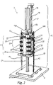
- the heating part 6 of the furnace 1 is preferably associated to a fixed structure 10 comprising a base 11, at least one screw 12 (or equivalent movement actuator with axis Z), of the recirculating ball or trapezia type, and a pressing element 13 arranged at a distance from such base 11.
- the pressing element 13 is made of material that is refractory material and with high coefficient of friction; it has a surface for contact with the billet preferably obtained with one or more projections suitable to "bite" the billet.
- the terminal part 13A of the pressing element may move in a floating fashion with respect to the vertical axis W of such element 13 (i.e. oscillating around the axis W) so as to adapt to possible inclinations of the free terminal parts of the billet at contact therewith with respect to such axis.
- the heating part 6 is suitable to hold the billet 2 during the heating thereof without the latter being subjected to any movement when in such part 6 there is generated the magnetic field for heating the billet by induction.
- the latter is in an absolutely fixed and stationary position in the part 2 during the heating thereof.
- Figures 1-3 show a first embodiment of the furnace 1. It has a heating part 6 mobile with respect to the base 11 along the guides 15 (vertical and lateral with respect to the part 6) which connect the base with a castle or structure 16 arranged above the base; the part 6 is associated with a threaded element (spiral) 600 fitted on the screw 12 which in turn rotates in the castle or structure 16 carrying the pressing element 13 through the action of a kinematic unit 18 made up of a motor, transmission or gear motor provided with a service brake on suitable gears (not shown) cooperating with the screw 12. In case of electrical power failure, the service brake is deactivated and the heating part 6 slides along the guides 15 by means of the screw 12 moved by the weight thereof, freeing the billet 2.
- a threaded element 600 fitted on the screw 12 which in turn rotates in the castle or structure 16 carrying the pressing element 13 through the action of a kinematic unit 18 made up of a motor, transmission or gear motor provided with a service brake on suitable gears (not shown) cooperating with
- the movement of the heating part 6 is obtained jointly with a lower flat portion 20 thereof and along a column 21.
- Such column supports a fixed end plate 21A suitable to cooperate with the pressing element 13 to hold the billet at a fixed position during the heating. This is facilitated by the surface of the pressing element 13 which is made of material with high coefficient of friction (for example of the type used for making brake pads) at contact with the billet.
- such plate 21A is also made of refractory material and it may floatingly oscillate to adapt to the surface of the billet 2 that rests thereon.
- At least one from among said plate 21A and said element 13 comprises means for measuring the temperature of the billet (for example, means operating at contact such as a thermocouple or from a distance such as optical pyrometers) which enable detecting the temperature thereof in the heating step and controlling the magnetic induction heating of the billet.
- means for measuring the temperature of the billet for example, means operating at contact such as a thermocouple or from a distance such as optical pyrometers
- Such control is carried out by a special unit for commanding and controlling the various functions of the furnace, not represented.
- the heating of the billet may be carried out according to zones and the temperature of the latter may be selected and evaluated (as described hereinafter).
- the measurement of the temperature is carried out preferably and for safety and control purposes: actually, knowing the characteristics of the material to be heated and the energy required to obtain such heating, it is possible to calculate the temperature reached by the billets without direct measurement thereof.
- the control unit also cooperates with an element suitable to measure the pressure exerted by the pressing element 13 on the billet.
- Such measurement element is advantageously, for example, a load cell. Thanks to the pressure data detected by such cell and the temperature data detected by temperature measurement means, the control unit adjusts the pressure exerted by the pressing element 13 as a function of the energy used for heating generated by the heating part 6.
- the pressure measurement element is also used for safety purposes for controlling the pressure exerted on the billet with the aim of avoiding deformation thereof (for extending the same when hot) and possible problems to the furnace as a whole.
- Such element is used to indirectly control the extension of the heated billet thus avoiding further over-pressure of the mechanical parts at contact therewith or deformations thereof capable of causing them to exceed the tolerances provided for by the requirements.
- the heating part 6 has lateral plates 22 supporting idler rollers or shoes 23 suitable to move along the lateral guides 15, so as to guide the movement of the heating part 6 towards the castle or structure 16.
- the heating part 6 of the furnace 1 comprises one or more (like in the example) heating sections 25 provided with coaxial (or annular) brushless electric motors 250, per se known (and which will be described hereinafter).
- every section 25 has a coaxial annular shape and it is superimposed and/or connected with other sections and thus delimits a central hole suitable to serve as a seat or compartment 27, with vertical axis W with respect to a plane P on which the furnace 1 lies, for the billet 2 when it is subjected to magnetic induction heating.
- a ring carrying permanent magnets in which the billet 2 is inserted is provided in each of such sections 25 and motors 250.
- various heating sections 25 are mutually axially superimposed (for example preferably being 2, 4, 6 or 8), each section having an annular motor 250 thereof; the entirety is arranged in a container 28 defined by the lower portion 20 and by the lateral plates 22 mentioned above, as well as by other plates 22A arranged on other sides of the part 6 different from those where the plates 26 are arranged.
- the container 28 is shaped to form a solid polygon (parallelepiped or cube, as a function of the number of sections 25 present) whose upper face 28A is open and delimited by the section placed at the top part of the stack of sections 25 present in the container.
- Such container is mobile, in its entirety, along the guides 15 towards the castle or structure 16 and thus receives in the seat or compartment 27 a billet arranged on a plate 21A which remains fixed in that integrally joined to the column 21 in turn integrally joined to the base 11.
- Such movement is obtained by rotating the screw 12 by means of the kinematic unit 18, said movement leading to the sliding of the threaded element 600 therealong and thus the movement of the part 6 along the guides 15.
- Such movement i.e. the sliding of the part 6 with respect to the base 11, is controlled by a linear transducer arranged in the castle or structure 16 (and not shown).
- such linear transducer is associated to the pressing element 13 so as to enable measuring the exact length of the billets through an initial movement of such element 13 after loading the billet into the furnace 1 which brings such element 13 to contact with the billet. This exploiting the fact that the plate 21A is fixed and it determines the reference plane.
- the control unit controls the lifting of the heating part 6 by rotating the screw 12 so that the displacement of said part 6 covers the actual length of the billet. It should be observed that such length is not constant (though established nominally), due to the fact that it derives from a previous billet cutting operation that does not always allow having a fixed and definite measurement of the billet.
- a pick-up arm that moves it from the furnace to a forging machine may always be positioned and grasp it at the most appropriate point with the aim of avoiding unbalancing thereof during the displacement thereof or to allow it to overcome possible obstacles present along the displacement path.
- the billet 2 can access the seat or compartment 27 from the face 28A, said compartment starting at such face and terminating at the portion 20 mentioned further above.
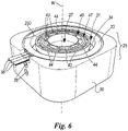
- each heating section 25 comprises an outer containment body 30 that is annular-shaped and having a central hole 31.
- the corresponding ring-shaped electric motor 250 is positioned in such hole.
- the motor 250 comprises a motor stator 33 and an inner motor rotor with permanent magnets 34.
- the stator 33 is electrically supplied through connectors 36 projecting from the containment body 30. In the latter, around the stator 33 there is present a cooling circuit (of the type with water, glycol or any other fluid) supplied through pipes connected to connections 38 present in the body 30.
- annular rotor 40 (or calibrator magnetic body which also serves as a spacer, which is cylindrical in the embodiment of the figures) defined by at least one annular body 41 containing an annular cylindrical member 41A with an axial hole and carrying a plurality of fixed permanent magnets 43 whose arrangement defines seats 44 that can be conveniently used as channels for cooling the magnets and applied to the body 41 thereof.
- the body 40 (or "annular magnetic rotor" considering such body 40 as a whole i.e. with the body 41, the member 41A and the magnets 43) rests on bearing members 47 interposed between the permanent magnet rotor 34 and the hollow portions 48 provided inside the body 41 in proximity of the juxtaposed ends thereof.
- the member 41A may have different embodiments with different axial holes thus defining seats or compartments 27 of different shape for the different billets.
- such rotor 40 may also be formed to shape a simple ring supporting the magnets 43 in suitable seats of the body thereof 41.
- the magnets are shaped "roof-tile-like" (and they are not a parallelepiped-shaped or cubic block) and this enables having high magnetic performance due to the fact that the magnetic flows completely enclose a corresponding support ring 41A and closing end covers 49B (which close each section 25), made of magnetically permeable material; in addition, thanks to such roof-tile-like shape, the aforementioned flows are conveniently directed towards the piece to be heated (billet 2) thus determining high penetration into the latter.
- Each section 25 comprises, as mentioned, the end covers for closing the bearings 49B and corresponding end magnetic flanges 49A suitable to close the magnetic field of the magnets (and maintain it in the group of the magnets 43) and a flange for supporting the bearings 49C.
- the magnets 43 are covered towards the seat or compartment 27, by an aluminium cylinder (not shown) as high as the group of magnets 43.
- Such cylinder is in turn covered by a layer (also not shown) made of infra-red radiations reflecting material suitable to break the same towards the billet arranged in the seat or compartment 27 thus protecting the magnets 43 against excessive heating.
- the rotors project from the containment body 30 and they are guided in rotation by a plurality of grooved discs 50 freely rotating on pins 51 fixed at angular portions 51A of such body. Every grooved disc 50 has a cavity 54 with which there cooperates a flange or collar 55 radially projecting from the corresponding rotor.
- the embodiment of the invention of figures 1-3 provides for that the heating part 6 be mobile along the guides 15 to carry out the heating of the billet.
- the heating part 6 rests on the base 11. Maintaining this configuration, a billet 2 is positioned (by a common handling device, not shown, outside the furnace 1) between the pressing element 13 and the plate 21A and the pressing element 13 is actuated to block such billet between it and the plate 21A.
- the pressing element 13 is defined by a hydraulic, pneumatic or hydropneumatic actuator with mobile plunge 13A suitable to press the billet 2 against the plate 21A.
- This also enables countering any and possible rotation reaction of the billet when the magnetic rotors 40 contained in the stations 25 are activated, the rotation being generated by the rotating magnetic field caused by the movement of the rotors 34 contained in the stators 33 of the aforementioned motors 250.
- Such rotation may be avoided, reduced or countered by alternating the direction of rotation of the rotors 34 of the motors 250 of adjacent and consecutive heating sections 25 from clockwise to anticlockwise rotation.
- the part 6 is thus lifted by the rotation of the screw 12 towards the castle or structure 16 until it covers the entire billet 2 i.e. until it is entirely into the seat or compartment 27.
- the entirety of the sections 25 stacked in the body 30 cover the entire length of the billet 2.
- thermocouples associated to the pressing element 13 and the plate 21A may be arranged between the various heating sections 25 so as to enable measuring temperature along the billet and not just on the two heads or ends only. This enables a better monitoring or control of the temperature trend i.e. the heating of the billet along the entire axis thereof.
- the motors 25 are deactivated and the part 6 is returned to the base 11; the billet thus heated (held by the element 13 on the plate 21A) is removed from the furnace 1 (for example by means of a handling device) and inserted, even directly, into an extruder through this or another handling device (not shown).
- the furnace 1 for example by means of a handling device
- the furnace may have small transversal dimensions (slightly bigger than one or two metres per side on the plane P) and be arranged on the side of the extruder, thus enabling quick loading of the heated billet into the latter.
- the billet may simply be placed on the plate 21A associated to the heating part 6 of the furnace 1 (and which is the part actually serving as a "furnace" of the latter) and preferably pressed on the plate 21A by the pressing element 13.
- the motors 250 used are of then ring-like coaxial type, as mentioned, and preferably they are advantageously of the three-phase synchronised type provided with a number of poles and windings necessary for optimising torque and having the required power.
- Such motors have a high performance at around 95%. They are "sensorless” i.e. they are not provided with transducers for setting the position of the rotor and the motor revolutions. Thanks to a calculation algorithm, the aforementioned control unit of the furnace provides the synchronisation of all motors 250 of the part 6 and their correct variation of the number of revolutions as a function of the temperature distribution requirement desired in the billet and possibly the cone temperature.
- Each magnetic rotor 40 has a number of poles not bound to a specific value and this number can be an even or odd number and greater than two in any case.
- the magnetic induction furnace in question has a high performance at around 95%.
- the magnets used Neodymium Iron Boron, NdFeB
- NdFeB Neodymium Iron Boron
- the part 6 of the furnace 1 is fixed to the base 11 while beneath the latter there is provided for a well or compartment 60 (obtained in a plane P on which such base lies) in proximity of which there is present a mobile support 61 for the billet 2.
- a mobile support 61 for the billet 2 is associated to an actuator 62 (for example a screw 63 driven by an electric motor 64) contained in such compartment 60.
- the support 61 is arranged in proximity of the base 11 i.e. of the lower portion 20 of the furnace 6 which - contrary to the embodiment of figures 1-3 - is provided with a central hole 66 coaxial with the seat or compartment 27 for the billet.
- such support (called axis Z) is raised in the seat or compartment 27 up to the upper face 28A of the container 28 of the part 6, through the actuator 62; there is thus positioned, on such support 61, the billet 2 which is thus pressed against the support of the pressing element 13.
- both the pressing element 13 and the actuator 62 move jointly along the axes Z and W of the seat or compartment 27 inserting the billet into the heating part 6 and holding it fixed and blocked in such seat. After the heating thereof (obtained using the heating sections 25), such movement is reverse repeated and the heated billet is removed from the seat or compartment 27 so as to be removed from the furnace.
- FIGS. 10-13 show a further variant of a furnace which is not part of the present invention.
- parts corresponding to those of the figures described previously are indicated using the same reference numbers.
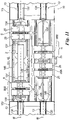
- the structure of the furnace is of the horizontal axis type in the sense that the heating part 6 is mobile parallel to the horizontal plane P on which the furnace lies.
- the figure shows a furnace 1 with two groups of heating parts 6 operating parallel or alternating with respect to each other (when one part heats, the other one is loaded with a billet 2 to be heated or an already heated billet is removed therefrom).
- the furnace 1 comprises a base 11 having end uprights 110 supporting pressing elements 13 (similar to that 13 of figure 1 already described), driven by linear actuators of the hydraulic, pneumatic or hydro-pneumatic type.
- Each pressing element has an actuator 130 and the mobile plunger 13A (carrying a body 131 suitable to cooperate with the billet 2 at an end thereof).
- the furnace 1 has pairs of mobile juxtaposed plungers 13A, coaxial at least placed on the same longitudinal axis M along the furnace 1.
- the heating parts 6 of the furnace that, in a preferred embodiment, comprise two portions 66A and 66B associated to carriages 140 mobile along guides 145 present on the base 11 move along such axis M.
- Such movement is obtained through per se known electromechanical (like of the screw type and a connected electric motor), hydraulic, pneumatic or hydropneumatic actuators.
- Each portion 66A and 66B comprises at least one heating section 25 provided with a coaxial motor 250 slidable, thanks to the inner compartment or seat 27, along the corresponding plungers 13A.
- a billet 2 may be carried by a handling device 300, for example a small overhead crane or carriage 310 moveable along overhead guides 311 and provided with its own means for actuating the movement; said handling device comprises mobile gripping members 313, for example a clamp, associated to a vertical movement member (for example a support arm or, a pulley, an overhead crane) 314 which enables taking a billet 2 (moved along the overhead guide 311 by the carriage 310) at the axis M when the juxtaposed pistons 13A are in a position such to space the bodies 131.
- a handling device 300 for example a small overhead crane or carriage 310 moveable along overhead guides 311 and provided with its own means for actuating the movement; said handling device comprises mobile gripping members 313, for example a clamp, associated to a vertical movement member (for example a support arm or, a pulley, an overhead crane) 314 which enables taking a billet 2 (moved along the overhead guide 311 by the carriage 310) at the axis M when the juxtapos
- the two portions 66A and 66B are enclosed around the billet and they are locked one on the other by means of lateral plates 370 associated to the outer containment body 30 of such heating sections 25. After heating, such portions 66A and 66B separate, each slide rises from the base, the elements 13 release the billet which can thus be removed.
- the invention enables obtaining a furnace that allows the non-uniform heating of the billet between one end and the other; this technique (or temperature cone) is required so as to obtain uniform temperature during extrusion.
- This possibility of heating the billet in a differentiated manner along the axis thereof derives from the use of a heating part 6 with electric motors which rotate at different speeds: the faster the rotation of the magnetic rotors 40 coaxial to the electric motors 250, the higher the temperature reached by the billet section arranged in such motor within the pre-established time unit.
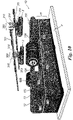
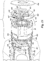
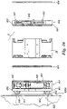
- Figures 14-16 show a particular application of the furnace of figure 1 which is not part of the present invention, to a common gas furnace 400. In such figures, parts corresponding to those described previously are indicated using the same reference numbers.
- guides 440 suitable to support the furnace 1. More in particular, the latter comprises a body 401 having guided elements 443 slidable on the guide 440 and clamp means 445 suitable to secure a billet (not shown) to the exit of the furnace.
- Such means 445 are of the clamp type and comprise an actuator 446, for example hydraulic, suitable to act on a return member 447 hinged to the body 401 and in turn acting on a rod 448 hinged to a first half-clamp 449.
- the other second half-clamp 450 is integrally joined to the return member 447 and it is hinged, similarly to what occurs with the first half-clamp 449, to a corresponding pin 451, 452 rising from a flat face 455 of the body 401.
- Brackets 463 supporting at least one heating section 25 of the furnace 1 detach from the upper 460 and lower 461 sides of the body 401.
- Such section is closed by another body 402 provided with clamp means like those 445 described above which will thus be indicated with the same reference numbers on the figures and which will not be described further.
- the fist (403) is interposed between the body 401 and the heating section 25 and the second (404) is arranged frontally i.e. on the vacant wall of the furnace 1. They respectively serve as a spacer and protection.
- the furnace 1 applied to the gas furnace 400 enables heating the end of the billet, already heated by the furnace 400 and exiting therefrom, at a temperature different from that of the gas furnace, thus enabling a cone-like heating of the billet (i.e. creating a cone temperature trend therein).
- the billet exiting from the furnace is secured by the half-clamps 449 and 450 of the clamp means 445 of the bodies 401 and 402 and held stationary while the section 25 heats it according to the methods described regarding the previous figures.
- the furnace 1 may be moved (for example through driving means not shown) on one side of the exit opening of the billet of the furnace 400.
Landscapes
- Engineering & Computer Science (AREA)
- Power Engineering (AREA)
- Physics & Mathematics (AREA)
- Electromagnetism (AREA)
- General Induction Heating (AREA)
- Furnace Details (AREA)
- Vertical, Hearth, Or Arc Furnaces (AREA)
- Extrusion Of Metal (AREA)
- Furnace Charging Or Discharging (AREA)
Claims (19)
- Four à induction magnétique (1) destiné au chauffage de billettes métalliques solides ou tubulaires (2) en matériau non ferreux devant être soumises à l'extrusion, le four à induction magnétique (1) comprenant une partie chauffante (6) dans laquelle est présente au moins une section chauffante (25) comprenant au moins un moteur électrique annulaire coaxial (250) équipé d'un stator de moteur fixe (33) et d'un rotor de moteur à aimant permanent (34) mobile dans ledit stator (33), la section chauffante (25) étant configurée pour contenir chaque billette (2) dans un état complètement stationnaire lorsqu'elle est insérée dans le four pendant toute l'opération de chauffage, où un rotor annulaire (40) portant une pluralité d'aimants permanents est prévu à l'intérieur de chaque moteur électrique annulaire coaxial, ledit rotor annulaire (40) étant coaxial audit stator de moteur (33) et au rotor de moteur (34) du moteur électrique annulaire coaxial (250) et définissant un compartiment (27) avec un axe vertical (W) par rapport à un plan (P) sur lequel repose le four (1), le rotor annulaire (40) étant configuré pour contenir au moins une billette (2) lorsqu'elle est chauffée par induction magnétique par le mouvement du rotor annulaire (40) contenu dans le rotor du moteur (34) du moteur électrique annulaire coaxial (250), ledit compartiment étant configuré pour contenir complètement la billette pendant l'opération de chauffage dans la position stable.
- Four selon la revendication 1, caractérisé en ce que le rotor annulaire (40) comprend un corps annulaire (41) contenant un élément cylindrique annulaire (41A) portant une pluralité d'aimants permanents fixes (43), l'agencement de l'élément cylindrique annulaire (41A) délimitant un trou axial définissant le compartiment (27) approprié pour contenir au moins une billette (2).
- Four selon la revendication 2, caractérisé en ce que les aimants (43) sont recouverts vers ledit compartiment (27) par un cylindre en aluminium qui est à son tour recouvert d'une couche faite d'un matériau réfléchissant les radiations infrarouges approprié pour protéger les aimants (43) contre un chauffage excessif.
- Four selon la revendication 1, caractérisé en ce qu'il comprend une pluralité de sections chauffantes (25), chacune de ces sections comprenant un moteur électrique annulaire coaxial (250) contenant un rotor annulaire (40) portant les aimants permanents (43), les sections chauffantes étant superposées les unes aux autres et délimitant le compartiment (27) pour la billette (2) avec leur rotor annulaire (40).
- Four selon la revendication 4, caractérisé en ce que les moteurs électriques annulaires (250) de la pluralité de sections chauffantes (25) tournent à des vitesses différentes de sorte que leurs rotors annulaires correspondants (40) génèrent des lignes de flux magnétique différentes et produisent un chauffage non uniforme de la billette.
- Four selon la revendication 1, caractérisé en ce que la partie chauffante (6) est associée à une structure fixe (10) comprenant une base (11), et au moins un élément de pression (13) séparé de cette partie chauffante (6) et adapté pour maintenir ladite billette (2) bloquée pendant le chauffage.
- Four selon la revendication 6, caractérisé en ce que la partie chauffante (6) est mobile par rapport à une telle structure fixe (10).
- Four selon la revendication 7, caractérisé en ce qu'il existe des guides verticaux (15) par rapport audit plan (P) reliant la base (11) à une structure (16) portant l'élément presseur (13), ladite partie chauffante (6) se déplaçant le long de ces guides, des moyens d'actionnement (12, 18) associés à cette structure (16) et des moyens guidés (600) associés à la partie chauffante (6) étant prévus pour déplacer ladite partie le long desdits guides (15).
- Four selon la revendication 8, caractérisé en ce que lesdits moyens d'actionnement (12) sont une vis entraînée par un moteur électrique (18) de manière contrôlée, les moyens guidés étant un élément fileté (600) associé à ladite partie chauffante (6) se déplaçant sur ladite vis (12).
- Four selon la revendication 6, caractérisé en ce que ledit élément presseur (13) comprend un organe (13A) mobile par rapport à une plaque fixe (21A) solidaire d'une colonne sur laquelle se déplace la partie chauffante (6) de manière à maintenir cette billette bloquée entre ladite plaque et ledit organe mobile (13A) pendant son chauffage.
- Four selon la revendication 6, caractérisé en ce qu'il est prévu deux éléments presseurs (13) disposés en positions juxtaposées par rapport à la base (11) dont l'un est au moins mobile sur cette base pour maintenir une billette pendant le chauffage et disposé parallèlement au plan (P) sur lequel repose ladite base.
- Four selon la revendication 6, caractérisé en ce que la partie chauffante (6) est statique par rapport à la structure fixe (10), des moyens étant prévus pour déplacer la billette (2) mobile dans le compartiment (27) et adaptés pour introduire dans cette partie chauffante la billette (2) pour la chauffer lorsque la billette est bloquée dans le compartiment (27), lesdits moyens de déplacement étant adaptés pour être approchés de l'élément de pression (13) dans le but de recevoir la billette (2) pour la chauffer ou la préparer pour l'enlever du four (1).
- Four selon la revendication 12, caractérisé en ce que ces moyens de déplacement comprennent un support (61) mobile dans ledit compartiment (27) et des moyens (62) d'actionnement de ce déplacement placés sous la partie chauffante (6) du four.
- Four selon la revendication 13, caractérisé en ce que ces moyens d'actionnement sont alternativement du type hydraulique, pneumatique, hydro-pneumatique ou mécanique avec un mouvement généré par un moteur électrique.
- Four selon la revendication 13, caractérisé en ce que lesdits moyens d'actionnement sont disposés dans un compartiment (60) présent sous le plan (P) sur lequel repose la partie chauffante (6) du four.
- Four selon la revendication 1, caractérisé en ce que le rotor annulaire (40) est choisi parmi une pluralité de rotors (40) de manière à uniformiser la dimension radiale du compartiment (27) apte à contenir la billette (2) à la dimension radiale de cette dernière, ledit rotor annulaire (40) supportant une pluralité d'aimants permanents fixes (43) de préférence en forme de tuile.
- Four selon la revendication 1, caractérisé en ce qu'il est prévu des moyens de détection de température appropriés pour mesurer la température d'une ou plusieurs zones de la billette.
- Four selon la revendication 10, caractérisé en ce qu'il est prévu des moyens de mesure de distance entre l'élément presseur (13) et la plaque fixe (21A) et adaptés pour détecter la dimension réelle de la billette (2) dans le sens de la longueur.
- Four selon les revendications 17 et 18, caractérisé en ce qu'il est prévu une unité de commande apte à contrôler le mouvement relatif de la partie chauffante (6) par rapport à la billette (2) et la vitesse de rotation de chaque moteur coaxial (250) en fonction de la mesure de température et/ou de la distance effectuée.
Applications Claiming Priority (2)
| Application Number | Priority Date | Filing Date | Title |
|---|---|---|---|
| ITUB2015A005468A ITUB20155468A1 (it) | 2015-11-11 | 2015-11-11 | Forno ad induzione magnetica per riscaldare billette metalliche in materiali non ferrosi da sottoporre a estrusione |
| PCT/IB2016/001622 WO2017081532A1 (fr) | 2015-11-11 | 2016-11-11 | Four à induction magnétique approprié pour chauffer des billettes métalliques de matière non ferreuse à extruder |
Publications (2)
| Publication Number | Publication Date |
|---|---|
| EP3375252A1 EP3375252A1 (fr) | 2018-09-19 |
| EP3375252B1 true EP3375252B1 (fr) | 2022-07-20 |
Family
ID=55446923
Family Applications (1)
| Application Number | Title | Priority Date | Filing Date |
|---|---|---|---|
| EP16812817.1A Active EP3375252B1 (fr) | 2015-11-11 | 2016-11-11 | Four à induction magnétique approprié pour chauffer des billettes métalliques de matière non ferreuse à extruder |
Country Status (6)
| Country | Link |
|---|---|
| EP (1) | EP3375252B1 (fr) |
| JP (2) | JP6929839B2 (fr) |
| ES (1) | ES2928166T3 (fr) |
| IT (1) | ITUB20155468A1 (fr) |
| PL (1) | PL3375252T3 (fr) |
| WO (1) | WO2017081532A1 (fr) |
Families Citing this family (4)
| Publication number | Priority date | Publication date | Assignee | Title |
|---|---|---|---|---|
| KR102231857B1 (ko) * | 2017-07-11 | 2021-03-24 | 한국전기연구원 | 자가발전 무선온도 및 위치 진단 기능을 갖는 영구자석 금속 빌렛 유도가열 장치 |
| JP7629100B2 (ja) * | 2020-12-14 | 2025-02-12 | ノベリス・インコーポレイテッド | 熱処理を伴うロール成形システム及び関連する方法 |
| IT202200026502A1 (it) | 2022-12-22 | 2024-06-22 | Presezzi Extrusion S P A | Impianto per il riscaldamento di billette di materiali non ferrosi |
| CN118785558B (zh) * | 2024-09-09 | 2025-03-28 | 江西联创光电超导应用有限公司 | 加热装置及其控制方法 |
Citations (1)
| Publication number | Priority date | Publication date | Assignee | Title |
|---|---|---|---|---|
| WO2013128241A1 (fr) * | 2012-03-01 | 2013-09-06 | Inova Lab S.R.L. | Dispositif pour chauffage par induction d'une billette |
Family Cites Families (6)
| Publication number | Priority date | Publication date | Assignee | Title |
|---|---|---|---|---|
| JPS532433U (fr) * | 1976-06-25 | 1978-01-11 | ||
| DE102007039888B4 (de) * | 2007-08-23 | 2010-01-28 | Zenergy Power Gmbh | Verfahren und Vorrichtung zur Induktionserwärmung eines metallischen Werkstücks |
| DE102007051108B4 (de) * | 2007-10-24 | 2010-07-15 | Zenergy Power Gmbh | Verfahren zum induktiven Erwärmen eines metallischen Werkstücks |
| FI20095213A0 (fi) * | 2009-03-04 | 2009-03-04 | Prizztech Oy | Induktiokuumennusmenetelmä ja -laitteisto |
| EP3199647B1 (fr) * | 2010-10-11 | 2019-07-31 | The Timken Company | Appareil de durcissement par induction |
| US8993942B2 (en) * | 2010-10-11 | 2015-03-31 | The Timken Company | Apparatus for induction hardening |
-
2015
- 2015-11-11 IT ITUB2015A005468A patent/ITUB20155468A1/it unknown
-
2016
- 2016-11-11 ES ES16812817T patent/ES2928166T3/es active Active
- 2016-11-11 PL PL16812817.1T patent/PL3375252T3/pl unknown
- 2016-11-11 EP EP16812817.1A patent/EP3375252B1/fr active Active
- 2016-11-11 JP JP2018521428A patent/JP6929839B2/ja active Active
- 2016-11-11 WO PCT/IB2016/001622 patent/WO2017081532A1/fr not_active Ceased
-
2021
- 2021-08-06 JP JP2021129525A patent/JP7176064B2/ja active Active
Patent Citations (1)
| Publication number | Priority date | Publication date | Assignee | Title |
|---|---|---|---|---|
| WO2013128241A1 (fr) * | 2012-03-01 | 2013-09-06 | Inova Lab S.R.L. | Dispositif pour chauffage par induction d'une billette |
Also Published As
| Publication number | Publication date |
|---|---|
| JP6929839B2 (ja) | 2021-09-01 |
| JP2021177500A (ja) | 2021-11-11 |
| WO2017081532A1 (fr) | 2017-05-18 |
| ES2928166T3 (es) | 2022-11-15 |
| JP7176064B2 (ja) | 2022-11-21 |
| HK1259419A1 (en) | 2019-11-29 |
| ITUB20155468A1 (it) | 2017-05-11 |
| EP3375252A1 (fr) | 2018-09-19 |
| JP2019502226A (ja) | 2019-01-24 |
| PL3375252T3 (pl) | 2022-12-19 |
Similar Documents
| Publication | Publication Date | Title |
|---|---|---|
| JP7176064B2 (ja) | 非鉄金属材料の加熱金属ビレットに適した磁気誘導炉 | |
| RU2709494C1 (ru) | Компактная линия гомогенизации непрерывным отжигом | |
| KR101024181B1 (ko) | 스테이터 코일의 가열 장치 및 가열 방법 | |
| US10129933B2 (en) | Induction coil unit | |
| KR102594176B1 (ko) | 전기 기계의 고정자 또는 전기자의 트리클 함침을 위한 장치 | |
| CA2688069C (fr) | Appareil de chauffage par induction | |
| KR101544091B1 (ko) | 수직이동 냉각방식의 열처리장치 | |
| CN106170568B (zh) | 用于在环底平炉中对细长扁平的金属物料、尤其是轧制铝锭进行热处理的方法和设备 | |
| EP3054020A1 (fr) | Procédé de traitement thermique pour un élément annulaire et équipement de traitement thermique pour un élément annulaire | |
| CN105579176B (zh) | 使用被构造为电动液压直接驱动器的进给驱动器的压焊设备和压焊方法 | |
| KR20190060796A (ko) | 회전 자석 열 유도 | |
| KR20190006782A (ko) | 자가발전 무선온도 및 위치 진단 기능을 갖는 영구자석 금속 빌렛 유도가열 장치 | |
| HK1259419B (en) | Magnetic induction furnace suitable to heat metallic billets of non-ferrous material to be extruded | |
| JP2008502297A (ja) | 駆動装置 | |
| CN120555714A (zh) | 一种钢质电机轴制造热处理设备 | |
| CN104575862B (zh) | 使绝缘导体成形和退火的方法 | |
| CN116038260B (zh) | 一种高速径向可倾瓦支承轴承导瓦加工工艺 | |
| CN219156908U (zh) | 一种金相线材自动退火炉 | |
| JP2005525938A5 (fr) | ||
| JP2020117768A (ja) | モータコアの焼鈍装置及びモータコアの焼鈍方法 | |
| CN119384319A (zh) | 用于电动马达部件的浸渍设备及用于对各个部件进行支撑和操纵的其相应的装备 | |
| WO2024134519A1 (fr) | Système de chauffage de billettes de matériaux non ferreux | |
| CN111560511A (zh) | 一种金属表面热处理用高效稳定化处理装置 | |
| CN223124758U (zh) | 一种电机机筒加热测温装置 | |
| CN210237720U (zh) | 一种轴承加工用精密热处理设备 |
Legal Events
| Date | Code | Title | Description |
|---|---|---|---|
| STAA | Information on the status of an ep patent application or granted ep patent |
Free format text: STATUS: UNKNOWN |
|
| STAA | Information on the status of an ep patent application or granted ep patent |
Free format text: STATUS: THE INTERNATIONAL PUBLICATION HAS BEEN MADE |
|
| TPAC | Observations filed by third parties |
Free format text: ORIGINAL CODE: EPIDOSNTIPA |
|
| PUAI | Public reference made under article 153(3) epc to a published international application that has entered the european phase |
Free format text: ORIGINAL CODE: 0009012 |
|
| STAA | Information on the status of an ep patent application or granted ep patent |
Free format text: STATUS: REQUEST FOR EXAMINATION WAS MADE |
|
| 17P | Request for examination filed |
Effective date: 20180607 |
|
| AK | Designated contracting states |
Kind code of ref document: A1 Designated state(s): AL AT BE BG CH CY CZ DE DK EE ES FI FR GB GR HR HU IE IS IT LI LT LU LV MC MK MT NL NO PL PT RO RS SE SI SK SM TR |
|
| AX | Request for extension of the european patent |
Extension state: BA ME |
|
| DAV | Request for validation of the european patent (deleted) | ||
| DAX | Request for extension of the european patent (deleted) | ||
| REG | Reference to a national code |
Ref country code: HK Ref legal event code: DE Ref document number: 1259419 Country of ref document: HK |
|
| STAA | Information on the status of an ep patent application or granted ep patent |
Free format text: STATUS: EXAMINATION IS IN PROGRESS |
|
| 17Q | First examination report despatched |
Effective date: 20200910 |
|
| GRAP | Despatch of communication of intention to grant a patent |
Free format text: ORIGINAL CODE: EPIDOSNIGR1 |
|
| STAA | Information on the status of an ep patent application or granted ep patent |
Free format text: STATUS: GRANT OF PATENT IS INTENDED |
|
| INTG | Intention to grant announced |
Effective date: 20220222 |
|
| GRAS | Grant fee paid |
Free format text: ORIGINAL CODE: EPIDOSNIGR3 |
|
| GRAA | (expected) grant |
Free format text: ORIGINAL CODE: 0009210 |
|
| STAA | Information on the status of an ep patent application or granted ep patent |
Free format text: STATUS: THE PATENT HAS BEEN GRANTED |
|
| AK | Designated contracting states |
Kind code of ref document: B1 Designated state(s): AL AT BE BG CH CY CZ DE DK EE ES FI FR GB GR HR HU IE IS IT LI LT LU LV MC MK MT NL NO PL PT RO RS SE SI SK SM TR |
|
| REG | Reference to a national code |
Ref country code: CH Ref legal event code: EP |
|
| REG | Reference to a national code |
Ref country code: DE Ref legal event code: R096 Ref document number: 602016073665 Country of ref document: DE |
|
| REG | Reference to a national code |
Ref country code: AT Ref legal event code: REF Ref document number: 1506413 Country of ref document: AT Kind code of ref document: T Effective date: 20220815 |
|
| REG | Reference to a national code |
Ref country code: IE Ref legal event code: FG4D |
|
| REG | Reference to a national code |
Ref country code: FI Ref legal event code: FGE |
|
| REG | Reference to a national code |
Ref country code: LT Ref legal event code: MG9D |
|
| REG | Reference to a national code |
Ref country code: ES Ref legal event code: FG2A Ref document number: 2928166 Country of ref document: ES Kind code of ref document: T3 Effective date: 20221115 |
|
| REG | Reference to a national code |
Ref country code: NL Ref legal event code: MP Effective date: 20220720 |
|
| PG25 | Lapsed in a contracting state [announced via postgrant information from national office to epo] |
Ref country code: SE Free format text: LAPSE BECAUSE OF FAILURE TO SUBMIT A TRANSLATION OF THE DESCRIPTION OR TO PAY THE FEE WITHIN THE PRESCRIBED TIME-LIMIT Effective date: 20220720 Ref country code: RS Free format text: LAPSE BECAUSE OF FAILURE TO SUBMIT A TRANSLATION OF THE DESCRIPTION OR TO PAY THE FEE WITHIN THE PRESCRIBED TIME-LIMIT Effective date: 20220720 Ref country code: PT Free format text: LAPSE BECAUSE OF FAILURE TO SUBMIT A TRANSLATION OF THE DESCRIPTION OR TO PAY THE FEE WITHIN THE PRESCRIBED TIME-LIMIT Effective date: 20221121 Ref country code: NO Free format text: LAPSE BECAUSE OF FAILURE TO SUBMIT A TRANSLATION OF THE DESCRIPTION OR TO PAY THE FEE WITHIN THE PRESCRIBED TIME-LIMIT Effective date: 20221020 Ref country code: NL Free format text: LAPSE BECAUSE OF FAILURE TO SUBMIT A TRANSLATION OF THE DESCRIPTION OR TO PAY THE FEE WITHIN THE PRESCRIBED TIME-LIMIT Effective date: 20220720 Ref country code: LV Free format text: LAPSE BECAUSE OF FAILURE TO SUBMIT A TRANSLATION OF THE DESCRIPTION OR TO PAY THE FEE WITHIN THE PRESCRIBED TIME-LIMIT Effective date: 20220720 Ref country code: LT Free format text: LAPSE BECAUSE OF FAILURE TO SUBMIT A TRANSLATION OF THE DESCRIPTION OR TO PAY THE FEE WITHIN THE PRESCRIBED TIME-LIMIT Effective date: 20220720 |
|
| PG25 | Lapsed in a contracting state [announced via postgrant information from national office to epo] |
Ref country code: IS Free format text: LAPSE BECAUSE OF FAILURE TO SUBMIT A TRANSLATION OF THE DESCRIPTION OR TO PAY THE FEE WITHIN THE PRESCRIBED TIME-LIMIT Effective date: 20221120 Ref country code: HR Free format text: LAPSE BECAUSE OF FAILURE TO SUBMIT A TRANSLATION OF THE DESCRIPTION OR TO PAY THE FEE WITHIN THE PRESCRIBED TIME-LIMIT Effective date: 20220720 Ref country code: GR Free format text: LAPSE BECAUSE OF FAILURE TO SUBMIT A TRANSLATION OF THE DESCRIPTION OR TO PAY THE FEE WITHIN THE PRESCRIBED TIME-LIMIT Effective date: 20221021 |
|
| REG | Reference to a national code |
Ref country code: DE Ref legal event code: R097 Ref document number: 602016073665 Country of ref document: DE |
|
| PG25 | Lapsed in a contracting state [announced via postgrant information from national office to epo] |
Ref country code: SM Free format text: LAPSE BECAUSE OF FAILURE TO SUBMIT A TRANSLATION OF THE DESCRIPTION OR TO PAY THE FEE WITHIN THE PRESCRIBED TIME-LIMIT Effective date: 20220720 Ref country code: RO Free format text: LAPSE BECAUSE OF FAILURE TO SUBMIT A TRANSLATION OF THE DESCRIPTION OR TO PAY THE FEE WITHIN THE PRESCRIBED TIME-LIMIT Effective date: 20220720 Ref country code: DK Free format text: LAPSE BECAUSE OF FAILURE TO SUBMIT A TRANSLATION OF THE DESCRIPTION OR TO PAY THE FEE WITHIN THE PRESCRIBED TIME-LIMIT Effective date: 20220720 Ref country code: CZ Free format text: LAPSE BECAUSE OF FAILURE TO SUBMIT A TRANSLATION OF THE DESCRIPTION OR TO PAY THE FEE WITHIN THE PRESCRIBED TIME-LIMIT Effective date: 20220720 |
|
| PLBE | No opposition filed within time limit |
Free format text: ORIGINAL CODE: 0009261 |
|
| STAA | Information on the status of an ep patent application or granted ep patent |
Free format text: STATUS: NO OPPOSITION FILED WITHIN TIME LIMIT |
|
| PG25 | Lapsed in a contracting state [announced via postgrant information from national office to epo] |
Ref country code: SK Free format text: LAPSE BECAUSE OF FAILURE TO SUBMIT A TRANSLATION OF THE DESCRIPTION OR TO PAY THE FEE WITHIN THE PRESCRIBED TIME-LIMIT Effective date: 20220720 Ref country code: EE Free format text: LAPSE BECAUSE OF FAILURE TO SUBMIT A TRANSLATION OF THE DESCRIPTION OR TO PAY THE FEE WITHIN THE PRESCRIBED TIME-LIMIT Effective date: 20220720 |
|
| 26N | No opposition filed |
Effective date: 20230421 |
|
| PG25 | Lapsed in a contracting state [announced via postgrant information from national office to epo] |
Ref country code: MC Free format text: LAPSE BECAUSE OF FAILURE TO SUBMIT A TRANSLATION OF THE DESCRIPTION OR TO PAY THE FEE WITHIN THE PRESCRIBED TIME-LIMIT Effective date: 20220720 Ref country code: AL Free format text: LAPSE BECAUSE OF FAILURE TO SUBMIT A TRANSLATION OF THE DESCRIPTION OR TO PAY THE FEE WITHIN THE PRESCRIBED TIME-LIMIT Effective date: 20220720 |
|
| P01 | Opt-out of the competence of the unified patent court (upc) registered |
Effective date: 20230602 |
|
| REG | Reference to a national code |
Ref country code: AT Ref legal event code: UEP Ref document number: 1506413 Country of ref document: AT Kind code of ref document: T Effective date: 20220720 |
|
| PG25 | Lapsed in a contracting state [announced via postgrant information from national office to epo] |
Ref country code: SI Free format text: LAPSE BECAUSE OF FAILURE TO SUBMIT A TRANSLATION OF THE DESCRIPTION OR TO PAY THE FEE WITHIN THE PRESCRIBED TIME-LIMIT Effective date: 20220720 Ref country code: LU Free format text: LAPSE BECAUSE OF NON-PAYMENT OF DUE FEES Effective date: 20221111 |
|
| PG25 | Lapsed in a contracting state [announced via postgrant information from national office to epo] |
Ref country code: IE Free format text: LAPSE BECAUSE OF NON-PAYMENT OF DUE FEES Effective date: 20221111 |
|
| PG25 | Lapsed in a contracting state [announced via postgrant information from national office to epo] |
Ref country code: FR Free format text: LAPSE BECAUSE OF NON-PAYMENT OF DUE FEES Effective date: 20221130 |
|
| PG25 | Lapsed in a contracting state [announced via postgrant information from national office to epo] |
Ref country code: HU Free format text: LAPSE BECAUSE OF FAILURE TO SUBMIT A TRANSLATION OF THE DESCRIPTION OR TO PAY THE FEE WITHIN THE PRESCRIBED TIME-LIMIT; INVALID AB INITIO Effective date: 20161111 |
|
| PG25 | Lapsed in a contracting state [announced via postgrant information from national office to epo] |
Ref country code: CY Free format text: LAPSE BECAUSE OF FAILURE TO SUBMIT A TRANSLATION OF THE DESCRIPTION OR TO PAY THE FEE WITHIN THE PRESCRIBED TIME-LIMIT Effective date: 20220720 |
|
| PG25 | Lapsed in a contracting state [announced via postgrant information from national office to epo] |
Ref country code: MK Free format text: LAPSE BECAUSE OF FAILURE TO SUBMIT A TRANSLATION OF THE DESCRIPTION OR TO PAY THE FEE WITHIN THE PRESCRIBED TIME-LIMIT Effective date: 20220720 |
|
| PG25 | Lapsed in a contracting state [announced via postgrant information from national office to epo] |
Ref country code: BG Free format text: LAPSE BECAUSE OF FAILURE TO SUBMIT A TRANSLATION OF THE DESCRIPTION OR TO PAY THE FEE WITHIN THE PRESCRIBED TIME-LIMIT Effective date: 20220720 |
|
| PG25 | Lapsed in a contracting state [announced via postgrant information from national office to epo] |
Ref country code: MT Free format text: LAPSE BECAUSE OF FAILURE TO SUBMIT A TRANSLATION OF THE DESCRIPTION OR TO PAY THE FEE WITHIN THE PRESCRIBED TIME-LIMIT Effective date: 20220720 |
|
| REG | Reference to a national code |
Ref country code: CH Ref legal event code: U11 Free format text: ST27 STATUS EVENT CODE: U-0-0-U10-U11 (AS PROVIDED BY THE NATIONAL OFFICE) Effective date: 20251201 |
|
| PGFP | Annual fee paid to national office [announced via postgrant information from national office to epo] |
Ref country code: DE Payment date: 20251118 Year of fee payment: 10 |
|
| PGFP | Annual fee paid to national office [announced via postgrant information from national office to epo] |
Ref country code: GB Payment date: 20251119 Year of fee payment: 10 |
|
| PGFP | Annual fee paid to national office [announced via postgrant information from national office to epo] |
Ref country code: AT Payment date: 20251128 Year of fee payment: 10 |
|
| PGFP | Annual fee paid to national office [announced via postgrant information from national office to epo] |
Ref country code: FI Payment date: 20251125 Year of fee payment: 10 Ref country code: IT Payment date: 20251023 Year of fee payment: 10 |
|
| PGFP | Annual fee paid to national office [announced via postgrant information from national office to epo] |
Ref country code: TR Payment date: 20251023 Year of fee payment: 10 Ref country code: BE Payment date: 20251127 Year of fee payment: 10 |
|
| PGFP | Annual fee paid to national office [announced via postgrant information from national office to epo] |
Ref country code: CH Payment date: 20251201 Year of fee payment: 10 |
|
| PGFP | Annual fee paid to national office [announced via postgrant information from national office to epo] |
Ref country code: PL Payment date: 20251024 Year of fee payment: 10 |
|
| PGFP | Annual fee paid to national office [announced via postgrant information from national office to epo] |
Ref country code: ES Payment date: 20251201 Year of fee payment: 10 |