EP3375271B1 - Landwirtschaftliche maschine zur bodenbearbeitung, die mindestens zwei wechselseitig versetzte scheibenreihen umfasst, deren position in vorwärtsrichtung verstellbar ist - Google Patents
Landwirtschaftliche maschine zur bodenbearbeitung, die mindestens zwei wechselseitig versetzte scheibenreihen umfasst, deren position in vorwärtsrichtung verstellbar ist Download PDFInfo
- Publication number
- EP3375271B1 EP3375271B1 EP18305280.2A EP18305280A EP3375271B1 EP 3375271 B1 EP3375271 B1 EP 3375271B1 EP 18305280 A EP18305280 A EP 18305280A EP 3375271 B1 EP3375271 B1 EP 3375271B1
- Authority
- EP
- European Patent Office
- Prior art keywords
- train
- chassis
- implements
- agricultural machine
- machine according
- Prior art date
- Legal status (The legal status is an assumption and is not a legal conclusion. Google has not performed a legal analysis and makes no representation as to the accuracy of the status listed.)
- Active
Links
Images


Classifications
-
- A—HUMAN NECESSITIES
- A01—AGRICULTURE; FORESTRY; ANIMAL HUSBANDRY; HUNTING; TRAPPING; FISHING
- A01B—SOIL WORKING IN AGRICULTURE OR FORESTRY; PARTS, DETAILS, OR ACCESSORIES OF AGRICULTURAL MACHINES OR IMPLEMENTS, IN GENERAL
- A01B21/00—Harrows with rotary non-driven tools
- A01B21/08—Harrows with rotary non-driven tools with disc-like tools
-
- A—HUMAN NECESSITIES
- A01—AGRICULTURE; FORESTRY; ANIMAL HUSBANDRY; HUNTING; TRAPPING; FISHING
- A01B—SOIL WORKING IN AGRICULTURE OR FORESTRY; PARTS, DETAILS, OR ACCESSORIES OF AGRICULTURAL MACHINES OR IMPLEMENTS, IN GENERAL
- A01B49/00—Combined machines
- A01B49/02—Combined machines with two or more soil-working tools of different kind
- A01B49/027—Combined machines with two or more soil-working tools of different kind with a rotating, soil working support element, e.g. a roller
Definitions
- the present invention relates to the field of agricultural machinery, more particularly soil treatment machines, in particular machines for soil preparation after harvest and before sowing, such as disc harrows.
- the subject of the invention is such an agricultural machine, carried or towed, which can adapt to different working conditions, in order to carry out an effective treatment while allowing a high working speed.
- These known soil treatment machines generally comprise a chassis and at least two trains of working tools in the form of rotating discs, each train forming an alignment of tools in one or more parts extending substantially transversely to the direction. normal advance of the machine in use. Said trains are mutually offset in the direction of advance, the set of tools of a given train, or at least part of a train, being mounted directly or indirectly on a common support member connected to the chassis.
- the rotary discs are for example mounted by hubs and bearings on guide arms, themselves fixed on an elongated support member, such as a transverse beam or a cross member to form together a train of discs.
- the different (generally two) sets of discs can be arranged parallel to each other and perpendicular to the normal direction of advance of the machine in use, but not necessarily. They can also be inclined relative to each other and / or to the direction of advance.
- Rotary discs rigidly secured or not to their support, have a certain angle of attack, which determines the quality of the tillage by these discs, generally concave / convex in shape and provided with teeth on their periphery.
- these rotary disc trains can be in one piece (small working width) or be segmented into at least two or three parts (large working width), possibly connected in an articulated manner.
- this type of soil treatment machines can create waves / undulations linked to a particular projection of the earth from the first train of discs to the second at a given speed.
- This phenomenon can create instability laterally as well as vertically as well as jams in the presence of plant debris.
- there is a non-homogeneous soil / residue mixture which makes the seedbed unfavorable for germination.
- this reduction in speed has a direct impact on the quality of work and the work rate.
- the main object of the invention is to provide a machine which can adapt to different conditions of work (soil flow, quantity of residues, ...), by creating and maintaining a homogeneous soil / residue mixture, and making it possible to preserve a good quality of work and / or to maintain a determined thickness of treatment, it that is to say to create a homogeneous seed bed, while maintaining an optimum speed of advance for the farmer.
- the subject of the invention is an agricultural soil treatment machine as mentioned in the introduction to the present, and which is characterized in that at least one of the support members is connected to the chassis via at least one deformable mechanical connection, allowing a modification of the relative position of the train, or of the train part, considered with respect to the chassis in the direction of advance, this under the action of at least an adjustment member, for example manual, assisted or motorized.
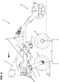
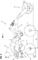
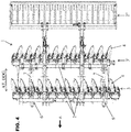
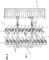
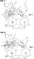
- the figures 1 to 8 attached drawings show an agricultural machine 1 for soil treatment comprising a chassis 2 and at least two trains 3, 3 'of working tools 4 in the form of rotating discs.
- Each train 3, 3 ' forms an alignment of tools 4 in one or more parts extending substantially transversely relative to the normal direction of advance A of the machine 1 in use and said trains 3, 3' are mutually offset in the direction of advance A, the set of tools 4 of a given train 3, 3 ′, or of a train part at least, being mounted directly or indirectly on a common support member 5 connected to the chassis 2.
- the two trains 3, 3 'of discs are arranged parallel to each other.
- the two sets of discs can be arranged inclined with respect to each other and / or with respect to the direction of advance A.
- At least one of the support members 5 is connected to the chassis 2 by means of at least one deformable mechanical connection 6, allowing a modification of the relative position of the train 3, 3 ′, or of the train part, considered with respect to the chassis 2 in the direction of advance A, this under the action of at least one adjusting member 7, manual or assisted.
- This member can advantageously be supplied with power, and preferably consists of a jack or a mechanical, hydraulic or electric tie rod.
- the invention it is possible to easily adapt the configuration of the machine 1 to the working conditions encountered in the field. Indeed, by modifying the spacing between the trains 3, 3 ′ of tools 4, by modifying the configuration of the deformable link (s) 6, the harmful consequences are avoided (mixtures of soil / plant residues not homogeneous, waves, machine instability, jams ...), keeping the optimum speed.
- the deformation of the mechanical link (s) 6, under the action of the adjustment member (s) 7, preserves the angle of attack ⁇ of the tools 4, in the form of rotating discs , who belong to the train 3, 3 'concerned by the induced relative position modification.
- the deformation of the mechanical link (s) 6, under the action of the adjustment member or members 7, preserves, at least considering the two extreme positions of displacement, the working depth of tools 4, in the form of rotating discs, which belong to the train 3, 3 'concerned by the change in relative position induced.
- said at least one deformable link 6 is configured to achieve, under the controlled action of at least one controlled adjustment member 7, a guided movement of the tool train 3, 3 'or the part of the train 3, 3 ′ considered, this parallel to the direction of advance A and relatively with respect to the chassis 2 and to another train or part of the train 3, 3 ′, so as to modify their relative spacing in the direction of advance A.
- the chassis 2 of the machine 1 can for example consist of two transverse beams connected by side members.
- the coupling 2 ' is fixed to or forms part of the chassis 2 and the latter can also carry on the rear at least one additional equipment 2 "comprising, for example, a soil working tool, such as for example a lifting harrow , and / or an adjustable rolling means.
- the or at least one of the deformable connections with guide 6 consists of a slide connection.
- the or at least one of the deformable links with guide 6 consists of a pendulum kinematics, for example consisting of two links 8 connected by pivot links 8 'to the chassis 2 on the one hand, and to support member 5 of train or the relevant part of the train, on the other hand.
- This pendulum kinematics represents a quadrilateral.
- the pendulum kinematics is advantageously a parallelogram.
- all those associated with a given train are preferably of the same type, for example sliding with slides or translational by deformation (cf. for example figures 1 and 4 ).
- the or each adjusting member 7 is of translative type, the translational actuation direction AT of which is advantageously parallel to the direction of movement DDG resulting from a guided deformation of the link or links 6 connecting the train 3, 3 ′ of tools 4 or the part of train 3 , 3 'considered and chassis 2.
- the train (s) 3, 3' of tools 4 mobile (s ) relative to the frame 2 itself (s) connected (s) to the frame 2 by two deformable links with guide 6, located near the opposite lateral ends of the support member 5 of the train 3, 3 'considered, the deformation of said links 6 and therefore the relative movement of the train 3, 3 'considered being provided by a single adjusting member 7 positioned substantially centrally with respect to the train 3, 3' considered.
- the train (s) 3, 3 ′ of tools 4 mobile (s) relative to the chassis 2 may be connected ) to the chassis 2 by at least two deformable links with guide 6, with each link 6 being associated with a translative adjustment member 7 located nearby, the actuation axis AT of the latter being advantageously parallel to the direction of movement DDG resulting a deformation of the associated link 6 considered, said axis AT and said direction DDG being preferably located in the same vertical plane.
- a translational adjustment member 7 to be associated with each link 6 in the form of a pendulum kinematics, said member 7 being connected in an articulated manner with a lever arm 8 " extending or integral with one of the links 8 forming one side of the pendulum kinematics, constituting a quadrilateral, preferably a parallelogram.
- each of the tools 4, in the form of rotating discs is mounted individually on the support member 5, by means of an arm 4 ′ and optionally by means of or with the interposition of 'at least one elastic deformable element.
- the rotary discs can be mounted in pairs on a common arm.
- the rotary discs 4 of the front axle 3 or the rear axle 3 ' are fixed together to form a group and it is the entire group which is mounted on the support member 5.
- Each group of discs is arranged with a certain orientation relative to the direction of advance A of the machine in use.
- the rotating discs 4 are toothed.
- the discs 4 can be smooth, corrugated, conical or domed or any other form which contributes to the good working of the soil.
- the agricultural machine 1 comprises two trains 3, 3 ′ of tools 4, one of which can be moved relatively relative to the chassis 2 and to the other train 3, 3 'in the direction of advance A, over a determined distance and with locking in the adjusted position.
- the agricultural machine 1 comprises two trains 3, 3 ′ of tools 4, each of which can be moved relatively relative to the chassis 2.
Landscapes
- Life Sciences & Earth Sciences (AREA)
- Engineering & Computer Science (AREA)
- Mechanical Engineering (AREA)
- Soil Sciences (AREA)
- Environmental Sciences (AREA)
- Soil Working Implements (AREA)
Claims (12)
- Landwirtschaftliche Maschine (1) zur Bodenbearbeitung, die ein Chassis (2) und mindestens zwei Sätze (3, 3') von Arbeitswerkzeugen in Form von Drehscheiben umfasst, wobei jeder Satz (3, 3') eine Aneinanderreihung von Werkzeugen (4) aus einem oder mehreren Teilen bildet, die sich im Wesentlichen quer zur normalen Vorwärtsrichtung (A) der Maschine (1) im Gebrauch erstrecken, und wobei die Sätze (3, 3') in Vorwärtsrichtung (A) wechselseitig versetzt sind, wobei die gesamten Werkzeuge (4) eines gegebenen Satzes (3, 3') oder zumindest eines Teils des Satzes direkt oder indirekt an einem gemeinsamen Tragelement (5) montiert sind, das mit dem Chassis (2) verbunden ist,
wobei mindestens eines der Tragelemente (5) mittels mindestens einer mechanischen verformbaren Verbindung (6) mit dem Chassis (2) verbunden ist, die unter der Einwirkung mindestens eines Stellglieds (7) eine Veränderung der relativen Position des Satzes (3, 3') oder des Teils des Satzes bezüglich dem Chassis (2) erlaubt,
wobei die landwirtschaftliche Maschine (1) dadurch gekennzeichnet ist, dass die mechanische(n) Verbindung(en) (6) dazu ausgestaltet ist(sind), eine Veränderung der Relativposition des Satzes (3, 3') oder des Teils des Satzes in Vorwärtsrichtung (A) zu erreichen, während der Angriffswinkel (α) der Werkzeuge (4) in Form von Drehscheiben beibehalten wird, die dem Satz (3, 3') oder dem Teil des Satzes zugehörig sind, die(der) von der herbeigeführten relativen Positionsveränderung betroffen ist. - Landwirtschaftliche Maschine nach Anspruch 1, dadurch gekennzeichnet, dass die mechanische(n) Verbindung(en) (6) dazu ausgestaltet ist(sind), dass ihre Verformung unter der Einwirkung des Stellglieds oder der Stellglieder (7), zumindest hinsichtlich der beiden Verschiebungsendpositionen, die Arbeitstiefe (d) der Werkzeuge (4) in Form von Drehscheiben beibehält, die dem Satz (3, 3') zugehörig sind, die von der herbeigeführten relativen Positionsveränderung betroffen ist.
- Landwirtschaftliche Maschine nach einem der Ansprüche 1 und 2, dadurch gekennzeichnet, dass die mindestens eine verformbare Verbindung (6) dazu ausgestaltet ist, unter der kontrollierten Wirkung mindestens eines gesteuerten Stellglieds (7) eine geführte Verschiebung des betreffenden Satzes von Werkzeugen (3, 3') oder des betreffenden Teils des Satzes (3, 3') parallel zur Vorwärtsrichtung (A) und relativ zum Chassis (2) und zu einem anderen Satz oder einem anderen Teil des Satzes (3, 3') zu erreichen, um ihren relativen Abstand in Vorwärtsrichtung (A) zu verändern.
- Landwirtschaftliche Maschine nach einem der Ansprüche 1 bis 3, dadurch gekennzeichnet, dass die oder mindestens eine der verformbaren Verbindungen mit Führung (6) aus einer Gleitschienenverbindung besteht.
- Landwirtschaftliche Maschine nach einem der Ansprüche 1 bis 4, dadurch gekennzeichnet, dass die oder mindestens eine der verformbaren Verbindungen mit Führung (6) eine Auslegerkinematik ist, die beispielsweise aus zwei Stangen (8) gebildet ist, die mittels Schwenkverbindungen (8') zum einen mit dem Chassis (2) und zum anderen mit dem Tragelement (5) des Satzes oder des betreffenden Teil des Satzes verbunden sind.
- Landwirtschaftliche Maschine nach einem der Ansprüche 1 bis 5, dadurch gekennzeichnet, dass das oder jedes Stellglied (7) translatorischer Art ist, dessen translatorische Betätigungsrichtung (AT) vorteilhafterweise parallel zur Verschiebungsrichtung (DDG) ist, die sich aus einer geführten Verformung der Verbindung(en) (6) ergibt, die den betreffenden Satz (3, 3') von Werkzeugen (4) oder den betreffenden Teil des Satzes (3, 3') und das Chassis (2) verbinden.
- Landwirtschaftliche Maschine nach einem der Ansprüche 1 bis 6, dadurch gekennzeichnet, dass der Satz oder die Sätze (3, 3') von Werkzeugen (4), die in Bezug auf das Chassis (2) bewegbar ist (sind), mittels zweier verformbarer Verbindungen mit Führung (6) mit dem Chassis (2) verbunden ist (sind), die sich in der Nähe der gegenüberliegenden seitlichen Enden des Tragelements (5) des betreffenden Satzes (3, 3') befinden, wobei die Verformung der Verbindungen (6) und somit die relative Verschiebung des betreffenden Satzes (3, 3') durch ein einzelnes Stellglied (7) sichergestellt wird, das im Wesentlichen mittig in Bezug auf den betreffenden Satz (3, 3') positioniert ist.
- Landwirtschaftliche Maschine nach einem der Ansprüche 1 bis 6, dadurch gekennzeichnet, dass der Satz/die Sätze (3, 3') von Werkzeugen (4), die in Bezug auf das Chassis (2) bewegbar ist (sind), mittels mindestens zweier verformbarer Verbindungen mit Führung (6) mit dem Chassis (2) verbunden ist(sind), wobei jeder Verbindung (6) ein translatorisches Stellglied (7) zugeordnet ist, das sich in der Nähe befindet, wobei die Betätigungsachse (AT) des letzteren vorteilhafterweise parallel zur Verschiebungsrichtung (DDG) ist, was eine Verformung der betreffenden zugeordneten Verbindung (6) zur Folge hat, wobei die Achse (AT) und die Richtung (DDG) vorzugsweise in einer selben vertikalen Ebene liegen.
- Landwirtschaftliche Maschine nach Anspruch 5 oder einem der Ansprüche 6 bis 8, sofern er von Anspruch 4 abhängig ist, dadurch gekennzeichnet, dass jeder Verbindung (6) in Form einer Auslegerkinematik ein translatorisches Stellglied (7) zugeordnet ist, wobei das Glied (7) gelenkig mit einem Hebelarm (8") verbunden ist, der eine der Stangen (8) verlängert oder fest mit dieser verbunden ist, die eine Seite der Auslegerkinematik (6) bildet, die ein Viereck, vorzugsweise ein Parallelogramm bildet.
- Landwirtschaftliche Maschine nach einem der Ansprüche 1 bis 9, dadurch gekennzeichnet, dass jedes der Werkzeuge (4) in Form von Drehscheiben einzeln, paarweise oder gruppenweise mittels eines Arms (4') und gegebenenfalls mittels oder unter Zwischenschaltung mindestens eines elastisch verformbaren Elements an dem Tragelement (5) montiert ist.
- Landwirtschaftliche Maschine nach einem der Ansprüche 1 bis 10, dadurch gekennzeichnet, dass sie zwei Sätze (3, 3') von Werkzeugen (4) aufweist, von denen einer um einen bestimmten Abstand und in eingestellter Position arretiert in Vorwärtsrichtung (A) relativ zum Chassis (2) und zum anderen Satz (3, 3') verschoben werden kann.
- Landwirtschaftliche Maschine nach einem der Ansprüche 1 bis 11, dadurch gekennzeichnet, dass sie zwei Sätze (3, 3') von Werkzeugen (4) aufweist, von denen jeder relativ zum Chassis (2) verschoben werden kann.
Applications Claiming Priority (1)
| Application Number | Priority Date | Filing Date | Title |
|---|---|---|---|
| FR1752181A FR3063865B1 (fr) | 2017-03-17 | 2017-03-17 | Machine agricole de preparation du sol comprenant deux trains de disques mutuellement decales et reglables en position dans la direction d'avance |
Publications (2)
| Publication Number | Publication Date |
|---|---|
| EP3375271A1 EP3375271A1 (de) | 2018-09-19 |
| EP3375271B1 true EP3375271B1 (de) | 2020-01-08 |
Family
ID=58670048
Family Applications (1)
| Application Number | Title | Priority Date | Filing Date |
|---|---|---|---|
| EP18305280.2A Active EP3375271B1 (de) | 2017-03-17 | 2018-03-15 | Landwirtschaftliche maschine zur bodenbearbeitung, die mindestens zwei wechselseitig versetzte scheibenreihen umfasst, deren position in vorwärtsrichtung verstellbar ist |
Country Status (2)
| Country | Link |
|---|---|
| EP (1) | EP3375271B1 (de) |
| FR (1) | FR3063865B1 (de) |
Family Cites Families (4)
| Publication number | Priority date | Publication date | Assignee | Title |
|---|---|---|---|---|
| US1760569A (en) * | 1927-08-25 | 1930-05-27 | George Voss | Agricultural machine |
| SE523809E (sv) * | 2002-07-05 | 2006-04-25 | Vaederstad Verken Ab | En jordbearbetningsenhet med vinkelställda tallrikar |
| SE530920C2 (sv) * | 2006-09-12 | 2008-10-21 | Vaederstad Verken Ab | Lantbruksmaskin |
| DE102007036014A1 (de) * | 2007-07-30 | 2009-02-05 | Horsch Maschinen Gmbh | Scheibensystem für eine Scheibenegge |
-
2017
- 2017-03-17 FR FR1752181A patent/FR3063865B1/fr not_active Expired - Fee Related
-
2018
- 2018-03-15 EP EP18305280.2A patent/EP3375271B1/de active Active
Non-Patent Citations (1)
| Title |
|---|
| None * |
Also Published As
| Publication number | Publication date |
|---|---|
| FR3063865B1 (fr) | 2020-07-17 |
| EP3375271A1 (de) | 2018-09-19 |
| FR3063865A1 (fr) | 2018-09-21 |
Similar Documents
| Publication | Publication Date | Title |
|---|---|---|
| EP1705980B1 (de) | Scheiben-schälpflug für bodenbearbeitungsmaschine | |
| WO2002019792A1 (fr) | Dechaumeuse de precision a elements semeurs incorpores | |
| EP2793544B1 (de) | Landwirtschafsmaschine mit verbesserten bodenanpassung für die arbeitswerkzeuge | |
| EP1976367B2 (de) | Bodenbearbeitungsmaschine in der art eines vertikalscheibenpfluges | |
| FR2944410A1 (fr) | Dispositif agricole de travail du sol | |
| EP0529684B1 (de) | Bodenbearbeitungsmaschine mit verbessertem Stabilisierungsorgan | |
| FR2947984A1 (fr) | Machine de travail du sol | |
| EP1862052B1 (de) | Sämaschine | |
| EP2820931B1 (de) | Bodenbearbeitungsmaschine mit einer verbesserten Vorrichtung zum Einstellen der Arbeitstiefe | |
| EP1212932B1 (de) | Sämaschine | |
| EP2923539A1 (de) | Sämaschine mit integrierter walze zum zerstören einer vegetationsdeckschicht | |
| EP3375271A1 (de) | Landwirtschaftliche maschine zur bodenbearbeitung, die mindestens zwei wechselseitig versetzte scheibenreihen umfasst, deren position in vorwärtsrichtung verstellbar ist | |
| EP0629337B1 (de) | Sämaschine mit einer Vorrichtung zur Begrenzung der Tiefe von Säscharen im Boden, und eine kombinierte Landmaschine bestehend aus einer Bodenbearbeitungsmaschine und eine Sämaschine mit Verwendung einer solcher Sämaschine | |
| EP1029432B1 (de) | Sämaschine | |
| CA3044243A1 (fr) | Machine de fenaison avec largeur de projection controlee | |
| FR3083960A1 (fr) | Semoir couplable a un engin tracteur et machine de travail du sol integrant ledit semoir | |
| FR2835691A1 (fr) | Semoir | |
| EP1787503B1 (de) | Bestellkombination | |
| EP2880969B1 (de) | Bodenauflockerungsvorrichtung, die zum Ziehen bestimmt ist und ein verformbares Parallelogramm umfasst, das mit mindestens einem Auflockerungselement ausgestattet ist | |
| FR2696614A1 (fr) | Machine de préparation de sols et de semis. | |
| EP2923542A1 (de) | Sämaschine, die eine Konsole mit zwei Werkzeugen umfasst | |
| EP1232680B1 (de) | Landwirtschaftliche Gerätenivellierungsbalken | |
| EP0857014A1 (de) | Breitenveränderlicher, getragener umkehrpflug mit umkehrachsengestellzentrierungsvorrichtung | |
| EP3158845A1 (de) | Ausschaltungsvorrichtung einer verteileinheit und sämaschine mit einer solchen ausschaltungsvorrichtung | |
| EP1382235A1 (de) | Bodenschälmaschine |
Legal Events
| Date | Code | Title | Description |
|---|---|---|---|
| PUAI | Public reference made under article 153(3) epc to a published international application that has entered the european phase |
Free format text: ORIGINAL CODE: 0009012 |
|
| STAA | Information on the status of an ep patent application or granted ep patent |
Free format text: STATUS: THE APPLICATION HAS BEEN PUBLISHED |
|
| AK | Designated contracting states |
Kind code of ref document: A1 Designated state(s): AL AT BE BG CH CY CZ DE DK EE ES FI FR GB GR HR HU IE IS IT LI LT LU LV MC MK MT NL NO PL PT RO RS SE SI SK SM TR |
|
| AX | Request for extension of the european patent |
Extension state: BA ME |
|
| RIN1 | Information on inventor provided before grant (corrected) |
Inventor name: BOUTIN, GERALD Inventor name: CAVALON, ANTHONY Inventor name: LEDIG, THIERRY Inventor name: BOUCHET, YOANN |
|
| RIN1 | Information on inventor provided before grant (corrected) |
Inventor name: LEDIG, THIERRY Inventor name: BOUCHET, YOANN Inventor name: CAVALON, ANTHONY Inventor name: BOUTIN, GERALD |
|
| STAA | Information on the status of an ep patent application or granted ep patent |
Free format text: STATUS: REQUEST FOR EXAMINATION WAS MADE |
|
| 17P | Request for examination filed |
Effective date: 20190314 |
|
| RBV | Designated contracting states (corrected) |
Designated state(s): AL AT BE BG CH CY CZ DE DK EE ES FI FR GB GR HR HU IE IS IT LI LT LU LV MC MK MT NL NO PL PT RO RS SE SI SK SM TR |
|
| GRAP | Despatch of communication of intention to grant a patent |
Free format text: ORIGINAL CODE: EPIDOSNIGR1 |
|
| STAA | Information on the status of an ep patent application or granted ep patent |
Free format text: STATUS: GRANT OF PATENT IS INTENDED |
|
| INTG | Intention to grant announced |
Effective date: 20190806 |
|
| GRAS | Grant fee paid |
Free format text: ORIGINAL CODE: EPIDOSNIGR3 |
|
| GRAA | (expected) grant |
Free format text: ORIGINAL CODE: 0009210 |
|
| STAA | Information on the status of an ep patent application or granted ep patent |
Free format text: STATUS: THE PATENT HAS BEEN GRANTED |
|
| AK | Designated contracting states |
Kind code of ref document: B1 Designated state(s): AL AT BE BG CH CY CZ DE DK EE ES FI FR GB GR HR HU IE IS IT LI LT LU LV MC MK MT NL NO PL PT RO RS SE SI SK SM TR |
|
| REG | Reference to a national code |
Ref country code: GB Ref legal event code: FG4D Free format text: NOT ENGLISH |
|
| REG | Reference to a national code |
Ref country code: CH Ref legal event code: EP |
|
| REG | Reference to a national code |
Ref country code: DE Ref legal event code: R096 Ref document number: 602018002024 Country of ref document: DE |
|
| REG | Reference to a national code |
Ref country code: IE Ref legal event code: FG4D Free format text: LANGUAGE OF EP DOCUMENT: FRENCH |
|
| REG | Reference to a national code |
Ref country code: AT Ref legal event code: REF Ref document number: 1221504 Country of ref document: AT Kind code of ref document: T Effective date: 20200215 |
|
| REG | Reference to a national code |
Ref country code: DE Ref legal event code: R082 Ref document number: 602018002024 Country of ref document: DE Representative=s name: WUNDERLICH & HEIM PATENTANWAELTE PARTNERSCHAFT, DE |
|
| REG | Reference to a national code |
Ref country code: SE Ref legal event code: TRGR |
|
| REG | Reference to a national code |
Ref country code: NL Ref legal event code: MP Effective date: 20200108 |
|
| REG | Reference to a national code |
Ref country code: LT Ref legal event code: MG4D |
|
| RAP2 | Party data changed (patent owner data changed or rights of a patent transferred) |
Owner name: KUHN-HUARD S.A.S |
|
| PG25 | Lapsed in a contracting state [announced via postgrant information from national office to epo] |
Ref country code: LT Free format text: LAPSE BECAUSE OF FAILURE TO SUBMIT A TRANSLATION OF THE DESCRIPTION OR TO PAY THE FEE WITHIN THE PRESCRIBED TIME-LIMIT Effective date: 20200108 Ref country code: NL Free format text: LAPSE BECAUSE OF FAILURE TO SUBMIT A TRANSLATION OF THE DESCRIPTION OR TO PAY THE FEE WITHIN THE PRESCRIBED TIME-LIMIT Effective date: 20200108 Ref country code: PT Free format text: LAPSE BECAUSE OF FAILURE TO SUBMIT A TRANSLATION OF THE DESCRIPTION OR TO PAY THE FEE WITHIN THE PRESCRIBED TIME-LIMIT Effective date: 20200531 Ref country code: NO Free format text: LAPSE BECAUSE OF FAILURE TO SUBMIT A TRANSLATION OF THE DESCRIPTION OR TO PAY THE FEE WITHIN THE PRESCRIBED TIME-LIMIT Effective date: 20200408 Ref country code: FI Free format text: LAPSE BECAUSE OF FAILURE TO SUBMIT A TRANSLATION OF THE DESCRIPTION OR TO PAY THE FEE WITHIN THE PRESCRIBED TIME-LIMIT Effective date: 20200108 Ref country code: RS Free format text: LAPSE BECAUSE OF FAILURE TO SUBMIT A TRANSLATION OF THE DESCRIPTION OR TO PAY THE FEE WITHIN THE PRESCRIBED TIME-LIMIT Effective date: 20200108 |
|
| PG25 | Lapsed in a contracting state [announced via postgrant information from national office to epo] |
Ref country code: GR Free format text: LAPSE BECAUSE OF FAILURE TO SUBMIT A TRANSLATION OF THE DESCRIPTION OR TO PAY THE FEE WITHIN THE PRESCRIBED TIME-LIMIT Effective date: 20200409 Ref country code: HR Free format text: LAPSE BECAUSE OF FAILURE TO SUBMIT A TRANSLATION OF THE DESCRIPTION OR TO PAY THE FEE WITHIN THE PRESCRIBED TIME-LIMIT Effective date: 20200108 Ref country code: LV Free format text: LAPSE BECAUSE OF FAILURE TO SUBMIT A TRANSLATION OF THE DESCRIPTION OR TO PAY THE FEE WITHIN THE PRESCRIBED TIME-LIMIT Effective date: 20200108 Ref country code: IS Free format text: LAPSE BECAUSE OF FAILURE TO SUBMIT A TRANSLATION OF THE DESCRIPTION OR TO PAY THE FEE WITHIN THE PRESCRIBED TIME-LIMIT Effective date: 20200508 Ref country code: BG Free format text: LAPSE BECAUSE OF FAILURE TO SUBMIT A TRANSLATION OF THE DESCRIPTION OR TO PAY THE FEE WITHIN THE PRESCRIBED TIME-LIMIT Effective date: 20200408 |
|
| REG | Reference to a national code |
Ref country code: DE Ref legal event code: R097 Ref document number: 602018002024 Country of ref document: DE |
|
| PG25 | Lapsed in a contracting state [announced via postgrant information from national office to epo] |
Ref country code: MC Free format text: LAPSE BECAUSE OF FAILURE TO SUBMIT A TRANSLATION OF THE DESCRIPTION OR TO PAY THE FEE WITHIN THE PRESCRIBED TIME-LIMIT Effective date: 20200108 Ref country code: ES Free format text: LAPSE BECAUSE OF FAILURE TO SUBMIT A TRANSLATION OF THE DESCRIPTION OR TO PAY THE FEE WITHIN THE PRESCRIBED TIME-LIMIT Effective date: 20200108 Ref country code: RO Free format text: LAPSE BECAUSE OF FAILURE TO SUBMIT A TRANSLATION OF THE DESCRIPTION OR TO PAY THE FEE WITHIN THE PRESCRIBED TIME-LIMIT Effective date: 20200108 Ref country code: SK Free format text: LAPSE BECAUSE OF FAILURE TO SUBMIT A TRANSLATION OF THE DESCRIPTION OR TO PAY THE FEE WITHIN THE PRESCRIBED TIME-LIMIT Effective date: 20200108 Ref country code: SM Free format text: LAPSE BECAUSE OF FAILURE TO SUBMIT A TRANSLATION OF THE DESCRIPTION OR TO PAY THE FEE WITHIN THE PRESCRIBED TIME-LIMIT Effective date: 20200108 Ref country code: EE Free format text: LAPSE BECAUSE OF FAILURE TO SUBMIT A TRANSLATION OF THE DESCRIPTION OR TO PAY THE FEE WITHIN THE PRESCRIBED TIME-LIMIT Effective date: 20200108 Ref country code: DK Free format text: LAPSE BECAUSE OF FAILURE TO SUBMIT A TRANSLATION OF THE DESCRIPTION OR TO PAY THE FEE WITHIN THE PRESCRIBED TIME-LIMIT Effective date: 20200108 |
|
| PLBE | No opposition filed within time limit |
Free format text: ORIGINAL CODE: 0009261 |
|
| STAA | Information on the status of an ep patent application or granted ep patent |
Free format text: STATUS: NO OPPOSITION FILED WITHIN TIME LIMIT |
|
| 26N | No opposition filed |
Effective date: 20201009 |
|
| REG | Reference to a national code |
Ref country code: BE Ref legal event code: MM Effective date: 20200331 |
|
| PG25 | Lapsed in a contracting state [announced via postgrant information from national office to epo] |
Ref country code: LU Free format text: LAPSE BECAUSE OF NON-PAYMENT OF DUE FEES Effective date: 20200315 |
|
| PG25 | Lapsed in a contracting state [announced via postgrant information from national office to epo] |
Ref country code: IE Free format text: LAPSE BECAUSE OF NON-PAYMENT OF DUE FEES Effective date: 20200315 |
|
| PG25 | Lapsed in a contracting state [announced via postgrant information from national office to epo] |
Ref country code: SI Free format text: LAPSE BECAUSE OF FAILURE TO SUBMIT A TRANSLATION OF THE DESCRIPTION OR TO PAY THE FEE WITHIN THE PRESCRIBED TIME-LIMIT Effective date: 20200108 Ref country code: BE Free format text: LAPSE BECAUSE OF NON-PAYMENT OF DUE FEES Effective date: 20200331 Ref country code: PL Free format text: LAPSE BECAUSE OF FAILURE TO SUBMIT A TRANSLATION OF THE DESCRIPTION OR TO PAY THE FEE WITHIN THE PRESCRIBED TIME-LIMIT Effective date: 20200108 |
|
| REG | Reference to a national code |
Ref country code: AT Ref legal event code: UEP Ref document number: 1221504 Country of ref document: AT Kind code of ref document: T Effective date: 20200108 |
|
| REG | Reference to a national code |
Ref country code: CH Ref legal event code: PL |
|
| PG25 | Lapsed in a contracting state [announced via postgrant information from national office to epo] |
Ref country code: CH Free format text: LAPSE BECAUSE OF NON-PAYMENT OF DUE FEES Effective date: 20210331 Ref country code: LI Free format text: LAPSE BECAUSE OF NON-PAYMENT OF DUE FEES Effective date: 20210331 |
|
| PG25 | Lapsed in a contracting state [announced via postgrant information from national office to epo] |
Ref country code: TR Free format text: LAPSE BECAUSE OF FAILURE TO SUBMIT A TRANSLATION OF THE DESCRIPTION OR TO PAY THE FEE WITHIN THE PRESCRIBED TIME-LIMIT Effective date: 20200108 Ref country code: MT Free format text: LAPSE BECAUSE OF FAILURE TO SUBMIT A TRANSLATION OF THE DESCRIPTION OR TO PAY THE FEE WITHIN THE PRESCRIBED TIME-LIMIT Effective date: 20200108 Ref country code: CY Free format text: LAPSE BECAUSE OF FAILURE TO SUBMIT A TRANSLATION OF THE DESCRIPTION OR TO PAY THE FEE WITHIN THE PRESCRIBED TIME-LIMIT Effective date: 20200108 |
|
| PG25 | Lapsed in a contracting state [announced via postgrant information from national office to epo] |
Ref country code: MK Free format text: LAPSE BECAUSE OF FAILURE TO SUBMIT A TRANSLATION OF THE DESCRIPTION OR TO PAY THE FEE WITHIN THE PRESCRIBED TIME-LIMIT Effective date: 20200108 Ref country code: AL Free format text: LAPSE BECAUSE OF FAILURE TO SUBMIT A TRANSLATION OF THE DESCRIPTION OR TO PAY THE FEE WITHIN THE PRESCRIBED TIME-LIMIT Effective date: 20200108 |
|
| GBPC | Gb: european patent ceased through non-payment of renewal fee |
Effective date: 20220315 |
|
| PG25 | Lapsed in a contracting state [announced via postgrant information from national office to epo] |
Ref country code: GB Free format text: LAPSE BECAUSE OF NON-PAYMENT OF DUE FEES Effective date: 20220315 |
|
| P01 | Opt-out of the competence of the unified patent court (upc) registered |
Effective date: 20230622 |
|
| PGFP | Annual fee paid to national office [announced via postgrant information from national office to epo] |
Ref country code: SE Payment date: 20260327 Year of fee payment: 9 |
|
| PGFP | Annual fee paid to national office [announced via postgrant information from national office to epo] |
Ref country code: DE Payment date: 20260327 Year of fee payment: 9 |
|
| PGFP | Annual fee paid to national office [announced via postgrant information from national office to epo] |
Ref country code: AT Payment date: 20260327 Year of fee payment: 9 |
|
| PGFP | Annual fee paid to national office [announced via postgrant information from national office to epo] |
Ref country code: IT Payment date: 20260319 Year of fee payment: 9 |
|
| PGFP | Annual fee paid to national office [announced via postgrant information from national office to epo] |
Ref country code: FR Payment date: 20260325 Year of fee payment: 9 |
|
| PGFP | Annual fee paid to national office [announced via postgrant information from national office to epo] |
Ref country code: CZ Payment date: 20260225 Year of fee payment: 9 |