EP3375302A1 - Système et procédé de réalisation d'au moins deux faisceaux de fibres dans une machine de filage de l'industrie du tabac - Google Patents
Système et procédé de réalisation d'au moins deux faisceaux de fibres dans une machine de filage de l'industrie du tabac Download PDFInfo
- Publication number
- EP3375302A1 EP3375302A1 EP17000447.7A EP17000447A EP3375302A1 EP 3375302 A1 EP3375302 A1 EP 3375302A1 EP 17000447 A EP17000447 A EP 17000447A EP 3375302 A1 EP3375302 A1 EP 3375302A1
- Authority
- EP
- European Patent Office
- Prior art keywords
- flaps
- pivoting
- stowage
- tobacco
- storage
- Prior art date
- Legal status (The legal status is an assumption and is not a legal conclusion. Google has not performed a legal analysis and makes no representation as to the accuracy of the status listed.)
- Granted
Links
Images

Classifications
-
- A—HUMAN NECESSITIES
- A24—TOBACCO; CIGARS; CIGARETTES; SIMULATED SMOKING DEVICES; SMOKERS' REQUISITES
- A24C—MACHINES FOR MAKING CIGARS OR CIGARETTES
- A24C5/00—Making cigarettes; Making tipping materials for, or attaching filters or mouthpieces to, cigars or cigarettes
- A24C5/14—Machines of the continuous-rod type
- A24C5/18—Forming the rod
- A24C5/1835—Multiple rod making devices
-
- A—HUMAN NECESSITIES
- A24—TOBACCO; CIGARS; CIGARETTES; SIMULATED SMOKING DEVICES; SMOKERS' REQUISITES
- A24C—MACHINES FOR MAKING CIGARS OR CIGARETTES
- A24C5/00—Making cigarettes; Making tipping materials for, or attaching filters or mouthpieces to, cigars or cigarettes
- A24C5/39—Tobacco feeding devices
Definitions
- the concept of supplying and filling two storage bays with a common supply is already disclosed, in that the supply for obtaining strand-like homogeneous tobacco strands can be selectively and intermittently associated with each of the two storage bays. For this purpose, between the output side end of the feed and the input ends of the two adjacent storage chutes back and forth movable flaps connected.
- the EP 1 364 588 A1 thus, a person skilled in the art already has the concept of influencing filling and the current filling level of each of the two storage ducts in two respects, in contrast to a "flap-free" arrangement.
- a "flap-free" arrangement in which the output of the feed opens over or into the input area of the storage shaft, it is customary to monitor the filling and filling level by a light barrier arrangement mounted on the storage shaft and to increase the quantity of tobacco supplied depending on the currently determined filling level to reduce or maintain.
- the EP 1 364 588 A1 in its paragraph 0010 also states that Fig. 4 of the DE 32 09 195 C2 which in turn discloses the usual level monitoring means and the usual Stassenacht Scholl Bonnenregelung.
- the EP 1 364 588 A1 on the EP 1 174 046 A2 which in turn, in its paragraph 0040 it as usual measure disclosed to monitor the level in a stowage by means of light barriers and to keep the level constant by a corresponding driving an upward conveyor of tobacco fibers or at a desired level.
- the EP 1 364 588 A1 also shows a further embodiment (local paragraph 0059, Fig. 10).
- the EP 1 364 588 provides to feed the two storage bays with a predeterminable loading frequency, after which the flaps so get a fixed on a unit of time or a number produced cigarettes number of switching operations fixed, or a fixed predetermined dwell time over the respective Stumbleacht.
- any differences in the respective, current discharge chute filling height from a minimum and / or maximum value or an average, which may be established and which can be ascertained via the usual level monitoring means, are then processed in the usual way - as in the EP 1 364 588 A1 disclosed and given to the skilled person - balanced, either with one of the two control measures or their combination.
- the corresponding feed conveyor is raised or lowered to the supply line in its conveying capacity in a conventional manner, as is currently required, without any influence on the loading frequency or a regulation of the flaps, which determines their rhythm - as determined by the predetermined loading frequency - maintained.
- Object of the present invention is to provide an arrangement according to the preamble of claim 1 and a method according to the preamble of claim 9, with which or with which a rapid change in the supply of fibers between the two storage bays is guaranteed.
- the flaps are arranged so movable and each externally operable, that the flaps can be brought both into a position for forming a parallel channel and in an at least temporary position for forming an at least partially converging and / or diverging channel, can ensures reliable filling of each storage can and both flaps can be adjusted independently.
- the desired changes can be made reliably and quickly. They can be initiated early with reduced moments of inertia and thus accelerated and / or prepared.
- This allows a very wide variety of movement patterns as well as adjustments of the flaps as a pair, but also individually in each case in a simple manner, and provides extensive possibilities of adaptation to different operating states and fiber types. Even after a prolonged operation possibly resulting inaccuracies in positioning the flaps can be by the relative positioning of the flaps to each other, whether in the respective rest position and / or be it during their respective pivoting movement. A permanent trouble-free operation is thus possible.
- the flaps are preferably arranged in such a way the storage shafts that they each - or at least one flap - with their free, the respective pivot axis opposite end in the transport direction of the fibers are oriented. As a result, a run-up of fibers on the free end of a flap is avoided and achieved a steady self-cleaning effect. On the other hand, if one or both flaps are oriented with their free end directed counter to the transport direction of the fibers, cleaning should be provided from time to time or in the event of a fault, for example by moving the flaps apart and / or shaking them.
- the flaps can always be collision-free be reliably brought into their respective position to each other, for example, to fill the storage bays or on their way to a filling position.
- any or at least one flap in the initial region of the pivoting path after the beginning and / or in the end of the pivoting section before the end of their pivoting along the pivoting path has a lower speed than in the range of about one quarter to about three quarters, preferably from about one third to about two thirds, more preferably about half of the pivoting distance, the starting and / or stopping the swipe movement gentle material and passing the separation area between the two storage chutes performed accelerated become. Quasi "soft" landings occur when reaching the new positions and an optimal short “driving through" the transition area between the two storage bays along the respective pivoting distance.
- Klappumschaltfrequenzen can be made dependent on the speed of a suction belt and / or a format band, in particular regulated, in particular strandwise.
- the flaps can be brought into a closed position. In this way, the fiber material remains ready to start again in the distributor.
- flaps are unevenly accelerated and / or unevenly decoupled, extensive path-time sequences of motion for each or at least one flap can be predetermined, and an optimization to the respective operating conditions and / or the respective fiber material can be undertaken.
- the flaps are provided with a fixed predefinable or variably controllable dwell time over the respective stowage shaft, a simple control can be realized, in the form of the usual stowage charge control (see introduction to the description) or in the form of a control with a largely constant or variably controllable delivery quota a feed conveyor, such as a steep conveyor, a largely horizontally oriented belt conveyor and / or feed rollers and an appropriate premature or delayed adjustment of the two flaps.
- Any "dead times" by a downstream of a feeder and the storage chutes upstream organ, such as a classifier, zig-zag classifier can be taken into account in the scheme, according to which a delayed behavior can be compensated.
- the residence time over the respective stowage time is advantageously 0.1-5 seconds, preferably 0.3-4 seconds, particularly preferably 0.5-3 seconds.
- a cycle for supplying or filling two storage slots is twice the duration, eg 2 seconds, after which the flaps return to their original position.
- the flaps are each provided with a desired speed, acceleration, deceleration, and / or a desired path-time curve, then there is a multiplicity of possibilities of influencing the alternate loading of the respective storage hoist, with which lighter but also even coarser production - Are at least one of the flaps with its free end opposite end of a rotatably mounted pivot shaft eccentrically to the axis of rotation, in particular by means of a linkage connected to an adjusting motor, which is in particular designed as a servomotor, can be extremely achieve short adjustment times and still realize a compact design.
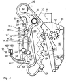
- Fig. 1 shows a first embodiment of an arrangement for the construction of two tobacco strands in a cigarette rod machine, wherein the schematic representation of the arrangement for the invention comprises essential elements of a tobacco distributor.
- tobacco is fed to a pre-distributor 10, which is provided with the raking rollers 12 and 13.
- the pre-distributor 10 opens into a tobacco reservoir 16, the discharge side is associated with a steep conveyor 17, which cooperates with a tobacco combing paddle roller 18 and with a tobacco in a downwardly leading feed chute 19 separating singling roller 21.
- the feed chute 19 is bounded by a boundary plate 20.
- the feed chute 19 opens laterally into a section of a viewing means in the form of a vertically arranged zig-zag separator 22.
- the zig-zag sifter 22 is part of a circulating air blower 23 operated air circulation system 24.
- a Um povertykrümmer is provided in the region of its outer radius in a bypass branching off from the air circulation system 24 and in the area its inner radius merges into an excess flow channel, in which a tobacco excess transport means in the form of a screw conveyor and a cellular wheel opens.
- recirculation system 24 of the classifier circuit also designed as a Coanda separator tobacco / air separator 26 is connected on both sides of a Abscheidekante 36 on the one hand to the suction side of the crossflow fan 23, and on the other hand in a above two storage bays 40, 40 'arranged rotary valve 37th opens.
- an impeller 38 is still provided for dispensing the tobacco and a feed element 39, by means of which alternately the two storage spaces 40, 40' can be filled with tobacco.
- the rotary valve 37 is used to separate transport air from the air circulation system 24 from Tobacco, which is promoted by the Tabakabscheideraum 81 above the rotary valve 37 to this.
- a guide channel which is delimited by a guide surface, which merges into a respective one-lane flow surface 44, 44' of a flow channel.
- the flow channels are initially superimposed.
- blown air feeds 43, 43 ' By means of blown air feeds 43, 43 ', a tight-fitting, tobacco-conveying air flow is generated at the flow surfaces 44, 44'.
- the upwardly leading flow surfaces 44, 44 ' open below a strand assembly unit of a double-strand machine, wherein in Fig. 1 schematically two Saugstrang considerer 50, 50 'are shown.
- the Saugstrang considerer are according to the DE 36 19 579 C2 built up.
- the upwardly aspirating tobacco infill flows pass accordingly Fig. 1 to two suction belt conveyors 50, 50 'arranged parallel to one another, each of which consists of an air-permeable conveyor belt running along a bottom of a perforated plate, the rear side of which is under the suction effect of a vacuum chamber.
- the excess transport air is sucked by means of Lucasabsaugelementen 30, 30 '.
- the transport air itself is brought by means of a schematically indicated air flow 43 or 43 'in the direction of the flow surfaces 44 and 44'.
- the tobacco / air separator 26 is arranged around a tubular body 48.
- the zig-zag sifter 22 is equipped with a screw 47, with which the separated preparegut, such as tobacco ribs, is removed.
- the separated preparegut such as tobacco ribs
- Tobacco passes through the feed lock 11 and the predistributor 10 into the tobacco reservoir 16 to the steep conveyor 17, from which the classifier system is charged with a continuous stream of tobacco by combing tobacco from the tobacco reservoir 16 with the steep conveyor 17 equipped with steep conveyor combs.
- excess tobacco is scraped off by the paddle roller 18.
- a machine stop may be initiated at a reduced speed, e.g. To prevent damage by foreign bodies.
- the tobacco lying on the steep conveyor 17 enters the area of action of the separating roller 21, which accelerates the tobacco into the zig-zag classifier 22 by rough pre-singling and whose speed is set with regard to optimum minimum tobacco fiber degradation and maximum singulation, preferably in FIG a range between 800 and 900 revolutions per minute.
- the precipitated from the zig-zag sifter 22 ribbed material can be blown by a Nachsichter using branched off from the air circulation sifting air, which are still transported back to the ribs lighter tobacco particles are transported back into the main air flow.
- the tobacco ribs are then discharged by means of a lock in a known manner, with this particular on the DE 101 54 807.9 is referenced.
- the sighted tobacco stream passes into the tobacco / air separator 26, in which the separation of tobacco and air by the centrifugal force and the Coanda effect, the tobacco fibers moved by the centrifugal force on the outer geometry in the form of a curved outer side of the separator 26 along are due to the Coanda effect on the inner radius of the geometry in the form of a cylindrical surface of a tubular body 48 applies.
- the separation edge 36 the final separation of air and tobacco takes place, the air separated from the tobacco is fed back to the crossflow fan 23, which has a uniform flow profile or over the width (perpendicular to the plane) of the distributor a homogeneous velocity distribution.
- the tobacco separated in the tobacco / air separator 26 is discharged from the vision system by the rotary valve 37 and arrives via an impeller 38 for discharging the quantities of tobacco to two storage spaces 40, 40 ', wherein in the in Fig. 1 illustrated position of the feed element 39, the tobacco fibers in the in Fig. 1 right lying stowage 40 'is promoted. In the position of the feed element 39 shown in dashed lines, tobacco enters the stowage chamber 40 shown on the left. In the arrangement itself, the stowage compartments 40 and 40 'are arranged one behind the other and extend over the entire width of the arrangement, which is perpendicular to the plane of the drawing.
- the storage ducts overlap only in a partial area (seen transversely to the conveying direction 91) and not over the entire (distributor) width, which has the advantage of a shorter overall length with still good delivery of tobacco fibers to the Saugstrangzierer.
- Respective Blas Kunststoffzu exchangeen are represented by the characters 43 and 43 ', with additional Blas Kunststoffzu operationen, such as.
- the DE 101 54 807.9 or the EP 1 174 046 A2 can be used very well to achieve excellent separation of tobacco fibers.
- control units are also provided for setting and maintaining optimum flow conditions and pressure conditions, in particular in Fig. 1 Beerabsaugiata 30, 30 'just before the Saugstrang makeupern 50, 50' are arranged to be able to suck off excess air can.
- the Saustrangierer promote tobacco, which itself is not shown, in the conveying direction 91, ie in the plane of the Fig. 1 to 4 into it.
- the feed means 39 as flaps 71 and 71 'are formed.
- the flaps 71, 71 'are pivotally mounted in the chute 70 and extend into the plane of the drawing across the width of the chutes 40, 40'.
- the chute 70 engages over the two flaps 71, 71 ', which is not absolutely necessary for their operation and function.
- the pivot shafts 34.1, 34.1 ' are preferably tubular and thus have sufficient rigidity and buckling strength despite their relatively large length and relatively small diameter. As a result, the rapid changes between the respective filling positions of the flaps 71, 71 'and the associated dynamic loads permanently withstand and any critical vibration behavior can be avoided.
- the respective storage chutes 40, 40 ' are each assigned to fill level control means extending vertically and horizontally across the width and at least a partial height of the storage chutes 40, 40'.
- the level control means are light barriers 32, 33, 32 ', 33'.
- the light barriers 32, 33, 32 ', 33' are signal output side connected via lines with a control unit, not shown.
- the control unit is the output side with the drive the steep conveyor 17 connected to the conveying speed and flow rate of tobacco fibers to change and regulate (as in the rest of Fig. 4 is shown with the line leading from the reference numeral 31 (logic unit) to a control unit (box)).
- the groups of light barriers 32, 33, 32 ', 33' can be designed as analog light strips.
- the residence time of the flaps 71, 71 'above or in front of the respective stowage bay 40, 40' is fixedly adjustable. It can be the same or different for the two storage chutes 40, 40 ', thus allowing a good adaptation to any operating state for a stranded product to be manufactured. For example, it is possible to leave the flaps 71, 71 'about 10% longer over one stowage 40, 40' than over the other stowage 40, 40 '. It is also possible, both storage spaces 40, 40 'at z. B. divergent flap position to fill at the same time, in particular - depending on flap position - with a different amount of fibers.
- the delivery rates of the respective unit from removal roller 42, 42 'and Ausschlagwalze 41, 41' and the ratio of the delivery rates to each other can be specified. If, for example, the ratio of the delivery rates of the two removal units is set to 45 to 55, then the residence time ratio of the flaps 71, 71 'above the respective delivery shaft 40, 40' is also predetermined and maintained.
- the higher-level machine control detects which stowage 40, 40 'is being filled. If the front stowage bay is being filled, then the light barriers 32, 33 of the front stowage bay are interrogated and a deviation from a predefinable level is interrogated. Depending on whether this level is then exceeded or fallen below, the steep conveyor 17 is then driven to deliver less or more tobacco fibers by this then changes its conveying speed. If just or after the other storage shaft 40, 40 'filled and queried by means of the photoelectric sensors 32', 33 '(with appropriate flap position), the scheme runs accordingly.
- the impeller 38 and / or the rotary valve 37 can be dispensed with and a direct supply of fibers to the chute 70 and / or the flaps 71, 71 'can be provided, as is the case in particular in the exemplary embodiment Fig. 4 is provided.
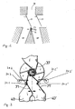
- the flaps 71, 71 'opposite end of the partition wall between the two storage compartments 40, 40' is provided with a tapered in section tipping element 72 which is arranged rotatably about a tilt axis 73.
- the tilting element 72 is formed approximately wedge-shaped in section and formed on its broad side with a rounding.
- the partition wall between the two storage spaces 40, 40 ' is provided with a corresponding cup-shaped recess, in which the rounding of the tilting element 72 is received to guide it in a tilting movement.
- fibers attach to the flap 71, 71 'facing the end of the partition wall between the two storage bays, they can be easily removed by a corresponding tilting, possibly by means of a drive, and one of the two storage bays 40th 40 '.
- the flap 71 ' With its end opposite the free end of a rotatably mounted pivot shaft 34.1' is added eccentrically to the axis of rotation.
- Each flap 71, 71 ' is provided with a corresponding mechanism, which are arranged in particular mirror-symmetrical to each other.
- the pivot shafts 34.1, 34.1 ' are in each case connected by means of a joint linkage 34.2, 34.2' with a servomotor 34.3, 34.3 'designed as adjusting and pivotable through this.
- a joint linkage 34.2, 34.2' with a servomotor 34.3, 34.3 'designed as adjusting and pivotable through this.
- the servomotors 34.3, 34.3 ' are connected to the machine control via lines and activated by means of appropriate control signals to pivot the flaps 71, 71' in the respectively desired position.
- crank drive in particular cyclically rotating or a toothed belt and / or rack / pinion drive can be provided.
- the flaps 71, 71 ' are so movable and each externally operable via the respective joint rods 34.2, 34.2' and the respective servomotors 34.3, 34.3 'arranged that the flaps 71, 71' both in a position to form a parallel channel as can also be brought into an at least temporary position for forming an at least converging and / or diverging channel.
- the angle enclosed between the flaps 71, 71 'during an adjustment of the flaps 71, 71' from a filling position for a first stowage 40, 40 'to a filling position for a second stowage 40, 40' is changeable, in particular reducible and / or enlargeable.
- the flaps 71, 71 ' are moved to each other with a time delay.
- first one (for example, inner) flap 71, 71 ' is moved, shortly thereafter the other (outer) flap 71, 71' receives its adjusting movement, whereby even faster changes are possible in a quasi-continuous manner, but always still a reliable and uniform filling is guaranteed. This leaves avoid a portionwise, jerky filling with time-delayed successive fiber portions.
- the two flaps 71, 71 ' during their pivoting from a first stowage bay 40, 40' to a second stowage bay 40, 40 ', preferably each have different speeds transverse to the direction of conveyance 91 of the at least one auger conveyor 50, 50', in particular with respect to it respective opposite their particular axis of rotation, in particular free end.
- a kind of temporary locking function during the change can be realized.
- Each or at least one flap 71, 71 ' has a lower velocity in the initial region of the pivoting path after the beginning and / or in the end region of the pivoting path before the end of its pivoting along the pivoting path, as in the range of about a quarter to about three quarters, preferably from about one-third to about two-thirds, more preferably about half, the pivoting distance.
- the respective beginning of the pivoting and the respective end of the pivoting can be gentle and gentle on the material, while quasi “on the move" adjustment takes place at maximum speed in order to reach the new position as quickly as possible.
- the ranges mentioned are preferred.
- the flaps 71, 71 ' are by means of the servo motors 34.3, 34.3' the joint rods 34.2, 34.2 'and the pivot shafts 34.1, 34.1' unevenly accelerated and / or unevenly delayed in bearings added.
- the flaps 71, 71 ' are provided with a fixed predetermined or variably adjustable dwell time over the respective storage shaft 40, 40' persisting. A control and / or regulation via the machine control.
- the flaps 71, 71 ' are each provided with a desired speed, acceleration, deceleration and / or a desired path-time curve back and forth pivotally.
- a wide variety of operating options is given, which, for example, also cleaning operations or troubleshooting, such as by a brief spreading of the flaps 71, 71 ', allow.
- As well as such a rapid movement that the flaps 71, 71 'trailing vortices are generated which allow a constant cleaning to the flaps 71, 71' of spaced components, such as on the partition wall of the two storage bays 40, 40 'deposited fibers, although these are outside a mechanical contact possibility.
- the flaps 71, 71 ' are each taken with their end opposite the free end of the respective rotatably mounted pivot shaft 34.1, 34.1' eccentrically to the respective axis of rotation.
- a central receptacle can also be provided.
- Fig. 4 shows a fourth embodiment of the arrangement according to the invention.
- This arrangement is a modification of the stowage arrangement according to the document EP 1 454 542 A1 , B1 or the publication IT BO20030125 , which is reproduced there in the single figure.
- the connecting means 26 of the two flaps 24z disclosed in the two aforementioned publications is removed and omitted, so that the flaps 24z are movable independently of each other.
Landscapes
- Manufacturing Of Cigar And Cigarette Tobacco (AREA)
Priority Applications (1)
| Application Number | Priority Date | Filing Date | Title |
|---|---|---|---|
| EP17000447.7A EP3375302B1 (fr) | 2017-03-17 | 2017-03-17 | Système et procédé de réalisation d'au moins deux faisceaux de fibres dans une machine de filage de l'industrie du tabac |
Applications Claiming Priority (1)
| Application Number | Priority Date | Filing Date | Title |
|---|---|---|---|
| EP17000447.7A EP3375302B1 (fr) | 2017-03-17 | 2017-03-17 | Système et procédé de réalisation d'au moins deux faisceaux de fibres dans une machine de filage de l'industrie du tabac |
Publications (2)
| Publication Number | Publication Date |
|---|---|
| EP3375302A1 true EP3375302A1 (fr) | 2018-09-19 |
| EP3375302B1 EP3375302B1 (fr) | 2019-09-25 |
Family
ID=58387583
Family Applications (1)
| Application Number | Title | Priority Date | Filing Date |
|---|---|---|---|
| EP17000447.7A Active EP3375302B1 (fr) | 2017-03-17 | 2017-03-17 | Système et procédé de réalisation d'au moins deux faisceaux de fibres dans une machine de filage de l'industrie du tabac |
Country Status (1)
| Country | Link |
|---|---|
| EP (1) | EP3375302B1 (fr) |
Citations (10)
| Publication number | Priority date | Publication date | Assignee | Title |
|---|---|---|---|---|
| DE2334727A1 (de) * | 1973-07-07 | 1975-02-13 | Quester Fa Wilh | Pneumatische zufuehrungsvorrichtung von fasergut wie tabak u. dgl |
| DE3330167A1 (de) | 1982-09-08 | 1984-03-08 | G.D S.p.A., 40100 Bologna | Fertigungsmaschine fuer die gleichzeitige herstellung von fortlaufenden zigarettenstraengen |
| DE3209195C2 (fr) | 1981-04-01 | 1990-07-19 | G.D S.P.A., Bologna, It | |
| DE3619579C2 (de) | 1986-06-11 | 1995-05-18 | Hauni Werke Koerber & Co Kg | Vorrichtung zur gleichzeitigen Herstellung von zwei Endloszigarettensträngen |
| EP1174046A2 (fr) | 2000-07-20 | 2002-01-23 | Hauni Maschinenbau AG | Procédé et dispositif pour séparer des fibres de tabac |
| DE10154807A1 (de) | 2001-08-16 | 2003-05-22 | Hauni Maschinenbau Ag | Anordnung zum Aufbau wenigstens eines Tabakstranges in einer Zigarettenstrangmaschine |
| EP1364588A1 (fr) | 2002-05-21 | 2003-11-26 | Hauni Maschinenbau AG | Dispositif et procédé pour la formation d'au moins deux tiges de tabac dans une machine de fabrication de tige de tabac |
| ITBO20030125A1 (it) | 2003-03-07 | 2004-09-08 | Gd Spa | Metodo ed unita` per la realizzazione contemporanea |
| EP1702521A1 (fr) | 2005-03-18 | 2006-09-20 | Hauni Maschinenbau AG | Contrôle de l'hauteur de retenu |
| EP2739168A1 (fr) * | 2011-08-02 | 2014-06-11 | International Tobacco Machinery Poland Sp. z o.o. | Unité de soupape pour le remplissage de conduits de transport angulaires avec le débit massique d'articles en forme de tiges |
-
2017
- 2017-03-17 EP EP17000447.7A patent/EP3375302B1/fr active Active
Patent Citations (12)
| Publication number | Priority date | Publication date | Assignee | Title |
|---|---|---|---|---|
| DE2334727A1 (de) * | 1973-07-07 | 1975-02-13 | Quester Fa Wilh | Pneumatische zufuehrungsvorrichtung von fasergut wie tabak u. dgl |
| DE3209195C2 (fr) | 1981-04-01 | 1990-07-19 | G.D S.P.A., Bologna, It | |
| DE3330167A1 (de) | 1982-09-08 | 1984-03-08 | G.D S.p.A., 40100 Bologna | Fertigungsmaschine fuer die gleichzeitige herstellung von fortlaufenden zigarettenstraengen |
| DE3619579C2 (de) | 1986-06-11 | 1995-05-18 | Hauni Werke Koerber & Co Kg | Vorrichtung zur gleichzeitigen Herstellung von zwei Endloszigarettensträngen |
| EP1174046A2 (fr) | 2000-07-20 | 2002-01-23 | Hauni Maschinenbau AG | Procédé et dispositif pour séparer des fibres de tabac |
| DE10154807A1 (de) | 2001-08-16 | 2003-05-22 | Hauni Maschinenbau Ag | Anordnung zum Aufbau wenigstens eines Tabakstranges in einer Zigarettenstrangmaschine |
| EP1364588A1 (fr) | 2002-05-21 | 2003-11-26 | Hauni Maschinenbau AG | Dispositif et procédé pour la formation d'au moins deux tiges de tabac dans une machine de fabrication de tige de tabac |
| ITBO20030125A1 (it) | 2003-03-07 | 2004-09-08 | Gd Spa | Metodo ed unita` per la realizzazione contemporanea |
| EP1454542A1 (fr) | 2003-03-07 | 2004-09-08 | G.D. Societa' per Azioni | Procédé et dispositif pour la production simulatnée de plusieurs boudins de tabac |
| EP1454542B1 (fr) | 2003-03-07 | 2005-12-07 | G.D Societ Per Azioni | Procédé et dispositif pour la production simulatnée de plusieurs boudins de tabac |
| EP1702521A1 (fr) | 2005-03-18 | 2006-09-20 | Hauni Maschinenbau AG | Contrôle de l'hauteur de retenu |
| EP2739168A1 (fr) * | 2011-08-02 | 2014-06-11 | International Tobacco Machinery Poland Sp. z o.o. | Unité de soupape pour le remplissage de conduits de transport angulaires avec le débit massique d'articles en forme de tiges |
Non-Patent Citations (1)
| Title |
|---|
| ERNST VOGUES: "Tobacco Encyclopedia", 1984, pages: 421 |
Also Published As
| Publication number | Publication date |
|---|---|
| EP3375302B1 (fr) | 2019-09-25 |
Similar Documents
| Publication | Publication Date | Title |
|---|---|---|
| EP1364588B1 (fr) | Dispositif et procédé pour la formation d'au moins deux tiges de tabac dans une machine de fabrication de tige de tabac | |
| EP1285592B1 (fr) | Dispositif de formation d'une tige de tabac dans une machine de fabrication de tige de tabac | |
| DE112019004566B4 (de) | System zum Zuführen eines granulierten Materials und dabei verwendetes Zuführverfahren | |
| EP2995183B1 (fr) | Dispositif de dosage | |
| EP1952706A1 (fr) | Magasin de vidage et procédé de vidage de récipients remplis de produits en forme de tige, en particulier récipients en forme de colonne | |
| EP2369949A1 (fr) | Équipement et procédé d'amenée de tabac haché entre une unité de chargement du tabac et une machine de transformation du tabac | |
| EP2120615B1 (fr) | Magasin de vidage pour un dispositif de vidage de conteneur conçu pour vider des conteneurs remplis de produits en forme de tige | |
| EP2220950B1 (fr) | Cartouche de vidage et procédé de vidage de combles remplis de produits en forme de tiges, notamment combles de puits | |
| DE3114188C2 (fr) | ||
| DE3209195A1 (de) | Kontinuierlich arbeitende zweistrang-zigaretten-fertigungsmaschine | |
| EP3208001B1 (fr) | Séparateur pneumatique doté d'une triple séparation | |
| DE10035692A1 (de) | Verfahren und Vorrichtung zum Vereinzeln von Tabakfasern | |
| DE4136498C2 (de) | Einrichtung zur gerichteten Zufuhr von Tabakrippen zu einem Schneidegerät | |
| DE3937151A1 (de) | Beschickungsvorrichtung fuer eine doppelstrangmaschine der tabakverarbeitenden industrie | |
| EP1825767B1 (fr) | Corps d'écoulement d'une machine à rouler des cigarettes | |
| AT506149B1 (de) | Fördervorrichtung für kleinteile | |
| EP3375302B1 (fr) | Système et procédé de réalisation d'au moins deux faisceaux de fibres dans une machine de filage de l'industrie du tabac | |
| EP2721936A2 (fr) | Dispositif de distribution et procédé de garniture d'une machine à fabriquer des tiges de l'industrie de traitement du tabac avec un flux de produit constitué de matériau fibreux | |
| EP2952106B1 (fr) | Système de machines de l'industrie de traitement du tabac et procédé de guidage de matière fibreuse | |
| DE102011106167A1 (de) | Maschine und Verfahren zur Formung von Teilstücken aus Fasermaterial | |
| DE102007040173A1 (de) | Vorrichtung und Verfahren zum Zusammenführen von aus stabförmigen Artikeln gebildeten Massenströmen | |
| EP1529449A1 (fr) | Appareil pour séparer tabac et air, et dispositif et procédé pour la formation d'au moins deux tiges de tabac dans une machine de fabrication de tige de tabac | |
| EP3514085B1 (fr) | Unité de transport et d'alimentation pour préformés | |
| EP0682882A1 (fr) | Distributeur de tabac pour machines à fabriquer les cigarettes | |
| EP3135128A2 (fr) | Station de vidage de baquets destinée à vider des baquets remplis de produits en forme de tige et procédé pour vider des baquets remplis de produits en forme de tige à l'aide d'une station de vidage de baquets |
Legal Events
| Date | Code | Title | Description |
|---|---|---|---|
| PUAI | Public reference made under article 153(3) epc to a published international application that has entered the european phase |
Free format text: ORIGINAL CODE: 0009012 |
|
| STAA | Information on the status of an ep patent application or granted ep patent |
Free format text: STATUS: THE APPLICATION HAS BEEN PUBLISHED |
|
| STAA | Information on the status of an ep patent application or granted ep patent |
Free format text: STATUS: REQUEST FOR EXAMINATION WAS MADE |
|
| AK | Designated contracting states |
Kind code of ref document: A1 Designated state(s): AL AT BE BG CH CY CZ DE DK EE ES FI FR GB GR HR HU IE IS IT LI LT LU LV MC MK MT NL NO PL PT RO RS SE SI SK SM TR |
|
| AX | Request for extension of the european patent |
Extension state: BA ME |
|
| 17P | Request for examination filed |
Effective date: 20180904 |
|
| GRAP | Despatch of communication of intention to grant a patent |
Free format text: ORIGINAL CODE: EPIDOSNIGR1 |
|
| STAA | Information on the status of an ep patent application or granted ep patent |
Free format text: STATUS: GRANT OF PATENT IS INTENDED |
|
| INTG | Intention to grant announced |
Effective date: 20190603 |
|
| GRAS | Grant fee paid |
Free format text: ORIGINAL CODE: EPIDOSNIGR3 |
|
| GRAA | (expected) grant |
Free format text: ORIGINAL CODE: 0009210 |
|
| STAA | Information on the status of an ep patent application or granted ep patent |
Free format text: STATUS: THE PATENT HAS BEEN GRANTED |
|
| AK | Designated contracting states |
Kind code of ref document: B1 Designated state(s): AL AT BE BG CH CY CZ DE DK EE ES FI FR GB GR HR HU IE IS IT LI LT LU LV MC MK MT NL NO PL PT RO RS SE SI SK SM TR |
|
| REG | Reference to a national code |
Ref country code: GB Ref legal event code: FG4D Free format text: NOT ENGLISH |
|
| REG | Reference to a national code |
Ref country code: CH Ref legal event code: EP |
|
| REG | Reference to a national code |
Ref country code: AT Ref legal event code: REF Ref document number: 1182933 Country of ref document: AT Kind code of ref document: T Effective date: 20191015 |
|
| REG | Reference to a national code |
Ref country code: IE Ref legal event code: FG4D Free format text: LANGUAGE OF EP DOCUMENT: GERMAN |
|
| REG | Reference to a national code |
Ref country code: DE Ref legal event code: R096 Ref document number: 502017002357 Country of ref document: DE |
|
| REG | Reference to a national code |
Ref country code: NL Ref legal event code: MP Effective date: 20190925 |
|
| PG25 | Lapsed in a contracting state [announced via postgrant information from national office to epo] |
Ref country code: FI Free format text: LAPSE BECAUSE OF FAILURE TO SUBMIT A TRANSLATION OF THE DESCRIPTION OR TO PAY THE FEE WITHIN THE PRESCRIBED TIME-LIMIT Effective date: 20190925 Ref country code: NO Free format text: LAPSE BECAUSE OF FAILURE TO SUBMIT A TRANSLATION OF THE DESCRIPTION OR TO PAY THE FEE WITHIN THE PRESCRIBED TIME-LIMIT Effective date: 20191225 Ref country code: HR Free format text: LAPSE BECAUSE OF FAILURE TO SUBMIT A TRANSLATION OF THE DESCRIPTION OR TO PAY THE FEE WITHIN THE PRESCRIBED TIME-LIMIT Effective date: 20190925 Ref country code: BG Free format text: LAPSE BECAUSE OF FAILURE TO SUBMIT A TRANSLATION OF THE DESCRIPTION OR TO PAY THE FEE WITHIN THE PRESCRIBED TIME-LIMIT Effective date: 20191225 Ref country code: SE Free format text: LAPSE BECAUSE OF FAILURE TO SUBMIT A TRANSLATION OF THE DESCRIPTION OR TO PAY THE FEE WITHIN THE PRESCRIBED TIME-LIMIT Effective date: 20190925 Ref country code: LT Free format text: LAPSE BECAUSE OF FAILURE TO SUBMIT A TRANSLATION OF THE DESCRIPTION OR TO PAY THE FEE WITHIN THE PRESCRIBED TIME-LIMIT Effective date: 20190925 |
|
| REG | Reference to a national code |
Ref country code: LT Ref legal event code: MG4D |
|
| PG25 | Lapsed in a contracting state [announced via postgrant information from national office to epo] |
Ref country code: LV Free format text: LAPSE BECAUSE OF FAILURE TO SUBMIT A TRANSLATION OF THE DESCRIPTION OR TO PAY THE FEE WITHIN THE PRESCRIBED TIME-LIMIT Effective date: 20190925 Ref country code: GR Free format text: LAPSE BECAUSE OF FAILURE TO SUBMIT A TRANSLATION OF THE DESCRIPTION OR TO PAY THE FEE WITHIN THE PRESCRIBED TIME-LIMIT Effective date: 20191226 Ref country code: RS Free format text: LAPSE BECAUSE OF FAILURE TO SUBMIT A TRANSLATION OF THE DESCRIPTION OR TO PAY THE FEE WITHIN THE PRESCRIBED TIME-LIMIT Effective date: 20190925 |
|
| PG25 | Lapsed in a contracting state [announced via postgrant information from national office to epo] |
Ref country code: RO Free format text: LAPSE BECAUSE OF FAILURE TO SUBMIT A TRANSLATION OF THE DESCRIPTION OR TO PAY THE FEE WITHIN THE PRESCRIBED TIME-LIMIT Effective date: 20190925 Ref country code: PL Free format text: LAPSE BECAUSE OF FAILURE TO SUBMIT A TRANSLATION OF THE DESCRIPTION OR TO PAY THE FEE WITHIN THE PRESCRIBED TIME-LIMIT Effective date: 20190925 Ref country code: PT Free format text: LAPSE BECAUSE OF FAILURE TO SUBMIT A TRANSLATION OF THE DESCRIPTION OR TO PAY THE FEE WITHIN THE PRESCRIBED TIME-LIMIT Effective date: 20200127 Ref country code: ES Free format text: LAPSE BECAUSE OF FAILURE TO SUBMIT A TRANSLATION OF THE DESCRIPTION OR TO PAY THE FEE WITHIN THE PRESCRIBED TIME-LIMIT Effective date: 20190925 Ref country code: AL Free format text: LAPSE BECAUSE OF FAILURE TO SUBMIT A TRANSLATION OF THE DESCRIPTION OR TO PAY THE FEE WITHIN THE PRESCRIBED TIME-LIMIT Effective date: 20190925 Ref country code: NL Free format text: LAPSE BECAUSE OF FAILURE TO SUBMIT A TRANSLATION OF THE DESCRIPTION OR TO PAY THE FEE WITHIN THE PRESCRIBED TIME-LIMIT Effective date: 20190925 Ref country code: EE Free format text: LAPSE BECAUSE OF FAILURE TO SUBMIT A TRANSLATION OF THE DESCRIPTION OR TO PAY THE FEE WITHIN THE PRESCRIBED TIME-LIMIT Effective date: 20190925 |
|
| PG25 | Lapsed in a contracting state [announced via postgrant information from national office to epo] |
Ref country code: CZ Free format text: LAPSE BECAUSE OF FAILURE TO SUBMIT A TRANSLATION OF THE DESCRIPTION OR TO PAY THE FEE WITHIN THE PRESCRIBED TIME-LIMIT Effective date: 20190925 Ref country code: SM Free format text: LAPSE BECAUSE OF FAILURE TO SUBMIT A TRANSLATION OF THE DESCRIPTION OR TO PAY THE FEE WITHIN THE PRESCRIBED TIME-LIMIT Effective date: 20190925 Ref country code: IS Free format text: LAPSE BECAUSE OF FAILURE TO SUBMIT A TRANSLATION OF THE DESCRIPTION OR TO PAY THE FEE WITHIN THE PRESCRIBED TIME-LIMIT Effective date: 20200224 Ref country code: SK Free format text: LAPSE BECAUSE OF FAILURE TO SUBMIT A TRANSLATION OF THE DESCRIPTION OR TO PAY THE FEE WITHIN THE PRESCRIBED TIME-LIMIT Effective date: 20190925 |
|
| REG | Reference to a national code |
Ref country code: DE Ref legal event code: R097 Ref document number: 502017002357 Country of ref document: DE |
|
| PG2D | Information on lapse in contracting state deleted |
Ref country code: IS |
|
| PG25 | Lapsed in a contracting state [announced via postgrant information from national office to epo] |
Ref country code: DK Free format text: LAPSE BECAUSE OF FAILURE TO SUBMIT A TRANSLATION OF THE DESCRIPTION OR TO PAY THE FEE WITHIN THE PRESCRIBED TIME-LIMIT Effective date: 20190925 Ref country code: IS Free format text: LAPSE BECAUSE OF FAILURE TO SUBMIT A TRANSLATION OF THE DESCRIPTION OR TO PAY THE FEE WITHIN THE PRESCRIBED TIME-LIMIT Effective date: 20200126 |
|
| PLBE | No opposition filed within time limit |
Free format text: ORIGINAL CODE: 0009261 |
|
| STAA | Information on the status of an ep patent application or granted ep patent |
Free format text: STATUS: NO OPPOSITION FILED WITHIN TIME LIMIT |
|
| 26N | No opposition filed |
Effective date: 20200626 |
|
| PG25 | Lapsed in a contracting state [announced via postgrant information from national office to epo] |
Ref country code: MC Free format text: LAPSE BECAUSE OF FAILURE TO SUBMIT A TRANSLATION OF THE DESCRIPTION OR TO PAY THE FEE WITHIN THE PRESCRIBED TIME-LIMIT Effective date: 20190925 |
|
| REG | Reference to a national code |
Ref country code: CH Ref legal event code: PL |
|
| PG25 | Lapsed in a contracting state [announced via postgrant information from national office to epo] |
Ref country code: SI Free format text: LAPSE BECAUSE OF FAILURE TO SUBMIT A TRANSLATION OF THE DESCRIPTION OR TO PAY THE FEE WITHIN THE PRESCRIBED TIME-LIMIT Effective date: 20190925 |
|
| REG | Reference to a national code |
Ref country code: BE Ref legal event code: MM Effective date: 20200331 |
|
| PG25 | Lapsed in a contracting state [announced via postgrant information from national office to epo] |
Ref country code: LU Free format text: LAPSE BECAUSE OF NON-PAYMENT OF DUE FEES Effective date: 20200317 |
|
| PG25 | Lapsed in a contracting state [announced via postgrant information from national office to epo] |
Ref country code: LI Free format text: LAPSE BECAUSE OF NON-PAYMENT OF DUE FEES Effective date: 20200331 Ref country code: IE Free format text: LAPSE BECAUSE OF NON-PAYMENT OF DUE FEES Effective date: 20200317 Ref country code: CH Free format text: LAPSE BECAUSE OF NON-PAYMENT OF DUE FEES Effective date: 20200331 Ref country code: FR Free format text: LAPSE BECAUSE OF NON-PAYMENT OF DUE FEES Effective date: 20200331 |
|
| PG25 | Lapsed in a contracting state [announced via postgrant information from national office to epo] |
Ref country code: BE Free format text: LAPSE BECAUSE OF NON-PAYMENT OF DUE FEES Effective date: 20200331 |
|
| GBPC | Gb: european patent ceased through non-payment of renewal fee |
Effective date: 20210317 |
|
| PG25 | Lapsed in a contracting state [announced via postgrant information from national office to epo] |
Ref country code: GB Free format text: LAPSE BECAUSE OF NON-PAYMENT OF DUE FEES Effective date: 20210317 |
|
| PG25 | Lapsed in a contracting state [announced via postgrant information from national office to epo] |
Ref country code: TR Free format text: LAPSE BECAUSE OF FAILURE TO SUBMIT A TRANSLATION OF THE DESCRIPTION OR TO PAY THE FEE WITHIN THE PRESCRIBED TIME-LIMIT Effective date: 20190925 Ref country code: MT Free format text: LAPSE BECAUSE OF FAILURE TO SUBMIT A TRANSLATION OF THE DESCRIPTION OR TO PAY THE FEE WITHIN THE PRESCRIBED TIME-LIMIT Effective date: 20190925 Ref country code: CY Free format text: LAPSE BECAUSE OF FAILURE TO SUBMIT A TRANSLATION OF THE DESCRIPTION OR TO PAY THE FEE WITHIN THE PRESCRIBED TIME-LIMIT Effective date: 20190925 |
|
| PG25 | Lapsed in a contracting state [announced via postgrant information from national office to epo] |
Ref country code: MK Free format text: LAPSE BECAUSE OF FAILURE TO SUBMIT A TRANSLATION OF THE DESCRIPTION OR TO PAY THE FEE WITHIN THE PRESCRIBED TIME-LIMIT Effective date: 20190925 |
|
| REG | Reference to a national code |
Ref country code: DE Ref legal event code: R081 Ref document number: 502017002357 Country of ref document: DE Owner name: KOERBER TECHNOLOGIES GMBH, DE Free format text: FORMER OWNER: HAUNI MASCHINENBAU GMBH, 21033 HAMBURG, DE |
|
| REG | Reference to a national code |
Ref country code: AT Ref legal event code: MM01 Ref document number: 1182933 Country of ref document: AT Kind code of ref document: T Effective date: 20220317 |
|
| P01 | Opt-out of the competence of the unified patent court (upc) registered |
Effective date: 20230621 |
|
| PG25 | Lapsed in a contracting state [announced via postgrant information from national office to epo] |
Ref country code: AT Free format text: LAPSE BECAUSE OF NON-PAYMENT OF DUE FEES Effective date: 20220317 |
|
| PGFP | Annual fee paid to national office [announced via postgrant information from national office to epo] |
Ref country code: DE Payment date: 20250331 Year of fee payment: 9 |
|
| PGFP | Annual fee paid to national office [announced via postgrant information from national office to epo] |
Ref country code: IT Payment date: 20250327 Year of fee payment: 9 |