EP3375368B1 - Verfahren und vorrichtung zur schätzung der atemfrequenz - Google Patents
Verfahren und vorrichtung zur schätzung der atemfrequenz Download PDFInfo
- Publication number
- EP3375368B1 EP3375368B1 EP16864128.0A EP16864128A EP3375368B1 EP 3375368 B1 EP3375368 B1 EP 3375368B1 EP 16864128 A EP16864128 A EP 16864128A EP 3375368 B1 EP3375368 B1 EP 3375368B1
- Authority
- EP
- European Patent Office
- Prior art keywords
- frequency
- interval
- time
- respiration
- series signal
- Prior art date
- Legal status (The legal status is an assumption and is not a legal conclusion. Google has not performed a legal analysis and makes no representation as to the accuracy of the status listed.)
- Active
Links
Images




Classifications
-
- A—HUMAN NECESSITIES
- A61—MEDICAL OR VETERINARY SCIENCE; HYGIENE
- A61B—DIAGNOSIS; SURGERY; IDENTIFICATION
- A61B5/00—Measuring for diagnostic purposes; Identification of persons
- A61B5/24—Detecting, measuring or recording bioelectric or biomagnetic signals of the body or parts thereof
- A61B5/316—Modalities, i.e. specific diagnostic methods
- A61B5/318—Heart-related electrical modalities, e.g. electrocardiography [ECG]
- A61B5/346—Analysis of electrocardiograms
- A61B5/349—Detecting specific parameters of the electrocardiograph cycle
- A61B5/352—Detecting R peaks, e.g. for synchronising diagnostic apparatus; Estimating R-R interval
-
- A—HUMAN NECESSITIES
- A61—MEDICAL OR VETERINARY SCIENCE; HYGIENE
- A61B—DIAGNOSIS; SURGERY; IDENTIFICATION
- A61B5/00—Measuring for diagnostic purposes; Identification of persons
- A61B5/08—Measuring devices for evaluating the respiratory organs
- A61B5/0816—Measuring devices for examining respiratory frequency
-
- A—HUMAN NECESSITIES
- A61—MEDICAL OR VETERINARY SCIENCE; HYGIENE
- A61B—DIAGNOSIS; SURGERY; IDENTIFICATION
- A61B5/00—Measuring for diagnostic purposes; Identification of persons
- A61B5/103—Measuring devices for testing the shape, pattern, colour, size or movement of the body or parts thereof, for diagnostic purposes
- A61B5/11—Measuring movement of the entire body or parts thereof, e.g. head or hand tremor or mobility of a limb
- A61B5/113—Measuring movement of the entire body or parts thereof, e.g. head or hand tremor or mobility of a limb occurring during breathing
-
- A—HUMAN NECESSITIES
- A61—MEDICAL OR VETERINARY SCIENCE; HYGIENE
- A61B—DIAGNOSIS; SURGERY; IDENTIFICATION
- A61B5/00—Measuring for diagnostic purposes; Identification of persons
- A61B5/24—Detecting, measuring or recording bioelectric or biomagnetic signals of the body or parts thereof
- A61B5/316—Modalities, i.e. specific diagnostic methods
- A61B5/318—Heart-related electrical modalities, e.g. electrocardiography [ECG]
- A61B5/346—Analysis of electrocardiograms
-
- A—HUMAN NECESSITIES
- A61—MEDICAL OR VETERINARY SCIENCE; HYGIENE
- A61B—DIAGNOSIS; SURGERY; IDENTIFICATION
- A61B5/00—Measuring for diagnostic purposes; Identification of persons
- A61B5/24—Detecting, measuring or recording bioelectric or biomagnetic signals of the body or parts thereof
- A61B5/316—Modalities, i.e. specific diagnostic methods
- A61B5/318—Heart-related electrical modalities, e.g. electrocardiography [ECG]
- A61B5/346—Analysis of electrocardiograms
- A61B5/347—Detecting the frequency distribution of signals
-
- A—HUMAN NECESSITIES
- A61—MEDICAL OR VETERINARY SCIENCE; HYGIENE
- A61B—DIAGNOSIS; SURGERY; IDENTIFICATION
- A61B5/00—Measuring for diagnostic purposes; Identification of persons
- A61B5/72—Signal processing specially adapted for physiological signals or for diagnostic purposes
- A61B5/7221—Determining signal validity, reliability or quality
-
- A—HUMAN NECESSITIES
- A61—MEDICAL OR VETERINARY SCIENCE; HYGIENE
- A61B—DIAGNOSIS; SURGERY; IDENTIFICATION
- A61B5/00—Measuring for diagnostic purposes; Identification of persons
- A61B5/72—Signal processing specially adapted for physiological signals or for diagnostic purposes
- A61B5/7235—Details of waveform analysis
- A61B5/7253—Details of waveform analysis characterised by using transforms
- A61B5/7257—Details of waveform analysis characterised by using transforms using Fourier transforms
-
- A—HUMAN NECESSITIES
- A61—MEDICAL OR VETERINARY SCIENCE; HYGIENE
- A61B—DIAGNOSIS; SURGERY; IDENTIFICATION
- A61B5/00—Measuring for diagnostic purposes; Identification of persons
- A61B5/72—Signal processing specially adapted for physiological signals or for diagnostic purposes
- A61B5/7271—Specific aspects of physiological measurement analysis
- A61B5/7278—Artificial waveform generation or derivation, e.g. synthesizing signals from measured signals
-
- A—HUMAN NECESSITIES
- A61—MEDICAL OR VETERINARY SCIENCE; HYGIENE
- A61B—DIAGNOSIS; SURGERY; IDENTIFICATION
- A61B5/00—Measuring for diagnostic purposes; Identification of persons
- A61B5/68—Arrangements of detecting, measuring or recording means, e.g. sensors, in relation to patient
- A61B5/6801—Arrangements of detecting, measuring or recording means, e.g. sensors, in relation to patient specially adapted to be attached to or worn on the body surface
- A61B5/6802—Sensor mounted on worn items
- A61B5/6804—Garments; Clothes
Definitions
- the present invention relates to a respiration estimation method and apparatus for estimating the respiration condition of a subject using a biological information sensor.
- Continuous respiratory monitoring of continuously observing breathing of a person is expected to be applied to diagnosis of respiratory diseases, the rehabilitation of a patient with a respiratory disease, remote monitoring of a fetus or patient, stress diagnosis, and the like.
- a respiratory flow meter by a mask heat measurement by a thermistor arranged in the nasal cavity, a chest deflection measurement band, an electrical impedance meter for a chest, or the like is used. These methods pose a problem that a subject has an unnatural feeling when wearing the device.
- a wearable sensor in which electrodes 101 and 102 are embedded in clothing 100 such as a shirt, as shown in Fig. 8 (patent literature 1).
- This wearable sensor functions as a wearable electrocardiograph by arranging, near a heart 103, the electrodes 101 and 102 made of conductive fiber, and connecting the electrodes 101 and 102 to terminals (not shown) via wiring lines.
- a measurement error occurs in accordance with a change in contact impedance between the electrode and the skin, that is caused by the body motion or skin condition of the subject, or the individual difference of the body structure or skin condition of the subject.
- non-patent literature 1 discloses a method of estimating the respiration condition (breathing rate) of a subject based on acceleration data of the subject in addition to conventional electrocardiograph data.
- the method disclosed in non-patent literature 1 improves estimation accuracy by obtaining the weighted mean of three indices of the R-R interval, R-wave amplitude, and acceleration of a cardiac potential.
- the weighting constants Q RSA , Q QRSa , and Q accel of equation (1) change depending on the respective indices of the R-R interval, R-wave amplitude, and acceleration, and are adjusted within the range of 0 to 1 depending on the signal quality.
- an error constant E is calculated as the linear sum of four parameters, that is, the standard deviation of peak amplitudes, the average value of the peak amplitudes, a time-varying constant between minimum values, and the ratio between the number of maximum and minimum values and the total number of maximum and minimum values, and signal quality Q is given by: where ⁇ represents an empirically determined constant. Note that if the signal amplitude is set as a noise level, Q is set to zero.
- a respiratory rate measurement using a combination of respiration signals is known from US 2014/228692 A1 and WO 2013/033393 A1 . Both documents describe an R-wave amplitude detection and an R-R interval detection from a cardiac potential waveform and an acceleration displacement detection from an acceleration signal by a respiration motion of the subject.
- the method and system allow for measuring a respiratory rate using a combination of respiration signals.
- a quality metric is computed for each of the respiration signals and the resulting metrics are combined to compute a weighted respiratory rate.
- US 2010/004552 A1 discloses a method and device for the determination of breath frequency.
- the respiratory rate is determined on the basis of a combination of signals made either in the time domain or in the frequency domain.
- Patent Literature 1 Japanese Patent Laid-Open No. 2015-83045
- Non-Patent Literature 1 A.M. Chan, N. Ferdosi, and R. Narasimhan, "Ambulatory Respiratory Rate Detection using ECG and a Triaxial Accelerometer", 35th Annual International Conference of the IEEE EMBS, pp. 4058-4061, July, 2013
- the present invention has been made in consideration of the above problems, and has as its object to provide a respiration estimation method and apparatus capable of improving respiration estimation accuracy under various conditions.
- respiration estimation apparatus as defined in the independent claim 5.
- the present invention by extracting a frequency as a candidate of the respiration frequency of a subject from each of the frequency spectrum of an R-wave amplitude, that of an R-R interval, and that of an angular displacement, and selecting the best data from the frequencies as the respiration frequency of the subject, it is possible to estimate the respiration frequency of the subject with respect to the individual difference or a wide variety of measurement conditions, and reduce the influence of the artifact of the body motion of the subject, thereby improving respiration estimation accuracy.
- Fig. 1 is a block diagram showing the arrangement of a respiration estimation apparatus according to the embodiment of the present invention.
- the respiration estimation apparatus includes an electrocardiograph 1, a triaxial accelerometer 2, storage units 3 and 4, an R-wave amplitude detection unit 5, an R-R interval detection unit 6, an acceleration displacement detection unit 7, a sampling unit 8, a bandpass filter 9, a Fourier transform unit 10, and a signal selection unit 11.
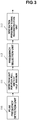
- Fig. 2 is a flowchart for explaining the operation of the respiration estimation apparatus.
- the electrocardiograph 1 measures the cardiac potential waveform of a subject, and outputs the time-series signal string of the cardiac potential waveform (step S100 of Fig. 2 ).
- the storage unit 3 stores the time-series signal string of the cardiac potential waveform output from the electrocardiograph 1.
- the cardiac potential waveform is formed from continuous heartbeat waveforms, and one heartbeat waveform is formed from components such as P, Q, R, S, and T waves reflecting the activities of atriums and ventricles.
- the R-wave amplitude detection unit 5 detects the amplitude of the R wave from the signals of the cardiac potential waveform stored in the storage unit 3 (step S101 of Fig. 2 ).
- a method of recognizing the R wave of the cardiac potential waveform there is provided, for example, a technique disclosed in Japanese Patent Laid-Open No. 2003-561 . This technique recognizes an R wave using a threshold based on an amplitude between the peak and valley of the cardiac potential waveform.
- the R-wave amplitude detection unit 5 detects an amplitude for each R wave of the cardiac potential waveform.
- the R-R interval detection unit 6 detects an R-R interval from the signals of the cardiac potential waveform stored in the storage unit 3 (step S102 of Fig. 2 ).
- a technique of detecting the R-R interval of the cardiac potential waveform for example, there is provided a technique disclosed in " ECG Implementation on the TMS320C5515 DSP Medical Development Kit (MDK) with the ADS1298 ECG-FE", Texas Instruments Incorporated, ⁇ http://www.ti.com/lit/an/sprabj1/sprabj1.pdf>, 2011 . This technique obtains an R-R interval based on a change in value of the time difference of the cardiac potential waveform.
- the R-R interval detection unit 6 detects an R-R interval for each R wave of the cardiac potential waveform.
- the triaxial accelerometer 2 is mounted on the chest of the subject, and detects a triaxial acceleration by the respiratory motion of the subject and outputs the time-series signal string of the triaxial acceleration (step S103 of Fig. 2 ).
- the storage unit 4 stores the time-series signal string of the triaxial acceleration output from the triaxial accelerometer 2.
- the acceleration displacement detection unit 7 detects the angular displacement of an acceleration vector from the signals of the triaxial acceleration stored in the storage unit 4 (step S104 of Fig. 2 ). To detect the angular displacement, after defining an acceleration variation surface from the average of the acceleration displacements in three axial directions, that is, the X, Y, and Z directions, the angle of a projection vector obtained when an acceleration vector formed from a combination of the acceleration data of the three axes in the X, Y, and Z directions is projected on the variation surface is calculated as the angular displacement. This method is disclosed in, for example, A. Bates, M.J. Ling, J. Mann and D.K. Arvind, "Respiratory rate and flow waveform estimation from triaxial accelerometer data", International Conference on Body Sensor Network, pp. 144-150, June 2010 . The acceleration displacement detection unit 7 detects an angular displacement for each sampling period of the acceleration.
- the sampling unit 8 samples each of the time-series signal of the R-wave amplitude output from the R-wave amplitude detection unit 5, the time-series signal of the R-R interval output from the R-R interval detection unit 6, and the time-series signal of the angular displacement output from the acceleration displacement detection unit 7 at a sampling frequency (for example, a 1-Hz interval) lower than the sampling frequency of the electrocardiograph 1 and that of the triaxial accelerometer 2 (step S105 of Fig. 2 ).
- a sampling frequency for example, a 1-Hz interval
- the bandpass filter 9 limits the band of each of the time-series signal of the R-wave amplitude, that of the R-R interval, and that of the angular displacement, all of which have been acquired by the sampling unit 8 (step S106 of Fig. 2 ).
- the reason why the bandpass filter 9 is used is that the respiration frequency of a person is limited to only a low frequency.
- the pass band of the bandpass filter 9 is, for example, 0.15 to 0.4 Hz.
- the Fourier transform unit 10 After multiplying, by a Hamming window function, each of the time-series signal of the R-wave amplitude, that of the R-R interval, and that of the angular displacement, whose band has been limited by the bandpass filter 9, the Fourier transform unit 10 performs fast Fourier transform for each of the time-series signal of the R-wave amplitude, that of the R-R interval, and that of the angular displacement, thereby obtaining the frequency spectrum of each of the signals of the R-wave amplitude, the R-R interval, and the angular displacement (step S107 of Fig. 2 ).
- the Hamming window function is used to cut desired input data.
- the Fourier transform unit 10 performs such Fourier transform for each sampling period of the sampling unit 8.
- the number of data used for Fourier transform is, for example, 128 points (128 sec).
- the signal selection unit 11 extracts a frequency as a candidate of the respiration frequency of the subject from each of the frequency spectrum of the R-wave amplitude, that of the R-R interval, and that of the angular displacement, all of which have been obtained by the Fourier transform unit 10, and selects the best data from the frequencies as the respiration frequency of the subject, thereby outputting a respiration frequency signal (step S108 of Fig. 2 ).
- Fig. 3 is a block diagram showing the arrangement of the signal selection unit 11.
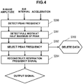
- Fig. 4 is a flowchart for explaining the operation of the signal selection unit 11.
- the signal selection unit 11 includes a peak frequency detection unit 110, a detection unit 111 for a peak full width at half maximum, a frequency selection unit 112, and a respiration frequency signal reconstruction unit 113.
- the peak frequency detection unit 110 detects a peak frequency of each of the frequency spectrum of the R-wave amplitude, that of the R-R interval, and that of the angular displacement, all of which have been obtained by the Fourier transform unit 10 (step S200 of Fig. 4 ). When a plurality of peaks are detected for one frequency spectrum, the peak frequency detection unit 110 selects the frequency of the peak whose intensity is the maximum.
- the detection unit 111 detects the full width at half maximum of the peak detected by the peak frequency detection unit 110 for each of the frequency spectrum of the R-wave amplitude, that of the R-R interval, and that of the angular displacement (step S201 of Fig. 4 ).
- the full width at half maximum indicates the width of the frequency at which the intensity is 50% of the peak intensity in the waveform of the peak detected by the peak frequency detection unit 110.
- Fig. 5A shows an example of the frequency spectrum when the SN ratio is high
- Fig. 5B shows an example of the frequency spectrum when the SN ratio is low
- Figs. 5A and 5B are graphs obtained by normalizing the intensity on the ordinate.
- normalization is performed by obtaining an area by integrating the power of each frequency (accumulating discrete values) so that the area of the power spectrum is 1.
- the power spectrum is obtained by cutting, for example, a section of 30 sec from the measured time-series data, and performing Fourier transform.
- the breathing rate fluctuates but stays constant while it is stable, and has a peak P at a given frequency.
- the peak P of the respiration frequency is normally considered to fall within the range of about 0.2 to 0.4 Hz.
- a full width W at half maximum of the peak tends to extend due to the influence of the body motion and autonomic nervous system of the subject. It is considered that as the full width W at half maximum is narrower, the respiration detection accuracy is higher.
- the frequency selection unit 112 selects, as the respiration frequency of the subject, the peak frequency at which the full width at half maximum detected by the detection unit 111 is equal to or smaller than a predetermined threshold (for example, 0.0625 Hz) among the three peak frequencies (the peak frequency of the R-wave amplitude, that of the R-R interval, and that of the angular displacement) detected by the peak frequency detection unit 110 (step S202 of Fig. 4 ), and discards the unselected peak frequencies (step S203 of Fig. 4 ).
- a predetermined threshold for example 0.0625 Hz
- the frequency selection unit 112 selects, as the respiration frequency, the peak frequency at which the full width at half maximum is narrower. Note that if all the three full widths at half maximum (the full width at half maximum of the R-wave amplitude, that of the R-R interval, and that of the angular displacement) exceed the predetermined threshold, the frequency selection unit 112 performs processing based on an assumption that data of the current data point at which the respiration frequency is to be confirmed is defective.
- the respiration frequency signal reconstruction unit 113 generates a respiration frequency signal string by arranging, in time-series, the data of the respiration frequencies selected by the frequency selection unit 112 (step S204 of Fig. 4 ), and outputs it. Note that when the data of the respiration frequency at given time is defective, the respiration frequency signal reconstruction unit 113 complements the data by using the data of the respiration frequency at immediately preceding time (one sampling period before).
- the signal selection unit 11 performs the above processing for each sampling period of the sampling unit 8 (every second in the example of this embodiment).
- Fig. 6 (a) is timing chart showing a respiration frequency signal string obtained when the peak frequency of the angular displacement is selected as a respiration frequency, (b) is a timing chart showing a respiration frequency signal string obtained when the peak frequency of the R-R interval is selected as a respiration frequency, (c) is a timing chart showing a respiration frequency signal string obtained when the peak frequency of the R-wave amplitude is selected as a respiration frequency, and (d) is a timing chart showing a respiration frequency signal string obtained by the respiration estimation apparatus according to this embodiment.
- Fig. 7 (a) is a timing chart showing a respiration frequency signal string obtained by the respiration estimation apparatus according to this embodiment, and (b) is a timing chart showing a respiration frequency signal string obtained by a related respiration sensor.
- the actual measured value of the respiration frequency measured by the respiration sensor is at about 0.2 Hz. As is apparent from (a) of Fig. 7 , according to this embodiment, it is understood that the transition of the respiration frequency which matches the result obtained by the respiration sensor is obtained.
- the respiration frequency of the subject is estimated by integrating the plurality of sensor data and extracting the best data in order to cope with the individual difference of the age, autonomic nervous system, skin condition, and body structure of the subject.
- the storage units 3 and 4, R-wave amplitude detection unit 5, R-R interval detection unit 6, acceleration displacement detection unit 7, sampling unit 8, bandpass filter 9, Fourier transform unit 10, and signal selection unit 11, all of which have been described in this embodiment, can be implemented by a computer including a CPU (Central Processing Unit), a storage device, and an interface, and a program for controlling these hardware resources.
- the CPU executes the processing described in this embodiment in accordance with programs stored in the storage device.
- the electrocardiograph 1 includes an electrode attached to clothing such as a shirt, and a cardiac potential waveform signal processing unit in a monitoring apparatus attached to the clothing, and the electrode and the cardiac potential waveform signal processing unit are connected by a wiring line.
- the triaxial accelerometer 2 includes a sensor unit attached to the clothing and an acceleration signal processing unit provided in the monitoring apparatus, and the sensor unit and the acceleration signal processing unit are connected by a wiring line.
- the electrocardiograph 1 and the triaxial accelerometer 2 may be provided together with or separately from the wearable device attached to the clothing. That is, the storage units 3 and 4, R-wave amplitude detection unit 5, R-R interval detection unit 6, acceleration displacement detection unit 7, sampling unit 8, bandpass filter 9, Fourier transform unit 10, and signal selection unit 11 may be provided in the monitoring apparatus or provided in another apparatus. When the storage units 3 and 4, R-wave amplitude detection unit 5, R-R interval detection unit 6, acceleration displacement detection unit 7, sampling unit 8, bandpass filter 9, Fourier transform unit 10, and signal selection unit 11 are provided in another apparatus, a cardiac potential waveform signal obtained by the electrocardiograph 1 and a triaxial acceleration signal obtained by the triaxial accelerometer 2 are wirelessly transmitted to the apparatus.
- the present invention is applicable to continuous respiratory monitoring of continuously observing breathing of a person.
- 1...electrocardiograph 2...triaxial accelerometer, 3, 4...storage unit, 5...R-wave amplitude detection unit, 6...R-R interval detection unit, 7...acceleration displacement detection unit, 8...sampling unit, 9...bandpass filter, 10...Fourier transform unit, 11...signal selection unit, 110...peak frequency detection unit, 111...detection unit for peak full width at half maximum, 112...frequency selection unit, 113...respiration frequency signal reconstruction unit
Landscapes
- Health & Medical Sciences (AREA)
- Life Sciences & Earth Sciences (AREA)
- Engineering & Computer Science (AREA)
- Physics & Mathematics (AREA)
- Animal Behavior & Ethology (AREA)
- General Health & Medical Sciences (AREA)
- Biophysics (AREA)
- Pathology (AREA)
- Veterinary Medicine (AREA)
- Biomedical Technology (AREA)
- Heart & Thoracic Surgery (AREA)
- Medical Informatics (AREA)
- Molecular Biology (AREA)
- Surgery (AREA)
- Public Health (AREA)
- Cardiology (AREA)
- Physiology (AREA)
- Signal Processing (AREA)
- Artificial Intelligence (AREA)
- Computer Vision & Pattern Recognition (AREA)
- Psychiatry (AREA)
- Pulmonology (AREA)
- Oral & Maxillofacial Surgery (AREA)
- Dentistry (AREA)
- Mathematical Physics (AREA)
- Measurement Of The Respiration, Hearing Ability, Form, And Blood Characteristics Of Living Organisms (AREA)
- Measurement And Recording Of Electrical Phenomena And Electrical Characteristics Of The Living Body (AREA)
- Measuring Pulse, Heart Rate, Blood Pressure Or Blood Flow (AREA)
Claims (8)
- Ein Verfahren zur Schätzung der Atmung umfassend:einen R-Wellen-Amplituden-Erfassungsschritt (S101) zum Erfassen einer Amplitude einer R-Welle aus einer Herzpotential-Wellenform einer Person;einen R-R-Intervall-Erfassungsschritt (S102) zum Erfassen eines R-R-Intervalls als ein Intervall zwischen einer R-Welle und einer unmittelbar vorhergehenden R-Welle aus der Herzpotential-Wellenform der Person;einen Beschleunigungsverschiebungs-Schritt (S104) zum Erfassen einer Winkelverschiebung eines Beschleunigungsvektors aus einem dreiachsigen Beschleunigungssignal durch eine Atmungsbewegung der Person;dadurch gekennzeichnet, dass das Verfahren ferner umfasst:einen Fourier-Transformationsschritt (S107) zur Fourier-Transformation jedes eines Zeitreihensignals der R-Wellen-Amplitude, eines Zeitreihensignals des R-R-Intervalls und eines Zeitreihensignals der Winkelverschiebung, um ein Frequenzspektrum jedes der Signale der R-Wellen-Amplitude, des R-R-Intervalls und der Winkelverschiebung zu erhalten; undeinen Signalauswahlschritt (S108) zum Extrahieren einer Frequenz als ein Kandidat einer Atemfrequenz der Person aus jedem des Frequenzspektrums der R-Wellen-Amplitude, des Frequenzspektrums des R-R-Intervalls und des Frequenzspektrums der Winkelverschiebung, die alle in dem Fourier-Transformationsschritt erhalten wurden, wobei der Signalauswahlschritt (S108) aufweist:einen Spitzenfrequenzerfassungsschritt (S200) zum Erfassen einer Spitzenfrequenz als ein Kandidat für die Atemfrequenz der Person für jedes des Frequenzspektrums der R-Wellen-Amplitude, des Frequenzspektrums des R-R-Intervalls und des Frequenzspektrums der Winkelverschiebung, die alle im Fourier-Transformationsschritt erhalten wurden,einen Schritt (S201) des Erfassens einer vollen Breite bei der Hälfte des Maximums der Spitze, die in dem Spitzenfrequenzerfassungs-Schritt erfasst wurde, für jedes des Frequenzspektrums der R-Wellen-Amplitude, des Frequenzspektrums des R-R-Intervalls und des Frequenzspektrums der Winkelverschiebung, undeinen Frequenzauswahlschritt (S202) zum Auswählen als die Atemfrequenz der Person eine Spitzenfrequenz, bei der die volle Breite bei halbem Maximum, die in dem Schritt des Erfassens der vollen Breite bei halbem Maximum erfasst wird, nicht größer als ein vorbestimmter Schwellenwert unter den drei Spitzenfrequenzen ist, die in dem Spitzenfrequenzerfassungs-Schritt erfasst wurden.
- Verfahren zur Schätzung der Atmung nach Anspruch 1, wobei der Frequenzauswahlschritt einen Auswahlschritt aufweist, wenn es eine Mehrzahl von Spitzenfrequenzen gibt, bei denen die volle Breite bei halbem Maximum nicht größer als der Schwellenwert ist, die Spitzenfrequenz, bei der die volle Breite bei halbem Maximum schmaler als die Atemfrequenz ist.
- Verfahren zur Schätzung der Atmung nach Anspruch 1, wobei der Frequenzauswahlschritt einen Schritt zur Bestimmung, dass Daten eines aktuellen Datenpunktes fehlerhaft sind, umfasst, wenn alle drei vollen Breiten bei der Hälfte des Maximums den Schwellenwert überschreiten.
- Verfahren zur Schätzung der Atmung nach einem der Ansprüche 1 bis 3, ferner umfassend:einen Abtastschritt (S105) zum Abtasten jedes des Zeitreihensignals der R-Wellen-Amplitude, das im R-Wellen-Amplituden-Erfassungsschritt erhalten wurden, des Zeitreihensignals des R-R-Intervalls, das im R-R-Intervall-Erfassungsschritt erhalten wurde, und des Zeitreihensignals der Winkelverschiebung, das im Beschleunigungsverschiebungs-Erfassungsschritt bei einer Abtastfrequenz erhalten wurde, die niedriger ist als eine Abtastfrequenz der Herzpotenzialwellenform und eine Abtastfrequenz des dreiachsigen Beschleunigungssignals; undeinen Filterschritt (S106) zum Begrenzen eines Bandes von jedem des Zeitreihensignals der R-Wellen-Amplitude, des Zeitreihensignals des R-R-Intervalls und des Zeitreihensignals der Winkelverschiebung, die alle im Abtastschritt aufgenommen worden sind,wobei der Fourier-Transformations-Schritt einen Schritt der Fourier-Transformation jedes des Zeitreihensignals der R-Wellen-Amplitude, des Zeitreihensignals des R-R-Intervalls und des Zeitreihensignals der Winkelverschiebung aufweist, wobei jedes der Bänder in dem Filterschritt begrenzt worden ist.
- Eine Vorrichtung zur Schätzung der Atmung umfassend:eine R-Wellen-Amplituden-Erfassungseinheit (5), die so konfiguriert ist, dass sie die Amplitude einer R-Welle aus einer Herzpotenzials-Wellenform einer Person erfasst;eine R-R-Intervall-Erfassungseinheit (6), die so konfiguriert ist, dass sie ein R-R-Intervall als ein Intervall zwischen einer R-Welle und einer unmittelbar vorhergehenden R-Welle aus der Herzpotential-Wellenform der Person erfasst;eine Beschleunigungsverschiebungs-Erfassungseinheit (7), die so konfiguriert ist, dass sie eine Winkelverschiebung eines Beschleunigungsvektors aus einem dreiachsigen Beschleunigungssignal durch eine Atmungsbewegung der Person erfasst;dadurch gekennzeichnet, dass die Atmungsschätzvorrichtung ferner umfasst:eine Fourier-Transformationseinheit (10), die so konfiguriert ist, dass sie jedes eines Zeitreihensignals der R-Wellen-Amplitude, eines Zeitreihensignals des R-R-Intervalls und eines Zeitreihensignals der Winkelverschiebung fouriertransformiert, um ein Frequenzspektrum jedes der Signale der R-Wellen-Amplitude, des R-R-Intervalls und der Winkelverschiebung zu erhalten; undeine Signalauswahleinheit (11), die so konfiguriert ist, dass sie eine Frequenz als ein Kandidat für eine Atemfrequenz der Person aus jedem des Frequenzspektrums der R-Wellen-Amplitude, des Frequenzspektrums des R-R-Intervalls und des Frequenzspektrums der Winkelverschiebung extrahiert, die alle von der Fourier-Transformationseinheit (10) erhalten wurden, wobei die Signalauswahleinheit (11) umfasst:eine Spitzenfrequenz-Erfassungseinheit (110), die so konfiguriert ist, dass sie eine Spitzenfrequenz als ein Kandidat der Atemfrequenz der Person für jedes des Frequenzspektrums der R-Wellen-Amplitude, des Frequenzspektrums des R-R-Intervalls und des Frequenzspektrums der Winkelverschiebung erfasst, die alle von der Fourier-Transformationseinheit (10) erhalten wurden,eine Erfassungseinheit (111) für eine Spitze voller Breite bei halbem Maximum, die so konfiguriert ist, dass sie eine volle Breite bei halbem Maximum der Spitze erfasst, die von der Spitzenfrequenz-Erfassungseinheit (110) erfasst wird, für jedes des Frequenzspektrums der R-Wellen-Amplitude, des Frequenzspektrums des R-R-Intervalls und des Frequenzspektrums der Winkelverschiebung, undeine Frequenzauswahleinheit (112), die so konfiguriert ist, dass sie als Atemfrequenz der Person eine Spitzenfrequenz auswählt, bei der die volle Breite bei halbem Maximum, die von der Erfassungseinheit (111) erfasst wird, nicht größer als ein vorbestimmter Schwellenwert unter den drei Spitzenfrequenzen ist, die von der Spitzenfrequenz-Erfassungseinheit (110) erfasst werden.
- Atmungsschätzvorrichtung nach Anspruch 5, wobei, wenn es eine Mehrzahl von Spitzenfrequenzen gibt, bei denen die volle Breite bei halbem Maximum nicht größer als der Schwellenwert ist, die Frequenzauswahl einheit (112) als die Atemfrequenz die Spitzenfrequenz auswählt, bei der die volle Breite bei halbem Maximum schmaler ist.
- Atmungsschätzvorrichtung nach Anspruch 5, wobei die Frequenzauswahleinheit (112), wenn alle drei vollen Breiten bei halbem Maximum den Schwellenwert überschreiten, bestimmt, dass Daten eines aktuellen Datenpunktes fehlerhaft sind.
- Atmungsschätzvorrichtung nach einem der Ansprüche 5 bis 7, ferner umfassend:eine Abtasteinheit (8), die so konfiguriert ist, dass sie jedes der Zeitreihensignale der R-Wellen-Amplitude, die von der R-Wellen-Amplituden-Erfassungseinheit (5) erhalten werden, des Zeitreihensignals des R-R-Intervalls, das von der R-R-Intervall-Erfassungseinheit (6) erhalten wird, und des Zeitreihensignals der Winkelverschiebung, das von der Beschleunigungsverschiebungs-Erfassungseinheit (7) erhalten wird, mit einer Abtastfrequenz abtastet, die niedriger ist als eine Abtastfrequenz der Herzpotenzialwellenform und eine Abtastfrequenz des dreiachsigen Beschleunigungssignals; undeinen Bandpassfilter (9), der so konfiguriert ist, dass er ein Band von jedem des Zeitreihensignals der R-Wellen-Amplitude, des Zeitreihensignals des R-R-Intervalls und des Zeitreihensignals der Winkelverschiebung begrenzt, die alle von der Abtasteinheit (8) erfasst worden sind,wobei die Fourier-Transformationseinheit (10) jedes des Zeitreihensignals der R-Wellen-Amplitude, des Zeitreihensignals des R-R-Intervalls und des Zeitreihensignals der Winkelverschiebung fouriertransformiert, wobei das Band jeweils durch das Bandpassfilter (9) begrenzt wurde.
Applications Claiming Priority (2)
| Application Number | Priority Date | Filing Date | Title |
|---|---|---|---|
| JP2015220157 | 2015-11-10 | ||
| PCT/JP2016/082799 WO2017082165A1 (ja) | 2015-11-10 | 2016-11-04 | 呼吸推定方法および装置 |
Publications (3)
| Publication Number | Publication Date |
|---|---|
| EP3375368A1 EP3375368A1 (de) | 2018-09-19 |
| EP3375368A4 EP3375368A4 (de) | 2019-07-10 |
| EP3375368B1 true EP3375368B1 (de) | 2020-06-17 |
Family
ID=58695288
Family Applications (1)
| Application Number | Title | Priority Date | Filing Date |
|---|---|---|---|
| EP16864128.0A Active EP3375368B1 (de) | 2015-11-10 | 2016-11-04 | Verfahren und vorrichtung zur schätzung der atemfrequenz |
Country Status (4)
| Country | Link |
|---|---|
| US (1) | US11076793B2 (de) |
| EP (1) | EP3375368B1 (de) |
| JP (1) | JP6450025B2 (de) |
| WO (1) | WO2017082165A1 (de) |
Families Citing this family (5)
| Publication number | Priority date | Publication date | Assignee | Title |
|---|---|---|---|---|
| WO2017130250A1 (ja) * | 2016-01-29 | 2017-08-03 | パナソニックIpマネジメント株式会社 | 呼吸数検出装置、呼吸数検出方法、及び、プログラム記憶媒体 |
| WO2022070429A1 (ja) * | 2020-10-02 | 2022-04-07 | 日本電信電話株式会社 | 推定装置、推定方法およびプログラム |
| CN113080857B (zh) * | 2021-03-30 | 2024-11-05 | 安徽华米信息科技有限公司 | 呼吸监测方法、装置及终端设备 |
| CN116350207A (zh) * | 2023-04-12 | 2023-06-30 | 南京大学 | 基于心电信号rr间期的呼吸率鲁棒估计方法 |
| CN116350206A (zh) * | 2023-04-12 | 2023-06-30 | 南京大学 | 从心动相关信号导出呼吸波及从呼吸波计算呼吸率的方法 |
Family Cites Families (15)
| Publication number | Priority date | Publication date | Assignee | Title |
|---|---|---|---|---|
| US5105354A (en) * | 1989-01-23 | 1992-04-14 | Nippon Kayaku Kabushiki Kaisha | Method and apparatus for correlating respiration and heartbeat variability |
| US8521284B2 (en) * | 2003-12-12 | 2013-08-27 | Cardiac Pacemakers, Inc. | Cardiac response classification using multisite sensing and pacing |
| US7343198B2 (en) * | 2004-08-23 | 2008-03-11 | The University Of Texas At Arlington | System, software, and method for detection of sleep-disordered breathing using an electrocardiogram |
| DE102006060819A1 (de) | 2006-12-21 | 2008-07-03 | Fresenius Medical Care Deutschland Gmbh | Verfahren und Vorrichtung zur Bestimmung der Atemfrequenz |
| WO2009043087A1 (en) * | 2007-10-02 | 2009-04-09 | Compumedics Medical Innovation Pty Ltd | Electrocardiogram derived apnoea/hypopnea index |
| US20110118620A1 (en) * | 2008-04-15 | 2011-05-19 | Christopher Scheib | Method and system for monitoring and displaying physiological conditions |
| WO2010029484A1 (en) * | 2008-09-09 | 2010-03-18 | Philips Intellectual Property & Standards Gmbh | Velocity determination apparatus |
| MY165523A (en) * | 2009-08-13 | 2018-04-02 | Asanoi Hidetsugu | Device for calculating respiratory waveform information and medical instrument using respiratory waveform information |
| US8430817B1 (en) * | 2009-10-15 | 2013-04-30 | Masimo Corporation | System for determining confidence in respiratory rate measurements |
| US9173593B2 (en) * | 2010-04-19 | 2015-11-03 | Sotera Wireless, Inc. | Body-worn monitor for measuring respiratory rate |
| US20130116520A1 (en) * | 2011-09-01 | 2013-05-09 | Masoud Roham | Single and multi node, semi-disposable wearable medical electronic patches for bio-signal monitoring and robust feature extraction |
| US9872634B2 (en) * | 2013-02-08 | 2018-01-23 | Vital Connect, Inc. | Respiratory rate measurement using a combination of respiration signals |
| JP2015083045A (ja) | 2013-10-25 | 2015-04-30 | 日本電信電話株式会社 | ウェアラブル電極、生体電気信号取得システムおよび生体電気信号取得方法 |
| US9706945B2 (en) * | 2014-03-25 | 2017-07-18 | General Electric Company | Respiration rate determination in impedance pneumography |
| JP6553741B2 (ja) * | 2015-11-25 | 2019-07-31 | 日本電信電話株式会社 | 呼吸推定方法および装置 |
-
2016
- 2016-11-04 EP EP16864128.0A patent/EP3375368B1/de active Active
- 2016-11-04 JP JP2017550288A patent/JP6450025B2/ja active Active
- 2016-11-04 WO PCT/JP2016/082799 patent/WO2017082165A1/ja not_active Ceased
- 2016-11-04 US US15/774,964 patent/US11076793B2/en active Active
Non-Patent Citations (1)
| Title |
|---|
| None * |
Also Published As
| Publication number | Publication date |
|---|---|
| JPWO2017082165A1 (ja) | 2018-03-29 |
| EP3375368A1 (de) | 2018-09-19 |
| JP6450025B2 (ja) | 2019-01-09 |
| US20180333064A1 (en) | 2018-11-22 |
| EP3375368A4 (de) | 2019-07-10 |
| WO2017082165A1 (ja) | 2017-05-18 |
| US11076793B2 (en) | 2021-08-03 |
Similar Documents
| Publication | Publication Date | Title |
|---|---|---|
| EP3381364B1 (de) | Verfahren und vorrichtung zur atemschätzung | |
| EP2953527B1 (de) | Atemfrequenzmessung | |
| KR101656611B1 (ko) | 무구속적으로 측정한 생체신호를 이용하여 산소탈포화지수를 획득하는 방법 | |
| CN102551699B (zh) | 非侵入性心输出量确定的系统 | |
| CN109414204A (zh) | 用于确定针对对象的呼吸信息的方法和装置 | |
| JP6310401B2 (ja) | 生理的リズムを表す信号を処理する方法、システム及びコンピュータプログラム | |
| US11076793B2 (en) | Respiration estimation method and apparatus | |
| Crema et al. | Virtual respiratory rate sensors: An example of a smartphone-based integrated and multiparametric mHealth gateway | |
| US20200107775A1 (en) | Methods and Systems for Monitoring Sleep Apnea | |
| US9980664B2 (en) | Biological signal measurement system, apparatus, method, and computer program thereof | |
| US9706945B2 (en) | Respiration rate determination in impedance pneumography | |
| WO2016057806A1 (en) | Weaning readiness indicator, sleeping status recording device, and air providing system applying nonlinear time-frequency analysis | |
| JP6212943B2 (ja) | 複数のセンサを備えた生理学的適応性システム | |
| Krishnapriya et al. | A Resource-Efficient Time-Domain-Based Algorithm to Estimate Respiration Rate From Single-Lead ECG Signal | |
| JP6372824B2 (ja) | Cvhr形状測定装置 | |
| US12605088B2 (en) | Method for determining respiratory timing parameters from respiratory monitoring measurements of a subject | |
| EP3847662A1 (de) | Verfahren und system zur atemmessung | |
| US12178558B2 (en) | Biometric information processing apparatus and biometric information processing method | |
| JP6922790B2 (ja) | 疲労度推定装置およびプログラム | |
| US20250331736A1 (en) | Inferring lung function directly from heart signals | |
| Reddy et al. | A Novel Breathing Rate Estimation Framework Using 3 Distinct Types of Signals | |
| RU2702605C2 (ru) | Расчет перфузии центральной полости | |
| EP4580488A1 (de) | System und verfahren zur sensorintegration zur nichtstatischen kontinuierlichen blutdrucküberwachung |
Legal Events
| Date | Code | Title | Description |
|---|---|---|---|
| STAA | Information on the status of an ep patent application or granted ep patent |
Free format text: STATUS: THE INTERNATIONAL PUBLICATION HAS BEEN MADE |
|
| PUAI | Public reference made under article 153(3) epc to a published international application that has entered the european phase |
Free format text: ORIGINAL CODE: 0009012 |
|
| STAA | Information on the status of an ep patent application or granted ep patent |
Free format text: STATUS: REQUEST FOR EXAMINATION WAS MADE |
|
| 17P | Request for examination filed |
Effective date: 20180412 |
|
| AK | Designated contracting states |
Kind code of ref document: A1 Designated state(s): AL AT BE BG CH CY CZ DE DK EE ES FI FR GB GR HR HU IE IS IT LI LT LU LV MC MK MT NL NO PL PT RO RS SE SI SK SM TR |
|
| AX | Request for extension of the european patent |
Extension state: BA ME |
|
| DAV | Request for validation of the european patent (deleted) | ||
| DAX | Request for extension of the european patent (deleted) | ||
| A4 | Supplementary search report drawn up and despatched |
Effective date: 20190611 |
|
| RIC1 | Information provided on ipc code assigned before grant |
Ipc: A61B 5/113 20060101ALI20190604BHEP Ipc: A61B 5/08 20060101AFI20190604BHEP Ipc: A61B 5/00 20060101ALI20190604BHEP Ipc: A61B 5/0456 20060101ALI20190604BHEP |
|
| GRAP | Despatch of communication of intention to grant a patent |
Free format text: ORIGINAL CODE: EPIDOSNIGR1 |
|
| STAA | Information on the status of an ep patent application or granted ep patent |
Free format text: STATUS: GRANT OF PATENT IS INTENDED |
|
| INTG | Intention to grant announced |
Effective date: 20200102 |
|
| GRAS | Grant fee paid |
Free format text: ORIGINAL CODE: EPIDOSNIGR3 |
|
| GRAA | (expected) grant |
Free format text: ORIGINAL CODE: 0009210 |
|
| STAA | Information on the status of an ep patent application or granted ep patent |
Free format text: STATUS: THE PATENT HAS BEEN GRANTED |
|
| AK | Designated contracting states |
Kind code of ref document: B1 Designated state(s): AL AT BE BG CH CY CZ DE DK EE ES FI FR GB GR HR HU IE IS IT LI LT LU LV MC MK MT NL NO PL PT RO RS SE SI SK SM TR |
|
| REG | Reference to a national code |
Ref country code: GB Ref legal event code: FG4D |
|
| REG | Reference to a national code |
Ref country code: CH Ref legal event code: EP |
|
| REG | Reference to a national code |
Ref country code: DE Ref legal event code: R096 Ref document number: 602016038490 Country of ref document: DE |
|
| REG | Reference to a national code |
Ref country code: IE Ref legal event code: FG4D |
|
| REG | Reference to a national code |
Ref country code: AT Ref legal event code: REF Ref document number: 1280369 Country of ref document: AT Kind code of ref document: T Effective date: 20200715 |
|
| PG25 | Lapsed in a contracting state [announced via postgrant information from national office to epo] |
Ref country code: LT Free format text: LAPSE BECAUSE OF FAILURE TO SUBMIT A TRANSLATION OF THE DESCRIPTION OR TO PAY THE FEE WITHIN THE PRESCRIBED TIME-LIMIT Effective date: 20200617 Ref country code: SE Free format text: LAPSE BECAUSE OF FAILURE TO SUBMIT A TRANSLATION OF THE DESCRIPTION OR TO PAY THE FEE WITHIN THE PRESCRIBED TIME-LIMIT Effective date: 20200617 Ref country code: NO Free format text: LAPSE BECAUSE OF FAILURE TO SUBMIT A TRANSLATION OF THE DESCRIPTION OR TO PAY THE FEE WITHIN THE PRESCRIBED TIME-LIMIT Effective date: 20200917 Ref country code: GR Free format text: LAPSE BECAUSE OF FAILURE TO SUBMIT A TRANSLATION OF THE DESCRIPTION OR TO PAY THE FEE WITHIN THE PRESCRIBED TIME-LIMIT Effective date: 20200918 Ref country code: FI Free format text: LAPSE BECAUSE OF FAILURE TO SUBMIT A TRANSLATION OF THE DESCRIPTION OR TO PAY THE FEE WITHIN THE PRESCRIBED TIME-LIMIT Effective date: 20200617 |
|
| REG | Reference to a national code |
Ref country code: LT Ref legal event code: MG4D |
|
| REG | Reference to a national code |
Ref country code: NL Ref legal event code: MP Effective date: 20200617 |
|
| PG25 | Lapsed in a contracting state [announced via postgrant information from national office to epo] |
Ref country code: LV Free format text: LAPSE BECAUSE OF FAILURE TO SUBMIT A TRANSLATION OF THE DESCRIPTION OR TO PAY THE FEE WITHIN THE PRESCRIBED TIME-LIMIT Effective date: 20200617 Ref country code: RS Free format text: LAPSE BECAUSE OF FAILURE TO SUBMIT A TRANSLATION OF THE DESCRIPTION OR TO PAY THE FEE WITHIN THE PRESCRIBED TIME-LIMIT Effective date: 20200617 Ref country code: HR Free format text: LAPSE BECAUSE OF FAILURE TO SUBMIT A TRANSLATION OF THE DESCRIPTION OR TO PAY THE FEE WITHIN THE PRESCRIBED TIME-LIMIT Effective date: 20200617 Ref country code: BG Free format text: LAPSE BECAUSE OF FAILURE TO SUBMIT A TRANSLATION OF THE DESCRIPTION OR TO PAY THE FEE WITHIN THE PRESCRIBED TIME-LIMIT Effective date: 20200917 |
|
| REG | Reference to a national code |
Ref country code: AT Ref legal event code: MK05 Ref document number: 1280369 Country of ref document: AT Kind code of ref document: T Effective date: 20200617 |
|
| PG25 | Lapsed in a contracting state [announced via postgrant information from national office to epo] |
Ref country code: NL Free format text: LAPSE BECAUSE OF FAILURE TO SUBMIT A TRANSLATION OF THE DESCRIPTION OR TO PAY THE FEE WITHIN THE PRESCRIBED TIME-LIMIT Effective date: 20200617 Ref country code: AL Free format text: LAPSE BECAUSE OF FAILURE TO SUBMIT A TRANSLATION OF THE DESCRIPTION OR TO PAY THE FEE WITHIN THE PRESCRIBED TIME-LIMIT Effective date: 20200617 |
|
| PG25 | Lapsed in a contracting state [announced via postgrant information from national office to epo] |
Ref country code: CZ Free format text: LAPSE BECAUSE OF FAILURE TO SUBMIT A TRANSLATION OF THE DESCRIPTION OR TO PAY THE FEE WITHIN THE PRESCRIBED TIME-LIMIT Effective date: 20200617 Ref country code: RO Free format text: LAPSE BECAUSE OF FAILURE TO SUBMIT A TRANSLATION OF THE DESCRIPTION OR TO PAY THE FEE WITHIN THE PRESCRIBED TIME-LIMIT Effective date: 20200617 Ref country code: ES Free format text: LAPSE BECAUSE OF FAILURE TO SUBMIT A TRANSLATION OF THE DESCRIPTION OR TO PAY THE FEE WITHIN THE PRESCRIBED TIME-LIMIT Effective date: 20200617 Ref country code: PT Free format text: LAPSE BECAUSE OF FAILURE TO SUBMIT A TRANSLATION OF THE DESCRIPTION OR TO PAY THE FEE WITHIN THE PRESCRIBED TIME-LIMIT Effective date: 20201019 Ref country code: IT Free format text: LAPSE BECAUSE OF FAILURE TO SUBMIT A TRANSLATION OF THE DESCRIPTION OR TO PAY THE FEE WITHIN THE PRESCRIBED TIME-LIMIT Effective date: 20200617 Ref country code: SM Free format text: LAPSE BECAUSE OF FAILURE TO SUBMIT A TRANSLATION OF THE DESCRIPTION OR TO PAY THE FEE WITHIN THE PRESCRIBED TIME-LIMIT Effective date: 20200617 Ref country code: AT Free format text: LAPSE BECAUSE OF FAILURE TO SUBMIT A TRANSLATION OF THE DESCRIPTION OR TO PAY THE FEE WITHIN THE PRESCRIBED TIME-LIMIT Effective date: 20200617 Ref country code: EE Free format text: LAPSE BECAUSE OF FAILURE TO SUBMIT A TRANSLATION OF THE DESCRIPTION OR TO PAY THE FEE WITHIN THE PRESCRIBED TIME-LIMIT Effective date: 20200617 |
|
| PG25 | Lapsed in a contracting state [announced via postgrant information from national office to epo] |
Ref country code: PL Free format text: LAPSE BECAUSE OF FAILURE TO SUBMIT A TRANSLATION OF THE DESCRIPTION OR TO PAY THE FEE WITHIN THE PRESCRIBED TIME-LIMIT Effective date: 20200617 Ref country code: SK Free format text: LAPSE BECAUSE OF FAILURE TO SUBMIT A TRANSLATION OF THE DESCRIPTION OR TO PAY THE FEE WITHIN THE PRESCRIBED TIME-LIMIT Effective date: 20200617 Ref country code: IS Free format text: LAPSE BECAUSE OF FAILURE TO SUBMIT A TRANSLATION OF THE DESCRIPTION OR TO PAY THE FEE WITHIN THE PRESCRIBED TIME-LIMIT Effective date: 20201017 |
|
| REG | Reference to a national code |
Ref country code: DE Ref legal event code: R097 Ref document number: 602016038490 Country of ref document: DE |
|
| PLBE | No opposition filed within time limit |
Free format text: ORIGINAL CODE: 0009261 |
|
| STAA | Information on the status of an ep patent application or granted ep patent |
Free format text: STATUS: NO OPPOSITION FILED WITHIN TIME LIMIT |
|
| PG25 | Lapsed in a contracting state [announced via postgrant information from national office to epo] |
Ref country code: DK Free format text: LAPSE BECAUSE OF FAILURE TO SUBMIT A TRANSLATION OF THE DESCRIPTION OR TO PAY THE FEE WITHIN THE PRESCRIBED TIME-LIMIT Effective date: 20200617 |
|
| 26N | No opposition filed |
Effective date: 20210318 |
|
| PG25 | Lapsed in a contracting state [announced via postgrant information from national office to epo] |
Ref country code: SI Free format text: LAPSE BECAUSE OF FAILURE TO SUBMIT A TRANSLATION OF THE DESCRIPTION OR TO PAY THE FEE WITHIN THE PRESCRIBED TIME-LIMIT Effective date: 20200617 |
|
| PG25 | Lapsed in a contracting state [announced via postgrant information from national office to epo] |
Ref country code: MC Free format text: LAPSE BECAUSE OF FAILURE TO SUBMIT A TRANSLATION OF THE DESCRIPTION OR TO PAY THE FEE WITHIN THE PRESCRIBED TIME-LIMIT Effective date: 20200617 |
|
| REG | Reference to a national code |
Ref country code: CH Ref legal event code: PL |
|
| GBPC | Gb: european patent ceased through non-payment of renewal fee |
Effective date: 20201104 |
|
| PG25 | Lapsed in a contracting state [announced via postgrant information from national office to epo] |
Ref country code: LU Free format text: LAPSE BECAUSE OF NON-PAYMENT OF DUE FEES Effective date: 20201104 |
|
| REG | Reference to a national code |
Ref country code: BE Ref legal event code: MM Effective date: 20201130 |
|
| PG25 | Lapsed in a contracting state [announced via postgrant information from national office to epo] |
Ref country code: CH Free format text: LAPSE BECAUSE OF NON-PAYMENT OF DUE FEES Effective date: 20201130 Ref country code: LI Free format text: LAPSE BECAUSE OF NON-PAYMENT OF DUE FEES Effective date: 20201130 |
|
| PG25 | Lapsed in a contracting state [announced via postgrant information from national office to epo] |
Ref country code: FR Free format text: LAPSE BECAUSE OF NON-PAYMENT OF DUE FEES Effective date: 20201130 Ref country code: IE Free format text: LAPSE BECAUSE OF NON-PAYMENT OF DUE FEES Effective date: 20201104 |
|
| PG25 | Lapsed in a contracting state [announced via postgrant information from national office to epo] |
Ref country code: GB Free format text: LAPSE BECAUSE OF NON-PAYMENT OF DUE FEES Effective date: 20201104 |
|
| PG25 | Lapsed in a contracting state [announced via postgrant information from national office to epo] |
Ref country code: IS Free format text: LAPSE BECAUSE OF FAILURE TO SUBMIT A TRANSLATION OF THE DESCRIPTION OR TO PAY THE FEE WITHIN THE PRESCRIBED TIME-LIMIT Effective date: 20201017 Ref country code: TR Free format text: LAPSE BECAUSE OF FAILURE TO SUBMIT A TRANSLATION OF THE DESCRIPTION OR TO PAY THE FEE WITHIN THE PRESCRIBED TIME-LIMIT Effective date: 20200617 Ref country code: MT Free format text: LAPSE BECAUSE OF FAILURE TO SUBMIT A TRANSLATION OF THE DESCRIPTION OR TO PAY THE FEE WITHIN THE PRESCRIBED TIME-LIMIT Effective date: 20200617 Ref country code: CY Free format text: LAPSE BECAUSE OF FAILURE TO SUBMIT A TRANSLATION OF THE DESCRIPTION OR TO PAY THE FEE WITHIN THE PRESCRIBED TIME-LIMIT Effective date: 20200617 |
|
| PG25 | Lapsed in a contracting state [announced via postgrant information from national office to epo] |
Ref country code: MK Free format text: LAPSE BECAUSE OF FAILURE TO SUBMIT A TRANSLATION OF THE DESCRIPTION OR TO PAY THE FEE WITHIN THE PRESCRIBED TIME-LIMIT Effective date: 20200617 |
|
| PG25 | Lapsed in a contracting state [announced via postgrant information from national office to epo] |
Ref country code: BE Free format text: LAPSE BECAUSE OF NON-PAYMENT OF DUE FEES Effective date: 20201130 |
|
| PGFP | Annual fee paid to national office [announced via postgrant information from national office to epo] |
Ref country code: DE Payment date: 20251119 Year of fee payment: 10 |
|
| REG | Reference to a national code |
Ref country code: DE Ref legal event code: R081 Ref document number: 602016038490 Country of ref document: DE Owner name: NTT, INC., JP Free format text: FORMER OWNER: NIPPON TELEGRAPH AND TELEPHONE CORPORATION, TOKYO, JP Ref country code: DE Ref legal event code: R082 Ref document number: 602016038490 Country of ref document: DE Representative=s name: DENNEMEYER & ASSOCIATES RECHTSANWALTSGESELLSCH, DE |