EP3375476B1 - Atemmaske mit einem elastischen element zwischen dem maskenkörper und der vorkammer - Google Patents
Atemmaske mit einem elastischen element zwischen dem maskenkörper und der vorkammer Download PDFInfo
- Publication number
- EP3375476B1 EP3375476B1 EP17305274.7A EP17305274A EP3375476B1 EP 3375476 B1 EP3375476 B1 EP 3375476B1 EP 17305274 A EP17305274 A EP 17305274A EP 3375476 B1 EP3375476 B1 EP 3375476B1
- Authority
- EP
- European Patent Office
- Prior art keywords
- mask body
- mask
- front shroud
- anyone
- respiratory
- Prior art date
- Legal status (The legal status is an assumption and is not a legal conclusion. Google has not performed a legal analysis and makes no representation as to the accuracy of the status listed.)
- Active
Links
Images


Classifications
-
- A—HUMAN NECESSITIES
- A61—MEDICAL OR VETERINARY SCIENCE; HYGIENE
- A61M—DEVICES FOR INTRODUCING MEDIA INTO, OR ONTO, THE BODY; DEVICES FOR TRANSDUCING BODY MEDIA OR FOR TAKING MEDIA FROM THE BODY; DEVICES FOR PRODUCING OR ENDING SLEEP OR STUPOR
- A61M16/00—Devices for influencing the respiratory system of patients by gas treatment, e.g. ventilators; Tracheal tubes
- A61M16/06—Respiratory or anaesthetic masks
-
- A—HUMAN NECESSITIES
- A61—MEDICAL OR VETERINARY SCIENCE; HYGIENE
- A61M—DEVICES FOR INTRODUCING MEDIA INTO, OR ONTO, THE BODY; DEVICES FOR TRANSDUCING BODY MEDIA OR FOR TAKING MEDIA FROM THE BODY; DEVICES FOR PRODUCING OR ENDING SLEEP OR STUPOR
- A61M16/00—Devices for influencing the respiratory system of patients by gas treatment, e.g. ventilators; Tracheal tubes
- A61M16/06—Respiratory or anaesthetic masks
- A61M16/0605—Means for improving the adaptation of the mask to the patient
- A61M16/0633—Means for improving the adaptation of the mask to the patient with forehead support
-
- A—HUMAN NECESSITIES
- A61—MEDICAL OR VETERINARY SCIENCE; HYGIENE
- A61M—DEVICES FOR INTRODUCING MEDIA INTO, OR ONTO, THE BODY; DEVICES FOR TRANSDUCING BODY MEDIA OR FOR TAKING MEDIA FROM THE BODY; DEVICES FOR PRODUCING OR ENDING SLEEP OR STUPOR
- A61M16/00—Devices for influencing the respiratory system of patients by gas treatment, e.g. ventilators; Tracheal tubes
- A61M16/06—Respiratory or anaesthetic masks
- A61M16/0683—Holding devices therefor
Definitions
- the invention concerns an improved mask body for a respiratory mask, in particular a facial mask covering the nose and mouth of a patient, which is able to cooperate with the upper holding arm carried by a front shroud or retainer, located in front of the mask body, in particular for adult or pediatric uses in the treatment of respiratory conditions or diseases affecting adults, children, toddlers, infants or newborns.
- Respiratory masks are commonly used for delivering non-invasive positive pressure ventilation (NPPV) or for continuous positive airway pressure (N-CPAP) therapy in disordered breathing conditions, such as obstructive sleep apnea (OSA), chronic obstructive pulmonary disease (COPD).
- NPPV non-invasive positive pressure ventilation
- N-CPAP continuous positive airway pressure
- OSA obstructive sleep apnea
- COPD chronic obstructive pulmonary disease
- the mask delivers a flow of breathable gas for or to assist in patient respiration.
- Examples of masks are given by EP-A-462701 , EP-A-462701 , EP-A-874667 , EP-A-1972357 and WO-A-00/57942 .
- a mask typically comprises a rigid or semi-rigid hollow shell, usually made of polymer or silicone, defining a breathing chamber that receives at least a part of the patient's nose in case of a nasal mask, or both the nose and the mouth of the patient in case of a facial mask.
- the hollow shell or body receives the gas from a gas supply line, fixed to an inlet orifice arranged in the mask body by means of a hollow gas connector, for delivering the respiratory gas, such as air under pressure, into the breathing chamber of the shell.
- a soft face-contacting cushion comes into contact with the patient's face and conforms to the various facial contours of the patient face thereby ensuring gas tightness.
- the cushion is usually made of soft, resilient elastomeric material, such as silicone or similar.
- the mask may also include a forehead support and further a headgear for correctly positioning, maintaining and/or securing the mask on the head of a patient.
- the forehead support is usually carried by an upwardly projecting arm that is either directly fixed to the mask body, or to a supplementary front piece, usually called “shroud” or “retainer”, that is arranged in front of the mask body, as disclosed by WO-A-0074758 , EP-A-1057494 or EP-A-2708258 .
- the straps of the headgear When the mask is positioned on the face of a user, such as a patient, the straps of the headgear have to be tightened up so that the mask fits the facial morphology of the user.
- This tightening up action may lead to a crushing of the cushion on the nasal bridge region, especially when the upper straps of the headgear of the mask are too tightened. This may lead to gas leaks and discomfort for the patient.
- the mask is then less efficient for delivering a gas therapy, which is not acceptable.
- WO-A-2013/072799 proposes a respiratory mask comprising a mask frame and a flexible cushion, a bladder assembly comprising a headgear bladder member in fluid communication with a nose bridge bladder by means of a connecting tube member.
- Said bladder members contain a fluid medium.
- the nose bridge bladder member is inflated by the fluid medium, when a pressure applies on the headgear bladder member, thereby automatically adjusting the fit of the cushion in the nose bridge region of the patient and increasing the gas tightness.
- the bladder assembly is arranged on the rear side of the upper arm.
- the problem to be solved is to avoid the above problems in providing a mask architecture comprising a mask body and an upwardly-projecting upper arm, and further to allow an easy adjustment of the inclination of the forehead support so that the forehead support can stay in contact with the forehead without changing the position of the cushion on the face, thereby avoiding or limiting the risks of leaks and discomfort for the patient.
- the invention is defined by the appended claims.
- the solution of the present invention concerns a respiratory mask comprising:
- the mask according to the present invention can further comprise one or more of the following additional features:
- the invention also concerns an assembly for delivering a gas to a patient comprising a gas delivery device, such as a medical ventilator, and a respiratory mask according to the present invention.
- a gas delivery device such as a medical ventilator
- the gas delivery device is fluidly connected to the respiratory mask by means of a gas line, such as a flexible hose.
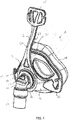
- Figures 1 and 2 represent general and exploded views of an embodiment of a respiratory mask 1, namely a facial mask, according to the present invention, comprising a hollow curved connector 10, a mask body or shell 2 defining an inner chamber 4 comprising a gas inlet 3 in fluid communication with said inner chamber 4 (cf. Fig. 2 ), and a front shroud 5, called “retainer”, “shroud” or “front piece”, that is sandwiched between the tubular gas connector 10 and the mask body 2 of the mask 1.
- the front shroud 5 comprises two lateral arms 12 and a flexible upper arm 6 that are integrally fixed to or molded in one-piece with the rest of the front shroud 5.
- the flexible upper arm 6 projects upwardly, i.e. about vertically, with respect to the mask body 2, whereas the two lateral arms 12 projecting laterally from said mask body 2 in opposite directions, i.e. one toward the right side of the mask 1 and the other toward the left side of the mask 1, as shown in Figures 1 and 2 .
- the two lateral arms 12 and the flexible upper arm 6 have free distal ends carrying headgear connecting structures 15, such as slots, hooks or the like, so as to fix a headgear thereto (not shown).
- a headgear typically comprises several straps of fabric and/or polymer materials, or the like, and is used for securing and maintaining the mask 1 in position on the patient's face, when the mask is used, i.e. worn by the patient.
- the flexible upper arm 6 and/or of the two lateral arms 12 have typically elongated shapes, for example band or ribbon shapes, and are made of a flexible material, such as a polymer material, e.g. polycarbonate (PC), polypropylene (PP) or nylon so as to be slightly bendable toward the patient's face under the forces applied by the headgear, when said headgear is adjusted to the morphology of the patient's head.
- a polymer material e.g. polycarbonate (PC), polypropylene (PP) or nylon
- the front shroud 5 can be made of the same polymer material or of any other suitable material.
- the shroud 5 further comprises a central aperture 9 that is traversed by part of the hollow connector 10, as illustrated in Figure 1 .
- the mask body 2 can be made from a unique piece or from several pieces or sub-units that are subsequently assembled together and made integral by means of any available fixing technique, for instance they can be glued, thermo-welded or similarly affixed together. It can be made of a polymer material that is also slightly flexible, preferably a polymer or plastic material, such as polypropylene (PP), polycarbonate (PC) and nylon, or similar.
- PP polypropylene
- PC polycarbonate
- nylon or similar.
- the facial mask 2 of the present invention also comprises a flexible cushion 16 that is fixed to the rear side of the mask body 2.
- the flexible cushion 16 is a tridimensional hollow structure forming an inner respiratory chamber 16a with a front aperture 16b adapted, i.e. conformed and sized, for receiving at least part of the nose and mouth of the patient as above explained, when the patient wears the mask, so that the patient can breathe the respiratory gas contained in the inner chamber 4 of the mask body 2 and/or in the respiratory chamber 16a of the cushion 16 as those chambers 4, 16a are in fluid communication with one another.
- the cushion 16 comprises a cushion body delimiting the respiratory chamber 16a and further comprises a rear aperture or rear opening delimited by a rear border that opens into the inner chamber 4 of the mask body 2, when the cushion 16 is firmly fixed to the mask body 2, so that gas can freely pass from the inner chamber 4 of the mask body 2 towards the respiratory chamber of the cushion 16, and vice versa.
- the inner chamber 4 of the mask body 2 and the respiratory chamber 16a of the cushion 16 form together a large inner compartment wherein the patient can inspire fresh gas, such as air, during inhalation phases, and exhale CO 2 -enriched gas, during expiration phases.
- the respiratory chamber 16a of the cushion 16 and the inner chamber 4 of the mask body 2 are both in fluid communication with the central gas passage, i.e. the lumen, of the elbow connector 10 so that a gas flow can freely travel from said tubular connector 10 to said chambers, or vice versa.
- the aperture 16b of the cushion 16 is delimited by a flexible membrane 16c that comes into contact with the patient's face and conforms with his/her facial morphology, when the mask 1 is worn by the patient.
- This membrane constitutes a kind of soft flexible skirt delimiting the front aperture of the cushion 16.
- two or more superimposed membranes can also be used as using several membranes may improve gas tightness in certain circumstances, e.g. for some particular patient's morphologies.
- the cushion 16 has, in the present case, a generally tridimensional (3D) trapezoidal shape, but other shapes are also possible such as triangular or saddle shapes, so as to better fit with the contours of the patient's face, especially in the nasal and mouth regions.
- 3D tridimensional
- the cushion 16 and the membrane forming the peripheral border or skirt of the front aperture of the cushion 16 are in contact with particular and well defined regions of the patient's face, thereby ensuring gas tightness.
- the cushion 16 is a facial cushion configured and sized for coming into contact, when the mask is worn by a user, with at least the nasal bridge region (including lateral nose regions), the chin region, i.e. the area located under the lower lip, and the cheek regions located on both lateral sizes of the nose and mouth of the patient, said cheek regions linking the nasal bridge region including lateral nose regions to the chin region.
- the nasal bridge region can be an area of the nose located either at the junction of bone and cartilage, or below or above said bone/cartilage junction of the nose; the chin region is expending from the lower lip to the chin, whereas the cheek regions are the opposite areas located on right and left sizes of the nose and mouth.
- other embodiments and shapes of the cushion 16 are possible.
- the cushion 16 (i.e., including cushion body and membrane) is preferably made of a flexible and soft material, such as silicone or the like.
- the membrane and the cushion body are molded in one piece.
- the cushion 16 is fixed to the mask body 2 by means of a male/female connecting system, such as male/female connections, that are configured or shaped so as to fit together for ensuring for instance a snap-fit connection, a "sandwich-type connection or the like. They can also be glued together or the like.
- a male/female connecting system such as male/female connections, that are configured or shaped so as to fit together for ensuring for instance a snap-fit connection, a "sandwich-type connection or the like. They can also be glued together or the like.
- the gas inlet 3 of the mask body 2 is designed for fixing thereto a tubular gas connector 10 as shown in Fig. 1-2 , so that the front shroud 5 is "sandwiched” and/or “squeezed” between the tubular connector 10 and the mask body 2.
- the hollow connector 10 has a tubular body traversed by an inner passage comprising an inlet and outlet orifices.
- the tubular body of the hollow connector 10 is preferably curved so as to have a L- or elbow-shape.
- the connector 1 further comprises an anti-asphyxia system comprising a venting port 13 cooperating with a mobile flap 14, i.e. a flexible flap, so as to allow the patient breathing fresh air through the venting port 13 in case of failure of the gas source, such as a medical ventilator, as shown in Fig. 1-2 .
- an anti-asphyxia system comprising a venting port 13 cooperating with a mobile flap 14, i.e. a flexible flap, so as to allow the patient breathing fresh air through the venting port 13 in case of failure of the gas source, such as a medical ventilator, as shown in Fig. 1-2 .
- a gas source such as a medical ventilator
- the upstream portion of the hollow connector 10 comprising the inlet orifice is fed with gas, such as pressurized air, by a flexible hose (not shown) or the like conveying the gas delivered by a medical gas source, such as a medical ventilator or apparatus.
- a medical gas source such as a medical ventilator or apparatus.
- the flexible hose is fluidly connected to the hollow connector 10 by means of an intermediary connector 17, i.e. a tubing element, that is preferably rotatable with respect to the hollow curved connector 10.
- the curved connector 10 further comprises a gas venting system comprising venting passage(s) and venting orifices 18 for recovering CO 2 -riched expired gases exhaled by the patient and for venting them to the ambient atmosphere.
- the venting holes 18 can be arranged in an array forming a circle or preferably an arc of circle (i.e., semi-circular array) as shown in Fig. 1-2 .
- the hollow connector 10 is entirely made of a plastic material, such as PP, PC or nylon. It is fluidly connected to the mask body 2 for feeding gas into the inner chamber 4. In other words, the gas that passes through the inner passage of the hollow curved connector 10 is subsequently delivered into the inner chamber 4 of the mask body 2 for being inhaled by a patient wearing the mask 1.
- the front piece or shroud 5 comprises a central aperture 9 or opening, as shown in Fig. 2 , and several headgear connecting structures 15, such as hooks and/or slots or similar, for receiving the straps of a headgear (not shown).
- the headgear connecting structures 15 are arranged at the free ends of the lateral arms 12 and the upper arm 6.
- the gas inlet 3 of the mask body 2 and the central aperture 9 of the front shroud 5 are traversed by the hollow connector 1 as shown in Fig. 1 , so that the front piece 5 is sandwiched and tightly hold between the mask body 21 and the hollow connector 10.
- the front piece 5 is squeezed between a collar element 11 arranged around the gas inlet 4 of the mask body 2, and the hollow curved connector 10.
- the hollow connector 10 can be snap-fitted into the gas inlet 4 of the mask body 2 thereby prohibiting any undesired withdrawal of the hollow connector 10 from the mask body 2.
- At least one (i.e. one or more) resilient element(s) 7 is(are) arranged between the mask body 2 and the flexible upper arm 6 of the front shroud 5.
- Said resilient element 7 is squeezed between the mask body 2 and the rear surface or side 6b of the flexible upper arm 6 of the front shroud 5, when the flexible upper arm 6 is bent toward the mask body 2, for instance when the headgear is adjusted to the facial morphology of a user.
- the resilient element 7 is arranged, e. g. glued or over-molded, on the peripheral outer wall 8 of the mask body 2.
- the resilient element 7 is made of resilient material, such as silicone or the like, that is able to be deformed when the flexible upper arm 6 of the front shroud 5 is bent toward the mask body 2 and mechanically acts on said resilient element 7.
- the resilient element 7 acts as a soft bumper or abutment that limits the course of the upper arm 6, when it pivots toward the mask body 2, when someone pulls on the straps of the headgear for adjusting said headgear to the morphology of the patient's face.
- the resilient element 7 can have a hemi-tubular shape, i.e. a hemi-cylinder, as shown in Figures 2-5 , or any other suitable or equivalent shape.
- the resilient element 7 can be made of a unique piece or unit, such as the hemi-cylinder shown in Figures 2-5 , or can be made of two or more sub-units or several pieces, that have a same shape or different shapes.
- the resilient element 7 can have a hollow structure, such as the hemi-cylinder of Figures 2-5 , or a non-hollow structure, i.e. a solid structure, for instance made of little block or piece of resilient material.
- the resilient element 7 is integrally fixed to the body 2, i.e. in a non-removable manner.
- the respiratory mask 1 of the present invention such as a nasal or facial mask, is light, comfortable to wear, easy to position and secure on the patient's face, and provide a good tightness, i.e. gas seal.
- the respiratory mask of the present invention can be used in a method for treatment of a respiratory disorder or condition affecting infant, toddler and child patients as well as adult patients, for example in non-invasive positive pressure ventilation (NPPV) or in a nasal continuous positive airway pressure (N-CPAP) therapy of sleep disordered breathing (SDB) conditions, such as, for example, obstructive sleep apnea (OSA).
- NPPV non-invasive positive pressure ventilation
- N-CPAP nasal continuous positive airway pressure
- SDB sleep disordered breathing
- OSA obstructive sleep apnea
Landscapes
- Health & Medical Sciences (AREA)
- Emergency Medicine (AREA)
- Pulmonology (AREA)
- Engineering & Computer Science (AREA)
- Anesthesiology (AREA)
- Biomedical Technology (AREA)
- Heart & Thoracic Surgery (AREA)
- Hematology (AREA)
- Life Sciences & Earth Sciences (AREA)
- Animal Behavior & Ethology (AREA)
- General Health & Medical Sciences (AREA)
- Public Health (AREA)
- Veterinary Medicine (AREA)
- Respiratory Apparatuses And Protective Means (AREA)
Claims (14)
- Atemmaske (1), umfassend:- einen Maskenkörper (2), umfassend einen Gaseinlass (3) in Fluidkommunikation mit einer internen Kammer (4),- eine Vorderabdeckung (5) mit einem flexiblen, aufwärts ragenden, oberen Arm (6), umfassend Kopfbedeckungsanschlussstrukturen (15), und- mindestens ein elastisches Element (7), das zwischen dem Maskenkörper (2) und dem flexiblen oberen Arm (6) der Vorderabdeckung (5) angeordnet ist, so dass das mindestens eine elastische Element (7) zwischen dem Maskenkörper (2) und dem flexiblen oberen Arm (6) eingeklemmt ist,dadurch gekennzeichnet, dass:- das elastische Element (7) einstückig, in nicht-abnehmbarer Weise auf der umlaufenden Außenwand (8) des Maskenkörpers (2) fixiert ist, und- das elastische Element (7) aus elastischem Material hergestellt ist, das fähig ist, verformt zu werden, wenn der flexible obere Arm (6) der Vorderabdeckung (5) gebogen oder zum Maskenkörper (2) gedreht wird und auf das elastische Element (7) mechanisch einwirkt.
- Atemmaske nach dem vorstehenden Anspruch, dadurch gekennzeichnet, dass das elastische Element (7) Silikon umfasst.
- Atemmaske nach einem der vorstehenden Ansprüche, dadurch gekennzeichnet, dass die Vorderabdeckung (5) eine mittlere Öffnung (9) umfasst, die koaxial mit dem Gaseinlass (3) des Maskenkörpers (2) angeordnet ist.
- Atemmaske nach einem der vorstehenden Ansprüche, dadurch gekennzeichnet, dass die mittlere Öffnung (9) der Vorderabdeckung (5) und der Gaseinlass (3) des Maskenkörpers (2) von einem hohlen Stutzen (10), vorzugsweise einem gekrümmten Stutzen (10) durchsetzt werden.
- Atemmaske nach einem der vorstehenden Ansprüche, dadurch gekennzeichnet, dass der Maskenkörper (2) ein Kragenelement (11) umfasst, das um den Gaseinlass (3) des Maskenkörpers (2) herum angeordnet ist, wobei die Vorderabdeckung (5) mit dem Kragenelement (11) zusammenwirkt.
- Atemmaske nach Anspruch 4, dadurch gekennzeichnet, dass der hohle Stutzen (10) in den Gaseinlass (3) des Maskenkörpers (2) einrastet.
- Atemmaske nach einem der vorstehenden Ansprüche, dadurch gekennzeichnet, dass die Vorderabdeckung (5) weiter zwei seitliche Arme (12) umfasst, die zur Seite ragen.
- Atemmaske nach Anspruch 7, dadurch gekennzeichnet, dass die zwei seitlichen Arme (12) Kopfbedeckungsanschlussstrukturen (15) umfassen, vorzugsweise eine Kopfbedeckung an den Kopfbedeckungsanschlussstrukturen (15) der Vorderabdeckung (5) fixiert wird.
- Atemmaske nach einem der vorstehenden Ansprüche, dadurch gekennzeichnet, dass die Vorderabdeckung, die den aufwärts ragenden, oberen Arm (6) und/oder die zwei seitlichen Arme umfasst, aus mindestens einem Polymermaterial hergestellt ist.
- Atemmaske nach einem der Ansprüche 1 bis 8, dadurch gekennzeichnet, dass sie weiter ein flexibles Kissen (16) umfasst, das an dem Maskenkörper (2) fixiert ist.
- Atemmaske nach einem der vorstehenden Ansprüche, dadurch gekennzeichnet, dass die Vorderabdeckung (5) mit dem Maskenkörper (2) durch den hohlen Stutzen (10) einstückig gehalten wird.
- Atemmaske nach einem der vorstehenden Ansprüche, dadurch gekennzeichnet, dass das mindestens eine elastische Element (7) eine hohle Struktur aufweist, vorzugsweise eine Schlauchstruktur, besonders bevorzugt eine Halbzylinderstruktur.
- Atemmaske nach einem der vorstehenden Ansprüche, dadurch gekennzeichnet, dass sie eine Gesichtsmaske ist.
- Anordnung zur Abgabe eines Gases an einen Patienten, umfassend eine Gasabgabevorrichtung, wie etwa ein Beatmungsgerät, und eine Atemmaske nach einem der vorstehenden Ansprüche.
Priority Applications (3)
| Application Number | Priority Date | Filing Date | Title |
|---|---|---|---|
| ES17305274T ES2778850T3 (es) | 2017-03-14 | 2017-03-14 | Máscara respiratoria con un elemento elástico entre el cuerpo de la máscara y la cubierta |
| EP17305274.7A EP3375476B1 (de) | 2017-03-14 | 2017-03-14 | Atemmaske mit einem elastischen element zwischen dem maskenkörper und der vorkammer |
| PT173052747T PT3375476T (pt) | 2017-03-14 | 2017-03-14 | Máscara respiratória com um elemento resiliente entre o corpo da máscara e cobertura |
Applications Claiming Priority (1)
| Application Number | Priority Date | Filing Date | Title |
|---|---|---|---|
| EP17305274.7A EP3375476B1 (de) | 2017-03-14 | 2017-03-14 | Atemmaske mit einem elastischen element zwischen dem maskenkörper und der vorkammer |
Publications (2)
| Publication Number | Publication Date |
|---|---|
| EP3375476A1 EP3375476A1 (de) | 2018-09-19 |
| EP3375476B1 true EP3375476B1 (de) | 2020-02-19 |
Family
ID=58413028
Family Applications (1)
| Application Number | Title | Priority Date | Filing Date |
|---|---|---|---|
| EP17305274.7A Active EP3375476B1 (de) | 2017-03-14 | 2017-03-14 | Atemmaske mit einem elastischen element zwischen dem maskenkörper und der vorkammer |
Country Status (3)
| Country | Link |
|---|---|
| EP (1) | EP3375476B1 (de) |
| ES (1) | ES2778850T3 (de) |
| PT (1) | PT3375476T (de) |
Families Citing this family (2)
| Publication number | Priority date | Publication date | Assignee | Title |
|---|---|---|---|---|
| EP3417898B1 (de) * | 2017-06-19 | 2020-10-07 | Löwenstein Medical Technology S.A. | Atemmaske mit kopplungselement für eine bänderung |
| EP3417900B1 (de) * | 2017-06-19 | 2020-08-19 | Löwenstein Medical Technology S.A. | Atemmaske mit mitteln zur ankopplung der bänderung |
Family Cites Families (12)
| Publication number | Priority date | Publication date | Assignee | Title |
|---|---|---|---|---|
| EP0462701B1 (de) | 1990-05-21 | 1994-12-14 | The University Of Sydney | Nasenmaske |
| US5438981A (en) | 1993-09-30 | 1995-08-08 | Respironics, Inc. | Automatic safety valve and diffuser for nasal and/or oral gas delivery mask |
| US5662101A (en) | 1995-12-07 | 1997-09-02 | Respironics, Inc. | Respiratory facial mask |
| AUPP794598A0 (en) | 1998-12-24 | 1999-01-28 | Resmed Limited | An anti-asphyxia valve |
| AUPP949999A0 (en) | 1999-03-29 | 1999-04-22 | Resmed Limited | Forehead support for facial mask II |
| US7219669B1 (en) | 1999-06-08 | 2007-05-22 | Sleepnet Corporation | Nose mask |
| US6631718B1 (en) | 1999-06-08 | 2003-10-14 | Sleepnet Corporation | Air mask with seal |
| US8245711B2 (en) * | 2005-08-15 | 2012-08-21 | Ric Investments, Llc | Patient interface with adjustable cushion |
| US9149596B2 (en) | 2007-03-23 | 2015-10-06 | Resmed Limited | Release mechanism for patient interface and method for releasing patient interface |
| DE202009018870U1 (de) | 2008-03-04 | 2014-02-03 | Resmed Ltd. | Maskensystem |
| WO2012020359A1 (en) * | 2010-08-09 | 2012-02-16 | Koninklijke Philips Electronics N.V. | Patient interface device including a dynamic self adjustment mechanism |
| JP6163160B2 (ja) * | 2011-11-15 | 2017-07-12 | コーニンクレッカ フィリップス エヌ ヴェKoninklijke Philips N.V. | 鼻梁に対する調整機能を備えた患者用インターフェース装置 |
-
2017
- 2017-03-14 PT PT173052747T patent/PT3375476T/pt unknown
- 2017-03-14 EP EP17305274.7A patent/EP3375476B1/de active Active
- 2017-03-14 ES ES17305274T patent/ES2778850T3/es active Active
Non-Patent Citations (1)
| Title |
|---|
| None * |
Also Published As
| Publication number | Publication date |
|---|---|
| EP3375476A1 (de) | 2018-09-19 |
| ES2778850T3 (es) | 2020-08-12 |
| PT3375476T (pt) | 2020-03-26 |
Similar Documents
| Publication | Publication Date | Title |
|---|---|---|
| EP2954920B1 (de) | Nasale Atemmaske mit flexiblen Armen | |
| EP3305354B1 (de) | Hohler gekrümmter verbinder mit mehreren sekundärteilstrukturen für eine atemmaske | |
| EP1778365B1 (de) | Flexible cpap-maske | |
| EP2414018B1 (de) | Maskensystem | |
| EP2474335B1 (de) | Verbessertes Kissen für Gesichtsmaske zur Behandlung von Schlafstörungen | |
| EP2818194A1 (de) | Nasen-Atemmaske, die integral aus Silikon besteht | |
| EP2329858A1 (de) | Nasale Atemmaske mit schwenkbarem Arm zum Halten und Ausrichten der Stirnstütze | |
| EP3952966A1 (de) | Dichtungsformende struktur, positionierungs- und stabilisierungsstruktur und diffusorentlüftung für patientenschnittstelle | |
| CN114650859B (zh) | 带有窗口的织物导管 | |
| EP3095478A1 (de) | Atemmaske mit verbessertem kissen | |
| EP3369451B1 (de) | Rahmenlose atemmaske | |
| EP2954919A1 (de) | Atemmaske mit Belüftungsöffnungen | |
| EP2954918B1 (de) | Neue Struktur für eine nasale Atemmaske | |
| EP3470101B1 (de) | Atemmaske mit schwenkbarem ellbogenverbinder und deckband | |
| EP2281597A1 (de) | Nasale Atemmaske mit einem drehbaren Gasanschlussstück mit einem oder mehreren Lüftungsanschlüssen | |
| EP3375476A1 (de) | Atemmaske mit einem elastischen element zwischen dem maskenkörper und der vorkammer | |
| EP2954921B1 (de) | Atemmaske mit einem anti-rotations System | |
| EP2478925B1 (de) | Verbessertes Membrankissen für Gesichtsmaske zur Behandlung von Schlafstörungen | |
| EP3246065B1 (de) | Leichte pädiatrische atemmaske | |
| EP3563895B1 (de) | Atemmaske mit einem flexiblen kissen, das lösbar an den maskenkörper befestigt ist | |
| EP3300761A1 (de) | Hohlverbinder mit entgasungssystem für atemmaske | |
| EP2818195B1 (de) | Pädiatrische atemmaske mit kugelkopfverbinder | |
| EP4631557A1 (de) | Nasale atemmaske mit minimalem kontakt und verbesserter seitenarmstruktur | |
| EP4635542A1 (de) | Verbesserte bänderung für eine nasale atemmaske | |
| EP2818193B1 (de) | Atemmaske mit abnehmbarem Haltearm |
Legal Events
| Date | Code | Title | Description |
|---|---|---|---|
| PUAI | Public reference made under article 153(3) epc to a published international application that has entered the european phase |
Free format text: ORIGINAL CODE: 0009012 |
|
| STAA | Information on the status of an ep patent application or granted ep patent |
Free format text: STATUS: THE APPLICATION HAS BEEN PUBLISHED |
|
| AK | Designated contracting states |
Kind code of ref document: A1 Designated state(s): AL AT BE BG CH CY CZ DE DK EE ES FI FR GB GR HR HU IE IS IT LI LT LU LV MC MK MT NL NO PL PT RO RS SE SI SK SM TR |
|
| AX | Request for extension of the european patent |
Extension state: BA ME |
|
| STAA | Information on the status of an ep patent application or granted ep patent |
Free format text: STATUS: REQUEST FOR EXAMINATION WAS MADE |
|
| 17P | Request for examination filed |
Effective date: 20190319 |
|
| RBV | Designated contracting states (corrected) |
Designated state(s): AL AT BE BG CH CY CZ DE DK EE ES FI FR GB GR HR HU IE IS IT LI LT LU LV MC MK MT NL NO PL PT RO RS SE SI SK SM TR |
|
| GRAP | Despatch of communication of intention to grant a patent |
Free format text: ORIGINAL CODE: EPIDOSNIGR1 |
|
| STAA | Information on the status of an ep patent application or granted ep patent |
Free format text: STATUS: GRANT OF PATENT IS INTENDED |
|
| INTG | Intention to grant announced |
Effective date: 20190918 |
|
| GRAS | Grant fee paid |
Free format text: ORIGINAL CODE: EPIDOSNIGR3 |
|
| GRAA | (expected) grant |
Free format text: ORIGINAL CODE: 0009210 |
|
| STAA | Information on the status of an ep patent application or granted ep patent |
Free format text: STATUS: THE PATENT HAS BEEN GRANTED |
|
| AK | Designated contracting states |
Kind code of ref document: B1 Designated state(s): AL AT BE BG CH CY CZ DE DK EE ES FI FR GB GR HR HU IE IS IT LI LT LU LV MC MK MT NL NO PL PT RO RS SE SI SK SM TR |
|
| REG | Reference to a national code |
Ref country code: CH Ref legal event code: EP |
|
| REG | Reference to a national code |
Ref country code: DE Ref legal event code: R096 Ref document number: 602017011951 Country of ref document: DE |
|
| REG | Reference to a national code |
Ref country code: AT Ref legal event code: REF Ref document number: 1234225 Country of ref document: AT Kind code of ref document: T Effective date: 20200315 |
|
| REG | Reference to a national code |
Ref country code: IE Ref legal event code: FG4D |
|
| REG | Reference to a national code |
Ref country code: PT Ref legal event code: SC4A Ref document number: 3375476 Country of ref document: PT Date of ref document: 20200326 Kind code of ref document: T Free format text: AVAILABILITY OF NATIONAL TRANSLATION Effective date: 20200316 |
|
| REG | Reference to a national code |
Ref country code: NL Ref legal event code: MP Effective date: 20200219 |
|
| PG25 | Lapsed in a contracting state [announced via postgrant information from national office to epo] |
Ref country code: FI Free format text: LAPSE BECAUSE OF FAILURE TO SUBMIT A TRANSLATION OF THE DESCRIPTION OR TO PAY THE FEE WITHIN THE PRESCRIBED TIME-LIMIT Effective date: 20200219 Ref country code: NO Free format text: LAPSE BECAUSE OF FAILURE TO SUBMIT A TRANSLATION OF THE DESCRIPTION OR TO PAY THE FEE WITHIN THE PRESCRIBED TIME-LIMIT Effective date: 20200519 Ref country code: RS Free format text: LAPSE BECAUSE OF FAILURE TO SUBMIT A TRANSLATION OF THE DESCRIPTION OR TO PAY THE FEE WITHIN THE PRESCRIBED TIME-LIMIT Effective date: 20200219 |
|
| REG | Reference to a national code |
Ref country code: ES Ref legal event code: FG2A Ref document number: 2778850 Country of ref document: ES Kind code of ref document: T3 Effective date: 20200812 |
|
| REG | Reference to a national code |
Ref country code: LT Ref legal event code: MG4D |
|
| PG25 | Lapsed in a contracting state [announced via postgrant information from national office to epo] |
Ref country code: BG Free format text: LAPSE BECAUSE OF FAILURE TO SUBMIT A TRANSLATION OF THE DESCRIPTION OR TO PAY THE FEE WITHIN THE PRESCRIBED TIME-LIMIT Effective date: 20200519 Ref country code: GR Free format text: LAPSE BECAUSE OF FAILURE TO SUBMIT A TRANSLATION OF THE DESCRIPTION OR TO PAY THE FEE WITHIN THE PRESCRIBED TIME-LIMIT Effective date: 20200520 Ref country code: IS Free format text: LAPSE BECAUSE OF FAILURE TO SUBMIT A TRANSLATION OF THE DESCRIPTION OR TO PAY THE FEE WITHIN THE PRESCRIBED TIME-LIMIT Effective date: 20200619 Ref country code: SE Free format text: LAPSE BECAUSE OF FAILURE TO SUBMIT A TRANSLATION OF THE DESCRIPTION OR TO PAY THE FEE WITHIN THE PRESCRIBED TIME-LIMIT Effective date: 20200219 Ref country code: LV Free format text: LAPSE BECAUSE OF FAILURE TO SUBMIT A TRANSLATION OF THE DESCRIPTION OR TO PAY THE FEE WITHIN THE PRESCRIBED TIME-LIMIT Effective date: 20200219 Ref country code: HR Free format text: LAPSE BECAUSE OF FAILURE TO SUBMIT A TRANSLATION OF THE DESCRIPTION OR TO PAY THE FEE WITHIN THE PRESCRIBED TIME-LIMIT Effective date: 20200219 |
|
| PG25 | Lapsed in a contracting state [announced via postgrant information from national office to epo] |
Ref country code: NL Free format text: LAPSE BECAUSE OF FAILURE TO SUBMIT A TRANSLATION OF THE DESCRIPTION OR TO PAY THE FEE WITHIN THE PRESCRIBED TIME-LIMIT Effective date: 20200219 |
|
| PG25 | Lapsed in a contracting state [announced via postgrant information from national office to epo] |
Ref country code: SK Free format text: LAPSE BECAUSE OF FAILURE TO SUBMIT A TRANSLATION OF THE DESCRIPTION OR TO PAY THE FEE WITHIN THE PRESCRIBED TIME-LIMIT Effective date: 20200219 Ref country code: DK Free format text: LAPSE BECAUSE OF FAILURE TO SUBMIT A TRANSLATION OF THE DESCRIPTION OR TO PAY THE FEE WITHIN THE PRESCRIBED TIME-LIMIT Effective date: 20200219 Ref country code: SM Free format text: LAPSE BECAUSE OF FAILURE TO SUBMIT A TRANSLATION OF THE DESCRIPTION OR TO PAY THE FEE WITHIN THE PRESCRIBED TIME-LIMIT Effective date: 20200219 Ref country code: EE Free format text: LAPSE BECAUSE OF FAILURE TO SUBMIT A TRANSLATION OF THE DESCRIPTION OR TO PAY THE FEE WITHIN THE PRESCRIBED TIME-LIMIT Effective date: 20200219 Ref country code: RO Free format text: LAPSE BECAUSE OF FAILURE TO SUBMIT A TRANSLATION OF THE DESCRIPTION OR TO PAY THE FEE WITHIN THE PRESCRIBED TIME-LIMIT Effective date: 20200219 Ref country code: LT Free format text: LAPSE BECAUSE OF FAILURE TO SUBMIT A TRANSLATION OF THE DESCRIPTION OR TO PAY THE FEE WITHIN THE PRESCRIBED TIME-LIMIT Effective date: 20200219 Ref country code: CZ Free format text: LAPSE BECAUSE OF FAILURE TO SUBMIT A TRANSLATION OF THE DESCRIPTION OR TO PAY THE FEE WITHIN THE PRESCRIBED TIME-LIMIT Effective date: 20200219 |
|
| REG | Reference to a national code |
Ref country code: CH Ref legal event code: PL |
|
| REG | Reference to a national code |
Ref country code: AT Ref legal event code: MK05 Ref document number: 1234225 Country of ref document: AT Kind code of ref document: T Effective date: 20200219 |
|
| REG | Reference to a national code |
Ref country code: DE Ref legal event code: R097 Ref document number: 602017011951 Country of ref document: DE |
|
| PG25 | Lapsed in a contracting state [announced via postgrant information from national office to epo] |
Ref country code: MC Free format text: LAPSE BECAUSE OF FAILURE TO SUBMIT A TRANSLATION OF THE DESCRIPTION OR TO PAY THE FEE WITHIN THE PRESCRIBED TIME-LIMIT Effective date: 20200219 |
|
| REG | Reference to a national code |
Ref country code: BE Ref legal event code: MM Effective date: 20200331 |
|
| PLBE | No opposition filed within time limit |
Free format text: ORIGINAL CODE: 0009261 |
|
| STAA | Information on the status of an ep patent application or granted ep patent |
Free format text: STATUS: NO OPPOSITION FILED WITHIN TIME LIMIT |
|
| PG25 | Lapsed in a contracting state [announced via postgrant information from national office to epo] |
Ref country code: LU Free format text: LAPSE BECAUSE OF NON-PAYMENT OF DUE FEES Effective date: 20200314 |
|
| 26N | No opposition filed |
Effective date: 20201120 |
|
| PG25 | Lapsed in a contracting state [announced via postgrant information from national office to epo] |
Ref country code: LI Free format text: LAPSE BECAUSE OF NON-PAYMENT OF DUE FEES Effective date: 20200331 Ref country code: CH Free format text: LAPSE BECAUSE OF NON-PAYMENT OF DUE FEES Effective date: 20200331 Ref country code: AT Free format text: LAPSE BECAUSE OF FAILURE TO SUBMIT A TRANSLATION OF THE DESCRIPTION OR TO PAY THE FEE WITHIN THE PRESCRIBED TIME-LIMIT Effective date: 20200219 Ref country code: IE Free format text: LAPSE BECAUSE OF NON-PAYMENT OF DUE FEES Effective date: 20200314 |
|
| PG25 | Lapsed in a contracting state [announced via postgrant information from national office to epo] |
Ref country code: PL Free format text: LAPSE BECAUSE OF FAILURE TO SUBMIT A TRANSLATION OF THE DESCRIPTION OR TO PAY THE FEE WITHIN THE PRESCRIBED TIME-LIMIT Effective date: 20200219 Ref country code: BE Free format text: LAPSE BECAUSE OF NON-PAYMENT OF DUE FEES Effective date: 20200331 Ref country code: SI Free format text: LAPSE BECAUSE OF FAILURE TO SUBMIT A TRANSLATION OF THE DESCRIPTION OR TO PAY THE FEE WITHIN THE PRESCRIBED TIME-LIMIT Effective date: 20200219 |
|
| PGFP | Annual fee paid to national office [announced via postgrant information from national office to epo] |
Ref country code: PT Payment date: 20210315 Year of fee payment: 5 |
|
| GBPC | Gb: european patent ceased through non-payment of renewal fee |
Effective date: 20210314 |
|
| PG25 | Lapsed in a contracting state [announced via postgrant information from national office to epo] |
Ref country code: GB Free format text: LAPSE BECAUSE OF NON-PAYMENT OF DUE FEES Effective date: 20210314 |
|
| PG25 | Lapsed in a contracting state [announced via postgrant information from national office to epo] |
Ref country code: TR Free format text: LAPSE BECAUSE OF FAILURE TO SUBMIT A TRANSLATION OF THE DESCRIPTION OR TO PAY THE FEE WITHIN THE PRESCRIBED TIME-LIMIT Effective date: 20200219 Ref country code: MT Free format text: LAPSE BECAUSE OF FAILURE TO SUBMIT A TRANSLATION OF THE DESCRIPTION OR TO PAY THE FEE WITHIN THE PRESCRIBED TIME-LIMIT Effective date: 20200219 Ref country code: CY Free format text: LAPSE BECAUSE OF FAILURE TO SUBMIT A TRANSLATION OF THE DESCRIPTION OR TO PAY THE FEE WITHIN THE PRESCRIBED TIME-LIMIT Effective date: 20200219 |
|
| PG25 | Lapsed in a contracting state [announced via postgrant information from national office to epo] |
Ref country code: MK Free format text: LAPSE BECAUSE OF FAILURE TO SUBMIT A TRANSLATION OF THE DESCRIPTION OR TO PAY THE FEE WITHIN THE PRESCRIBED TIME-LIMIT Effective date: 20200219 Ref country code: AL Free format text: LAPSE BECAUSE OF FAILURE TO SUBMIT A TRANSLATION OF THE DESCRIPTION OR TO PAY THE FEE WITHIN THE PRESCRIBED TIME-LIMIT Effective date: 20200219 |
|
| PG25 | Lapsed in a contracting state [announced via postgrant information from national office to epo] |
Ref country code: PT Free format text: LAPSE BECAUSE OF NON-PAYMENT OF DUE FEES Effective date: 20220914 |
|
| PGFP | Annual fee paid to national office [announced via postgrant information from national office to epo] |
Ref country code: ES Payment date: 20250429 Year of fee payment: 9 |
|
| PGFP | Annual fee paid to national office [announced via postgrant information from national office to epo] |
Ref country code: DE Payment date: 20260319 Year of fee payment: 10 |
|
| PGFP | Annual fee paid to national office [announced via postgrant information from national office to epo] |
Ref country code: IT Payment date: 20260320 Year of fee payment: 10 |
|
| PGFP | Annual fee paid to national office [announced via postgrant information from national office to epo] |
Ref country code: FR Payment date: 20260320 Year of fee payment: 10 |