EP3375496B1 - Machine smith à angle réglable et pouvant pivoter - Google Patents
Machine smith à angle réglable et pouvant pivoter Download PDFInfo
- Publication number
- EP3375496B1 EP3375496B1 EP16864570.3A EP16864570A EP3375496B1 EP 3375496 B1 EP3375496 B1 EP 3375496B1 EP 16864570 A EP16864570 A EP 16864570A EP 3375496 B1 EP3375496 B1 EP 3375496B1
- Authority
- EP
- European Patent Office
- Prior art keywords
- angle
- barbell
- swing
- smith machine
- adjustable
- Prior art date
- Legal status (The legal status is an assumption and is not a legal conclusion. Google has not performed a legal analysis and makes no representation as to the accuracy of the status listed.)
- Active
Links
- 230000008878 coupling Effects 0.000 claims description 2
- 238000010168 coupling process Methods 0.000 claims description 2
- 238000005859 coupling reaction Methods 0.000 claims description 2
- 238000000926 separation method Methods 0.000 claims description 2
- 210000003205 muscle Anatomy 0.000 description 10
- 230000000694 effects Effects 0.000 description 5
- 230000005611 electricity Effects 0.000 description 4
- 238000010586 diagram Methods 0.000 description 2
- 201000010099 disease Diseases 0.000 description 2
- 208000037265 diseases, disorders, signs and symptoms Diseases 0.000 description 2
- 238000012986 modification Methods 0.000 description 2
- 230000004048 modification Effects 0.000 description 2
- 230000003387 muscular Effects 0.000 description 2
- 206010039722 scoliosis Diseases 0.000 description 2
- 238000005728 strengthening Methods 0.000 description 2
- 210000000481 breast Anatomy 0.000 description 1
- 244000309466 calf Species 0.000 description 1
- 210000000088 lip Anatomy 0.000 description 1
- 230000004936 stimulating effect Effects 0.000 description 1
- 210000000689 upper leg Anatomy 0.000 description 1
Images




Classifications
-
- A—HUMAN NECESSITIES
- A63—SPORTS; GAMES; AMUSEMENTS
- A63B—APPARATUS FOR PHYSICAL TRAINING, GYMNASTICS, SWIMMING, CLIMBING, OR FENCING; BALL GAMES; TRAINING EQUIPMENT
- A63B21/00—Exercising apparatus for developing or strengthening the muscles or joints of the body by working against a counterforce, with or without measuring devices
- A63B21/06—User-manipulated weights
- A63B21/072—Dumb-bells, bar-bells or the like, e.g. weight discs having an integral peripheral handle
-
- A—HUMAN NECESSITIES
- A63—SPORTS; GAMES; AMUSEMENTS
- A63B—APPARATUS FOR PHYSICAL TRAINING, GYMNASTICS, SWIMMING, CLIMBING, OR FENCING; BALL GAMES; TRAINING EQUIPMENT
- A63B21/00—Exercising apparatus for developing or strengthening the muscles or joints of the body by working against a counterforce, with or without measuring devices
- A63B21/06—User-manipulated weights
- A63B21/062—User-manipulated weights including guide for vertical or non-vertical weights or array of weights to move against gravity forces
- A63B21/0626—User-manipulated weights including guide for vertical or non-vertical weights or array of weights to move against gravity forces with substantially vertical guiding means
-
- A—HUMAN NECESSITIES
- A63—SPORTS; GAMES; AMUSEMENTS
- A63B—APPARATUS FOR PHYSICAL TRAINING, GYMNASTICS, SWIMMING, CLIMBING, OR FENCING; BALL GAMES; TRAINING EQUIPMENT
- A63B21/00—Exercising apparatus for developing or strengthening the muscles or joints of the body by working against a counterforce, with or without measuring devices
- A63B21/0004—Exercising devices moving as a whole during exercise
-
- A—HUMAN NECESSITIES
- A63—SPORTS; GAMES; AMUSEMENTS
- A63B—APPARATUS FOR PHYSICAL TRAINING, GYMNASTICS, SWIMMING, CLIMBING, OR FENCING; BALL GAMES; TRAINING EQUIPMENT
- A63B21/00—Exercising apparatus for developing or strengthening the muscles or joints of the body by working against a counterforce, with or without measuring devices
- A63B21/06—User-manipulated weights
- A63B21/062—User-manipulated weights including guide for vertical or non-vertical weights or array of weights to move against gravity forces
- A63B21/0622—User-manipulated weights including guide for vertical or non-vertical weights or array of weights to move against gravity forces with adjustable inclination angle of the guiding means
-
- A—HUMAN NECESSITIES
- A63—SPORTS; GAMES; AMUSEMENTS
- A63B—APPARATUS FOR PHYSICAL TRAINING, GYMNASTICS, SWIMMING, CLIMBING, OR FENCING; BALL GAMES; TRAINING EQUIPMENT
- A63B21/00—Exercising apparatus for developing or strengthening the muscles or joints of the body by working against a counterforce, with or without measuring devices
- A63B21/06—User-manipulated weights
- A63B21/072—Dumb-bells, bar-bells or the like, e.g. weight discs having an integral peripheral handle
- A63B21/0724—Bar-bells; Hand bars
-
- A—HUMAN NECESSITIES
- A63—SPORTS; GAMES; AMUSEMENTS
- A63B—APPARATUS FOR PHYSICAL TRAINING, GYMNASTICS, SWIMMING, CLIMBING, OR FENCING; BALL GAMES; TRAINING EQUIPMENT
- A63B21/00—Exercising apparatus for developing or strengthening the muscles or joints of the body by working against a counterforce, with or without measuring devices
- A63B21/06—User-manipulated weights
- A63B21/072—Dumb-bells, bar-bells or the like, e.g. weight discs having an integral peripheral handle
- A63B21/075—Dumb-bells, bar-bells or the like, e.g. weight discs having an integral peripheral handle with variable weights, e.g. weight systems with weight selecting means for bar-bells or dumb-bells
-
- A—HUMAN NECESSITIES
- A63—SPORTS; GAMES; AMUSEMENTS
- A63B—APPARATUS FOR PHYSICAL TRAINING, GYMNASTICS, SWIMMING, CLIMBING, OR FENCING; BALL GAMES; TRAINING EQUIPMENT
- A63B21/00—Exercising apparatus for developing or strengthening the muscles or joints of the body by working against a counterforce, with or without measuring devices
- A63B21/06—User-manipulated weights
- A63B21/078—Devices for bench press exercises, e.g. supports, guiding means
-
- A—HUMAN NECESSITIES
- A63—SPORTS; GAMES; AMUSEMENTS
- A63B—APPARATUS FOR PHYSICAL TRAINING, GYMNASTICS, SWIMMING, CLIMBING, OR FENCING; BALL GAMES; TRAINING EQUIPMENT
- A63B21/00—Exercising apparatus for developing or strengthening the muscles or joints of the body by working against a counterforce, with or without measuring devices
- A63B21/06—User-manipulated weights
- A63B21/078—Devices for bench press exercises, e.g. supports, guiding means
- A63B21/0783—Safety features for bar-bells, e.g. drop limiting means
-
- A—HUMAN NECESSITIES
- A63—SPORTS; GAMES; AMUSEMENTS
- A63B—APPARATUS FOR PHYSICAL TRAINING, GYMNASTICS, SWIMMING, CLIMBING, OR FENCING; BALL GAMES; TRAINING EQUIPMENT
- A63B21/00—Exercising apparatus for developing or strengthening the muscles or joints of the body by working against a counterforce, with or without measuring devices
- A63B21/15—Arrangements for force transmissions
- A63B21/151—Using flexible elements for reciprocating movements, e.g. ropes or chains
-
- A—HUMAN NECESSITIES
- A63—SPORTS; GAMES; AMUSEMENTS
- A63B—APPARATUS FOR PHYSICAL TRAINING, GYMNASTICS, SWIMMING, CLIMBING, OR FENCING; BALL GAMES; TRAINING EQUIPMENT
- A63B21/00—Exercising apparatus for developing or strengthening the muscles or joints of the body by working against a counterforce, with or without measuring devices
- A63B21/15—Arrangements for force transmissions
- A63B21/151—Using flexible elements for reciprocating movements, e.g. ropes or chains
- A63B21/154—Using flexible elements for reciprocating movements, e.g. ropes or chains using special pulley-assemblies
- A63B21/156—Using flexible elements for reciprocating movements, e.g. ropes or chains using special pulley-assemblies the position of the pulleys being variable, e.g. for different exercises
-
- A—HUMAN NECESSITIES
- A63—SPORTS; GAMES; AMUSEMENTS
- A63B—APPARATUS FOR PHYSICAL TRAINING, GYMNASTICS, SWIMMING, CLIMBING, OR FENCING; BALL GAMES; TRAINING EQUIPMENT
- A63B24/00—Electric or electronic controls for exercising apparatus of preceding groups; Controlling or monitoring of exercises, sportive games, training or athletic performances
- A63B24/0087—Electric or electronic controls for exercising apparatus of groups A63B21/00 - A63B23/00, e.g. controlling load
-
- A—HUMAN NECESSITIES
- A63—SPORTS; GAMES; AMUSEMENTS
- A63B—APPARATUS FOR PHYSICAL TRAINING, GYMNASTICS, SWIMMING, CLIMBING, OR FENCING; BALL GAMES; TRAINING EQUIPMENT
- A63B21/00—Exercising apparatus for developing or strengthening the muscles or joints of the body by working against a counterforce, with or without measuring devices
- A63B21/40—Interfaces with the user related to strength training; Details thereof
- A63B21/4027—Specific exercise interfaces
- A63B21/4029—Benches specifically adapted for exercising
-
- A—HUMAN NECESSITIES
- A63—SPORTS; GAMES; AMUSEMENTS
- A63B—APPARATUS FOR PHYSICAL TRAINING, GYMNASTICS, SWIMMING, CLIMBING, OR FENCING; BALL GAMES; TRAINING EQUIPMENT
- A63B2220/00—Measuring of physical parameters relating to sporting activity
- A63B2220/20—Distances or displacements
-
- A—HUMAN NECESSITIES
- A63—SPORTS; GAMES; AMUSEMENTS
- A63B—APPARATUS FOR PHYSICAL TRAINING, GYMNASTICS, SWIMMING, CLIMBING, OR FENCING; BALL GAMES; TRAINING EQUIPMENT
- A63B2220/00—Measuring of physical parameters relating to sporting activity
- A63B2220/20—Distances or displacements
- A63B2220/24—Angular displacement
-
- A—HUMAN NECESSITIES
- A63—SPORTS; GAMES; AMUSEMENTS
- A63B—APPARATUS FOR PHYSICAL TRAINING, GYMNASTICS, SWIMMING, CLIMBING, OR FENCING; BALL GAMES; TRAINING EQUIPMENT
- A63B71/00—Games or sports accessories not covered in groups A63B1/00 - A63B69/00
- A63B71/06—Indicating or scoring devices for games or players, or for other sports activities
Definitions
- the present invention relates to an angle-adjustable and swingable Smith machine that is manual or electrical. Additionally, the present invention relates to a training machine having a structure and an exercise effect similar to those of the Smith machine.
- Exercise apparatuses are divided into exercise apparatuses for upper body training and exercise apparatuses for lower body training.
- a weight capable of being adjusted according to a user, is provided in such exercise apparatuses for the user to perform muscular exercise of an upper body or a lower body.
- a lower body exercise apparatus is an exercise apparatus for strengthening calf muscles and thigh muscles
- an upper body exercise apparatus is an exercise apparatus for strengthening back muscles and shoulder muscles of the user or arm muscles of the user.
- an exercise apparatus referred to as a so-called Smith machine, which includes two supporting frames located on both sides that correspond to each other, a barbell bar held between the two supporting frames, and disc type weights which fit onto ends of the barbell bar such that the user inserts disciform weights, which weigh as much as the user chooses, onto the ends of the barbell bar and then proceeds to exercise.
- Smith machine which includes two supporting frames located on both sides that correspond to each other, a barbell bar held between the two supporting frames, and disc type weights which fit onto ends of the barbell bar such that the user inserts disciform weights, which weigh as much as the user chooses, onto the ends of the barbell bar and then proceeds to exercise.
- the supporting frames function merely as a guide to allow the barbell bar to move upward or downward.
- the conventional Smith machine does not have a function of leveling according to a condition of a bottom surface on which the Smith machine is disposed. Accordingly, the barbell may not be leveled such that an exercise leaning phenomenon, in which a force is further used to be biased toward a left side or a right side based on a philtrum of the user, occurs during exercise. In this case, an error in which muscles of any one of the left side or the right side are more developed may occur and a problem of a disease such as scoliosis may be caused.
- a bench located in the center thereof may be used.
- an indicating portion capable of indicating a position of the bench is not included, it may not be possible to locate the bench in the exact center of the Smith machine. Accordingly, also upon exercise lifting the barbell when the bench is not located in the exact center, the same problem as when the barbell is held at different left and right intervals may occur.
- Canadian patent CA1288790 C discloses an angle-adjustable and swingable Smith machine according to the preamble of claim 1.
- the present invention is directed to providing an angle-adjustable and swingable Smith machine in which a frame configured to guide upward or downward movements of a barbell bar is allowed to swing such that exercise effects may vary according to swing angles.
- the present invention is also directed to providing an angle-adjustable and swingable Smith machine for leveling barbells with a bottom surface.
- the present invention is also directed to providing an angle-adjustable and swingable Smith machine capable of centering barbells and locating benches in the exact center of the Smith machine.
- One aspect of the present invention provides an angle-adjustable and a swingable Smith machine including a frame portion which forms an exercise space, a swing portion disposed in the exercise space and connected to the frame portion, the swing portion including first and second vertical bars arranged at an interval, a horizontal bar configured to connect top ends of the first and second vertical bars, and a holding member installed on one side of each of the first and second vertical bars and including a plurality of concave portions formed thereon, a guide portion integrally coupled to the swing portion to swing therewith, a rail portion installed at a top end of the frame portion and configured to guide a movement of the swing portion when an angle of the swing portion is adjusted and configured to have a plurality of fixing grooves formed on at least one side of the rail portion to set or to fix an angle of the swing portion, an angle adjusting portion for adjusting the angle of the swing portion in connection with the rail portion, and a barbell portion coupled to the guide portion to move upward or downward.
- the angle-adjustable and swingable Smith machine is characterized in that the swing portion further includes a supporting roller portion installed in a top end of the horizontal bar to engage with a top end of the rail portion and configured to move along the top end of the rail portion, the rail portion is configured to connect a front and a rear of the top end of the frame portion, and the angle adjusting portion includes a main adjustor installed on one side of the first vertical bar to operate when a user adjusts the angle of the swing portion, a pivoting bar in which a bottom thereof is hinge-coupled to the first vertical bar and a top thereof pivots according to a movement of the main adjustor, an operating rod connected to a top end of the pivoting bar and installed on the horizontal bar while extending toward the rail portion, and an angle adjustor installed on an end of the operating rod and configured to be inserted into one of the fixing grooves according to a translation movement of the operating rod.
- a main adjustor installed on one side of the first vertical bar to operate when a user adjusts the angle of the swing portion
- the angle-adjustable and swingable Smith machine may include a sensor portion configured to sense a current barbell angle and a position and an operation panel for display.
- Another aspect of the present invention provides an angle-adjustable and swingable Smith machine, in addition to one aspect, including a screw motor and a screw bar connected to bottom ends of the frame portion and the swing portion to adjust the angle of the swing portion and a barbell portion coupled to the guide portion to be movable upward or downward.
- one of two types of manually or automatically operated apparatuses using electricity may be selected, a variety of angles corresponding to desired muscle areas may be set, a barbell may be stably moved upward or downward according to a set path, and a set angle or a free angle may be adjusted such that the same effect as that of naturally doing exercise using a conventional barbell may be obtained.
- a barbell may be located to be leveled with the bottom surface such that precise left and right symmetrical exercises may be performed without a leaning phenomenon.
- the barbell when a barbell of a Smith machine is held, the barbell may be gripped at precise left and right intervals due to an indicating function.
- a display function and a fixing device capable of locating a bench in the exact center of a Smith machine are included, when breast exercises such as bench presses are performed, precise left and right symmetrical exercises may be performed without the leaning phenomenon.
- a part through which a user enters and exits is referred to as a front and another part opposite thereto is referred to as a rear.
- the Smith machine according to the first embodiment of the present invention is a Smith machine used in a manual mode.
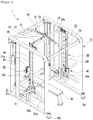
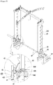
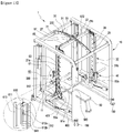
- the angle-adjustable and swingable Smith machine (hereinafter, the Smith machine) 1 includes a frame portion 10 which forms an exercise space, a swing portion 20 disposed in the exercise space and connected to the frame portion, a guide portion 50 integrally connected to the swing portion 20 to perform a swing operation therewith, a rail portion 30 installed at a top end of the frame portion 10 and configured to guide a movement of the swing portion 20 and set or fix an angle of the swing portion 20, an angle adjusting portion 60 for adjusting the angle of the swing portion 20 in connection with the rail portion 30, and a barbell portion 40 coupled to the guide portion 50 to move upward or downward.
- the Smith machine 1 includes a frame portion 10 which forms an exercise space, a swing portion 20 disposed in the exercise space and connected to the frame portion, a guide portion 50 integrally connected to the swing portion 20 to perform a swing operation therewith, a rail portion 30 installed at a top end of the frame portion 10 and configured to guide a movement of the swing portion 20 and set or fix an angle of the swing portion 20, an angle
- the frame portion 10 forms a frame having a rectangular-parallelepiped shape and a support body for supporting and fixing a variety of components of the present invention.
- the frame portion 10 is described as the frame having the rectangular-parallelepiped shape in the present invention but may have a variety of modifications in shape thereof.
- the swing portion 20 includes a pair of vertical bars 21a and 21b arranged at an interval in the exercise space in the frame portion 10 and a horizontal bar 23 configured to connect the pair of vertical bars from above.
- a holding member 25 in which a plurality of concaved portions for holding a held piece of a barbell are installed on one side surface of each of the vertical bars 21a and 21b.
- the vertical bars and the horizontal bar are integrally coupled to pivot with the swing operation of the swing portion 20.
- a top end of the swing portion 20 is pivotably spaced apart from the frame portion 10, and a bottom end thereof is pivotably coupled to a fixing bearing portion 11 installed on one side of the frame portion 10. Accordingly, the swing portion 20 may pivot on the fixing bearing portion 11 as the center of a hinge shaft.
- the guide portion 50 includes a pair of guide bars 51a and 51b installed to be spaced apart from and be parallel to the vertical bars 21a and 21b of the swing portion 20.
- Sliding members 53a and 53b are slidably installed on the pair of guide bars 51a and 51b and vertically move upward or downward along the guide bars.
- the barbell portion 40 is located between the guide bars 51a and 51b and the vertical bars 21a and 21b.
- the barbell portion 40 is coupled to the sliding members 53a and 53b such that the sliding members 53a and 53b move upward or downward along the guide bars 51a and 51b according to upward or downward movement of the barbell portion 40.
- the rail portion 30 has an arc-shaped thin plate structure which connects a front and a rear of a center at the top end of the frame portion 10 and shares a central point of the fixing bearing portion 11.
- a plurality of fixing grooves 31 are formed at a side surface of the rail portion 30 to be used for pivoting the swing portion 20 by a set angle and fixing the swing portion 20 at a position.
- a long slot 33 is formed in a certain range including a central part of the rail portion 30 such that the swing portion 20 is freely pivotable within a certain range of angles, for example, -15 to 15 degrees.
- the swing portion 20 may be fixed at a certain angle within the range of the slot 33 for freely pivoting the swing portion according to user's needs.
- the fixing grooves 31 are installed to be spaced apart at certain intervals such that an angle may be changed whenever the swing portion 20 pivots and then may be fixed.
- a supporting roller portion 27 is installed in a center of a top end of the horizontal bar 23 of the swing portion 20.
- a roller of the supporting roller portion 27 has a groove slightly wider than a thickness of the rail portion 30 to engage with a top end of the rail portion 30 to guide and support a pivoting movement of the swing portion 20.
- the angle adjusting portion 60 is for adjusting the angle of the swing portion 20 in connection with the rail portion 30.
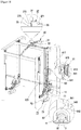
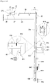
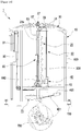
- the angle adjusting portion 60 includes a main adjustor 61 installed on one side of the vertical bar 21a to operate when a user adjusts an angle, a pivoting bar 63 to which the main adjustor 61 is connected and in which a bottom thereof hinge-coupled and a top thereof pivots, an operating rod 65 connected to a top end of the pivoting bar 63 and configured to extend to and installed at the rail portion 30, and an angle adjustor 67 installed at an end of the operating rod 65 and configured to operate along translation of the operating rod 65.
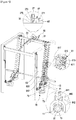
- the main adjustor 61 has a structure to be gripped and adjusted by a user and includes a gripping portion 613 connected to the vertical bar 21a of the swing portion 20, a connecting plate 617 fixed to the pivoting bar 63, a handle 611 disposed in the gripping portion 613 and coupled to the connecting plate 617, and a stopper 615 configured to restrict an operation of the handle 611.
- the gripping portion 613 is for locating a palm of the user and functions as a support.
- the connecting plate 617 functions as an adapter for connecting the handle 611 to the pivoting bar 63.
- the handle 611 is operated by pulling by the user's hand and has a structure capable of returning toward the swing portion 20 due to a restoring force of a spring (not shown) in a housing of the angle adjustor 67 when the user takes the hand off the handle 611.
- the stopper 615 is for restoring a movement of the handle 611 and allows the angle adjustor 67 to move only in the slot 33.
- a spring 619 for allowing the stopper 615 to return to an original position thereof is coupled to the stopper 615. That is, when the stopper 615 is pivoted counterclockwise viewed from the gripping portion 613, the movement of the handle 611 may be restricted. When the stopper 615 pivots clockwise due to the restoring force of the spring 619, the handle 611 may freely move.
- a fixing hole 614 is formed in one side of the stopper 615, and a protruding pin 612 capable of being inserted into the fixing hole 614 is integrally formed at the handle 611. Accordingly, when the handle 611 is released while the stopper 615 has pivoted counterclockwise, the protruding pin 612 of the handle 611 is inserted into the fixing hole 614 of the stopper 615 such that the handle 611 is not movable any longer. In this state, when the handle is pulled again, the stopper 615 returns to the original position due to the spring 619 and the handle 611 freely moves.
- the protruding pin 612 may have a shape with protrusions of two lengths.
- a first protrusion 612a and a second protrusion 612b are provided, and the first protrusion 612a is used in a manual mode and the second protrusion 612b is used in an automatic mode.
- the first protrusion 612a and the second protrusion 612b are rotatably mounted and changeable in positions.
- the first protrusion 612a may have a protruding length smaller than that of the second protrusion 612b.
- a stopper restricting rod 641 coupled to the swing portion 20 to restrict pivoting of the stopper 615 and configured to restrict or release the pivoting of the stopper 615
- a horseshoe-shaped fixing piece 642 which includes a concave groove 643 formed on a top end thereof to vertically move the stopper restricting rod 641
- a tensile spring 645 installed to allow the stopper restricting rod 641 to constantly have a force to move downward, and a restricting pin 618 formed to protrude from the stopper 615 toward the stopper restricting rod.
- the stopper 615 has been moved downward and may freely pivot in this state.
- the stopper restricting rod 641 pivots by the same angle as that of the swing portion 20 and deviates from the concave groove 643 of the horseshoe-shaped fixing piece 642 and is located higher to move upward. In this state, a restricting pin 618 of the stopper 615 is held by the stopper restricting rod 641 not to be pivotable.
- the pivoting bar 63 is installed lengthwise at the vertical bar 21a of the swing portion 20 along a longitudinal direction thereof and may pivot laterally on a pivoting hinge shaft 623 located at a bottom end.
- the operating rod 65 has one side connected to the top end of the pivoting bar 63, and is installed to extend toward the rail portion 30 along the horizontal bar 23.
- the operating rod 65 may translate onto the horizontal bar 23 according to pivoting of the top end of the pivoting bar 63.
- the angle adjustor 67 is integrally installed on the other side of the operating rod 65.
- the angle adjustor 67 may be inserted into the fixing groove 31 formed at the rail portion 30 or may freely move along the slot 33.
- the angle adjustor 67 includes a body 271, a fixing protrusion 273 integrally formed at a front end of the body 271, and a free protrusion 275 integrally formed at a front end of the fixing protrusion 273.
- a diameter of the free protrusion 275 may be smaller than a diameter of the fixing protrusion 273 and may have a size capable of freely moving on the slot 33.
- the diameter of the fixing protrusion 273 may have a size capable of being inserted into the fixing groove 31.
- the angle adjustor 67 includes an adjusting pin and a spring in the body 272 to return to the original position.
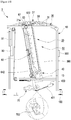
- the vertical bars 21a and 21b of the swing portion 20 are installed above one side of a rotating shaft 13 of the fixing bearing portion 11, and a swing portion compensating member 70 is installed below the other side thereof.
- the swing portion compensating member 70 balances zero by compensating the entire weight of the swing portion 20 and includes a compensating frame 73 coupled to the rotating shaft 13 and a plurality of swing weights 75 coupled to the compensating frame 73.
- the compensating frame 73 may have an L-shaped structure bent in an opposite direction in which the barbell portion 40 is located, that is, toward the rear of the Smith machine 1.
- a shape of the compensating frame 73 is for efficiently compensating a weight in a small space by locating the swing weights 75 in a direction opposite to a rotational direction of the swing portion 20.
- the number or weights of the plurality of swing weights 75 may vary according to the entire weight of the swing portion 20.
- the barbell portion 40 is installed throughout left and right sides of the frame portion 10 and has a bar shape which extends lengthwise.
- the barbell portion 40 includes a barbell 41 having a long bar shape, a held piece 43 fixedly installed on both sides of the barbell 41 and held by and located at a concave portion 253 of the holding member 25, and a barbell connecting plate 45 for coupling the barbell 41 to the sliding members 53a and 53b of the guide portion 50.
- the sliding members 53a and 53b may vertically slide along the guide bars 51a and 51b according to the movement of the barbell 41. Through the operation, the user may move along a uniform path.
- a groove may be formed in both left and right sides of a central line of the barbell 41 to indicate positions for being gripped by hands and a circular indicating ring 47 may be mounted on the groove.
- the indicating ring 47 may be everlastingly colored without being decolored or discolored. Through this, users may precisely and easily determine a distance between the left and right sides of the barbell 41.
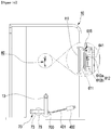
- a barbell position sensing device 420 for sensing a lowermost position of the barbell 41 is installed at a bottom end of the vertical bar 21a.
- a barbell contact piece 423 formed to protrude is pivotably mounted on the vertical bar to sense a contact when the barbell 41 is positioned at a lowermost point
- a position adjustor 425 is pivotably mounted on the end of the barbell contact piece 423.
- the position adjustor 425 passes through a bottom of the vertical bar and is inserted into a hole 638 formed at a bottom end of the pivoting bar 63 or released therefrom such that pivoting of the pivoting bar 63 may be restricted or be free.
- the position adjustor 425 has a structure in which an adjusting pin is inserted into a housing.
- a spring (not shown) is installed at the pin such that the position adjustor 425 is positioned to be constantly inserted into the hole 638 of the pivoting bar 63.
- the barbell portion 40 As a position of the barbell portion 40 is higher on the basis of a center of the fixing bearing portion 11, more force is necessary for adjusting the angle of the swing portion 20. On the other hand, as the position of the barbell portion 40 is lower, less force is necessary for adjusting the angle of the swing portion 20. Accordingly, the barbell portion 40 should be located at a lowermost end to adjust the angle with less force. Accordingly, when the barbell portion 40 is located at a top end, the barbell position sensing device 420 restricts the pivoting bar 63 not to move and the barbell portion 40 moves down to a bottom end to operate the barbell position sensing device 420 such that pivoting bar 63 may move.
- a barbell weight 90 is connected to the barbell portion 40 through a wire 91 to compensate a weight of the barbell portion 40.
- the wire 91 may disperse force through a plurality of upper pulleys or lower pulleys.
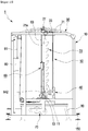
- a level 155 is installed below a center of the frame portion 10 such that it is possible to check whether the Smith machine is leveled with a bottom surface. That is, when the Smith machine is not leveled, it is possible to level the Smith machine by adjusting levelizers 150 installed at four corners of the frame portion 10.
- the levelizer 150 may have a structure for adjusting a height by spiral rotation.
- the level of the barbell 41 is finally adjustable through the level adjustment such that precise bilateral-symmetrical movement may be performed without a leaning phenomenon.
- a display device 85 is provided in an exact central portion of the rear of the frame portion 10 such that a front end of the bench 80 may be mounted on the display device. It is obvious to those skilled in the art that the display device 85 may be any component having a structure capable of displaying the exact center and may be variously changed.
- the swing portion 20 of the Smith machine 1 forms an angle of 90 degrees when the user lies on the bench 80.
- the pivoting bar 63 is located to coincide with the vertical bar 21a in parallel, and the fixing protrusion 273 of the angle adjustor 67 coupled to the operating rod 65 is completely inserted into the fixing groove 31 to be fixedly located.
- the user performs muscular movement by vertically moving the barbell 41 upward.
- the exercise may be performed by variously adjusting and then fixing the angle of the swing portion 20.
- the above-described angle adjustment of the swing portion 20 may be performed while the angle adjustor 67 is inserted into the fixing grooves 31 formed at the rail portion 30 according to a selection of the user.
- the user may exercise while the swing portion 20 is fixed.
- the user may exercise while the swing portion is freely movable within a certain range. That is, the swing portion 20 is freely movable according to an exercise path when the user moves the barbell 41 upward or downward.
- the user when the user wants to fix the swing portion 20 at a certain angle again, the user pulls the handle 611 of the main adjustor 61. Then, the stopper 615 rotates clockwise and returns to the original position due to the restoring force of the spring 619 connected thereto and releases the handle 611. Then, the handle 611 returns to the original position, and accordingly, the pivoting bar 63 also returns to the original position.
- the operating rod 65 moves, the fixing protrusion 273 of the angle adjustor 67 is inserted into another fixing groove 31 such that the swing portion 20 is fixed at a certain angle.
- the Smith machine according to the second embodiment of the present invention is a Smith machine used in an automatic mode generally using electricity.
- the Smith machine according to the second embodiment of the present invention is electrically embodied and significant components and operations thereof are similar or equal to the Smith machine according to the first embodiment of the present invention. Accordingly, like reference numerals refer to like elements and a detailed description on the like component will be omitted.
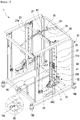
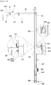
- a Smith machine 5 basically, pivots the swing portion 20 using a screw motor 400.
- the screw motor 400 is mounted on the frame portion 10, and a screw bar 401 connected to the screw motor 400 is connected to the swing portion 20.
- the screw bar 401 of the screw motor 400 linearly moves.
- the screw bar 401 is coupled to the compensating frame 73 of the swing portion compensating member 70. Accordingly, a length of the screw bar 401 is changed by an operation of the screw motor 400 such that the swing portion compensating member 70 pivots.
- the swing portion 20 pivots on the rail portion 30 forward or backward.
- a connecting device capable of selectively connecting or separating the screw motor 400 and the screw bar 401 to or from a bottom end of the swing portion may be further included.
- a height sensor portion 300 is perpendicularly installed at the swing portion 20 in a longitudinal direction to sense a height of the barbell. Accordingly, it is sensed that the height of the barbell 41 reaches a lowermost point, and the screw motor 400 is operated.
- the angle sensor portion 200 is installable on one side of the rail portion 30, and a plurality of sensors are attached to the angle sensor portion 200 to sense the angle of the swing portion 20.
- an electrical angle adjustor 670 may be additionally installed in a center of a top end of the horizontal bar 23 to be located to be adjacent to the rail portion 30, the electrical angle adjustor 670 is inserted into the fixing groove 31 of the rail portion 30 such that the swing portion 20 may be fixed.
- the electrical angle adjustor 670 may be a solenoid valve.
- the electrical angle adjustor 670 and the screw motor 400 operate in connection with each other at the same time due to an operation panel 500.
- the above-described electric Smith machine may be driven by the operation panel 500.
- the user may adjust the angle of the swing portion 20 through the operation panel 500.
- current height and angle of the barbell may be displayed on the operation panel in either the manual mode or the automatic mode.
- a connecting device 700 is mounted to easily connect or separate the screw motor to or from the bottom end of the swing portion and a sensor or switch is provided in the connecting device 700 such that a connection or separation state may be sensed. Accordingly, in the automatic mode, the screw motor and the electrical angle adjustor may be automatically operated through the operation panel 500.
- the connecting device 700 is released and the handle 611 is further pulled toward the user's body such that the second protrusion 612b of the handle 611 is separated from the fixing hole 614 of the stopper 615 and manual operation is available.
- an autonomous generator 690 is installed at any one selected from the plurality of pulleys which support the wire 91 which connects the barbell weight 90 such that electricity may be produced in normal rotation or reverse rotation of the pulley.
- a charger capable of applying external power may be mounted on the bottom of the frame portion.
- the above-mentioned produced electricity may be stored in a charged battery and may be used for operating the Smith machine. When the charged battery is exhausted, an external power source may be connected and used.
Landscapes
- Health & Medical Sciences (AREA)
- General Health & Medical Sciences (AREA)
- Physical Education & Sports Medicine (AREA)
- Life Sciences & Earth Sciences (AREA)
- Biophysics (AREA)
- Orthopedic Medicine & Surgery (AREA)
- Rehabilitation Tools (AREA)
- Orthopedics, Nursing, And Contraception (AREA)
Claims (14)
- Machine Smith à angle réglable et pouvant pivoter (1) comprenant :une partie bâti (10) qui forme un espace d'exercice ;une partie pivotante (20) disposée dans l'espace d'exercice et reliée à la partie bâti (10), la partie pivotante (20) comprenant des première et seconde barres verticales (21a, 21b) disposées à un intervalle, une barre horizontale (23) configurée pour relier des extrémités supérieures des première et seconde barres verticales (21a, 21b), et un élément de maintien (25) installé sur un côté de chacune des première et seconde barres verticales (21a, 21b) et comprenant une pluralité de parties concaves formées sur celui-ci ;une partie guide (50) reliée d'un seul tenant à la partie pivotante (20) pour pivoter avec celle-ci ;une partie rail (30) installée à une extrémité supérieure de la partie bâti (10) et configurée pour guider un mouvement de la partie pivotante (20) et comprenant une pluralité de rainures de fixation (31) formées sur au moins un côté de la partie rail (30) pour définir ou fixer un angle de la partie pivotante (20) ;une partie de réglage d'angle (60) pour régler l'angle de la partie pivotante (20) en liaison avec la partie rail (30) ; etune partie barre à disques (40) couplée à la partie guide (50) pour se déplacer vers le haut ou vers le bas,caractérisée par le fait quela partie pivotante (20) comprend en outre une partie rouleau de support (27) installée dans une extrémité supérieure de la barre horizontale (23) pour s'engager avec une extrémité supérieure de la partie rail (30) et configurée pour se déplacer le long de l'extrémité supérieure de la partie rail (30),la partie rail (30) est configurée pour relier un avant et un arrière de l'extrémité supérieure de la partie bâti (10), etla partie de réglage d'angle (60) comprend :un dispositif de réglage principal (61) installé sur un côté de la première barre verticale (21a) pour fonctionner lorsqu'un utilisateur règle l'angle de la partie pivotante (20),une barre pivotante (63) dont une partie inférieure est couplée de manière articulée à la première barre verticale (21a) et dont une partie supérieure pivote en fonction d'un mouvement du dispositif de réglage principal (61),une tige de commande (65) reliée à une extrémité supérieure de la barre pivotante (63) et installée sur la barre horizontale (23) tout en s'étendant vers la partie rail (30), etun dispositif de réglage d'angle (67) installé sur une extrémité de la tige de commande (65) et configuré pour être introduit dans l'une des rainures de fixation (31) en fonction d'un mouvement de translation de la tige de commande (65).
- Machine Smith à angle réglable et pouvant pivoter (1) selon la revendication 1,
dans laquelle une extrémité supérieure de la partie pivotante (20) est installée de manière pivotante pour être espacée de la partie bâti (10), et une extrémité inférieure de celle-ci est couplée de manière pivotante à une partie palier de fixation (11) installée sur un côté de la partie bâti (10),
la machine Smith (1) comprenant en outre un élément de compensation de partie pivotante (70) installé au-dessous d'un arbre rotatif (13) de la partie palier de fixation (11), l'élément de compensation de partie pivotante (70) comprenant un cadre de compensation (73) couplé à l'arbre rotatif (13) et une pluralité de poids de pivotement (75) couplés au cadre de compensation (73), et
le cadre de compensation (73) ayant une structure en forme de L qui est coudée dans une direction opposée à celle dans laquelle la partie barre à disques (40) est située, à savoir coudée vers un arrière de la machine Smith (1) . - Machine Smith à angle réglable et pouvant pivoter (1) selon la revendication 1, dans laquelle la partie rail (30) a une structure de plaque mince en forme d'arc qui partage un point central d'une partie palier de fixation (11), une fente longue (33) est formée dans une certaine plage basée sur une partie centrale de la partie rail (30), et la pluralité de rainures de fixation (31) sont formées sur la fente (33), et
un rouleau de la partie rouleau de support (27) comprend une rainure formée sur celui-ci, légèrement plus large qu'une épaisseur de la partie rail (30) pour s'engager avec l'extrémité supérieure de la partie rail (30) . - Machine Smith à angle réglable et pouvant pivoter (1) selon la revendication 1,
dans laquelle le dispositif de réglage d'angle (67) comprend un corps (271), une saillie de fixation (273) formée d'un seul tenant à une extrémité avant du corps (271), et une saillie libre (275) formée d'un seul tenant à une extrémité avant de la saillie de fixation (273), et
un diamètre de la saillie libre (275) étant plus petit qu'un diamètre de la saillie de fixation (273), et le diamètre de la saillie de fixation (273) ayant une taille capable d'être introduite dans les rainures de fixation (31) . - Machine Smith à angle réglable et pouvant pivoter (1) selon la revendication 1, dans laquelle le dispositif de réglage principal (61) comprend :une partie de préhension (613) reliée à la première barre verticale (21a) de la partie pivotante (20) ;une plaque de liaison (617) fixée à la barre pivotante (63) ;une poignée (611) disposée dans la partie de préhension (613) et couplée à la plaque de liaison (617) ;une butée (615) pour restreindre un actionnement de la poignée (611) ; etun ressort couplé à la butée (615) pour permettre à la butée (615) de retourner à une position initiale.
- Machine Smith à angle réglable et pouvant pivoter (1) selon la revendication 2, dans laquelle la partie barre à disques (40) comprend une longue barre à disques en forme de barre (41), une pièce maintenue (43) installée de manière fixe sur les deux côtés de la barre à disques (41) et maintenue par la partie concave (253) de l'élément de maintien (25) pour être placée sur celui-ci, et une plaque de liaison de barre à disques (45) pour accoupler la barre à disques (41) à la partie guide (50), et
un anneau d'indication circulaire (47) étant monté sur la barre à disques (41) pour indiquer des positions pour saisie avec les mains sur les côtés gauche et droit, sur la base d'une ligne centrale. - Machine Smith à angle réglable et pouvant pivoter (1) selon la revendication 6, comprenant en outre un dispositif de détection de position de barre à disques (420) installé à une extrémité inférieure de la première barre verticale (21a) pour détecter une position d'un point le plus bas de la barre à disques (41),
le dispositif de détection de position de barre à disques (420) comprenant :une pièce de contact de barre à disques (423) qui fait saillie pour détecter un contact lorsque la barre à disques (41) est située au point le plus bas et est montée de manière pivotante sur la première barre verticale (21a) ; etun dispositif de réglage de position (425) monté de manière pivotante sur l'autre extrémité de la pièce de contact de barre à disques (423) et capable de passer à travers la première barre verticale (21a) et être introduit dans ou séparé d'un trou (638) formé à une extrémité inférieure de la barre pivotante (63). - Machine Smith à angle réglable et pouvant pivoter (1) selon la revendication 6, comprenant en outre un poids de barre à disques (90) relié à la partie barre à disques (40) par l'intermédiaire d'un câble (91) pour compenser un poids de la partie barre à disques (40),
une poulie de réglage (95) étant installée pour être adjacente à la partie palier de fixation (11) et étant disposée de telle sorte qu'un point de courbure P entre une partie A et une partie B du câble (91), qui passe par la poulie de réglage (95), coïncide avec un point central d'un arbre rotatif (13) de la partie palier de fixation (11). - Machine Smith à angle réglable et pouvant pivoter (1) selon la revendication 6, dans laquelle un niveau (85) est installé sur un côté de la partie bâti (10) pour mettre la barre à disques (41) à niveau, et
des dispositifs de mise à niveau (150) sont installés à quatre coins de la partie bâti (10). - Machine Smith à angle réglable et pouvant pivoter (1) selon la revendication 1, comprenant en outre un dispositif d'affichage (85) installé dans une partie de centre exact d'un arrière de la partie bâti (10) pour placer un banc au centre exact de la machine Smith (1).
- Machine Smith à angle réglable et pouvant pivoter (1) selon la revendication 5, dans laquelle un trou de fixation (614) est formé dans un côté de la butée (615), et une broche en saillie (612) capable d'être introduite dans le trou de fixation (614) est formée d'un seul tenant au niveau de la poignée (611) dans son ensemble, et
la broche en saillie (612) comprenant une première saillie (612a) et une seconde saillie (612b), qui ont des longueurs différentes et sont montées de manière rotative pour changer de positions,
la machine Smith (1) comprenant en outre une tige de limitation de butée (641) couplée à la partie pivotante (20) et configurée pour restreindre ou libérer un pivotement de la butée (615), une pièce de fixation en forme de fer à cheval (642) comprenant une rainure concave (643) sur une extrémité supérieure de celle-ci pour déplacer la tige de limitation de la butée (615) vers le haut ou vers le bas, un ressort de traction (645) installé pour permettre à la tige de limitation de butée (641) d'avoir constamment une force pour se déplacer vers le bas, et une broche en saillie (617) formée pour faire saillie à partir de la butée (615) vers la tige de limitation de butée (641). - Machine Smith à angle réglable et pouvant pivoter (1) selon l'une quelconque des revendications 1 à 11, comprenant en outre un moteur à vis (400) et une tige filetée (401) reliée à des extrémités inférieures de la partie bâti (10) et de la partie pivotante (20) pour régler électriquement un angle de la partie pivotante (20), et un dispositif de liaison (700) capable, de manière sélective, de relier ou séparer le moteur à vis (400) et la tige filetée (401) à ou à partir de l'extrémité inférieure de la partie pivotante (20),
le dispositif de liaison (700) comprenant un capteur ou un commutateur à l'intérieur de celui-ci, pour détecter une liaison ou une séparation du moteur à vis (400) et de l'extrémité inférieure de la partie pivotante (20) . - Machine Smith à angle réglable et pouvant pivoter (1) selon la revendication 12, dans laquelle un dispositif de réglage d'angle électrique (670) est également installé pour être adjacent à la partie rail (30), et
une partie capteur d'angle (200) étant installée à l'extrémité supérieure de la partie rail (30), et
une partie capteur de hauteur (300) étant installée perpendiculairement à la partie pivotante (20) dans une direction longitudinale,
la machine Smith (1) comprenant un panneau de commande (500) sur une extrémité supérieure d'un côté gauche ou d'un côté droit d'une surface avant de la partie bâti (10) et configuré pour afficher une hauteur actuelle et un angle de la barre à disques (41). - Machine Smith à angle réglable et pouvant pivoter (1) selon la revendication 8, dans laquelle un générateur autonome (690) est installé à l'une quelconque choisie parmi les poulies qui supportent le câble (91), et un chargeur capable d'appliquer une puissance externe est monté au-dessous de la partie bâti (10).
Applications Claiming Priority (2)
| Application Number | Priority Date | Filing Date | Title |
|---|---|---|---|
| KR20150159887 | 2015-11-13 | ||
| PCT/KR2016/012903 WO2017082644A1 (fr) | 2015-11-13 | 2016-11-10 | Machine smith à angle réglable et pouvant pivoter |
Publications (3)
| Publication Number | Publication Date |
|---|---|
| EP3375496A1 EP3375496A1 (fr) | 2018-09-19 |
| EP3375496A4 EP3375496A4 (fr) | 2019-07-24 |
| EP3375496B1 true EP3375496B1 (fr) | 2021-04-14 |
Family
ID=59050601
Family Applications (1)
| Application Number | Title | Priority Date | Filing Date |
|---|---|---|---|
| EP16864570.3A Active EP3375496B1 (fr) | 2015-11-13 | 2016-11-10 | Machine smith à angle réglable et pouvant pivoter |
Country Status (7)
| Country | Link |
|---|---|
| US (1) | US10646740B2 (fr) |
| EP (1) | EP3375496B1 (fr) |
| JP (1) | JP6706410B2 (fr) |
| KR (1) | KR101858081B1 (fr) |
| CN (1) | CN108348802B (fr) |
| AU (1) | AU2016352500B2 (fr) |
| RU (1) | RU2683762C1 (fr) |
Families Citing this family (59)
| Publication number | Priority date | Publication date | Assignee | Title |
|---|---|---|---|---|
| US10864404B2 (en) * | 2016-02-02 | 2020-12-15 | Specialty Fitness Systems, Llc | Weight bench centering device |
| WO2018093699A1 (fr) * | 2016-11-15 | 2018-05-24 | Specialty Fitness Systems, Llc | Système de montée-descente de poulie pour machine à poids |
| US11660491B2 (en) | 2017-11-02 | 2023-05-30 | Coulter Ventures, Llc. | Weightlifting assembly |
| US11123595B2 (en) | 2017-11-02 | 2021-09-21 | Coulter Ventures, Llc. | Weightlifting rack assembly and wall mount bracket for a weightlifting rack assembly |
| USD890273S1 (en) * | 2018-07-11 | 2020-07-14 | Coulter Ventures, Llc. | Pair of J-cups |
| KR101940796B1 (ko) * | 2018-03-16 | 2019-01-22 | 주식회사 동아스포츠 | 웨이트 운동기구 |
| KR102004656B1 (ko) * | 2018-05-10 | 2019-07-26 | 이병돈 | 각도조절 및 스윙 가능한 스미스 머신 |
| KR20190132754A (ko) | 2018-05-21 | 2019-11-29 | 이승민 | 안정장치가 결합된 스미스머신 |
| USD886920S1 (en) | 2018-06-05 | 2020-06-09 | Coulter Ventures, Llc. | Set of wall mounts for exercise rack |
| USD888851S1 (en) | 2018-06-05 | 2020-06-30 | Coulter Ventures, Llc. | Wall mounted exercise rack |
| USD883405S1 (en) * | 2018-06-05 | 2020-05-05 | Coulter Ventures, Llc. | Wall mounted exercise rack |
| USD879216S1 (en) * | 2018-06-05 | 2020-03-24 | Coulter Ventures, Llc. | Wall mount |
| USD929512S1 (en) | 2018-06-05 | 2021-08-31 | Coulter Ventures, Llc. | Wall mount for pull up bar |
| US10695602B2 (en) * | 2018-07-18 | 2020-06-30 | Recreation Supply, Inc. | Exercise machine |
| KR102077615B1 (ko) | 2018-09-03 | 2020-02-14 | 경북대학교 산학협력단 | 자동 제어 방식 운동 보조 장치 및 제어 방법, 상기 방법을 수행하기 위한 기록 매체 |
| KR102092308B1 (ko) | 2018-09-03 | 2020-03-23 | 충남대학교산학협력단 | 안전성이 강화된 스미스 머신 |
| CN109107097B (zh) * | 2018-09-10 | 2020-10-20 | 王芊蔚 | 一种多维度健腹机 |
| US11389690B2 (en) * | 2018-09-13 | 2022-07-19 | Kondition, Inc. | Multi-use fitness machine and methods of use |
| CN108969976B (zh) * | 2018-10-08 | 2020-11-24 | 惠安豪行优运科技有限公司 | 一种体育杠铃锻炼设备 |
| USD956893S1 (en) | 2020-10-13 | 2022-07-05 | Coulter Ventures, Llc. | Seat assembly for weightlifting apparatus |
| AU2019357057B2 (en) | 2018-10-12 | 2023-02-02 | Coulter Ventures, LLC | Weightlifting machine |
| US12036436B2 (en) | 2018-10-12 | 2024-07-16 | Coulter Ventures, Llc. | Weightlifting machine |
| WO2020081171A1 (fr) * | 2018-10-17 | 2020-04-23 | Hoist Fitness Systems, Inc. | Ensemble poignée de préhension à position réglable pour machines d'exercice |
| CN121314143A (zh) * | 2018-10-18 | 2026-01-13 | 曲线日本株式会社 | 伸展用运动器具 |
| KR101983783B1 (ko) * | 2018-11-30 | 2019-05-30 | 주식회사 서창테크 | 다양한 구종 및 구질을 구현 가능한 피칭 머신 |
| KR200492035Y1 (ko) | 2019-01-29 | 2020-07-23 | 최원진 | 기능성 바벨 거치대 |
| CN109701245B (zh) * | 2019-02-20 | 2020-07-07 | 高一博 | 一种安全防摔杠铃架 |
| US11235192B1 (en) * | 2019-04-11 | 2022-02-01 | Zhair Giovanni Thomas | Exercise apparatus |
| WO2020230932A1 (fr) * | 2019-05-16 | 2020-11-19 | 이병돈 | Machine smith capable de régler et d'osciller un angle |
| CN110465042B (zh) * | 2019-09-26 | 2025-05-13 | 山东力之星健身科技有限公司 | 多方位训练器 |
| KR102714191B1 (ko) * | 2019-12-19 | 2024-10-07 | 에스엘 주식회사 | 차량 제어 시스템 |
| USD942561S1 (en) | 2020-02-07 | 2022-02-01 | Coulter Ventures, Llc. | Mounting assembly for a weight rack |
| KR20210101523A (ko) | 2020-02-10 | 2021-08-19 | 정승원 | 사선형 스미스 머신 |
| USD955509S1 (en) | 2020-04-06 | 2022-06-21 | Coulter Ventures, Llc. | Wall mount for an exercise rack |
| IT202000008707A1 (it) * | 2020-04-23 | 2021-10-23 | Stefano Cristofanelli | Macchina ginnica per il sollevamento pesi |
| USD952069S1 (en) | 2020-04-29 | 2022-05-17 | Coulter Ventures, Llc. | Wall mounted weight rack |
| CN112206474A (zh) * | 2020-08-28 | 2021-01-12 | 江苏福维健康科技有限公司 | 一种卧推架结构 |
| CN112535837A (zh) * | 2020-11-25 | 2021-03-23 | 郑永金 | 一种发电用坐式举重装置 |
| CN112619032A (zh) * | 2020-12-17 | 2021-04-09 | 浙江工业职业技术学院 | 一种带保护装置的史密斯健身架 |
| USD1007619S1 (en) | 2020-12-23 | 2023-12-12 | Coulter Ventures, Llc. | Wall mount for exercise rack |
| USD1037839S1 (en) | 2021-01-28 | 2024-08-06 | Coulter Ventures, Llc. | Wall mount bracket |
| CN117098580A (zh) | 2021-03-09 | 2023-11-21 | 科迪·奥斯汀·拉尼尔 | 马达驱动的升降架系统 |
| KR102337665B1 (ko) * | 2021-07-21 | 2021-12-09 | 주식회사 디지웨이트 | 다양한 바벨운동이 가능한 헬스 운동장치 |
| AU2022341039A1 (en) * | 2021-08-31 | 2024-04-18 | Josef Patrick Krouzecky | Demountable exercising apparatus |
| USD980354S1 (en) * | 2021-10-29 | 2023-03-07 | Xavork Wooliand Inc | Fitness equipment |
| US12239873B2 (en) * | 2022-01-28 | 2025-03-04 | Cody D. Rees | Weight elevation systems, methods, and devices |
| KR102432832B1 (ko) | 2022-02-15 | 2022-08-12 | 윤순용 | 바벨봉이 분리된 스미스 머신 |
| CN115068882B (zh) * | 2022-06-16 | 2023-07-14 | 华北理工大学 | 一种体育锻炼教学用具及其使用方法 |
| US12350541B1 (en) | 2022-07-14 | 2025-07-08 | Hypertrophy Tech LLC | System and methods for facilitating the use of a weight press machine |
| CN119677564B (zh) | 2022-08-04 | 2025-11-04 | 豪埃斯特健康体系股份有限公司 | 具有选择性阻力的双重作用举重机 |
| US12383783B2 (en) | 2022-08-04 | 2025-08-12 | Hoist Fitness Systems, Inc. | Dual action weightlifting machine with selectorized resistance |
| WO2024145080A1 (fr) * | 2022-12-28 | 2024-07-04 | Hoist Fitness Systems, Inc. | Machine smith ayant des composants réversibles qui font varier l'angle de levage de la machine |
| US12569714B2 (en) * | 2023-03-16 | 2026-03-10 | Bulletproof Fitness Equipment Inc | Tilting smith exercise machine with movable structures |
| USD1026127S1 (en) * | 2023-06-07 | 2024-05-07 | Shaowei Tong | Exercise equipment |
| USD1017735S1 (en) * | 2023-06-08 | 2024-03-12 | Shaowei Tong | Exercise equipment |
| USD1018726S1 (en) * | 2023-06-27 | 2024-03-19 | Qiongfang Mao | Exercise equipment |
| WO2025096665A1 (fr) * | 2023-10-30 | 2025-05-08 | Gym Rax International, Inc. | Machine smith |
| USD1109826S1 (en) | 2024-02-16 | 2026-01-20 | Coulter Ventures, Llc. | Weightlifting assembly |
| JP7849933B1 (ja) | 2025-07-28 | 2026-04-22 | 株式会社Oni | スミスマシン |
Family Cites Families (41)
| Publication number | Priority date | Publication date | Assignee | Title |
|---|---|---|---|---|
| US3359802A (en) * | 1964-05-08 | 1967-12-26 | Carl E Sollenberger | Apparatus for bar-bell type exercises |
| US3451271A (en) * | 1966-06-30 | 1969-06-24 | David E Knoblauch | Hydraulically controlled exercising and weight lifting device |
| US3606318A (en) * | 1969-07-03 | 1971-09-20 | James B Gilstrap | Fluid resistant type exercising device |
| US4286782A (en) * | 1978-10-26 | 1981-09-01 | Fuhrhop Marious P | Multi-purpose exercise enhancing device |
| JPS57139359U (fr) * | 1981-02-26 | 1982-08-31 | ||
| CA1288790C (fr) * | 1985-08-30 | 1991-09-10 | William Palahnuk | Dispositif plurivalent d'exercise physique |
| US4784384A (en) * | 1986-01-06 | 1988-11-15 | Deola James A | Weightlifting exercise device |
| US4856773A (en) * | 1987-05-22 | 1989-08-15 | Deola James A | Weightlifting exercise device |
| US5044629A (en) * | 1989-04-06 | 1991-09-03 | Stephen Ryan | Wheelchair accessible weight training apparatus |
| US5135453A (en) * | 1989-09-27 | 1992-08-04 | Sollenberger Carl E | Exercise apparatus for performing free weight barbell exercise |
| US5018725A (en) * | 1990-07-25 | 1991-05-28 | Cook Roger D | Adjustable exercise equipment |
| US5215510A (en) * | 1991-09-16 | 1993-06-01 | John Baran | Dual-guided exercise apparatus |
| US5669859A (en) * | 1995-11-21 | 1997-09-23 | Rack Max Inc | Weightlifting apparatus |
| US6120424A (en) * | 1997-08-22 | 2000-09-19 | Arline; Clayton | Body building apparatus |
| US6379287B1 (en) * | 1998-11-30 | 2002-04-30 | Prospot, Inc. | Barbell and dumbbell safety spotting apparatus |
| US6245000B1 (en) * | 1999-08-19 | 2001-06-12 | Anna Saakian | Exercise device and body toner with adjustable inclined roller platform |
| US6293892B1 (en) * | 1999-08-28 | 2001-09-25 | Prospot, Inc. | Self-spotting apparatus for free-weights |
| IT1314170B1 (it) * | 1999-10-05 | 2002-12-04 | Giuseppe Musso | Attrezzo sportivo che durante l'esercizio segue la naturaletraiettoria fisiologica di ciascun individuo. |
| US6450927B1 (en) * | 2000-11-03 | 2002-09-17 | Northland Industries, Inc. | Pivoting weight rack |
| US7488277B1 (en) * | 2000-11-17 | 2009-02-10 | Knapp Jeffrey M | Compact weightlifting frame system |
| US20020091043A1 (en) | 2000-12-20 | 2002-07-11 | Rexach Marco L. | Space efficient multi-use exercise apparatus |
| JP2004201943A (ja) * | 2002-12-25 | 2004-07-22 | Sakai Medical Co Ltd | 身体訓練装置 |
| US7591770B2 (en) * | 2003-06-18 | 2009-09-22 | Precor Incorporated | Press station with add-on weights |
| FR2881355A1 (fr) * | 2005-02-03 | 2006-08-04 | Guillaume Rolland | Appareil de musculation et/ou de reeducation |
| JP2007029329A (ja) * | 2005-07-26 | 2007-02-08 | Upsen:Kk | トレーニングマシーン |
| US7374516B2 (en) * | 2005-08-19 | 2008-05-20 | Recreation Supply, Inc. | Weight lifting power cage with slave rack |
| US7393309B2 (en) * | 2006-02-28 | 2008-07-01 | Webber Randall T | Dual action weightlifting machine |
| US8328698B1 (en) * | 2006-02-28 | 2012-12-11 | Hoist Fitness Systems, Inc. | Exercise bar assembly for dual action weightlifting machine |
| US7635322B2 (en) * | 2007-11-27 | 2009-12-22 | Marco Parrilla | Squat rack |
| US8727946B2 (en) * | 2010-05-06 | 2014-05-20 | Smalley Steel Ring Company | Spotting device |
| KR101315514B1 (ko) * | 2012-10-19 | 2013-10-07 | 이주희 | 수직식 전신 운동기구 |
| US8740760B2 (en) * | 2012-11-05 | 2014-06-03 | Ryan John York | Pivoting twin arm support for free weights |
| US8834329B2 (en) * | 2013-01-02 | 2014-09-16 | Sean Kelly | Bench press combining full body safety bars and gliding bar holder arms |
| US8900097B1 (en) * | 2013-03-15 | 2014-12-02 | Omegamax Holding Company, LLC | Apparatus and method for delivery of assistive force to user moved weights |
| CA2850734C (fr) * | 2013-06-11 | 2022-07-12 | Dream Visions, Llc. | Appareil d'exercice |
| JP2015012988A (ja) * | 2013-07-05 | 2015-01-22 | 酒井医療株式会社 | 運動用器具 |
| CN203852792U (zh) * | 2014-04-17 | 2014-10-01 | 华北电力大学 | 一种气缸卧推史密斯架 |
| CN105080041A (zh) | 2014-05-08 | 2015-11-25 | 青岛瑞箭机电工程技术有限公司 | 臂肌力量练习器 |
| KR101518197B1 (ko) * | 2015-02-09 | 2015-05-15 | 서정근 | 웨이트 운동기구 |
| US10245461B2 (en) * | 2016-03-16 | 2019-04-02 | Dave Peter Bruni | Strength training system and method of using same |
| CN106139512A (zh) | 2016-08-12 | 2016-11-23 | 天津市兴凯体育器械有限公司 | 一种稳定、防滑的史密斯架 |
-
2016
- 2016-11-10 KR KR1020160149279A patent/KR101858081B1/ko not_active Expired - Fee Related
- 2016-11-10 US US15/774,594 patent/US10646740B2/en not_active Expired - Fee Related
- 2016-11-10 JP JP2018525427A patent/JP6706410B2/ja not_active Expired - Fee Related
- 2016-11-10 RU RU2018120881A patent/RU2683762C1/ru active
- 2016-11-10 EP EP16864570.3A patent/EP3375496B1/fr active Active
- 2016-11-10 AU AU2016352500A patent/AU2016352500B2/en not_active Ceased
- 2016-11-10 CN CN201680065281.6A patent/CN108348802B/zh not_active Expired - Fee Related
Non-Patent Citations (1)
| Title |
|---|
| None * |
Also Published As
| Publication number | Publication date |
|---|---|
| US20180318635A1 (en) | 2018-11-08 |
| RU2683762C1 (ru) | 2019-04-01 |
| AU2016352500A1 (en) | 2018-05-31 |
| JP6706410B2 (ja) | 2020-06-10 |
| EP3375496A1 (fr) | 2018-09-19 |
| AU2016352500B2 (en) | 2020-01-23 |
| KR20170056449A (ko) | 2017-05-23 |
| EP3375496A4 (fr) | 2019-07-24 |
| US10646740B2 (en) | 2020-05-12 |
| CN108348802A (zh) | 2018-07-31 |
| CN108348802B (zh) | 2020-02-11 |
| KR101858081B1 (ko) | 2018-05-15 |
| JP2018537171A (ja) | 2018-12-20 |
Similar Documents
| Publication | Publication Date | Title |
|---|---|---|
| EP3375496B1 (fr) | Machine smith à angle réglable et pouvant pivoter | |
| CA2216740C (fr) | Appareil d'evaluation des muscles cervicaux | |
| DK2723456T3 (en) | SUPPORTED BODY WEIGHT EXERCISE WITH ADJUSTABLE CHIN-UPS / PULL-UPS-GREB | |
| US7322906B2 (en) | Exercise arm assembly for exercise machine | |
| US8317668B2 (en) | Exercise device for abdominal and other core muscles | |
| US20080004166A1 (en) | Compact office exercise unit | |
| WO2006044013A2 (fr) | Dispositif d'exercice a tige allongee flexible unique et controle de selecteur de poids | |
| US20170056728A1 (en) | Exercise balance trainer | |
| CA3112238C (fr) | Machine d'exercice de compression de fessier | |
| US11135463B2 (en) | Motor-driven variable weight exercise device with modular chassis body | |
| US6860840B2 (en) | Exercise machine for exercising upper body portions | |
| US20150038301A1 (en) | Core Exercise Apparatus and Methods | |
| US20240139577A1 (en) | Training device | |
| US20130267391A1 (en) | Core Exercise Apparatus and Methods | |
| KR102163557B1 (ko) | 근력측정장치 | |
| KR20230153121A (ko) | 모터제어식 스마트 피트니스 머신 | |
| EP0045660B1 (fr) | Appareil simulateur de coups de canne de golf | |
| CN113926138A (zh) | 一种基于3d扫描的个性化全身综合训练器 | |
| CN218740045U (zh) | 一种重量可调节的杠铃 | |
| KR102619378B1 (ko) | 헬스기구용 중량조절장치 | |
| CN221061636U (zh) | 一种带有辅助支撑杆的家用踏步机 | |
| KR102645853B1 (ko) | 드롭 스쿼트 머신 | |
| KR20060028230A (ko) | 체성분 측정기 및 그 측정방법 | |
| WO2017082644A1 (fr) | Machine smith à angle réglable et pouvant pivoter | |
| US12145019B2 (en) | Workout equipment |
Legal Events
| Date | Code | Title | Description |
|---|---|---|---|
| STAA | Information on the status of an ep patent application or granted ep patent |
Free format text: STATUS: THE INTERNATIONAL PUBLICATION HAS BEEN MADE |
|
| PUAI | Public reference made under article 153(3) epc to a published international application that has entered the european phase |
Free format text: ORIGINAL CODE: 0009012 |
|
| STAA | Information on the status of an ep patent application or granted ep patent |
Free format text: STATUS: REQUEST FOR EXAMINATION WAS MADE |
|
| 17P | Request for examination filed |
Effective date: 20180611 |
|
| AK | Designated contracting states |
Kind code of ref document: A1 Designated state(s): AL AT BE BG CH CY CZ DE DK EE ES FI FR GB GR HR HU IE IS IT LI LT LU LV MC MK MT NL NO PL PT RO RS SE SI SK SM TR |
|
| AX | Request for extension of the european patent |
Extension state: BA ME |
|
| DAV | Request for validation of the european patent (deleted) | ||
| DAX | Request for extension of the european patent (deleted) | ||
| A4 | Supplementary search report drawn up and despatched |
Effective date: 20190625 |
|
| RIC1 | Information provided on ipc code assigned before grant |
Ipc: A63B 21/00 20060101ALI20190618BHEP Ipc: A63B 21/078 20060101ALI20190618BHEP Ipc: A63B 21/072 20060101AFI20190618BHEP |
|
| GRAP | Despatch of communication of intention to grant a patent |
Free format text: ORIGINAL CODE: EPIDOSNIGR1 |
|
| STAA | Information on the status of an ep patent application or granted ep patent |
Free format text: STATUS: GRANT OF PATENT IS INTENDED |
|
| INTG | Intention to grant announced |
Effective date: 20201111 |
|
| GRAS | Grant fee paid |
Free format text: ORIGINAL CODE: EPIDOSNIGR3 |
|
| GRAA | (expected) grant |
Free format text: ORIGINAL CODE: 0009210 |
|
| STAA | Information on the status of an ep patent application or granted ep patent |
Free format text: STATUS: THE PATENT HAS BEEN GRANTED |
|
| AK | Designated contracting states |
Kind code of ref document: B1 Designated state(s): AL AT BE BG CH CY CZ DE DK EE ES FI FR GB GR HR HU IE IS IT LI LT LU LV MC MK MT NL NO PL PT RO RS SE SI SK SM TR |
|
| REG | Reference to a national code |
Ref country code: GB Ref legal event code: FG4D |
|
| REG | Reference to a national code |
Ref country code: CH Ref legal event code: EP |
|
| REG | Reference to a national code |
Ref country code: DE Ref legal event code: R096 Ref document number: 602016056253 Country of ref document: DE |
|
| REG | Reference to a national code |
Ref country code: IE Ref legal event code: FG4D |
|
| REG | Reference to a national code |
Ref country code: AT Ref legal event code: REF Ref document number: 1381773 Country of ref document: AT Kind code of ref document: T Effective date: 20210515 |
|
| REG | Reference to a national code |
Ref country code: LT Ref legal event code: MG9D |
|
| REG | Reference to a national code |
Ref country code: AT Ref legal event code: MK05 Ref document number: 1381773 Country of ref document: AT Kind code of ref document: T Effective date: 20210414 |
|
| REG | Reference to a national code |
Ref country code: NL Ref legal event code: MP Effective date: 20210414 |
|
| PG25 | Lapsed in a contracting state [announced via postgrant information from national office to epo] |
Ref country code: NL Free format text: LAPSE BECAUSE OF FAILURE TO SUBMIT A TRANSLATION OF THE DESCRIPTION OR TO PAY THE FEE WITHIN THE PRESCRIBED TIME-LIMIT Effective date: 20210414 Ref country code: BG Free format text: LAPSE BECAUSE OF FAILURE TO SUBMIT A TRANSLATION OF THE DESCRIPTION OR TO PAY THE FEE WITHIN THE PRESCRIBED TIME-LIMIT Effective date: 20210714 Ref country code: AT Free format text: LAPSE BECAUSE OF FAILURE TO SUBMIT A TRANSLATION OF THE DESCRIPTION OR TO PAY THE FEE WITHIN THE PRESCRIBED TIME-LIMIT Effective date: 20210414 Ref country code: HR Free format text: LAPSE BECAUSE OF FAILURE TO SUBMIT A TRANSLATION OF THE DESCRIPTION OR TO PAY THE FEE WITHIN THE PRESCRIBED TIME-LIMIT Effective date: 20210414 Ref country code: LT Free format text: LAPSE BECAUSE OF FAILURE TO SUBMIT A TRANSLATION OF THE DESCRIPTION OR TO PAY THE FEE WITHIN THE PRESCRIBED TIME-LIMIT Effective date: 20210414 Ref country code: FI Free format text: LAPSE BECAUSE OF FAILURE TO SUBMIT A TRANSLATION OF THE DESCRIPTION OR TO PAY THE FEE WITHIN THE PRESCRIBED TIME-LIMIT Effective date: 20210414 |
|
| PG25 | Lapsed in a contracting state [announced via postgrant information from national office to epo] |
Ref country code: GR Free format text: LAPSE BECAUSE OF FAILURE TO SUBMIT A TRANSLATION OF THE DESCRIPTION OR TO PAY THE FEE WITHIN THE PRESCRIBED TIME-LIMIT Effective date: 20210715 Ref country code: LV Free format text: LAPSE BECAUSE OF FAILURE TO SUBMIT A TRANSLATION OF THE DESCRIPTION OR TO PAY THE FEE WITHIN THE PRESCRIBED TIME-LIMIT Effective date: 20210414 Ref country code: IS Free format text: LAPSE BECAUSE OF FAILURE TO SUBMIT A TRANSLATION OF THE DESCRIPTION OR TO PAY THE FEE WITHIN THE PRESCRIBED TIME-LIMIT Effective date: 20210814 Ref country code: SE Free format text: LAPSE BECAUSE OF FAILURE TO SUBMIT A TRANSLATION OF THE DESCRIPTION OR TO PAY THE FEE WITHIN THE PRESCRIBED TIME-LIMIT Effective date: 20210414 Ref country code: RS Free format text: LAPSE BECAUSE OF FAILURE TO SUBMIT A TRANSLATION OF THE DESCRIPTION OR TO PAY THE FEE WITHIN THE PRESCRIBED TIME-LIMIT Effective date: 20210414 Ref country code: NO Free format text: LAPSE BECAUSE OF FAILURE TO SUBMIT A TRANSLATION OF THE DESCRIPTION OR TO PAY THE FEE WITHIN THE PRESCRIBED TIME-LIMIT Effective date: 20210714 Ref country code: PT Free format text: LAPSE BECAUSE OF FAILURE TO SUBMIT A TRANSLATION OF THE DESCRIPTION OR TO PAY THE FEE WITHIN THE PRESCRIBED TIME-LIMIT Effective date: 20210816 Ref country code: PL Free format text: LAPSE BECAUSE OF FAILURE TO SUBMIT A TRANSLATION OF THE DESCRIPTION OR TO PAY THE FEE WITHIN THE PRESCRIBED TIME-LIMIT Effective date: 20210414 |
|
| REG | Reference to a national code |
Ref country code: DE Ref legal event code: R097 Ref document number: 602016056253 Country of ref document: DE |
|
| PG25 | Lapsed in a contracting state [announced via postgrant information from national office to epo] |
Ref country code: RO Free format text: LAPSE BECAUSE OF FAILURE TO SUBMIT A TRANSLATION OF THE DESCRIPTION OR TO PAY THE FEE WITHIN THE PRESCRIBED TIME-LIMIT Effective date: 20210414 Ref country code: ES Free format text: LAPSE BECAUSE OF FAILURE TO SUBMIT A TRANSLATION OF THE DESCRIPTION OR TO PAY THE FEE WITHIN THE PRESCRIBED TIME-LIMIT Effective date: 20210414 Ref country code: CZ Free format text: LAPSE BECAUSE OF FAILURE TO SUBMIT A TRANSLATION OF THE DESCRIPTION OR TO PAY THE FEE WITHIN THE PRESCRIBED TIME-LIMIT Effective date: 20210414 Ref country code: DK Free format text: LAPSE BECAUSE OF FAILURE TO SUBMIT A TRANSLATION OF THE DESCRIPTION OR TO PAY THE FEE WITHIN THE PRESCRIBED TIME-LIMIT Effective date: 20210414 Ref country code: EE Free format text: LAPSE BECAUSE OF FAILURE TO SUBMIT A TRANSLATION OF THE DESCRIPTION OR TO PAY THE FEE WITHIN THE PRESCRIBED TIME-LIMIT Effective date: 20210414 Ref country code: SM Free format text: LAPSE BECAUSE OF FAILURE TO SUBMIT A TRANSLATION OF THE DESCRIPTION OR TO PAY THE FEE WITHIN THE PRESCRIBED TIME-LIMIT Effective date: 20210414 Ref country code: SK Free format text: LAPSE BECAUSE OF FAILURE TO SUBMIT A TRANSLATION OF THE DESCRIPTION OR TO PAY THE FEE WITHIN THE PRESCRIBED TIME-LIMIT Effective date: 20210414 |
|
| PGFP | Annual fee paid to national office [announced via postgrant information from national office to epo] |
Ref country code: GB Payment date: 20211118 Year of fee payment: 6 Ref country code: DE Payment date: 20211126 Year of fee payment: 6 Ref country code: FR Payment date: 20211117 Year of fee payment: 6 |
|
| PLBE | No opposition filed within time limit |
Free format text: ORIGINAL CODE: 0009261 |
|
| STAA | Information on the status of an ep patent application or granted ep patent |
Free format text: STATUS: NO OPPOSITION FILED WITHIN TIME LIMIT |
|
| PGFP | Annual fee paid to national office [announced via postgrant information from national office to epo] |
Ref country code: IT Payment date: 20211122 Year of fee payment: 6 |
|
| 26N | No opposition filed |
Effective date: 20220117 |
|
| PG25 | Lapsed in a contracting state [announced via postgrant information from national office to epo] |
Ref country code: IS Free format text: LAPSE BECAUSE OF FAILURE TO SUBMIT A TRANSLATION OF THE DESCRIPTION OR TO PAY THE FEE WITHIN THE PRESCRIBED TIME-LIMIT Effective date: 20210814 Ref country code: AL Free format text: LAPSE BECAUSE OF FAILURE TO SUBMIT A TRANSLATION OF THE DESCRIPTION OR TO PAY THE FEE WITHIN THE PRESCRIBED TIME-LIMIT Effective date: 20210414 |
|
| PG25 | Lapsed in a contracting state [announced via postgrant information from national office to epo] |
Ref country code: MC Free format text: LAPSE BECAUSE OF FAILURE TO SUBMIT A TRANSLATION OF THE DESCRIPTION OR TO PAY THE FEE WITHIN THE PRESCRIBED TIME-LIMIT Effective date: 20210414 |
|
| REG | Reference to a national code |
Ref country code: CH Ref legal event code: PL |
|
| PG25 | Lapsed in a contracting state [announced via postgrant information from national office to epo] |
Ref country code: LU Free format text: LAPSE BECAUSE OF NON-PAYMENT OF DUE FEES Effective date: 20211110 Ref country code: BE Free format text: LAPSE BECAUSE OF NON-PAYMENT OF DUE FEES Effective date: 20211130 |
|
| REG | Reference to a national code |
Ref country code: BE Ref legal event code: MM Effective date: 20211130 |
|
| PG25 | Lapsed in a contracting state [announced via postgrant information from national office to epo] |
Ref country code: IE Free format text: LAPSE BECAUSE OF NON-PAYMENT OF DUE FEES Effective date: 20211110 |
|
| PG25 | Lapsed in a contracting state [announced via postgrant information from national office to epo] |
Ref country code: HU Free format text: LAPSE BECAUSE OF FAILURE TO SUBMIT A TRANSLATION OF THE DESCRIPTION OR TO PAY THE FEE WITHIN THE PRESCRIBED TIME-LIMIT; INVALID AB INITIO Effective date: 20161110 |
|
| REG | Reference to a national code |
Ref country code: DE Ref legal event code: R119 Ref document number: 602016056253 Country of ref document: DE |
|
| PG25 | Lapsed in a contracting state [announced via postgrant information from national office to epo] |
Ref country code: CY Free format text: LAPSE BECAUSE OF FAILURE TO SUBMIT A TRANSLATION OF THE DESCRIPTION OR TO PAY THE FEE WITHIN THE PRESCRIBED TIME-LIMIT Effective date: 20210414 |
|
| GBPC | Gb: european patent ceased through non-payment of renewal fee |
Effective date: 20221110 |
|
| PG25 | Lapsed in a contracting state [announced via postgrant information from national office to epo] |
Ref country code: LI Free format text: LAPSE BECAUSE OF NON-PAYMENT OF DUE FEES Effective date: 20220630 Ref country code: CH Free format text: LAPSE BECAUSE OF NON-PAYMENT OF DUE FEES Effective date: 20220630 |
|
| PG25 | Lapsed in a contracting state [announced via postgrant information from national office to epo] |
Ref country code: IT Free format text: LAPSE BECAUSE OF NON-PAYMENT OF DUE FEES Effective date: 20221110 Ref country code: GB Free format text: LAPSE BECAUSE OF NON-PAYMENT OF DUE FEES Effective date: 20221110 Ref country code: DE Free format text: LAPSE BECAUSE OF NON-PAYMENT OF DUE FEES Effective date: 20230601 |
|
| PG25 | Lapsed in a contracting state [announced via postgrant information from national office to epo] |
Ref country code: FR Free format text: LAPSE BECAUSE OF NON-PAYMENT OF DUE FEES Effective date: 20221130 |
|
| PG25 | Lapsed in a contracting state [announced via postgrant information from national office to epo] |
Ref country code: MK Free format text: LAPSE BECAUSE OF FAILURE TO SUBMIT A TRANSLATION OF THE DESCRIPTION OR TO PAY THE FEE WITHIN THE PRESCRIBED TIME-LIMIT Effective date: 20210414 |
|
| PG25 | Lapsed in a contracting state [announced via postgrant information from national office to epo] |
Ref country code: TR Free format text: LAPSE BECAUSE OF FAILURE TO SUBMIT A TRANSLATION OF THE DESCRIPTION OR TO PAY THE FEE WITHIN THE PRESCRIBED TIME-LIMIT Effective date: 20210414 |
|
| PG25 | Lapsed in a contracting state [announced via postgrant information from national office to epo] |
Ref country code: MT Free format text: LAPSE BECAUSE OF FAILURE TO SUBMIT A TRANSLATION OF THE DESCRIPTION OR TO PAY THE FEE WITHIN THE PRESCRIBED TIME-LIMIT Effective date: 20210414 |