EP3375551A1 - Pendelhalter mit einstellbarem radialspiel - Google Patents
Pendelhalter mit einstellbarem radialspiel Download PDFInfo
- Publication number
- EP3375551A1 EP3375551A1 EP18000253.7A EP18000253A EP3375551A1 EP 3375551 A1 EP3375551 A1 EP 3375551A1 EP 18000253 A EP18000253 A EP 18000253A EP 3375551 A1 EP3375551 A1 EP 3375551A1
- Authority
- EP
- European Patent Office
- Prior art keywords
- holder
- tool
- coupling
- pendulum
- machine
- Prior art date
- Legal status (The legal status is an assumption and is not a legal conclusion. Google has not performed a legal analysis and makes no representation as to the accuracy of the status listed.)
- Granted
Links
Images
Classifications
-
- B—PERFORMING OPERATIONS; TRANSPORTING
- B23—MACHINE TOOLS; METAL-WORKING NOT OTHERWISE PROVIDED FOR
- B23B—TURNING; BORING
- B23B31/00—Chucks; Expansion mandrels; Adaptations thereof for remote control
- B23B31/02—Chucks
- B23B31/08—Chucks holding tools yieldably
Definitions
- the invention relates to a pendulum holder according to the preamble of claim 1.
- the invention has the object of developing a generic pendulum holder to the effect that the possible means of the pendulum holder radial clearance is precisely adjustable to a defined maximum value.
- the invention proposes, in other words, not to arrange an elastic element between the two radial play permitting coupling elements, which allows a different size radial clearance depending on the bias, but rather an oblique surface is provided on one of the two coupling elements and an adjustability of the two coupling elements against each other in that the inclined surface, depending on the relative position, which the occupy two coupling elements to each other, occupies a different sized effective distance to the respective other coupling element.
- the radial play is precisely defined by the gap width of the annular gap, which is set between the two coupling elements.
- the oblique surface extends circumferentially about the central axis of the pendulum holder, so that the effective gap width and thus the radial clearance of the pendulum holder can be adjusted by a rotational movement of the two coupling elements relative to each other.
- the adjustability of the two coupling elements against each other by means of a screw thread can be realized.
- the thread pitch can be achieved by a comparatively large displacement, namely in the circumference direction, a comparatively small displacement in the axial direction be so that a particularly sensitive and accurate adjustment of the desired radial clearance is possible.
- the radial clearance does not result directly from the distance between the two coupling elements, but rather the annular gap between the two coupling elements is sized so large that the bearing body are received therein and rather the remaining then Free gap width determines the radial play of the pendulum holder.
- the bearing body can be configured as balls. Due to their small contact surface, they enable on the one hand a particularly smooth running of the pendulum holder and, moreover, such bearing bodies are commercially available and thus very economical and very precise as far as their dimensions are concerned.
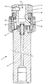
- a total of a tool holder is shown, which is referred to as a pendulum holder and having a machine holder 2 and a tool holder 3.
- the tool holder 3 has a receiving opening 4 into which a tool can be inserted and fixed by means of a radial securing screw 5.
- a compensating coupling 6 is provided, the structure of which is known per se, for example from the DE 10 2014 112 603 A1 , so that in this basic structure in the context of the present description need not be discussed in more detail.
- This first coupling element 8 is assigned a second coupling element 9 as part of the machine receptacle 2, and this second coupling element 9 has an inclined surface 10 on, which extends in the axial direction parallel to the central axis of the pendulum holder 1 and due to their oblique course has different distances from this central axis.
- Bearing body 11 are arranged in the form of bearing balls between the inclined surface 10 and the first coupling element 8, wherein an annular gap 12 between the two coupling elements 8 and 9 remains, which is filled or bridged by the bearing body 11 for the most part.
- a small, remaining free portion of this annular gap 12 defines the radial play, which is possible between the receiving sleeve 7 and the second coupling element 9.
- the width of this free remaining portion of the annular gap 12 so that the annular gap 12 has different effective gap widths and, accordingly, the pendulum holder 1 depending on the position the second coupling element 9 has a different, precisely adjustable radial clearance.
- the second coupling element 9 is designed as a nut or as a threaded sleeve, and in any case rotatable by means of a thread relative to the shaft of the machine holder 2, wherein due to the thread pitch by the rotation of this coupling element 9 at the same time an axial displacement of the coupling element 9 is effected and thus a sensitive Adjustability of the radial clearance of the pendulum holder 1 is made possible. Since only rigid, non-compressible components are used for the adjustment of the radial clearance, depending on the axial position of the coupling element 9 and accordingly depending on the rotational position of the running on the thread coupling element 9, the radial clearance of the pendulum holder 1 can be precisely specified. Thus, for example, a scale may be provided on the pendulum holder 1 which, depending on the rotational position of the coupling element 9, indicates a value for the radial clearance set on the basis of this rotational position.
Landscapes
- Engineering & Computer Science (AREA)
- Mechanical Engineering (AREA)
- Machine Tool Units (AREA)
- Rolling Contact Bearings (AREA)
Abstract
Description
- Die Erfindung betrifft einen Pendelhalter nach dem Oberbegriff des Anspruchs 1.
- Aus der
DE 10 2014 112 603 A1 ist ein gattungsgemäßer Pendelhalter bekannt. - Der Erfindung liegt die Aufgabe zugrunde, einen gattungsgemäßen Pendelhalter dahingehend weiterzubilden, dass das mittels des Pendelhalters mögliche Radialspiel präzise auf einen definierten Maximalwert einstellbar ist.
- Diese Aufgabe wird durch einen Pendelhalter mit den Merkmalen des Anspruchs 1 gelöst. Vorteilhafte Ausgestaltungen sind in den Unteransprüchen beschrieben.
- Die Erfindung schlägt mit anderen Worten vor, zwischen den beiden das Radialspiel ermöglichenden Kupplungselementen nicht ein elastisches Element anzuordnen, welches je nach Vorspannung ein unterschiedlich großes Radialspiel ermöglicht, sondern vielmehr ist vorschlagsgemäß eine Schrägfläche an einem der beiden Kupplungselemente vorgesehen sowie eine Verstellbarkeit der beiden Kupplungselemente gegeneinander, so dass die Schrägfläche je nach der Relativstellung, welche die beiden Kupplungselemente zueinander einnehmen, einen unterschiedlich großen wirksamen Abstand zu dem jeweils anderen Kupplungselement einnimmt. Auf diese Weise ist das Radialspiel durch die Spaltbreite des Ringspalts, die zwischen den beiden Kupplungselementen eingestellt ist, präzise definiert.
- In einer Ausgestaltung kann vorgesehen sein, dass sich die Schrägfläche zirkumferent um die Mittelachse des Pendelhalters erstreckt, so dass durch eine Drehbewegung der beiden Kupplungselemente relativ zueinander die wirksame Spaltbreite und somit das Radialspiel des Pendelhalters eingestellt werden kann. Vorteilhaft jedoch kann vorgesehen sein, dass sich die Schrägfläche in axialer Richtung erstreckt bezogen auf die Mittelachse des Pendelhalters, und dass dementsprechend die beiden Kupplungselemente relativ zueinander in axialer Richtung beweglich sind. Durch diese Ausgestaltung müssen nicht um den Umfang verteilt mehrere zirkumferent verlaufende Schrägflächen geschaffen werden, sondern die Schrägfläche kann durch ein einfaches Drehteil verwirklicht werden. Dies vereinfacht nicht nur die Herstellung des Pendelhalters und ermöglicht dessen wirtschaftliche Fertigung, sondern ermöglicht auch eine optimal präzise Führung der beiden radial gegeneinander beweglichen Elemente des Werkzeughalters, nämlich der Maschinenaufnahme und der Werkzeugaufnahme, da zirkumferent eine Vielzahl von Anlagestellen ermöglicht wird, wo die Werkzeugaufnahme der Maschinenaufnahme des Pendelhalters anliegen kann, während bei einer zirkumferenten Anordnung von mehreren Schrägflächen hintereinander diese Anzahl erheblich stärker begrenzt wäre.
- Vorteilhaft kann bei einer solchen axial verlaufenden Schrägfläche die Verstellbarkeit der beiden Kupplungselemente gegeneinander mittels eines Schraubgewindes verwirklicht werden. Je nach Gewindesteigung kann durch einen vergleichsweise großen Verstellweg, nämlich in zirkumferenter Richtung, ein vergleichsweise geringer Verstellweg in axialer Richtung erzielt werden, so dass eine besonders feinfühlige und genaue Einstellung des gewünschten Radialspiels ermöglicht wird.
- Vorteilhaft können zwischen den beiden Kupplungselementen Lagerkörper angeordnet sein, so dass sich das Radialspiel nicht unmittelbar aus dem Abstandsmaß zwischen den beiden Kupplungselementen ergibt, sondern vielmehr ist der Ringspalt zwischen den beiden Kupplungselementen so groß bemessen, dass darin die Lagerkörper aufgenommen werden und vielmehr die dann verbleibende freie Spaltbreite das Radialspiel des Pendelhalters bestimmt.
- Vorteilhaft können die Lagerkörper als Kugeln ausgestaltet sein. Aufgrund ihrer geringen Berührungsfläche ermöglichen sie einerseits einen besonders leichten Lauf des Pendelhalters und zudem sind derartige Lagerkörper handelsüblich und somit sehr wirtschaftlich und in sehr hoher Präzision, was ihre Abmessungen angeht, erhältlich.
- Ein Ausführungsbeispiel der Erfindung wird anhand der rein schematischen Darstellung nachfolgend näher erläutert.
- In der Zeichnung ist mit 1 insgesamt ein Werkzeughalter dargestellt, der als Pendelhalter bezeichnet wird und der eine Maschinenaufnahme 2 sowie eine Werkzeugaufnahme 3 aufweist. Die Werkzeugaufnahme 3 weist eine Aufnahmeöffnung 4 auf, in welche ein Werkzeug eingesetzt und mittels einer radialen Sicherungsschraube 5 festgesetzt werden kann.
- Zwischen der Maschinenaufnahme 2 und der Werkzeugaufnahme 3 ist eine Ausgleichskupplung 6 vorgesehen, deren Aufbau an sich bekannt ist, beispielsweise aus der
DE 10 2014 112 603 A1 , so dass auf diesem grundsätzlichen Aufbau im Rahmen der vorliegenden Beschreibung nicht näher eingegangen zu werden braucht. - Eine Aufnahmehülse 7, welche auch die Aufnahmeöffnung 4 schafft, bildet im Bereich ihres Hülsenbodens ein Kupplungselement 8 als Teil der Werkzeugaufnahme 3. Diesem ersten Kupplungselement 8 ist ein zweites Kupplungselement 9 als Teil der Maschinenaufnahme 2 zugeordnet, und dieses zweite Kupplungselement 9 weist eine Schrägfläche 10 auf, die sich in axialer Richtung parallel zur Mittelachse des Pendelhalters 1 erstreckt und aufgrund ihres schrägen Verlaufs unterschiedliche Abstände von dieser Mittelachse aufweist.
- Zwischen der Schrägfläche 10 und dem ersten Kupplungselement 8 sind Lagerkörper 11 in Form von Lagerkugeln angeordnet, wobei ein Ringspalt 12 zwischen den beiden Kupplungselementen 8 und 9 verbleibt, der durch die Lagerkörper 11 zum größten Teil ausgefüllt bzw. überbrückt wird. Ein kleiner, verbleibender freier Anteil dieses Ringspalts 12 definiert das Radialspiel, welches zwischen der Aufnahmehülse 7 und dem zweiten Kupplungselement 9 möglich ist. Je nach der Position, welche das zweite Kupplungselement 9 in axialer Richtung einnimmt, verändert sich aufgrund des Verlaufs der Schrägfläche 10 die Breite dieses freien verbleibenden Anteils des Ringspalts 12, so dass der Ringspalt 12 unterschiedliche wirksame Spaltbreiten aufweist und dementsprechend der Pendelhalter 1 je nach Stellung des zweiten Kupplungselementes 9 ein unterschiedliches, präzise einstellbares Radialspiel aufweist.
- Das zweite Kupplungselement 9 ist als Mutter ausgestaltet bzw. als Gewindehülse, und jedenfalls mittels eines Gewindes gegenüber dem Schaft der Maschinenaufnahme 2 verdrehbar, wobei aufgrund der Gewindesteigung durch die Verdrehung dieses Kupplungselements 9 auch gleichzeitig eine axiale Verstellung des Kupplungselements 9 bewirkt wird und somit eine feinfühlige Einstellbarkeit des Radialspiels des Pendelhalters 1 ermöglicht wird. Da für die Einstellung des Radialspiels ausschließlich starre, nicht komprimierbare Bauelemente verwendet werden, kann je nach Axialstellung des Kupplungselements 9 und dementsprechend je nach Drehstellung des auf dem Gewinde laufenden Kupplungselements 9 das Radialspiel des Pendelhalters 1 präzise angegeben werden. So kann beispielsweise eine Skala am Pendelhalter 1 vorgesehen sein, die je nach Drehstellung des Kupplungselements 9 einen Wert für das aufgrund dieser Drehstellung eingestellte Radialspiel anzeigt.
Claims (5)
- Als Pendelhalter (1) bezeichneter Werkzeughalter,
mit einer in eine Werkzeugmaschine einspannbaren Maschinenaufnahme (2),
und mit einer Werkzeugaufnahme (3), in deren Aufnahmeöffnung (4) ein Werkzeug einsetzbar ist,
und mit einer zwischen der Maschinenaufnahme (2) und der Werkzeugaufnahme (3) angeordneten, einen radialen Versatz zwischen den beiden genannten Elementen des Pendelhalters (1) ermöglichenden Ausgleichskupplung (6), wobei in der Ausgleichskupplung (6) zwei konzentrische Kupplungselemente (8, 9) angeordnet sind, die zwischen sich einen ringförmigen Spalt (12) schaffen,
von denen ein Kupplungselement (9) an der Maschinenaufnahme (2) und das andere Kupplungselement (8) an der Werkzeugaufnahme (3) befestigt ist,
dadurch gekennzeichnet,
dass eines dieser Kupplungselemente (8, 9) eine Schrägfläche (10) aufweist, welche einen sich vergrößernden radialen Abstand zur Mittelachse des Pendelhalters (1) aufweist,
und dass die beiden Kupplungselemente (8, 9) relativ zueinander beweglich und in unterschiedlichen Relativstellungen feststellbar sind,
derart, dass je nach Relativstellung der ringförmige Spalt (12) zwischen diesen beiden Kupplungselementen (8, 9) eine unterschiedlich große wirksame, die Radialbeweglichkeit zwischen der Maschinenaufnahme (2) und der Werkzeugaufnahme (3) bestimmende Spaltbreite aufweist. - Pendelhalter nach Anspruch 1,
dadurch gekennzeichnet,
dass sich die Schrägfläche (10) in axialer Richtung erstreckt, bezogen auf die Mittelachse des Pendelhalters (1), und dass die beiden Kupplungselemente (8, 9) relativ zueinander axial beweglich sind. - Pendelhalter nach Anspruch 2,
dadurch gekennzeichnet,
dass eines der Kupplungselemente (8, 9) mittels eines Schraubgewindes axial gegenüber dem anderen Kupplungselement (8, 9) verstellbar ist. - Pendelhalter nach einem der vorhergehenden Ansprüche,
dadurch gekennzeichnet,
dass zwischen den beiden Kupplungselementen (8, 9) Lagerkörper (11) angeordnet sind. - Pendelhalter nach Anspruch 4,
dadurch gekennzeichnet,
dass die Lagerkörper (11) als Kugeln ausgestaltet sind.
Applications Claiming Priority (1)
| Application Number | Priority Date | Filing Date | Title |
|---|---|---|---|
| DE102017105340.9A DE102017105340A1 (de) | 2017-03-14 | 2017-03-14 | Pendelhalter mit einstellbarem Radialspiel |
Publications (2)
| Publication Number | Publication Date |
|---|---|
| EP3375551A1 true EP3375551A1 (de) | 2018-09-19 |
| EP3375551B1 EP3375551B1 (de) | 2024-04-03 |
Family
ID=61800239
Family Applications (1)
| Application Number | Title | Priority Date | Filing Date |
|---|---|---|---|
| EP18000253.7A Active EP3375551B1 (de) | 2017-03-14 | 2018-03-14 | Pendelhalter mit einstellbarem radialspiel |
Country Status (2)
| Country | Link |
|---|---|
| EP (1) | EP3375551B1 (de) |
| DE (1) | DE102017105340A1 (de) |
Citations (3)
| Publication number | Priority date | Publication date | Assignee | Title |
|---|---|---|---|---|
| US2416586A (en) * | 1944-05-13 | 1947-02-25 | John P Smith | Floating toolholder |
| EP2805785A1 (de) * | 2013-05-23 | 2014-11-26 | Wissing, Johannes | Werkzeughalter für Werkzeugmaschinen |
| DE102014112603A1 (de) | 2013-09-26 | 2015-03-26 | Johannes Wissing | Werkzeughalter mit Radialspielausgleich |
Family Cites Families (4)
| Publication number | Priority date | Publication date | Assignee | Title |
|---|---|---|---|---|
| US2460210A (en) * | 1946-01-19 | 1949-01-25 | Barrett Bracell | Toolholder |
| FR1252595A (fr) * | 1960-04-04 | 1961-01-27 | Mandrin flottant | |
| CH597977A5 (en) * | 1975-11-17 | 1978-04-14 | Alfred Rohr | Tool holder system for milling and drilling operations |
| DE4019727A1 (de) * | 1990-06-21 | 1992-02-27 | Licentia Gmbh | Mit der antriebsspindel einer handgefuehrten elektrowerkzeugmaschine kuppelbares schnellwechselfutter |
-
2017
- 2017-03-14 DE DE102017105340.9A patent/DE102017105340A1/de active Pending
-
2018
- 2018-03-14 EP EP18000253.7A patent/EP3375551B1/de active Active
Patent Citations (3)
| Publication number | Priority date | Publication date | Assignee | Title |
|---|---|---|---|---|
| US2416586A (en) * | 1944-05-13 | 1947-02-25 | John P Smith | Floating toolholder |
| EP2805785A1 (de) * | 2013-05-23 | 2014-11-26 | Wissing, Johannes | Werkzeughalter für Werkzeugmaschinen |
| DE102014112603A1 (de) | 2013-09-26 | 2015-03-26 | Johannes Wissing | Werkzeughalter mit Radialspielausgleich |
Also Published As
| Publication number | Publication date |
|---|---|
| EP3375551B1 (de) | 2024-04-03 |
| DE102017105340A1 (de) | 2018-09-20 |
Similar Documents
| Publication | Publication Date | Title |
|---|---|---|
| DE102012017481B4 (de) | Ausdrehkopf | |
| DE102017100045B4 (de) | Drehschneidwerkzeug mit internem auswuchtbestandteil | |
| EP1771713B1 (de) | Wuchtring und verfahren zum auswuchten eines rotierenden bauteils | |
| DE102008040563A1 (de) | Werkzeug mit Befestigungseinrichtung | |
| WO2010026055A1 (de) | Rundlaufendes schaftwerkzeug | |
| DE102015017478B4 (de) | Ausdrehkopf | |
| DE2744410A1 (de) | 4-backen-spannfutter fuer ein werkstueck | |
| DE3227924A1 (de) | Vorrichtung zum honen von werkstuecken | |
| DE102015218516B4 (de) | Vorrichtung und Verfahren zum automatischen Auswuchten von Bohrköpfen | |
| DE2544498C3 (de) | Gewindering | |
| DE102015109099B4 (de) | Durch Stirnseitenmitnehmen zu bearbeitendes Material und Verfahren zu dessen Bearbeitung | |
| DE2836630C2 (de) | Kuttermesser | |
| EP3375551B1 (de) | Pendelhalter mit einstellbarem radialspiel | |
| DE69609295T2 (de) | Eine Schleifvorrichtung zum Schleifen von hohlförmigen Stechbeiteln | |
| DE102017110754A1 (de) | Werkzeugvorrichtung, insbesondere Fräswerkzeug | |
| DE102017121229B4 (de) | Armlehne | |
| DE69302327T2 (de) | Vorrichtung zur Unterstützung einer eine laufende Warenbahn berührenden Welle sowie eine solche Vorrichtung verwendende Schneidmaschine | |
| DE4139650C2 (de) | Feinausbohrwerkzeug | |
| DE3138571C2 (de) | Kopierschleifmaschine | |
| DE102011104704B4 (de) | Vorrichtung zum Einstellen der axialen Position eines Axiallagers einer Achse relativ zu einem Referenzbauteil und Walzgerüst mit solch einer Vorrichtung | |
| DE709162C (de) | In Steuerleitungen insbesondere von Flugzeugen eingeschaltete Vorrichtung zum Um- und Weiterleiten von Steuerbewegungen | |
| DE102022210633A1 (de) | Spindelvorrichtung und Lenkvorrichtung mit einer solchen Spindelvorrichtung | |
| EP3241460A1 (de) | Bürsteinrichtung zum bearbeiten von werkstücken | |
| DE202015104610U1 (de) | Spindel mit einem auslenkbaren Werkzeugkopf | |
| DE2813631A1 (de) | Werkzeug zum einstellen einer biege- schneidemaschine |
Legal Events
| Date | Code | Title | Description |
|---|---|---|---|
| PUAI | Public reference made under article 153(3) epc to a published international application that has entered the european phase |
Free format text: ORIGINAL CODE: 0009012 |
|
| STAA | Information on the status of an ep patent application or granted ep patent |
Free format text: STATUS: THE APPLICATION HAS BEEN PUBLISHED |
|
| AK | Designated contracting states |
Kind code of ref document: A1 Designated state(s): AL AT BE BG CH CY CZ DE DK EE ES FI FR GB GR HR HU IE IS IT LI LT LU LV MC MK MT NL NO PL PT RO RS SE SI SK SM TR |
|
| AX | Request for extension of the european patent |
Extension state: BA ME |
|
| STAA | Information on the status of an ep patent application or granted ep patent |
Free format text: STATUS: REQUEST FOR EXAMINATION WAS MADE |
|
| 17P | Request for examination filed |
Effective date: 20190319 |
|
| RBV | Designated contracting states (corrected) |
Designated state(s): AL AT BE BG CH CY CZ DE DK EE ES FI FR GB GR HR HU IE IS IT LI LT LU LV MC MK MT NL NO PL PT RO RS SE SI SK SM TR |
|
| STAA | Information on the status of an ep patent application or granted ep patent |
Free format text: STATUS: EXAMINATION IS IN PROGRESS |
|
| 17Q | First examination report despatched |
Effective date: 20210714 |
|
| P01 | Opt-out of the competence of the unified patent court (upc) registered |
Effective date: 20230526 |
|
| GRAP | Despatch of communication of intention to grant a patent |
Free format text: ORIGINAL CODE: EPIDOSNIGR1 |
|
| STAA | Information on the status of an ep patent application or granted ep patent |
Free format text: STATUS: GRANT OF PATENT IS INTENDED |
|
| INTG | Intention to grant announced |
Effective date: 20231025 |
|
| GRAS | Grant fee paid |
Free format text: ORIGINAL CODE: EPIDOSNIGR3 |
|
| GRAA | (expected) grant |
Free format text: ORIGINAL CODE: 0009210 |
|
| STAA | Information on the status of an ep patent application or granted ep patent |
Free format text: STATUS: THE PATENT HAS BEEN GRANTED |
|
| AK | Designated contracting states |
Kind code of ref document: B1 Designated state(s): AL AT BE BG CH CY CZ DE DK EE ES FI FR GB GR HR HU IE IS IT LI LT LU LV MC MK MT NL NO PL PT RO RS SE SI SK SM TR |
|
| REG | Reference to a national code |
Ref country code: GB Ref legal event code: FG4D Free format text: NOT ENGLISH |
|
| REG | Reference to a national code |
Ref country code: CH Ref legal event code: EP |
|
| REG | Reference to a national code |
Ref country code: DE Ref legal event code: R096 Ref document number: 502018014351 Country of ref document: DE |
|
| REG | Reference to a national code |
Ref country code: IE Ref legal event code: FG4D Free format text: LANGUAGE OF EP DOCUMENT: GERMAN |
|
| REG | Reference to a national code |
Ref country code: LT Ref legal event code: MG9D |
|
| REG | Reference to a national code |
Ref country code: NL Ref legal event code: MP Effective date: 20240403 |
|
| PG25 | Lapsed in a contracting state [announced via postgrant information from national office to epo] |
Ref country code: NL Free format text: LAPSE BECAUSE OF FAILURE TO SUBMIT A TRANSLATION OF THE DESCRIPTION OR TO PAY THE FEE WITHIN THE PRESCRIBED TIME-LIMIT Effective date: 20240403 |
|
| PG25 | Lapsed in a contracting state [announced via postgrant information from national office to epo] |
Ref country code: NL Free format text: LAPSE BECAUSE OF FAILURE TO SUBMIT A TRANSLATION OF THE DESCRIPTION OR TO PAY THE FEE WITHIN THE PRESCRIBED TIME-LIMIT Effective date: 20240403 |
|
| PG25 | Lapsed in a contracting state [announced via postgrant information from national office to epo] |
Ref country code: IS Free format text: LAPSE BECAUSE OF FAILURE TO SUBMIT A TRANSLATION OF THE DESCRIPTION OR TO PAY THE FEE WITHIN THE PRESCRIBED TIME-LIMIT Effective date: 20240803 |
|
| PG25 | Lapsed in a contracting state [announced via postgrant information from national office to epo] |
Ref country code: BG Free format text: LAPSE BECAUSE OF FAILURE TO SUBMIT A TRANSLATION OF THE DESCRIPTION OR TO PAY THE FEE WITHIN THE PRESCRIBED TIME-LIMIT Effective date: 20240403 |
|
| PG25 | Lapsed in a contracting state [announced via postgrant information from national office to epo] |
Ref country code: HR Free format text: LAPSE BECAUSE OF FAILURE TO SUBMIT A TRANSLATION OF THE DESCRIPTION OR TO PAY THE FEE WITHIN THE PRESCRIBED TIME-LIMIT Effective date: 20240403 Ref country code: FI Free format text: LAPSE BECAUSE OF FAILURE TO SUBMIT A TRANSLATION OF THE DESCRIPTION OR TO PAY THE FEE WITHIN THE PRESCRIBED TIME-LIMIT Effective date: 20240403 |
|
| PG25 | Lapsed in a contracting state [announced via postgrant information from national office to epo] |
Ref country code: GR Free format text: LAPSE BECAUSE OF FAILURE TO SUBMIT A TRANSLATION OF THE DESCRIPTION OR TO PAY THE FEE WITHIN THE PRESCRIBED TIME-LIMIT Effective date: 20240704 |
|
| PG25 | Lapsed in a contracting state [announced via postgrant information from national office to epo] |
Ref country code: PT Free format text: LAPSE BECAUSE OF FAILURE TO SUBMIT A TRANSLATION OF THE DESCRIPTION OR TO PAY THE FEE WITHIN THE PRESCRIBED TIME-LIMIT Effective date: 20240805 |
|
| PG25 | Lapsed in a contracting state [announced via postgrant information from national office to epo] |
Ref country code: ES Free format text: LAPSE BECAUSE OF FAILURE TO SUBMIT A TRANSLATION OF THE DESCRIPTION OR TO PAY THE FEE WITHIN THE PRESCRIBED TIME-LIMIT Effective date: 20240403 |
|
| PG25 | Lapsed in a contracting state [announced via postgrant information from national office to epo] |
Ref country code: CZ Free format text: LAPSE BECAUSE OF FAILURE TO SUBMIT A TRANSLATION OF THE DESCRIPTION OR TO PAY THE FEE WITHIN THE PRESCRIBED TIME-LIMIT Effective date: 20240403 |
|
| PG25 | Lapsed in a contracting state [announced via postgrant information from national office to epo] |
Ref country code: PL Free format text: LAPSE BECAUSE OF FAILURE TO SUBMIT A TRANSLATION OF THE DESCRIPTION OR TO PAY THE FEE WITHIN THE PRESCRIBED TIME-LIMIT Effective date: 20240403 |
|
| PG25 | Lapsed in a contracting state [announced via postgrant information from national office to epo] |
Ref country code: LV Free format text: LAPSE BECAUSE OF FAILURE TO SUBMIT A TRANSLATION OF THE DESCRIPTION OR TO PAY THE FEE WITHIN THE PRESCRIBED TIME-LIMIT Effective date: 20240403 |
|
| PG25 | Lapsed in a contracting state [announced via postgrant information from national office to epo] |
Ref country code: PT Free format text: LAPSE BECAUSE OF FAILURE TO SUBMIT A TRANSLATION OF THE DESCRIPTION OR TO PAY THE FEE WITHIN THE PRESCRIBED TIME-LIMIT Effective date: 20240805 Ref country code: PL Free format text: LAPSE BECAUSE OF FAILURE TO SUBMIT A TRANSLATION OF THE DESCRIPTION OR TO PAY THE FEE WITHIN THE PRESCRIBED TIME-LIMIT Effective date: 20240403 Ref country code: NO Free format text: LAPSE BECAUSE OF FAILURE TO SUBMIT A TRANSLATION OF THE DESCRIPTION OR TO PAY THE FEE WITHIN THE PRESCRIBED TIME-LIMIT Effective date: 20240703 Ref country code: LV Free format text: LAPSE BECAUSE OF FAILURE TO SUBMIT A TRANSLATION OF THE DESCRIPTION OR TO PAY THE FEE WITHIN THE PRESCRIBED TIME-LIMIT Effective date: 20240403 Ref country code: IS Free format text: LAPSE BECAUSE OF FAILURE TO SUBMIT A TRANSLATION OF THE DESCRIPTION OR TO PAY THE FEE WITHIN THE PRESCRIBED TIME-LIMIT Effective date: 20240803 Ref country code: HR Free format text: LAPSE BECAUSE OF FAILURE TO SUBMIT A TRANSLATION OF THE DESCRIPTION OR TO PAY THE FEE WITHIN THE PRESCRIBED TIME-LIMIT Effective date: 20240403 Ref country code: GR Free format text: LAPSE BECAUSE OF FAILURE TO SUBMIT A TRANSLATION OF THE DESCRIPTION OR TO PAY THE FEE WITHIN THE PRESCRIBED TIME-LIMIT Effective date: 20240704 Ref country code: FI Free format text: LAPSE BECAUSE OF FAILURE TO SUBMIT A TRANSLATION OF THE DESCRIPTION OR TO PAY THE FEE WITHIN THE PRESCRIBED TIME-LIMIT Effective date: 20240403 Ref country code: ES Free format text: LAPSE BECAUSE OF FAILURE TO SUBMIT A TRANSLATION OF THE DESCRIPTION OR TO PAY THE FEE WITHIN THE PRESCRIBED TIME-LIMIT Effective date: 20240403 Ref country code: CZ Free format text: LAPSE BECAUSE OF FAILURE TO SUBMIT A TRANSLATION OF THE DESCRIPTION OR TO PAY THE FEE WITHIN THE PRESCRIBED TIME-LIMIT Effective date: 20240403 Ref country code: BG Free format text: LAPSE BECAUSE OF FAILURE TO SUBMIT A TRANSLATION OF THE DESCRIPTION OR TO PAY THE FEE WITHIN THE PRESCRIBED TIME-LIMIT Effective date: 20240403 Ref country code: RS Free format text: LAPSE BECAUSE OF FAILURE TO SUBMIT A TRANSLATION OF THE DESCRIPTION OR TO PAY THE FEE WITHIN THE PRESCRIBED TIME-LIMIT Effective date: 20240703 |
|
| REG | Reference to a national code |
Ref country code: DE Ref legal event code: R097 Ref document number: 502018014351 Country of ref document: DE |
|
| PG25 | Lapsed in a contracting state [announced via postgrant information from national office to epo] |
Ref country code: DK Free format text: LAPSE BECAUSE OF FAILURE TO SUBMIT A TRANSLATION OF THE DESCRIPTION OR TO PAY THE FEE WITHIN THE PRESCRIBED TIME-LIMIT Effective date: 20240403 |
|
| PG25 | Lapsed in a contracting state [announced via postgrant information from national office to epo] |
Ref country code: EE Free format text: LAPSE BECAUSE OF FAILURE TO SUBMIT A TRANSLATION OF THE DESCRIPTION OR TO PAY THE FEE WITHIN THE PRESCRIBED TIME-LIMIT Effective date: 20240403 |
|
| REG | Reference to a national code |
Ref country code: DE Ref legal event code: R081 Ref document number: 502018014351 Country of ref document: DE Owner name: HAAR, SABRINA, DE Free format text: FORMER OWNER: WISSING, JOHANNES, 48703 STADTLOHN, DE |
|
| PG25 | Lapsed in a contracting state [announced via postgrant information from national office to epo] |
Ref country code: SK Free format text: LAPSE BECAUSE OF FAILURE TO SUBMIT A TRANSLATION OF THE DESCRIPTION OR TO PAY THE FEE WITHIN THE PRESCRIBED TIME-LIMIT Effective date: 20240403 Ref country code: RO Free format text: LAPSE BECAUSE OF FAILURE TO SUBMIT A TRANSLATION OF THE DESCRIPTION OR TO PAY THE FEE WITHIN THE PRESCRIBED TIME-LIMIT Effective date: 20240403 |
|
| PG25 | Lapsed in a contracting state [announced via postgrant information from national office to epo] |
Ref country code: SM Free format text: LAPSE BECAUSE OF FAILURE TO SUBMIT A TRANSLATION OF THE DESCRIPTION OR TO PAY THE FEE WITHIN THE PRESCRIBED TIME-LIMIT Effective date: 20240403 |
|
| PG25 | Lapsed in a contracting state [announced via postgrant information from national office to epo] |
Ref country code: SM Free format text: LAPSE BECAUSE OF FAILURE TO SUBMIT A TRANSLATION OF THE DESCRIPTION OR TO PAY THE FEE WITHIN THE PRESCRIBED TIME-LIMIT Effective date: 20240403 Ref country code: SK Free format text: LAPSE BECAUSE OF FAILURE TO SUBMIT A TRANSLATION OF THE DESCRIPTION OR TO PAY THE FEE WITHIN THE PRESCRIBED TIME-LIMIT Effective date: 20240403 Ref country code: RO Free format text: LAPSE BECAUSE OF FAILURE TO SUBMIT A TRANSLATION OF THE DESCRIPTION OR TO PAY THE FEE WITHIN THE PRESCRIBED TIME-LIMIT Effective date: 20240403 Ref country code: EE Free format text: LAPSE BECAUSE OF FAILURE TO SUBMIT A TRANSLATION OF THE DESCRIPTION OR TO PAY THE FEE WITHIN THE PRESCRIBED TIME-LIMIT Effective date: 20240403 Ref country code: DK Free format text: LAPSE BECAUSE OF FAILURE TO SUBMIT A TRANSLATION OF THE DESCRIPTION OR TO PAY THE FEE WITHIN THE PRESCRIBED TIME-LIMIT Effective date: 20240403 |
|
| PLBE | No opposition filed within time limit |
Free format text: ORIGINAL CODE: 0009261 |
|
| STAA | Information on the status of an ep patent application or granted ep patent |
Free format text: STATUS: NO OPPOSITION FILED WITHIN TIME LIMIT |
|
| 26N | No opposition filed |
Effective date: 20250106 |
|
| PG25 | Lapsed in a contracting state [announced via postgrant information from national office to epo] |
Ref country code: SI Free format text: LAPSE BECAUSE OF FAILURE TO SUBMIT A TRANSLATION OF THE DESCRIPTION OR TO PAY THE FEE WITHIN THE PRESCRIBED TIME-LIMIT Effective date: 20240403 |
|
| REG | Reference to a national code |
Ref country code: AT Ref legal event code: PC Ref document number: 1671718 Country of ref document: AT Kind code of ref document: T Owner name: HAAR, SABRINA, DE Effective date: 20250428 |
|
| PGFP | Annual fee paid to national office [announced via postgrant information from national office to epo] |
Ref country code: CH Payment date: 20250403 Year of fee payment: 8 |
|
| PG25 | Lapsed in a contracting state [announced via postgrant information from national office to epo] |
Ref country code: SE Free format text: LAPSE BECAUSE OF FAILURE TO SUBMIT A TRANSLATION OF THE DESCRIPTION OR TO PAY THE FEE WITHIN THE PRESCRIBED TIME-LIMIT Effective date: 20240403 |
|
| PG25 | Lapsed in a contracting state [announced via postgrant information from national office to epo] |
Ref country code: MC Free format text: LAPSE BECAUSE OF FAILURE TO SUBMIT A TRANSLATION OF THE DESCRIPTION OR TO PAY THE FEE WITHIN THE PRESCRIBED TIME-LIMIT Effective date: 20240403 |
|
| PG25 | Lapsed in a contracting state [announced via postgrant information from national office to epo] |
Ref country code: LU Free format text: LAPSE BECAUSE OF NON-PAYMENT OF DUE FEES Effective date: 20250314 |
|
| GBPC | Gb: european patent ceased through non-payment of renewal fee |
Effective date: 20250314 |
|
| REG | Reference to a national code |
Ref country code: BE Ref legal event code: MM Effective date: 20250331 |
|
| PG25 | Lapsed in a contracting state [announced via postgrant information from national office to epo] |
Ref country code: GB Free format text: LAPSE BECAUSE OF NON-PAYMENT OF DUE FEES Effective date: 20250314 |
|
| PG25 | Lapsed in a contracting state [announced via postgrant information from national office to epo] |
Ref country code: FR Free format text: LAPSE BECAUSE OF NON-PAYMENT OF DUE FEES Effective date: 20250331 |
|
| PG25 | Lapsed in a contracting state [announced via postgrant information from national office to epo] |
Ref country code: BE Free format text: LAPSE BECAUSE OF NON-PAYMENT OF DUE FEES Effective date: 20250331 |
|
| PG25 | Lapsed in a contracting state [announced via postgrant information from national office to epo] |
Ref country code: IE Free format text: LAPSE BECAUSE OF NON-PAYMENT OF DUE FEES Effective date: 20250314 |
|
| PG25 | Lapsed in a contracting state [announced via postgrant information from national office to epo] |
Ref country code: IT Free format text: LAPSE BECAUSE OF FAILURE TO SUBMIT A TRANSLATION OF THE DESCRIPTION OR TO PAY THE FEE WITHIN THE PRESCRIBED TIME-LIMIT Effective date: 20240403 |
|
| REG | Reference to a national code |
Ref country code: CH Ref legal event code: U11 Free format text: ST27 STATUS EVENT CODE: U-0-0-U10-U11 (AS PROVIDED BY THE NATIONAL OFFICE) Effective date: 20260410 |
|
| PGFP | Annual fee paid to national office [announced via postgrant information from national office to epo] |
Ref country code: DE Payment date: 20260331 Year of fee payment: 9 |
|
| PGFP | Annual fee paid to national office [announced via postgrant information from national office to epo] |
Ref country code: AT Payment date: 20260331 Year of fee payment: 9 |