EP3375559A1 - Multifunktionsdrahtzufuhr für ein tragbares schweisssystem - Google Patents
Multifunktionsdrahtzufuhr für ein tragbares schweisssystem Download PDFInfo
- Publication number
- EP3375559A1 EP3375559A1 EP18168185.9A EP18168185A EP3375559A1 EP 3375559 A1 EP3375559 A1 EP 3375559A1 EP 18168185 A EP18168185 A EP 18168185A EP 3375559 A1 EP3375559 A1 EP 3375559A1
- Authority
- EP
- European Patent Office
- Prior art keywords
- wire
- feeder
- housing
- wire feeder
- assembly
- Prior art date
- Legal status (The legal status is an assumption and is not a legal conclusion. Google has not performed a legal analysis and makes no representation as to the accuracy of the status listed.)
- Withdrawn
Links
Images







Classifications
-
- B—PERFORMING OPERATIONS; TRANSPORTING
- B23—MACHINE TOOLS; METAL-WORKING NOT OTHERWISE PROVIDED FOR
- B23K—SOLDERING OR UNSOLDERING; WELDING; CLADDING OR PLATING BY SOLDERING OR WELDING; CUTTING BY APPLYING HEAT LOCALLY, e.g. FLAME CUTTING; WORKING BY LASER BEAM
- B23K9/00—Arc welding or cutting
- B23K9/12—Automatic feeding or moving of electrodes or work for spot or seam welding or cutting
- B23K9/133—Means for feeding electrodes, e.g. drums, rolls, motors
- B23K9/1336—Driving means
-
- B—PERFORMING OPERATIONS; TRANSPORTING
- B23—MACHINE TOOLS; METAL-WORKING NOT OTHERWISE PROVIDED FOR
- B23K—SOLDERING OR UNSOLDERING; WELDING; CLADDING OR PLATING BY SOLDERING OR WELDING; CUTTING BY APPLYING HEAT LOCALLY, e.g. FLAME CUTTING; WORKING BY LASER BEAM
- B23K9/00—Arc welding or cutting
- B23K9/12—Automatic feeding or moving of electrodes or work for spot or seam welding or cutting
- B23K9/133—Means for feeding electrodes, e.g. drums, rolls, motors
-
- B—PERFORMING OPERATIONS; TRANSPORTING
- B23—MACHINE TOOLS; METAL-WORKING NOT OTHERWISE PROVIDED FOR
- B23K—SOLDERING OR UNSOLDERING; WELDING; CLADDING OR PLATING BY SOLDERING OR WELDING; CUTTING BY APPLYING HEAT LOCALLY, e.g. FLAME CUTTING; WORKING BY LASER BEAM
- B23K9/00—Arc welding or cutting
- B23K9/12—Automatic feeding or moving of electrodes or work for spot or seam welding or cutting
Definitions
- the disclosure generally relates to arc welding equipment, and more particularly to an improved wire feeder for a portable arc welding system.
- a conventional metal inert gas (MIG) apparatus includes a torch and a wire electrode continuously fed from a supply reel or other source by an electrode wire feeder through the torch. An arc between the torch and the work piece continuously melts the wire electrode to form the weld puddle.
- MIG metal inert gas
- electrode wire feeders have included opposed feed rolls which exert a pressure on the electrode wire passing therebetween and are driven by meshing gears to feed the electrode wire to and through the torch.
- opposed feed rolls which exert a pressure on the electrode wire passing therebetween and are driven by meshing gears to feed the electrode wire to and through the torch.
- a single pair of opposed feed rolls are used, while in other instances two pairs of feed rolls are utilized in spaced relation along the feed path of the wire.
- the electrode wire is threaded between the opposed feed rolls, and thus, provision must be made to form a gap therebetween for threading-up purposes and for closure of such a gap for operational purposes.
- one of the feed rolls of the pair or each of the pairs of feed rolls is mounted for movement between operative and inoperative positions to provide for formation and closure of such a gap.
- wire feeders One issue with existing wire feeders is that the manner in which the pair of feed rolls is released from the operative position involves the use of a clamping lever that is not conveniently operated because it can interfere with other internal components of the welding device. Another issue is that existing wire feeders are designed to receive a single set of drive reduction gears, thus limiting the wire feed speed to a single value or an undesirably narrow range of values. Yet another issue is that existing wire feeders are typically provided with a generic torch connection, which thus requires the provision of one or more separate adapters to connect to a particular style of torch.
- a wire feeder for a portable welding system.
- the wire feeder can include a housing having a wire inlet region and a wire outlet region.
- a tensioning assembly can be coupled to the housing, the tensioning assembly comprising a pivotable tension arm and a pivotable tension knob assembly.
- the pivotable tension arm may have a pivot axis oriented perpendicular to the direction of a wire fed through the wire feeder.
- the pivotable tension knob assembly may have a pivot axis oriented parallel to the direction of the wire fed through the wire feeder.
- a roller assembly may include a drive roller rotatably coupled to the pivotable tension arm, and a feed roller coupled to the housing.
- the feed roller can be positionable opposite the drive roller to receive a welding wire therebetween and to move the welding wire from the wire inlet region to the wire outlet region.
- a gear assembly may be coupled to the feed roller, the gear assembly for coupling to a drive motor to transmit rotational motion of the motor to the feed roller.
- a wire feeder in another approach, includes a housing having a wire inlet region and a wire outlet region, and a tensioning assembly coupled to the housing.
- the tensioning assembly may include a pivotable tension arm and a pivotable tension knob assembly, the pivotable tension arm having a pivot axis oriented substantially perpendicular to a direction of a wire fed through the wire feeder.
- the pivotable tensioning assembly may have a pivot axis oriented substantially parallel to the direction of the wire fed through the wire feeder.
- the wire feeder further includes a roller assembly comprising a drive roller rotatably coupled to the pivotable tension arm, and a feed roller coupled to the housing, the feed roller positionable opposite the drive roller to receive the wire therebetween and to move the wire from the wire inlet region to the wire outlet region, wherein the tension knob assembly is pivotable about its pivot axis to actuate the drive roller and the feed roller relative to one another.
- the wire feeder may further include a gear assembly coupled to the feed roller, the gear assembly configured to transmit rotational motion of a drive motor to the feed roller.
- a multifunction wire feeder in another approach, includes a tensioning assembly coupled to a housing, the tensioning assembly comprising a pivotable tension arm and a pivotable tension knob assembly.
- the pivotable tension arm may have a pivot axis oriented substantially perpendicular to a direction of a wire fed through the wire feeder, while the pivotable tensioning assembly may have a pivot axis oriented substantially parallel to the direction of the wire fed through the wire feeder.
- the multifunction wire feeder may further include a roller assembly including a drive roller rotatably coupled to the pivotable tension arm, and a feed roller coupled to the housing, the feed roller positionable opposite the drive roller to receive the wire therebetween and to move the wire from a wire inlet region to a wire outlet region, wherein the tension knob assembly is pivotable about its pivot axis to actuate the drive roller and the feed roller relative to one another.
- the multifunction wire feeder may further include a gear assembly coupled to the feed roller, the gear assembly configured to transmit rotational motion of a drive motor to the feed roller.
- An improved welding system casing for use with manual welding torches.
- the casing is an improvement over previous designs in that it is rugged, is easily transportable between work locations, and can be easily repaired should it become damaged in use.
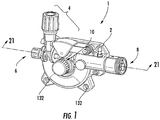
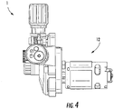
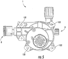
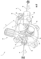
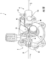
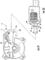
- an exemplary wire feeder 1 includes a housing 2, a tensioning assembly 4, a wire inlet region 6, a wire outlet region 8, and a roller assembly 10.
- a motor 12 is coupled to the roller assembly 10 to drive the roller assembly at a desired rate of speed.
- Wire may be pulled from a spool (not shown) via the wire feeder 1.
- the wire feeder 1 pulls the wire in through the wire inlet region 6, contacts with wire using the roller assembly 10, and pushes the wire out through the wire outlet region 8 to a welding gun (not shown).
- the housing 2 may be a cast arrangement made from any of a variety of appropriate materials, including metals, polymers and the like. In one non-limiting exemplary embodiment, the housing 2 may be made from cast aluminum. The remaining elements of the wire feeder 1 may be mounted to different portions of the housing 2, and thus the housing may be provided with a variety of individual mounting features, as will be described in greater detail in relation to the individual components of the wire feeder 1.
- the wire feeder 1 may draw wire "W" ( FIG. 8 ) in through the wire inlet region 6 from a wire spool by rotational contact with one or more rollers of the roller assembly 10.
- the rollers may push the wire out the wire outlet region 8 for use by the welding torch.
- it is important to ensure that sufficient friction exists between the wire and the rollers to minimize the chance for slippage. It is also important to ensure that not too much friction exists between the wire and the one or more rollers of the roller assembly 10. This balance is complicated further where the wire feeder 1 is configured for use with more than one wire material and/or wire size.
- the tensioning assembly 4 can enable a user to manually adjust the tensioning force on a particular wire being used with the wire feeder 1.
- the tensioning assembly 4 includes a tensioning arm 14 having a first end 16 fitted with a rotatable drive roller 18 and a second end 20 pivotably coupled to the housing 2 via a pivot connection 22.
- the tensioning arm 14 can be rotated between an open configuration and a closed configuration (shown in FIG. 8 ) by rotating the tensioning arm about the pivot connection 22.
- the pivot connection 22 comprises a shoulder screw 24 disposed within respective openings (e.g., opening 26 shown in FIG. 9 ) in the second end 20 of the tensioning arm 14 and the housing 2.
- the drive roller 18 When in the open configuration, the drive roller 18 is separated from an opposing feed roller 30 so that a wire "W” can be fed through the wire feeder 1 in the direction identified by arrow "A.”
- the tensioning arm 14 is biased toward the open configuration by a torsion spring coupled to the pivot connection 22. Once the wire "W” is appropriately positioned within the wire feeder 1, the tensioning arm 14 can then be pivoted about the pivot connection 22 to assume the closed configuration, whereupon the wire "W” is squeezed between the drive roller 18 and the feed roller 30.
- the tensioning assembly 4 may further include a tension knob assembly 32 that is configured to lock the tensioning arm 14 in a desired closed configuration and to apply a desired downward force on the tensioning arm 14.
- the tension knob assembly 32 may include a tension adjustment knob 34, a tension adjustment base 36, a tension adjustment bolt 38 and a tension spring 40.
- the tension adjustment knob 34 may extensibly receive the tension adjustment base 36 therein.
- the tension spring 40 may be positioned between the tension adjustment knob 34 and the tension adjustment base 36 to bias the parts away from each other.
- the tension adjustment base 36, tension spring 40, and tensional adjustment knob 36 may receive a first threaded end 42 of the tension adjustment bolt 38 therein.
- the first threaded end 42 of the tension adjustment bolt 38 may threadably engage the tension adjustment knob 34 so that as the tension adjustment knob 34 is rotated in a first direction as the tension adjustment knob 34 is drawn toward the tension adjustment base 36, thus compressing the tension adjustment spring 40.
- a second end 44 of the tension adjustment bolt 38 may be pivotably coupled to the housing 2 via a tensioning pivot connection 46 positioned adjacent the wire inlet region 6 of the wire feeder 1.
- the tensioning pivot connection 46 comprises a spring roll pin 48 disposed within respective openings 50, 52 in the second end 44 of the tensioning knob assembly 32 and the housing 2, respectively.
- the tensioning knob assembly 32 can be rotated between an open configuration and a closed configuration (shown in FIG. 8 ) by rotating the tensioning arm 14 about the tensioning pivot connection 46.
- the tensioning knob assembly 32 When in the open configuration, the tensioning knob assembly 32 is separated from the tensioning arm 14 so that the tensioning arm 14 can be rotated into the closed configuration.
- the tensioning knob assembly 32 can then be pivoted about the tensioning pivot connection 46 to assume the closed configuration, whereupon a body portion 54 of the tension adjustment bolt 38 is received within a yoke portion 56 of the tensioning arm 14.
- the tension adjustment base 36 engages a top surface 58 of the tensioning arm 14 so that the biasing force of the tension spring 40 is applied to the top surface 58.
- This biasing force is, in turn, directly applied to the drive roller 18 to maintain a desired downward force on the wire "W" disposed between the drive roller 18 and the feed roller 30.
- Adjustment of the downward force can be made by rotating the tension adjustment knob 34.
- the tension adjustment knob 34 By rotating the tension adjustment knob 34 in a first direction, the threaded engagement between the tension adjustment knob 34 and the tension adjustment bolt 38 causes the tension adjustment knob 34 to move away from the tension adjustment base 36, thus reducing compression of the tension spring 40 and reducing downward force on the tension arm 14.
- Rotating the tension adjustment knob 34 in a second direction opposite the first direction causes the tension adjustment knob 34 to move closer to the tension adjustment base 36, thus increasing compression of the tension spring 40 and increasing downward force on the tension arm 14.
- the spring roll pin 48 disposed within respective openings 50, 52 in the second end 44 of the tension adjustment bolt 38 and the housing 2 has a lengthwise axis that is parallel to the axis of the wire "W" travelling through the wire feeder 1.
- This orientation is advantageous because it enables the tension knob assembly 32 to be rotated away from a surface to which the wire feeder 1 is attached.
- the wire feeder 1 may be attached to a center divider (not shown) of a portable welding device.
- Prior wire feeder designs have included tension knobs that rotate about an axis that is perpendicular to the axis of the wire being fed through the wire feeder. Such an arrangement can be disadvantageous because in rotating, such tension knobs can interfere with other equipment located within the portable welding device. With the disclosed configuration, the tension knob assembly 32 rotates outward, away from the center divider, and thus it is both easier to manipulate and less likely to interfere with other elements of the portable welding device.
- the drive assembly may include a reversible feed roller 30 that can be configured to selectively accept at least two different wire sizes.
- the feed roller 30 may have first and second circumferential grooves 60, 62, each having a desired depth and width to accept a welding wire having a particular diameter.
- the desired groove 60, 62 can be selected by simply flipping the orientation of the feed roller 30 on the associated drive shaft (not shown).
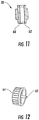
- a knob 64 FIG. 12 ) having a threaded body portion 65 can threadably connect to an inner threaded portion of the drive shaft to lock the feed roller 30 to the drive shaft in the selected orientation.
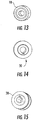
- An exemplary wire drive roller 18 is shown in FIG. 13 and, as shown, it may be provided without grooves.
- An exemplary feed roller 30 is shown in FIGS. 14 and 15 , in which a first side of the feed roller 30 corresponds to a groove of about 0.024 inches (0.6 mm), while a second side of the feed roller 30 corresponds to a groove of about 0.030 inches (0.8 mm).
- the feed roller 30 would be oriented so that the associated label is pointing outward.
- the knob 64 may then be used to lock the feed roller in place.
- the feed roller 30 would be oriented so that the associated label is pointing outward.
- the knob 64 may then be used to lock the feed roller in place.
- the aforementioned sizes and number of grooves are merely exemplary, and others sizes and number of grooves may be used.
- an exemplary gearing arrangement 66 is shown for the wire feeder 1.
- the gearing arrangement 66 is partially housed in a gear housing 67 and partially housed in a portion of the housing 2.
- the gear housing 67 encases a plurality of intermeshing gears 68, 70, 72, 74, 76, 78, which may include one or more driven gears, one or more compound gears, arranged to provide a desired output rotational speed to the feed roller 30 based on a particular speed of the motor 12.
- the feed roller 30 is engaged with, and keyed to, a drive shaft 80 which is coupled to the gearing arrangement 66.
- the gear housing 67 and wire feeder housing 2 may be sized so that a variety of gear types, sizes, and combinations can be employed to achieve a desired wire feed speed given a known motor rotational speed. This is an advantage over prior designs which are sized to accept a single gearing arrangement.
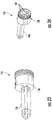
- FIGS. 18-20 show an exemplary wire guiding arrangement for the wire feeder 1.
- An inlet wire guide 82 may be disposed within a cylindrical opening 84 formed in the housing 2 adjacent to the wire inlet region 6.
- a torch side wire guide 86 may be disposed within a cylindrical opening 88 formed in the housing 2 adjacent to the wire outlet region 8.
- the inlet and torch side wire guides 82, 86 have respective axial openings 90, 92 oriented coaxially with the wire "W" when the guides are disposed in the openings 84, 88 of the housing 2.
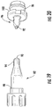
- each guide 82, 86 may respectively include a tapered nose portion 94, 96.
- the tapered nose portion 94 of the inlet wire guide 82 is shown best in FIG. 19
- the tapered nose portion 96 of the torch side wire guide 86 is shown in FIG. 20 .
- the tapered nose portion 94 of the inlet wire guide is generally round, while the tapered nose portion 96 of the torch side wire guide 86 is chisel shaped to enable the tapered nose portion 96 to be positioned as close to the feed and drive rollers 18, 30 as possible.
- the inlet wire guide 82 and the torch side wire guide 86 may have respective enlarged shoulder regions 98, 100, that are configured to abut respective surfaces of the housing 2 adjacent the respective cylindrical openings 84, 88 formed in the housing 2. As will be appreciated, these shoulder regions 98, 100 prevent the respective wire guides 82, 86 from moving in the direction of the wire "W" (indicated by arrow "A" in FIG. 18 ) during operation.
- the inlet wire guide 82 and torch side wire guide 86 may be formed of a suitable polymer material.
- the wire feeder 1 may include features that enable simple plug compatibility with a torch connector 102.
- the housing 2 of the wire feeder 2 may have a cylindrical opening configured to receive a torch connector 102 therein.
- the housing 2 includes a cylindrical opening 101 formed therein having a first end 103 adjacent to the wire outlet region 8 of the wire feeder 1.
- the cylindrical opening 101 may be sized to accept a projecting cylindrical portion 104 of the torch connector 102 therein. In use, the projecting cylindrical portion 104 may be pressed into the cylindrical opening 101 until a side surface 105 of the torch connector 102 engages a side surface of the housing 106.
- the distal end 108 of the projecting cylindrical portion 104 may be positioned so that a recess 109 in the distal end 108 aligns generally with the projecting end (not shown) of a thumb screw 110 ( FIG. 18 ).
- Turning the thumb screw 110 may engage the projecting end of the thumb screw 110 with the recess 109, locking the torch connector 102 in place.
- a gas inlet portion 112 of the torch connector 102 may be positioned directly adjacent to a gas inlet 114 formed in the housing 2.
- the gas inlet portion 112 of the torch connector 102 may include a plurality of radially disposed openings 116, with a pair of o-rings 118, 120 disposed on either side thereof.
- a gas supply nipple 122 ( FIG. 18 ) may be disposed in the gas inlet 114.
- the gas supply nipple 122 may be connected to a suitable source of shielding gas.
- shielding gas can be provided by the wire feeder 1 to the torch via the torch connector 102 without the need for an adapter.
- an adapter such as a "Euro Adapter,” to enable users having “Euro” connectors to couple such torches to the disclosed wire feeder 1.
- an adapter 124 may have a first portion 126 receivable within the cylindrical opening 101 of the housing 2, and a second portion 128 having connection ports 130 suitable for receiving a Euro connection. It will be appreciated that an adapter having a Euro connection is merely exemplary, and that an appropriate adapter can include other connection types, as desired.
- the disclosed wire feeder 1 may have a plurality of features configured to enable the wire feeder to be fixed to a surface of an associated portable welding device.
- the housing 2 includes a plurality of fastener openings 132 sized to receive suitable fasteners, such as screws, bolts or the like, to fix the wire feeder in place within the welding device.
Landscapes
- Engineering & Computer Science (AREA)
- Physics & Mathematics (AREA)
- Plasma & Fusion (AREA)
- Mechanical Engineering (AREA)
- Wire Processing (AREA)
- Forwarding And Storing Of Filamentary Material (AREA)
Applications Claiming Priority (3)
| Application Number | Priority Date | Filing Date | Title |
|---|---|---|---|
| US201462079750P | 2014-11-07 | 2014-11-07 | |
| US201462076750P | 2014-11-07 | 2014-11-07 | |
| EP15190229.3A EP3017900A3 (de) | 2014-11-07 | 2015-10-16 | Multifunktionsdrahtzufuhr für ein tragbares schweisssystem |
Related Parent Applications (1)
| Application Number | Title | Priority Date | Filing Date |
|---|---|---|---|
| EP15190229.3A Division EP3017900A3 (de) | 2014-11-07 | 2015-10-16 | Multifunktionsdrahtzufuhr für ein tragbares schweisssystem |
Publications (1)
| Publication Number | Publication Date |
|---|---|
| EP3375559A1 true EP3375559A1 (de) | 2018-09-19 |
Family
ID=54359848
Family Applications (2)
| Application Number | Title | Priority Date | Filing Date |
|---|---|---|---|
| EP18168185.9A Withdrawn EP3375559A1 (de) | 2014-11-07 | 2015-10-16 | Multifunktionsdrahtzufuhr für ein tragbares schweisssystem |
| EP15190229.3A Withdrawn EP3017900A3 (de) | 2014-11-07 | 2015-10-16 | Multifunktionsdrahtzufuhr für ein tragbares schweisssystem |
Family Applications After (1)
| Application Number | Title | Priority Date | Filing Date |
|---|---|---|---|
| EP15190229.3A Withdrawn EP3017900A3 (de) | 2014-11-07 | 2015-10-16 | Multifunktionsdrahtzufuhr für ein tragbares schweisssystem |
Country Status (4)
| Country | Link |
|---|---|
| US (2) | US10486258B2 (de) |
| EP (2) | EP3375559A1 (de) |
| CN (1) | CN105583496A (de) |
| BR (1) | BR102015027877B1 (de) |
Families Citing this family (7)
| Publication number | Priority date | Publication date | Assignee | Title |
|---|---|---|---|---|
| AU2016430805A1 (en) * | 2016-11-23 | 2019-05-23 | The Esab Group, Inc. | Wire feeder with automatically adjustable wire clamping force |
| HU231066B1 (hu) * | 2017-03-23 | 2020-04-28 | Cooptim Ipari Kft | Huzaltoló egység |
| DE102017113887B4 (de) * | 2017-06-22 | 2019-01-31 | Carl Cloos Schweißtechnik Gesellschaft mit beschränkter Haftung | Drahtfördervorrichtung und Spanneinrichtung |
| CN107598338A (zh) * | 2017-09-21 | 2018-01-19 | 浙江雅创机电科技有限公司 | 一种mig电焊机 |
| EP4772306A2 (de) * | 2018-11-02 | 2026-07-08 | Esab Ab | Bedienfeld für eine schweissvorrichtung |
| CN111099428B (zh) * | 2019-11-22 | 2021-06-01 | 中国科学院自动化研究所 | 一种送丝装置的执行端及送丝装置 |
| US11738403B2 (en) * | 2020-01-27 | 2023-08-29 | The Esab Group Inc. | Push pull torch |
Citations (4)
| Publication number | Priority date | Publication date | Assignee | Title |
|---|---|---|---|---|
| JPS59147778A (ja) * | 1983-02-15 | 1984-08-24 | Hitachi Ltd | 溶接用ワイヤ送給装置 |
| WO2003022501A2 (en) * | 2001-09-11 | 2003-03-20 | Lajos Kerekes | Wire feeding apparatus |
| WO2008018961A1 (en) * | 2006-08-10 | 2008-02-14 | Illinois Tool Works Inc. | Welding wire feed system and method |
| US20140151350A1 (en) * | 2012-11-30 | 2014-06-05 | Illinois Tool Works Inc. | System and method for determining welding wire diameter |
Family Cites Families (20)
| Publication number | Priority date | Publication date | Assignee | Title |
|---|---|---|---|---|
| US343083A (en) | 1886-06-01 | John joseph charles smith | ||
| US5225657A (en) * | 1992-01-17 | 1993-07-06 | The Lincoln Electric Company | Plasma-arc torch system with filter |
| US5816466A (en) | 1996-04-19 | 1998-10-06 | The Lincoln Electric Company | Wire feeding apparatus |
| HU222201B1 (hu) | 1997-09-09 | 2003-05-28 | Lajos Kerekes | Huzaltoló egység |
| US6286748B1 (en) | 1999-12-27 | 2001-09-11 | Elco Enterprises, Inc. | Welding wire feeder |
| US6388234B1 (en) | 2000-05-25 | 2002-05-14 | Illinois Tool Works Inc. | Apparatus and methods for directing and feeding wire |
| US6427894B1 (en) | 2000-10-19 | 2002-08-06 | The Esab Group, Inc. | Electrode wire feeder for an arc welding system |
| US6568578B1 (en) * | 2001-03-02 | 2003-05-27 | Mk Products | Welding wire feed mechanism |
| US7026574B2 (en) | 2003-07-22 | 2006-04-11 | Lincoln Global, Inc. | Wire gripper for a drive unit of a wire feeder |
| US7383973B2 (en) | 2004-03-15 | 2008-06-10 | Lincoln Global, Inc. | Drive rollers for wire feeding mechanism |
| US7531768B2 (en) | 2004-04-08 | 2009-05-12 | Illinois Tool Works Inc. | Wire feeder pinch force mechanism |
| US7977604B2 (en) * | 2006-08-10 | 2011-07-12 | Illinois Tool Works Inc. | Wire drive roll |
| US20080156925A1 (en) | 2007-01-03 | 2008-07-03 | Elco Enterprises, Inc. | Wire Dispensing System |
| FR2929145B1 (fr) | 2008-03-27 | 2010-03-12 | Numalliance | Poste d'amenage |
| US8450647B2 (en) | 2008-05-12 | 2013-05-28 | Illinois Tool Works Inc. | Drive roll for a wire feeder |
| US8569653B2 (en) | 2009-11-02 | 2013-10-29 | Lincoln Global, Inc. | Drive roll assembly for wire feeder |
| US10315269B2 (en) | 2010-12-16 | 2019-06-11 | Illinois Tool Works Inc. | Welding wire feeder with tongue and groove feature |
| US9586283B2 (en) * | 2011-03-29 | 2017-03-07 | Illinois Tool Works Inc. | Wire feeder tensioner with definitive settings |
| KR20140002117U (ko) | 2012-10-04 | 2014-04-15 | 신한통상 주식회사 | 용접 와이어 송급 장치 |
| CN103433596A (zh) | 2013-07-25 | 2013-12-11 | 湖州天和机械有限公司 | 一种电焊机的自动送丝机构 |
-
2015
- 2015-10-16 EP EP18168185.9A patent/EP3375559A1/de not_active Withdrawn
- 2015-10-16 EP EP15190229.3A patent/EP3017900A3/de not_active Withdrawn
- 2015-11-05 US US14/933,224 patent/US10486258B2/en active Active
- 2015-11-05 BR BR102015027877-2A patent/BR102015027877B1/pt not_active IP Right Cessation
- 2015-11-06 CN CN201510751049.5A patent/CN105583496A/zh active Pending
-
2019
- 2019-07-24 US US16/520,721 patent/US20190344373A1/en not_active Abandoned
Patent Citations (4)
| Publication number | Priority date | Publication date | Assignee | Title |
|---|---|---|---|---|
| JPS59147778A (ja) * | 1983-02-15 | 1984-08-24 | Hitachi Ltd | 溶接用ワイヤ送給装置 |
| WO2003022501A2 (en) * | 2001-09-11 | 2003-03-20 | Lajos Kerekes | Wire feeding apparatus |
| WO2008018961A1 (en) * | 2006-08-10 | 2008-02-14 | Illinois Tool Works Inc. | Welding wire feed system and method |
| US20140151350A1 (en) * | 2012-11-30 | 2014-06-05 | Illinois Tool Works Inc. | System and method for determining welding wire diameter |
Also Published As
| Publication number | Publication date |
|---|---|
| CN105583496A (zh) | 2016-05-18 |
| US10486258B2 (en) | 2019-11-26 |
| US20190344373A1 (en) | 2019-11-14 |
| EP3017900A3 (de) | 2016-10-12 |
| BR102015027877A2 (pt) | 2016-05-24 |
| US20160129522A1 (en) | 2016-05-12 |
| BR102015027877B1 (pt) | 2021-06-01 |
| EP3017900A2 (de) | 2016-05-11 |
Similar Documents
| Publication | Publication Date | Title |
|---|---|---|
| US20190344373A1 (en) | Multifunction wire feeder for a portable welding system | |
| US6066833A (en) | Apparatus and method for selectively changing welding wire | |
| CN101574753B (zh) | 自定心装置 | |
| US6427894B1 (en) | Electrode wire feeder for an arc welding system | |
| US20200353554A1 (en) | System and method for adjusting feed roll position in a welding torch | |
| EP2651588B1 (de) | Schweissdrahtvorschubvorrichtung mit drahtführung und einem drucktaster zum halten der drahtführung | |
| CA3043304C (en) | Wire feeder with automatically adjustable wire clamping force | |
| WO2008018960A1 (en) | Wire drive roll with a plurality of grooves for advancingwires and having mounting features uniquely associated with only one of the grooves; a drive mechanism with such wire drive roll; welding system with such drive mechanism | |
| CN111251602B (zh) | 送丝机构及3d打印机 | |
| US3009619A (en) | Wire feed mechanism | |
| US20190143439A1 (en) | System and method for guiding welding wire through a torch | |
| CN212242147U (zh) | 送丝机构及3d打印机 | |
| DE202017102022U1 (de) | Drahtvorschubeinrichtung für Schweißdrähte | |
| US3708647A (en) | Welding head drive unit | |
| US10239148B2 (en) | Motor assembly for a push-pull welding torch | |
| US4172545A (en) | Planetary wire feeder | |
| US11738403B2 (en) | Push pull torch | |
| US2122194A (en) | Automatic welding torch | |
| JP6607767B2 (ja) | 溶接ワイヤ送給装置およびトーチコネクション | |
| KR20190081781A (ko) | 로터리 노즐 및 이를 구비한 자동절단 압착기 | |
| US3688071A (en) | Welding head with detachable power handle | |
| AT503608B1 (de) | Rolle für eine einrichtung zur förderung eines schweissdrahtes | |
| CN108923220A (zh) | 一种改进型线束端子自动压接设备的引线装置 | |
| TW201733722A (zh) | 具可調式噴嘴之送線裝置 | |
| JP2016190246A (ja) | 溶接ワイヤ送給装置 |
Legal Events
| Date | Code | Title | Description |
|---|---|---|---|
| PUAI | Public reference made under article 153(3) epc to a published international application that has entered the european phase |
Free format text: ORIGINAL CODE: 0009012 |
|
| STAA | Information on the status of an ep patent application or granted ep patent |
Free format text: STATUS: THE APPLICATION HAS BEEN PUBLISHED |
|
| AC | Divisional application: reference to earlier application |
Ref document number: 3017900 Country of ref document: EP Kind code of ref document: P |
|
| AK | Designated contracting states |
Kind code of ref document: A1 Designated state(s): AL AT BE BG CH CY CZ DE DK EE ES FI FR GB GR HR HU IE IS IT LI LT LU LV MC MK MT NL NO PL PT RO RS SE SI SK SM TR |
|
| RIN1 | Information on inventor provided before grant (corrected) |
Inventor name: FLICKINGER, SEAN WILLIAM Inventor name: EVANS, DARYLL SCOTT |
|
| STAA | Information on the status of an ep patent application or granted ep patent |
Free format text: STATUS: REQUEST FOR EXAMINATION WAS MADE |
|
| 17P | Request for examination filed |
Effective date: 20190212 |
|
| RBV | Designated contracting states (corrected) |
Designated state(s): AL AT BE BG CH CY CZ DE DK EE ES FI FR GB GR HR HU IE IS IT LI LT LU LV MC MK MT NL NO PL PT RO RS SE SI SK SM TR |
|
| STAA | Information on the status of an ep patent application or granted ep patent |
Free format text: STATUS: EXAMINATION IS IN PROGRESS |
|
| 17Q | First examination report despatched |
Effective date: 20200923 |
|
| RAP3 | Party data changed (applicant data changed or rights of an application transferred) |
Owner name: THE ESAB GROUP INC. |
|
| STAA | Information on the status of an ep patent application or granted ep patent |
Free format text: STATUS: THE APPLICATION IS DEEMED TO BE WITHDRAWN |
|
| 18D | Application deemed to be withdrawn |
Effective date: 20220611 |