EP3375597A2 - Bande d'étanchéité et procédé de fabrication d'une bande d'étanchéité - Google Patents
Bande d'étanchéité et procédé de fabrication d'une bande d'étanchéité Download PDFInfo
- Publication number
- EP3375597A2 EP3375597A2 EP18160648.4A EP18160648A EP3375597A2 EP 3375597 A2 EP3375597 A2 EP 3375597A2 EP 18160648 A EP18160648 A EP 18160648A EP 3375597 A2 EP3375597 A2 EP 3375597A2
- Authority
- EP
- European Patent Office
- Prior art keywords
- cuts
- foam carrier
- strip
- incisions
- thickness direction
- Prior art date
- Legal status (The legal status is an assumption and is not a legal conclusion. Google has not performed a legal analysis and makes no representation as to the accuracy of the status listed.)
- Granted
Links
Images


Classifications
-
- C—CHEMISTRY; METALLURGY
- C09—DYES; PAINTS; POLISHES; NATURAL RESINS; ADHESIVES; COMPOSITIONS NOT OTHERWISE PROVIDED FOR; APPLICATIONS OF MATERIALS NOT OTHERWISE PROVIDED FOR
- C09J—ADHESIVES; NON-MECHANICAL ASPECTS OF ADHESIVE PROCESSES IN GENERAL; ADHESIVE PROCESSES NOT PROVIDED FOR ELSEWHERE; USE OF MATERIALS AS ADHESIVES
- C09J7/00—Adhesives in the form of films or foils
- C09J7/20—Adhesives in the form of films or foils characterised by their carriers
- C09J7/22—Plastics; Metallised plastics
- C09J7/26—Porous or cellular plastics
-
- B—PERFORMING OPERATIONS; TRANSPORTING
- B26—HAND CUTTING TOOLS; CUTTING; SEVERING
- B26D—CUTTING; DETAILS COMMON TO MACHINES FOR PERFORATING, PUNCHING, CUTTING-OUT, STAMPING-OUT OR SEVERING
- B26D3/00—Cutting work characterised by the nature of the cut made; Apparatus therefor
- B26D3/08—Making a superficial cut in the surface of the work without removal of material, e.g. scoring, incising
- B26D3/085—On sheet material
-
- E—FIXED CONSTRUCTIONS
- E04—BUILDING
- E04B—GENERAL BUILDING CONSTRUCTIONS; WALLS, e.g. PARTITIONS; ROOFS; FLOORS; CEILINGS; INSULATION OR OTHER PROTECTION OF BUILDINGS
- E04B1/00—Constructions in general; Structures which are not restricted either to walls, e.g. partitions, or floors or ceilings or roofs
- E04B1/62—Insulation or other protection; Elements or use of specified material therefor
- E04B1/66—Sealings
- E04B1/68—Sealings of joints, e.g. expansion joints
- E04B1/6812—Compressable seals of solid form
-
- C—CHEMISTRY; METALLURGY
- C09—DYES; PAINTS; POLISHES; NATURAL RESINS; ADHESIVES; COMPOSITIONS NOT OTHERWISE PROVIDED FOR; APPLICATIONS OF MATERIALS NOT OTHERWISE PROVIDED FOR
- C09J—ADHESIVES; NON-MECHANICAL ASPECTS OF ADHESIVE PROCESSES IN GENERAL; ADHESIVE PROCESSES NOT PROVIDED FOR ELSEWHERE; USE OF MATERIALS AS ADHESIVES
- C09J2301/00—Additional features of adhesives in the form of films or foils
- C09J2301/10—Additional features of adhesives in the form of films or foils characterized by the structural features of the adhesive tape or sheet
- C09J2301/18—Additional features of adhesives in the form of films or foils characterized by the structural features of the adhesive tape or sheet characterized by perforations in the adhesive tape
-
- C—CHEMISTRY; METALLURGY
- C09—DYES; PAINTS; POLISHES; NATURAL RESINS; ADHESIVES; COMPOSITIONS NOT OTHERWISE PROVIDED FOR; APPLICATIONS OF MATERIALS NOT OTHERWISE PROVIDED FOR
- C09J—ADHESIVES; NON-MECHANICAL ASPECTS OF ADHESIVE PROCESSES IN GENERAL; ADHESIVE PROCESSES NOT PROVIDED FOR ELSEWHERE; USE OF MATERIALS AS ADHESIVES
- C09J2301/00—Additional features of adhesives in the form of films or foils
- C09J2301/30—Additional features of adhesives in the form of films or foils characterized by the chemical, physicochemical or physical properties of the adhesive or the carrier
- C09J2301/302—Additional features of adhesives in the form of films or foils characterized by the chemical, physicochemical or physical properties of the adhesive or the carrier the adhesive being pressure-sensitive, i.e. tacky at temperatures inferior to 30°C
Definitions
- the present invention relates to a sealing strip and in particular a sealing strip roll and also to a method for producing this sealing strip roll.
- Such sealing tapes which can be unwound from sealing tape rolls, are usually used for sealing joints, for example between a frame profile of a window or a door on the one hand and a building wall on the other hand.
- additional films increase the vapor impermeability on a side surface of the sealing strip.
- externally disposed films have the disadvantage that they can be damaged during installation. Therefore, sealing tapes are known from the prior art, which have such film strips in the interior of a -Shaumstoffes. However, these are more complicated to manufacture. From the EP 2 990 553 A1 For example, a method is known in which such a film strip is introduced into a foam. However, this process is relatively complicated and also requires rotation of individual foam strips during manufacture.
- the present invention is therefore based on the object to propose a method for producing such a sealing tape, which is easier to perform compared to the prior art.
- This object is achieved by a method according to the independent claim as a sealing tape.
- Advantageous embodiments and further developments are the subject of the dependent claims.
- a foam carrier is provided in a first step, and this foam carrier, which may also be doubled, is transported in a predetermined transport direction.
- the foam carrier on a first surface and a second surface, said first surface and the second surface facing each other.
- first cuts are made in the first surface, wherein these first cuts extend at least also in a thickness direction of the foam carrier.
- second cuts are introduced into the second surface, wherein these second cuts extend at least also in a thickness direction of the foam carrier.
- the opposing surfaces are thus surfaces that are parallel to each other and between which the actual foam is arranged.
- the thickness direction is in particular a direction which is perpendicular to the surfaces mentioned.
- the cuts are not continuously introduced into the band, that is, the band is not completely separated with the said cuts, but it is particularly preferred in the cuts only incisions. According to the invention, however, such cuts are made both in the first surface and in the second surface. In the following, the terms cut and incision are used interchangeably.
- the first and second cuts are thus preferably cuts or incisions which are introduced into the foam in the above-mentioned method step. These are preferably initial first and second cuts. As explained in more detail below, further (preferred) method still further first and second cuts are introduced into the foam carrier. Also in the case of these further cuts, a distinction is made in the context of the description between further first cuts which are introduced into the first surface and further second cuts which are introduced into the second surface. Preferably, therefore, the further cuts are introduced into the foam carrier in time after the above-mentioned (initial) cuts.
- a film strip, an adhesive tape strip and / or an adhesive-type medium is introduced into at least one of the first sections and into at least one of the second sections.
- These elements later represent the barrier layer in the foam carrier.
- a film strip or an adhesive tape strip can be unwound or pulled off, for example, from a film web or an adhesive tape web. It would be possible for this film web or the adhesive tape web to be pressed against the respective foam. If an adhesive-like liquid medium is used, this can be introduced into the cut, for example using nozzles, such as flat nozzles, melt nozzles, mixing nozzles, and / or via a corresponding roll application, for which purpose, for example, transfer rolls can be used. However, preference is given to an introduction by means of nozzles.
- first and second cuts are preferably introduced in the further course of the method.
- a plurality of incisions are made, which are preferably offset from each other in a width direction.
- these multiple cuts are equidistant from each other.
- these incisions are each parallel to each other.
- the incisions in the first surface are offset from the incisions in the second surface in the width direction B.
- an adhesive tape web can be provided by means of a release film, which is detached, for example, from the adhesive tape web. Subsequently, this adhesive tape web can be introduced into said section.
- this adhesive tape web deflecting elements can be used, for example, which project sword-like in the generated section.
- such an adhesive tape web could itself comprise a layer of an adhesive tape or a layer of a hotmelt adhesive. It would also be possible to apply such a film web with a spray adhesive. In a further alternative approach, it would also be possible to introduce the adhesive web or the like, or even a liquid adhesive medium from below and from above into the foam carrier.
- the cuts in the foam carrier can for example be introduced using a plurality of knives, which are brought from above or from below to the foam carrier.
- the foam sheet preferably moves in the transport direction.
- Preference for cutting fixed mounted blades are provided. These fixed mounted knives, e.g. Circular knives or oscillating knives cut into the foam web.
- Rotary blades can preferably rotate in opposite directions or in the same direction.
- cuts are understood to mean that these cuts have at least one component that also extends in the thickness direction, but preferably also a component that extends in a width direction of the foam carrier.
- the cuts preferably also extend in the longitudinal direction of the foam carrier or in its transport direction. In a further advantageous method, cuts are produced which extend essentially only in the thickness direction.
- the cuts are introduced at an angle different from 0 ° with respect to the thickness direction.
- this angle is greater than 5 °, preferably greater than 10 ° and preferably greater than 15 °.
- this angle is less than 60 °, preferably less than 50 ° and particularly preferably less than 45 °.
- the first cuts and the second cuts are differently inclined with respect to the thickness direction.
- the two sections in the top and bottom are exactly mirror-symmetrical with respect to the thickness direction inclined.
- the angle which the cuts enclose is greater than the respective angle with respect to the thickness direction.
- the foam carrier is at least partially in the width direction (ie in particular in one of the direction of transport perpendicular direction) stretched.
- Such an elongation can take place, for example, by successive guide rollers.
- the cuts are also widened so that a film element or the adhesive can be more easily introduced into the cuts.
- a strip-shaped element is introduced into at least one section, wherein at least one end section of this strip-shaped element also bears against a surface. If, for example, such a film element is introduced into an incision on the first surface, an end section can also be applied or glued to said first surface.
- the strip element is angled in at least one region, in particular in that region in which it emerges from said incision.
- this strip-shaped element is adhesively attached or glued to said surface of the foam carrier and / or on both cutting edges.
- the tension of the foam carrier is restored or loosened so that the cuts around the inserted foil elements can close.
- the "initial" sections are preferably closed or glued after the introduction of the films, preferably in order to obtain a coherent foam body again.
- the further cuts are introduced into the foam carrier.
- the further cuts are introduced in such a way that they intersect with the respective first introduced cuts. This means that, for example, another cut, which has been introduced into a lower surface of the foam carrier, a first cut, which has been previously introduced into an upper surface of the foam carrier cuts. Due to the different extension directions, these cuts intersect at a predetermined angle different from 0 °.
- the first cuts and / or the second cuts extend more than 50% of the thickness of the foam carrier.
- these first and second cuts extend for more than two thirds of the width of the foam carrier.
- the respective incisions protrude so far into the foam carrier, that they cover each other at least in the thickness direction of the foam carrier (as viewed in a projection along the transport direction of the foam carrier). In this way, as explained in more detail later, a continuous barrier layer can be formed.
- first and second cuts are introduced into the first and second surfaces in a further method step.
- the initial first cuts made in the first surface and the initial second cuts made in the second surface are offset with respect to each other in the width direction of the foam carrier. This offset ensures that at no point is the foam carrier completely severed.
- the initial first cuts made in the first surface and the other first cuts made in the first surface are offset in the width direction of the foam carrier with respect to each other.
- the initial second cuts introduced into the second surface and the further second cuts introduced into the second surface are offset with respect to each other in the width direction of the foam carrier.
- At least one further cut cuts through a section of a first cut, and in particular also an inserted foil element. This means that during the process at least a portion of the film introduced into the cut is severed.
- the foam carrier is preferably tensioned again, so that the further cuts also widen.
- Foil elements in turn are preferred in these sections in the thickness direction or introduced an adhesive. This results in a total of a foam carrier with introduced films, that is, more precisely, two film elements are introduced, but overlap in a certain area, so that a total of the full thickness direction, a film element (or two intersecting film elements) extends.
- the foam web is compressed and particularly preferably compressed on a self-adhesive and in particular a self-adhesive layer (and / or a self-adhesive tape, such as a double-sided adhesive tape).
- this compressed web is rolled up onto a roll and in particular onto a large roll, so that a total of one sealing strip roll with inserted film strips is produced.
- the self-adhesive layer or self-adhesive film is preferably located on one of the two surfaces.
- an adhesive layer and in particular a self-adhesive film is applied to the foam web and, more particularly, to an outer surface of the foam web.
- this adhesive layer and / or self-adhesive film is attached to at least one of the two surfaces, in which the incisions were introduced.
- this adhesive layer and / or self-adhesive film at least partially covers said incisions.
- the large roll is severed.
- strips are advantageously severed, more preferably, each of these strips having a film element introduced from the top and a film element introduced from the underside, which intersect at a predetermined intersection point.
- the present invention is further directed to a sealing tape.
- This sealing strip has a foam carrier, wherein this foam carrier extends in a predetermined longitudinal direction and has a first surface and a second surface, wherein these surfaces face each other.
- At least one first cut is preferably arranged in the first surface, which extends at least also in a thickness direction, this thickness direction extending from the first surface to the second surface and at least one cut in the second surface extends in this thickness direction, wherein at least one of the cuts in a extending from 0 ° different angle to the thickness direction and in the two sections each a film strip, an adhesive tape strip and / or an adhesive-like medium is introduced.
- the sealing tape has both an incision in the first surface and an incision in the second surface, wherein in these sections, the film element or the adhesive or the adhesive tape is introduced.
- the first and second intersections intersect. In this way, a continuous film strip or a continuous barrier is achieved in total in the thickness direction.
- At least a portion of a film strip is also applied to a surface in which the cut has been made.
- end portions of both film elements are in each case on those surfaces on which they were introduced or in which said incisions were introduced.
- the foam is an impregnated foam.
- the foam is a resilient foam.
- the sealing tape is compressed and more preferably prefabricated as a roll. The sealing tape is preferably impregnated for delayed recovery.
- the further section has a V-shaped profile.
- the (initial) cuts and the further cuts have a different extent in the thickness direction of the foam carrier.
- the initial cut in this thickness direction may preferably extend at least 1.5 times as far, preferably at least twice as far as the further cut.
- This V-shaped cut preferably protrudes less deeply into the foam body than the above-mentioned first cuts.
- this V-shaped cut protrudes by less than 60%, preferably by less than 50%, preferably by less than 40% and particularly preferably by less than 30% of the thickness of the foam carrier into it
- a further cut is provided in at least one surface and in this further section is a film strip or tape strips double-layered one. More precisely, this film strip or adhesive tape strip preferably lies on or on the two flanks of the incision.
- V-shaped cuts are made in the foam carrier in at least one method step.
- the initial first and second cuts are introduced into the foam carrier.
- the aforementioned V-shaped sections are preferably introduced into the foam carrier.
- the V-shaped cuts on the respective opposite surface of the foam carrier ie that surface, which is opposite to the surface with the associated initial cut) are introduced.
- the V-shaped cuts are made in such a depth that they almost or completely reach the foil strips introduced into the first cuts. Also in this way results in a closed film layer.
- Foil strips, strips of adhesive tape or an adhesive-like medium are also preferably introduced into the V-shaped cuts.
- a V-shaped film strip can be introduced.
- these foil strips introduced into the V-shaped cuts also protrude out of the V-shaped cut and are preferably located on the respective surface.
- the further first and second cuts are preferably not offset with respect to the first and second cuts.
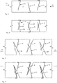
- FIG. 1 shows a representation of a foam carrier 2.
- This foam carrier 2 is transported at the beginning of the process in a transport direction T, wherein this transport direction is perpendicular to the plane of the figure here.
- This transport direction T is thus also the longitudinal direction of the foam carrier.
- the reference character D denotes a thickness direction which is perpendicular to the transport direction or the longitudinal direction.
- the reference character B indicates a width direction of the vehicle carrier.
- the reference numeral 2a denotes a first surface of the foam carrier 2 and the reference character 2b a second surface. These two surfaces are opposite each other or have between them the actual foam.
- the thickness direction D also extends between these two surfaces. In each case a plurality of incisions 12, 14 are preferably introduced into both surfaces 2 a and 2 b.
- recesses 12 and 14 were introduced into the foam carrier 2, that is, into both the first surface 2a and the second surface 2b.
- the incisions 12 were introduced into the first surface 2a and the second incisions 14 into the second surface 2b. It can be seen that these cuts do not extend along the entire thickness direction but, for example, more than 50%, preferably more than 60% and particularly preferably more than 70% of the thickness direction. The depth of these cuts is advantageous in order to ensure sufficient expansion of the cuts in a further process step by tension of the wearer.
- the foam carrier is stretched again, so that the further cuts 22 and 24 expand.
- film elements are now in turn introduced into these further sections. These film elements again have a portion which projects into the respective cuts and another portion which bears against the respective surface.
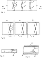
- Strip shown S1, S2 and S3 are separated or roles of the large role shown process step.
- Each of these strips contains two foil elements 6, which intersect at the point of intersection K.
- the foam is compressed to a self-adhesive (not shown).
- a self-adhesive strip is shown, which adheres to the surface 2b of the foam carrier and preferably adheres flat. This self-adhesive strip thus also covers the end section 6a, which protrudes from the cut 14.
- the foam of the fully compressed state (see. Fig. 11 ) again partially back, but the film elements remain in its interior gapless (see. Fig. 12 ).
- the foam can be fastened to the wall element 32.
- the reference numeral 34 refers to a second wall element.
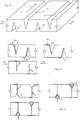
- FIG. 13 shows a perspective view of a foam carrier with introduced and expanded sections 12 and 14.
- a film element 6 is again introduced into a first cut, the end section 6a of the film element abutting the surface 2a (cf. Fig. 14 ).
- the foam carrier is relaxed again, so that overall the film element is present in its interior, wherein here the film element extends in the thickness direction (lower picture in FIG Fig. 14 ).
- a V-shaped incision 15 is introduced on at least one surface, which in each case opposes a section 12 or 14, ie is not displaced in the width direction of the foam carrier with respect to the section 12 or 14 assigned to it.
- a film element 16 is inserted into this recess 15 (compare the upper right image of FIG Fig. 15 ).
- This film element here has a V-shape, which preferably applies to both flanks of the incision.
- the voltage is also reset here (lower picture of Fig. 15 ) and in this way also results in a continuous film element.
- Fig. 16 shows a situation in which the already provided with inserted film strip band was compressed in the direction P3.
- the compression takes place on a self-adhesive or a self-adhesive film 36.
- this self-adhesive film is applied to the first surface 2a.
- This self-adhesive film also comes to lie flat on the sections 6a of the film strip 6 or on the film strip 16 (more precisely the part of this film strip 16 protruding from the section 15).
- Fig. 17 shows a representation in which the foam carrier is wound up as a large role. Rolls or strips can be cut from this large roll in the width of use, which preferably at least 1 in the thickness direction continuous film element (from two intersecting or touching foil elements) have.
- the reference numeral 38 denotes a winding core of this large roll.
- FIG. 19 shows a representation of a sealing tape in an environment, that is, for example, in a building.
- the reference numerals 32 and 34 relate to two wall elements, between which the sealing tape according to the invention is arranged. It can be seen that the film element extends completely in the entire spacing direction between the two walls 32 and 34.
Landscapes
- Engineering & Computer Science (AREA)
- Architecture (AREA)
- Chemical & Material Sciences (AREA)
- Electromagnetism (AREA)
- Civil Engineering (AREA)
- Structural Engineering (AREA)
- Physics & Mathematics (AREA)
- Organic Chemistry (AREA)
- Life Sciences & Earth Sciences (AREA)
- Forests & Forestry (AREA)
- Mechanical Engineering (AREA)
- Adhesive Tapes (AREA)
- Folding Of Thin Sheet-Like Materials, Special Discharging Devices, And Others (AREA)
Priority Applications (4)
| Application Number | Priority Date | Filing Date | Title |
|---|---|---|---|
| PL18160648T PL3375597T3 (pl) | 2017-03-14 | 2018-03-08 | Sposób wytwarzania taśmy uszczelniającej |
| PL19159944T PL3513954T3 (pl) | 2017-03-14 | 2018-03-08 | Taśma uszczelniająca |
| EP21190286.1A EP3943261A1 (fr) | 2017-03-14 | 2018-03-08 | Bande d'étanchéité et procédé de fabrication d'une bande d'étanchéité |
| EP19159944.8A EP3513954B1 (fr) | 2017-03-14 | 2018-03-08 | Bande d'étanchéité |
Applications Claiming Priority (1)
| Application Number | Priority Date | Filing Date | Title |
|---|---|---|---|
| DE102017105323.9A DE102017105323A1 (de) | 2017-03-14 | 2017-03-14 | Dichtband und Verfahren zum Herstellen eines Dichtbandes |
Related Child Applications (3)
| Application Number | Title | Priority Date | Filing Date |
|---|---|---|---|
| EP19159944.8A Division EP3513954B1 (fr) | 2017-03-14 | 2018-03-08 | Bande d'étanchéité |
| EP19159944.8A Division-Into EP3513954B1 (fr) | 2017-03-14 | 2018-03-08 | Bande d'étanchéité |
| EP21190286.1A Division EP3943261A1 (fr) | 2017-03-14 | 2018-03-08 | Bande d'étanchéité et procédé de fabrication d'une bande d'étanchéité |
Publications (3)
| Publication Number | Publication Date |
|---|---|
| EP3375597A2 true EP3375597A2 (fr) | 2018-09-19 |
| EP3375597A3 EP3375597A3 (fr) | 2018-12-19 |
| EP3375597B1 EP3375597B1 (fr) | 2021-08-11 |
Family
ID=61655576
Family Applications (3)
| Application Number | Title | Priority Date | Filing Date |
|---|---|---|---|
| EP19159944.8A Active EP3513954B1 (fr) | 2017-03-14 | 2018-03-08 | Bande d'étanchéité |
| EP21190286.1A Pending EP3943261A1 (fr) | 2017-03-14 | 2018-03-08 | Bande d'étanchéité et procédé de fabrication d'une bande d'étanchéité |
| EP18160648.4A Active EP3375597B1 (fr) | 2017-03-14 | 2018-03-08 | Procédé de fabrication d'une bande d'étanchéité |
Family Applications Before (2)
| Application Number | Title | Priority Date | Filing Date |
|---|---|---|---|
| EP19159944.8A Active EP3513954B1 (fr) | 2017-03-14 | 2018-03-08 | Bande d'étanchéité |
| EP21190286.1A Pending EP3943261A1 (fr) | 2017-03-14 | 2018-03-08 | Bande d'étanchéité et procédé de fabrication d'une bande d'étanchéité |
Country Status (3)
| Country | Link |
|---|---|
| EP (3) | EP3513954B1 (fr) |
| DE (1) | DE102017105323A1 (fr) |
| PL (2) | PL3513954T3 (fr) |
Cited By (8)
| Publication number | Priority date | Publication date | Assignee | Title |
|---|---|---|---|---|
| EP3453806B1 (fr) | 2017-09-01 | 2020-01-01 | ISO-Chemie GmbH | Élément d'étanchéité |
| EP3825483A1 (fr) * | 2019-11-22 | 2021-05-26 | ISO-Chemie GmbH | Bande d'étanchéité |
| EP3825484A1 (fr) * | 2019-11-22 | 2021-05-26 | ISO-Chemie GmbH | Bande d'étanchéité |
| CN113433725A (zh) * | 2021-07-12 | 2021-09-24 | 武汉华星光电技术有限公司 | 包边胶带和显示装置 |
| US11459746B1 (en) * | 2021-02-02 | 2022-10-04 | Schul International Co., Llc | Foam-based seal for angular expansion joint segments |
| EP3825501B1 (fr) | 2019-11-22 | 2023-06-07 | ISO-Chemie GmbH | Bande d'étanchéité |
| EP3825482B1 (fr) | 2019-11-22 | 2025-04-09 | ISO-Chemie GmbH | Bande d'étanchéité |
| EP4575114A1 (fr) | 2023-12-22 | 2025-06-25 | Hanno-Werk GmbH & Co. KG | Bande d'étanchéité de joints |
Families Citing this family (4)
| Publication number | Priority date | Publication date | Assignee | Title |
|---|---|---|---|---|
| DE102018123811A1 (de) * | 2018-09-26 | 2020-03-26 | tremco illbruck GmbH | Verfahren zur Herstellung eines Schaumstoffdichtbandes und Schaumstoffdichtband |
| DE102018123809A1 (de) * | 2018-09-26 | 2020-03-26 | tremco illbruck GmbH | Verfahren zur Herstellung eines Schaumstoffdichtbandes und Schaumstoffdichtband |
| DE202018107177U1 (de) * | 2018-09-26 | 2020-01-07 | tremco illbruck GmbH | Dichtband mit Trennschicht |
| DE102020100140A1 (de) * | 2020-01-07 | 2021-07-08 | Tremco CPG Germany GmbH | Verfahren und Vorrichtung zur Herstellung eines Dichtbandes und Dichtband |
Citations (2)
| Publication number | Priority date | Publication date | Assignee | Title |
|---|---|---|---|---|
| EP1983121A1 (fr) | 2007-04-17 | 2008-10-22 | ISO-Chemie GmbH | Bande étanche imprégnée pourvue d' incisions ou d'ouvertures |
| EP2990551A1 (fr) | 2014-08-26 | 2016-03-02 | ISO-Chemie GmbH | Procédé de fabrication d'une bande d'étanchéité |
Family Cites Families (7)
| Publication number | Priority date | Publication date | Assignee | Title |
|---|---|---|---|---|
| DE202011000091U1 (de) * | 2011-01-14 | 2012-04-17 | Tremco Illbruck Produktion Gmbh | Schaumstoff-Dichtstreifen |
| PL2620565T3 (pl) * | 2012-01-24 | 2014-10-31 | Iso Chemie Gmbh | Taśma uszczelniająca do uszczelnienia złącza |
| DE202012005049U1 (de) * | 2012-05-23 | 2013-08-26 | Tremco Illbruck Produktion Gmbh | Dichtband |
| DE202012101990U1 (de) * | 2012-05-23 | 2013-08-27 | Tremco Illbruck Produktion Gmbh | Dichtband |
| DE202012104454U1 (de) * | 2012-11-19 | 2014-02-25 | Tremco Illbruck Produktion Gmbh | Zwangsbelüftetes Gebäude mit Wandaufbau umfassend Dichtungsband |
| DE202013100308U1 (de) * | 2013-01-23 | 2014-04-24 | Tremco Illbruck Produktion Gmbh | Schaumstoff-Dichtband |
| EP2990553B1 (fr) | 2014-08-26 | 2020-01-22 | ISO-Chemie GmbH | Procédé de fabrication d'un rouleau de ruban étanche |
-
2017
- 2017-03-14 DE DE102017105323.9A patent/DE102017105323A1/de active Pending
-
2018
- 2018-03-08 EP EP19159944.8A patent/EP3513954B1/fr active Active
- 2018-03-08 EP EP21190286.1A patent/EP3943261A1/fr active Pending
- 2018-03-08 PL PL19159944T patent/PL3513954T3/pl unknown
- 2018-03-08 EP EP18160648.4A patent/EP3375597B1/fr active Active
- 2018-03-08 PL PL18160648T patent/PL3375597T3/pl unknown
Patent Citations (2)
| Publication number | Priority date | Publication date | Assignee | Title |
|---|---|---|---|---|
| EP1983121A1 (fr) | 2007-04-17 | 2008-10-22 | ISO-Chemie GmbH | Bande étanche imprégnée pourvue d' incisions ou d'ouvertures |
| EP2990551A1 (fr) | 2014-08-26 | 2016-03-02 | ISO-Chemie GmbH | Procédé de fabrication d'une bande d'étanchéité |
Cited By (14)
| Publication number | Priority date | Publication date | Assignee | Title |
|---|---|---|---|---|
| EP3453806B1 (fr) | 2017-09-01 | 2020-01-01 | ISO-Chemie GmbH | Élément d'étanchéité |
| EP3450643B1 (fr) | 2017-09-01 | 2021-05-19 | ISO-Chemie GmbH | Rouleau de bande d'étanchéité |
| EP3453806B2 (fr) † | 2017-09-01 | 2023-10-11 | ISO-Chemie GmbH | Élément d'étanchéité |
| EP3825484A1 (fr) * | 2019-11-22 | 2021-05-26 | ISO-Chemie GmbH | Bande d'étanchéité |
| EP3825501B1 (fr) | 2019-11-22 | 2023-06-07 | ISO-Chemie GmbH | Bande d'étanchéité |
| US11773639B2 (en) | 2019-11-22 | 2023-10-03 | Iso-Chemie Gmbh | Sealing tape |
| EP3825483A1 (fr) * | 2019-11-22 | 2021-05-26 | ISO-Chemie GmbH | Bande d'étanchéité |
| EP3825483B1 (fr) | 2019-11-22 | 2024-01-03 | ISO-Chemie GmbH | Bande d'étanchéité |
| US12227987B2 (en) | 2019-11-22 | 2025-02-18 | Iso-Chemie Gmbh | Sealing tape |
| EP3825482B1 (fr) | 2019-11-22 | 2025-04-09 | ISO-Chemie GmbH | Bande d'étanchéité |
| US11459746B1 (en) * | 2021-02-02 | 2022-10-04 | Schul International Co., Llc | Foam-based seal for angular expansion joint segments |
| CN113433725A (zh) * | 2021-07-12 | 2021-09-24 | 武汉华星光电技术有限公司 | 包边胶带和显示装置 |
| CN113433725B (zh) * | 2021-07-12 | 2022-10-04 | 武汉华星光电技术有限公司 | 包边胶带和显示装置 |
| EP4575114A1 (fr) | 2023-12-22 | 2025-06-25 | Hanno-Werk GmbH & Co. KG | Bande d'étanchéité de joints |
Also Published As
| Publication number | Publication date |
|---|---|
| PL3513954T3 (pl) | 2021-11-22 |
| DE102017105323A1 (de) | 2018-09-20 |
| EP3513954B1 (fr) | 2021-05-19 |
| EP3375597B1 (fr) | 2021-08-11 |
| EP3513954A1 (fr) | 2019-07-24 |
| EP3375597A3 (fr) | 2018-12-19 |
| EP3943261A1 (fr) | 2022-01-26 |
| PL3375597T3 (pl) | 2022-01-10 |
Similar Documents
| Publication | Publication Date | Title |
|---|---|---|
| EP3375597B1 (fr) | Procédé de fabrication d'une bande d'étanchéité | |
| EP3278967B1 (fr) | Procédé et dispositif de fabrication d'une bande d'étanchéité | |
| DE3407995A1 (de) | Schaumstoff-dichtungsband | |
| EP2138665A2 (fr) | Bande d'étanchéité précomprimée | |
| DE69514112T2 (de) | Gummibandkette, verfahren und vorrichtung zu deren herstellung, sowie verfahren und vorrichtung für die zufuhr der gummibänder zu einer behandlungsvorrichtung | |
| EP2354410A2 (fr) | Bande étanche en caoutchouc et cadre de fenêtre doté d'une bande étanche en caoutchouc | |
| DE4123647B4 (de) | Dichtband | |
| EP4497796A1 (fr) | Procédé et dispositif de fabrication d'une bande d'étanchéité et bande d'étanchéité | |
| AT402912B (de) | Einrichtung zum unterteilen einer sich bewegenden papierbahn | |
| DE4115839C1 (fr) | ||
| EP2423396A2 (fr) | Bande étanche alvéolaire | |
| DE202010008331U1 (de) | Schaumstoff-Dichtstreifen | |
| EP2463060B1 (fr) | Outil et procédé d'introduction d'une couche de support d'une bande d'étanchéité dans des rainures d'un cadre de profilé | |
| EP3848427A1 (fr) | Procédé et dispositif de fabrication d'une bande d'étanchéité et bande d'étanchéité | |
| DE202013100308U1 (de) | Schaumstoff-Dichtband | |
| DE2410121A1 (de) | Verfahren zum aufwickeln von platten, streifen oder dergleichen aus elastisch komprimierbarem material | |
| DE102019100686B4 (de) | Verfahren und Vorrichtung zur Herstellung eines Dichtbandes | |
| DE19502340C2 (de) | Selbstklebendes Abdeck- und Dichtungsband | |
| WO2021073906A1 (fr) | Bande d'étanchéité pour étanchéifier des joints de structure | |
| DE102013010348A1 (de) | Verfahren und Vorrichtung zum Verschließen eines Kartons | |
| DE10124829A1 (de) | Klebe- oder Dichtungsschnur-Anordnung | |
| DE19929630A1 (de) | Vorrichtung und Verfahren zum Aufbringen von Folienmaterial auf einen Zylinder | |
| DE102008033981B3 (de) | Barriere für Zargenschaum | |
| DE19930836A1 (de) | Fugenabdichtung und Verfahren zur Herstellung einer Fugenabdichtung | |
| EP3702427A1 (fr) | Feuilles revêtues d'adhésif sur deux côtés |
Legal Events
| Date | Code | Title | Description |
|---|---|---|---|
| PUAI | Public reference made under article 153(3) epc to a published international application that has entered the european phase |
Free format text: ORIGINAL CODE: 0009012 |
|
| STAA | Information on the status of an ep patent application or granted ep patent |
Free format text: STATUS: THE APPLICATION HAS BEEN PUBLISHED |
|
| AK | Designated contracting states |
Kind code of ref document: A2 Designated state(s): AL AT BE BG CH CY CZ DE DK EE ES FI FR GB GR HR HU IE IS IT LI LT LU LV MC MK MT NL NO PL PT RO RS SE SI SK SM TR |
|
| AX | Request for extension of the european patent |
Extension state: BA ME |
|
| PUAL | Search report despatched |
Free format text: ORIGINAL CODE: 0009013 |
|
| RAP1 | Party data changed (applicant data changed or rights of an application transferred) |
Owner name: TREMCO ILLBRUCK GMBH |
|
| AK | Designated contracting states |
Kind code of ref document: A3 Designated state(s): AL AT BE BG CH CY CZ DE DK EE ES FI FR GB GR HR HU IE IS IT LI LT LU LV MC MK MT NL NO PL PT RO RS SE SI SK SM TR |
|
| AX | Request for extension of the european patent |
Extension state: BA ME |
|
| RIC1 | Information provided on ipc code assigned before grant |
Ipc: F16J 15/02 20060101ALI20181112BHEP Ipc: B65H 35/02 20060101ALI20181112BHEP Ipc: B29C 65/48 20060101AFI20181112BHEP |
|
| TPAC | Observations filed by third parties |
Free format text: ORIGINAL CODE: EPIDOSNTIPA |
|
| STAA | Information on the status of an ep patent application or granted ep patent |
Free format text: STATUS: REQUEST FOR EXAMINATION WAS MADE |
|
| 17P | Request for examination filed |
Effective date: 20190619 |
|
| RBV | Designated contracting states (corrected) |
Designated state(s): AL AT BE BG CH CY CZ DE DK EE ES FI FR GB GR HR HU IE IS IT LI LT LU LV MC MK MT NL NO PL PT RO RS SE SI SK SM TR |
|
| STAA | Information on the status of an ep patent application or granted ep patent |
Free format text: STATUS: EXAMINATION IS IN PROGRESS |
|
| 17Q | First examination report despatched |
Effective date: 20190828 |
|
| TPAC | Observations filed by third parties |
Free format text: ORIGINAL CODE: EPIDOSNTIPA |
|
| RAP1 | Party data changed (applicant data changed or rights of an application transferred) |
Owner name: TREMCO CPG GERMANY GMBH |
|
| GRAP | Despatch of communication of intention to grant a patent |
Free format text: ORIGINAL CODE: EPIDOSNIGR1 |
|
| STAA | Information on the status of an ep patent application or granted ep patent |
Free format text: STATUS: GRANT OF PATENT IS INTENDED |
|
| INTG | Intention to grant announced |
Effective date: 20210225 |
|
| GRAS | Grant fee paid |
Free format text: ORIGINAL CODE: EPIDOSNIGR3 |
|
| GRAA | (expected) grant |
Free format text: ORIGINAL CODE: 0009210 |
|
| STAA | Information on the status of an ep patent application or granted ep patent |
Free format text: STATUS: THE PATENT HAS BEEN GRANTED |
|
| AK | Designated contracting states |
Kind code of ref document: B1 Designated state(s): AL AT BE BG CH CY CZ DE DK EE ES FI FR GB GR HR HU IE IS IT LI LT LU LV MC MK MT NL NO PL PT RO RS SE SI SK SM TR |
|
| REG | Reference to a national code |
Ref country code: CH Ref legal event code: EP |
|
| REG | Reference to a national code |
Ref country code: DE Ref legal event code: R096 Ref document number: 502018006489 Country of ref document: DE |
|
| REG | Reference to a national code |
Ref country code: IE Ref legal event code: FG4D Free format text: LANGUAGE OF EP DOCUMENT: GERMAN Ref country code: AT Ref legal event code: REF Ref document number: 1418950 Country of ref document: AT Kind code of ref document: T Effective date: 20210915 |
|
| REG | Reference to a national code |
Ref country code: LT Ref legal event code: MG9D |
|
| REG | Reference to a national code |
Ref country code: NL Ref legal event code: MP Effective date: 20210811 |
|
| PG25 | Lapsed in a contracting state [announced via postgrant information from national office to epo] |
Ref country code: RS Free format text: LAPSE BECAUSE OF FAILURE TO SUBMIT A TRANSLATION OF THE DESCRIPTION OR TO PAY THE FEE WITHIN THE PRESCRIBED TIME-LIMIT Effective date: 20210811 Ref country code: SE Free format text: LAPSE BECAUSE OF FAILURE TO SUBMIT A TRANSLATION OF THE DESCRIPTION OR TO PAY THE FEE WITHIN THE PRESCRIBED TIME-LIMIT Effective date: 20210811 Ref country code: ES Free format text: LAPSE BECAUSE OF FAILURE TO SUBMIT A TRANSLATION OF THE DESCRIPTION OR TO PAY THE FEE WITHIN THE PRESCRIBED TIME-LIMIT Effective date: 20210811 Ref country code: FI Free format text: LAPSE BECAUSE OF FAILURE TO SUBMIT A TRANSLATION OF THE DESCRIPTION OR TO PAY THE FEE WITHIN THE PRESCRIBED TIME-LIMIT Effective date: 20210811 Ref country code: HR Free format text: LAPSE BECAUSE OF FAILURE TO SUBMIT A TRANSLATION OF THE DESCRIPTION OR TO PAY THE FEE WITHIN THE PRESCRIBED TIME-LIMIT Effective date: 20210811 Ref country code: PT Free format text: LAPSE BECAUSE OF FAILURE TO SUBMIT A TRANSLATION OF THE DESCRIPTION OR TO PAY THE FEE WITHIN THE PRESCRIBED TIME-LIMIT Effective date: 20211213 Ref country code: NO Free format text: LAPSE BECAUSE OF FAILURE TO SUBMIT A TRANSLATION OF THE DESCRIPTION OR TO PAY THE FEE WITHIN THE PRESCRIBED TIME-LIMIT Effective date: 20211111 Ref country code: LT Free format text: LAPSE BECAUSE OF FAILURE TO SUBMIT A TRANSLATION OF THE DESCRIPTION OR TO PAY THE FEE WITHIN THE PRESCRIBED TIME-LIMIT Effective date: 20210811 Ref country code: BG Free format text: LAPSE BECAUSE OF FAILURE TO SUBMIT A TRANSLATION OF THE DESCRIPTION OR TO PAY THE FEE WITHIN THE PRESCRIBED TIME-LIMIT Effective date: 20211111 |
|
| PG25 | Lapsed in a contracting state [announced via postgrant information from national office to epo] |
Ref country code: LV Free format text: LAPSE BECAUSE OF FAILURE TO SUBMIT A TRANSLATION OF THE DESCRIPTION OR TO PAY THE FEE WITHIN THE PRESCRIBED TIME-LIMIT Effective date: 20210811 Ref country code: GR Free format text: LAPSE BECAUSE OF FAILURE TO SUBMIT A TRANSLATION OF THE DESCRIPTION OR TO PAY THE FEE WITHIN THE PRESCRIBED TIME-LIMIT Effective date: 20211112 |
|
| PG25 | Lapsed in a contracting state [announced via postgrant information from national office to epo] |
Ref country code: NL Free format text: LAPSE BECAUSE OF FAILURE TO SUBMIT A TRANSLATION OF THE DESCRIPTION OR TO PAY THE FEE WITHIN THE PRESCRIBED TIME-LIMIT Effective date: 20210811 |
|
| PG25 | Lapsed in a contracting state [announced via postgrant information from national office to epo] |
Ref country code: DK Free format text: LAPSE BECAUSE OF FAILURE TO SUBMIT A TRANSLATION OF THE DESCRIPTION OR TO PAY THE FEE WITHIN THE PRESCRIBED TIME-LIMIT Effective date: 20210811 |
|
| REG | Reference to a national code |
Ref country code: DE Ref legal event code: R097 Ref document number: 502018006489 Country of ref document: DE |
|
| PG25 | Lapsed in a contracting state [announced via postgrant information from national office to epo] |
Ref country code: SM Free format text: LAPSE BECAUSE OF FAILURE TO SUBMIT A TRANSLATION OF THE DESCRIPTION OR TO PAY THE FEE WITHIN THE PRESCRIBED TIME-LIMIT Effective date: 20210811 Ref country code: SK Free format text: LAPSE BECAUSE OF FAILURE TO SUBMIT A TRANSLATION OF THE DESCRIPTION OR TO PAY THE FEE WITHIN THE PRESCRIBED TIME-LIMIT Effective date: 20210811 Ref country code: RO Free format text: LAPSE BECAUSE OF FAILURE TO SUBMIT A TRANSLATION OF THE DESCRIPTION OR TO PAY THE FEE WITHIN THE PRESCRIBED TIME-LIMIT Effective date: 20210811 Ref country code: EE Free format text: LAPSE BECAUSE OF FAILURE TO SUBMIT A TRANSLATION OF THE DESCRIPTION OR TO PAY THE FEE WITHIN THE PRESCRIBED TIME-LIMIT Effective date: 20210811 Ref country code: CZ Free format text: LAPSE BECAUSE OF FAILURE TO SUBMIT A TRANSLATION OF THE DESCRIPTION OR TO PAY THE FEE WITHIN THE PRESCRIBED TIME-LIMIT Effective date: 20210811 Ref country code: AL Free format text: LAPSE BECAUSE OF FAILURE TO SUBMIT A TRANSLATION OF THE DESCRIPTION OR TO PAY THE FEE WITHIN THE PRESCRIBED TIME-LIMIT Effective date: 20210811 |
|
| PLBE | No opposition filed within time limit |
Free format text: ORIGINAL CODE: 0009261 |
|
| STAA | Information on the status of an ep patent application or granted ep patent |
Free format text: STATUS: NO OPPOSITION FILED WITHIN TIME LIMIT |
|
| 26N | No opposition filed |
Effective date: 20220512 |
|
| PG25 | Lapsed in a contracting state [announced via postgrant information from national office to epo] |
Ref country code: IT Free format text: LAPSE BECAUSE OF FAILURE TO SUBMIT A TRANSLATION OF THE DESCRIPTION OR TO PAY THE FEE WITHIN THE PRESCRIBED TIME-LIMIT Effective date: 20210811 |
|
| PG25 | Lapsed in a contracting state [announced via postgrant information from national office to epo] |
Ref country code: SI Free format text: LAPSE BECAUSE OF FAILURE TO SUBMIT A TRANSLATION OF THE DESCRIPTION OR TO PAY THE FEE WITHIN THE PRESCRIBED TIME-LIMIT Effective date: 20210811 |
|
| PG25 | Lapsed in a contracting state [announced via postgrant information from national office to epo] |
Ref country code: MC Free format text: LAPSE BECAUSE OF FAILURE TO SUBMIT A TRANSLATION OF THE DESCRIPTION OR TO PAY THE FEE WITHIN THE PRESCRIBED TIME-LIMIT Effective date: 20210811 |
|
| REG | Reference to a national code |
Ref country code: BE Ref legal event code: MM Effective date: 20220331 |
|
| PG25 | Lapsed in a contracting state [announced via postgrant information from national office to epo] |
Ref country code: LU Free format text: LAPSE BECAUSE OF NON-PAYMENT OF DUE FEES Effective date: 20220308 Ref country code: IE Free format text: LAPSE BECAUSE OF NON-PAYMENT OF DUE FEES Effective date: 20220308 |
|
| PG25 | Lapsed in a contracting state [announced via postgrant information from national office to epo] |
Ref country code: BE Free format text: LAPSE BECAUSE OF NON-PAYMENT OF DUE FEES Effective date: 20220331 |
|
| P01 | Opt-out of the competence of the unified patent court (upc) registered |
Effective date: 20230520 |
|
| PG25 | Lapsed in a contracting state [announced via postgrant information from national office to epo] |
Ref country code: HU Free format text: LAPSE BECAUSE OF FAILURE TO SUBMIT A TRANSLATION OF THE DESCRIPTION OR TO PAY THE FEE WITHIN THE PRESCRIBED TIME-LIMIT; INVALID AB INITIO Effective date: 20180308 |
|
| PGFP | Annual fee paid to national office [announced via postgrant information from national office to epo] |
Ref country code: AT Payment date: 20240320 Year of fee payment: 7 |
|
| PG25 | Lapsed in a contracting state [announced via postgrant information from national office to epo] |
Ref country code: MK Free format text: LAPSE BECAUSE OF FAILURE TO SUBMIT A TRANSLATION OF THE DESCRIPTION OR TO PAY THE FEE WITHIN THE PRESCRIBED TIME-LIMIT Effective date: 20210811 Ref country code: CY Free format text: LAPSE BECAUSE OF FAILURE TO SUBMIT A TRANSLATION OF THE DESCRIPTION OR TO PAY THE FEE WITHIN THE PRESCRIBED TIME-LIMIT Effective date: 20210811 |
|
| PGFP | Annual fee paid to national office [announced via postgrant information from national office to epo] |
Ref country code: GB Payment date: 20240318 Year of fee payment: 7 |
|
| PGFP | Annual fee paid to national office [announced via postgrant information from national office to epo] |
Ref country code: PL Payment date: 20240318 Year of fee payment: 7 Ref country code: FR Payment date: 20240320 Year of fee payment: 7 |
|
| PGFP | Annual fee paid to national office [announced via postgrant information from national office to epo] |
Ref country code: CH Payment date: 20240401 Year of fee payment: 7 |
|
| PG25 | Lapsed in a contracting state [announced via postgrant information from national office to epo] |
Ref country code: MT Free format text: LAPSE BECAUSE OF FAILURE TO SUBMIT A TRANSLATION OF THE DESCRIPTION OR TO PAY THE FEE WITHIN THE PRESCRIBED TIME-LIMIT Effective date: 20210811 |
|
| REG | Reference to a national code |
Ref country code: CH Ref legal event code: H13 Free format text: ST27 STATUS EVENT CODE: U-0-0-H10-H13 (AS PROVIDED BY THE NATIONAL OFFICE) Effective date: 20251023 |
|
| REG | Reference to a national code |
Ref country code: AT Ref legal event code: MM01 Ref document number: 1418950 Country of ref document: AT Kind code of ref document: T Effective date: 20250308 |
|
| GBPC | Gb: european patent ceased through non-payment of renewal fee |
Effective date: 20250308 |
|
| PG25 | Lapsed in a contracting state [announced via postgrant information from national office to epo] |
Ref country code: TR Free format text: LAPSE BECAUSE OF FAILURE TO SUBMIT A TRANSLATION OF THE DESCRIPTION OR TO PAY THE FEE WITHIN THE PRESCRIBED TIME-LIMIT Effective date: 20210811 |
|
| PG25 | Lapsed in a contracting state [announced via postgrant information from national office to epo] |
Ref country code: GB Free format text: LAPSE BECAUSE OF NON-PAYMENT OF DUE FEES Effective date: 20250308 |
|
| PG25 | Lapsed in a contracting state [announced via postgrant information from national office to epo] |
Ref country code: AT Free format text: LAPSE BECAUSE OF NON-PAYMENT OF DUE FEES Effective date: 20250308 |
|
| PG25 | Lapsed in a contracting state [announced via postgrant information from national office to epo] |
Ref country code: FR Free format text: LAPSE BECAUSE OF NON-PAYMENT OF DUE FEES Effective date: 20250331 |
|
| PG25 | Lapsed in a contracting state [announced via postgrant information from national office to epo] |
Ref country code: CH Free format text: LAPSE BECAUSE OF NON-PAYMENT OF DUE FEES Effective date: 20250331 |
|
| PGFP | Annual fee paid to national office [announced via postgrant information from national office to epo] |
Ref country code: DE Payment date: 20260327 Year of fee payment: 9 |
|
| PG25 | Lapsed in a contracting state [announced via postgrant information from national office to epo] |
Ref country code: PL Free format text: LAPSE BECAUSE OF NON-PAYMENT OF DUE FEES Effective date: 20250308 |