EP3375659B1 - Dispositif destiné à agencer un système de retenue de passager dans un véhicule - Google Patents
Dispositif destiné à agencer un système de retenue de passager dans un véhicule Download PDFInfo
- Publication number
- EP3375659B1 EP3375659B1 EP18155437.9A EP18155437A EP3375659B1 EP 3375659 B1 EP3375659 B1 EP 3375659B1 EP 18155437 A EP18155437 A EP 18155437A EP 3375659 B1 EP3375659 B1 EP 3375659B1
- Authority
- EP
- European Patent Office
- Prior art keywords
- belt frame
- profile
- vehicle
- vehicle seat
- cross strut
- Prior art date
- Legal status (The legal status is an assumption and is not a legal conclusion. Google has not performed a legal analysis and makes no representation as to the accuracy of the status listed.)
- Active
Links
Images


Classifications
-
- B—PERFORMING OPERATIONS; TRANSPORTING
- B60—VEHICLES IN GENERAL
- B60N—SEATS SPECIALLY ADAPTED FOR VEHICLES; VEHICLE PASSENGER ACCOMMODATION NOT OTHERWISE PROVIDED FOR
- B60N2/00—Seats specially adapted for vehicles; Arrangement or mounting of seats in vehicles
- B60N2/24—Seats specially adapted for vehicles; Arrangement or mounting of seats in vehicles for particular purposes or particular vehicles
- B60N2/26—Seats specially adapted for vehicles; Arrangement or mounting of seats in vehicles for particular purposes or particular vehicles for children
- B60N2/28—Seats readily mountable on, and dismountable from, existing seats or other parts of the vehicle
- B60N2/2887—Fixation to a transversal anchorage bar, e.g. isofix
- B60N2/2893—Fixation to a transversal anchorage bar, e.g. isofix coupled to the seat sub-frame
-
- B—PERFORMING OPERATIONS; TRANSPORTING
- B60—VEHICLES IN GENERAL
- B60N—SEATS SPECIALLY ADAPTED FOR VEHICLES; VEHICLE PASSENGER ACCOMMODATION NOT OTHERWISE PROVIDED FOR
- B60N2/00—Seats specially adapted for vehicles; Arrangement or mounting of seats in vehicles
- B60N2/24—Seats specially adapted for vehicles; Arrangement or mounting of seats in vehicles for particular purposes or particular vehicles
- B60N2/26—Seats specially adapted for vehicles; Arrangement or mounting of seats in vehicles for particular purposes or particular vehicles for children
- B60N2/28—Seats readily mountable on, and dismountable from, existing seats or other parts of the vehicle
- B60N2/2803—Adaptations for seat belts
- B60N2/2806—Adaptations for seat belts for securing the child seat to the vehicle
- B60N2/2809—Adaptations for seat belts for securing the child seat to the vehicle with additional tether connected to the top of the child seat and passing above the top of the back-rest
-
- B—PERFORMING OPERATIONS; TRANSPORTING
- B60—VEHICLES IN GENERAL
- B60N—SEATS SPECIALLY ADAPTED FOR VEHICLES; VEHICLE PASSENGER ACCOMMODATION NOT OTHERWISE PROVIDED FOR
- B60N2/00—Seats specially adapted for vehicles; Arrangement or mounting of seats in vehicles
- B60N2/24—Seats specially adapted for vehicles; Arrangement or mounting of seats in vehicles for particular purposes or particular vehicles
- B60N2/26—Seats specially adapted for vehicles; Arrangement or mounting of seats in vehicles for particular purposes or particular vehicles for children
- B60N2/266—Seats specially adapted for vehicles; Arrangement or mounting of seats in vehicles for particular purposes or particular vehicles for children with detection or alerting means responsive to presence or absence of children; with detection or alerting means responsive to improper locking or installation of the child seats or parts thereof
- B60N2/268—Seats specially adapted for vehicles; Arrangement or mounting of seats in vehicles for particular purposes or particular vehicles for children with detection or alerting means responsive to presence or absence of children; with detection or alerting means responsive to improper locking or installation of the child seats or parts thereof detecting or alerting means responsive to the installation of the child seats in the vehicle
- B60N2/269—Seats specially adapted for vehicles; Arrangement or mounting of seats in vehicles for particular purposes or particular vehicles for children with detection or alerting means responsive to presence or absence of children; with detection or alerting means responsive to improper locking or installation of the child seats or parts thereof detecting or alerting means responsive to the installation of the child seats in the vehicle detecting or alerting means responsive to the Isofix locking on the child seat or vehicle
-
- B—PERFORMING OPERATIONS; TRANSPORTING
- B60—VEHICLES IN GENERAL
- B60N—SEATS SPECIALLY ADAPTED FOR VEHICLES; VEHICLE PASSENGER ACCOMMODATION NOT OTHERWISE PROVIDED FOR
- B60N2/00—Seats specially adapted for vehicles; Arrangement or mounting of seats in vehicles
- B60N2/24—Seats specially adapted for vehicles; Arrangement or mounting of seats in vehicles for particular purposes or particular vehicles
- B60N2/42—Seats specially adapted for vehicles; Arrangement or mounting of seats in vehicles for particular purposes or particular vehicles the seat constructed to protect the occupant from the effect of abnormal g-forces, e.g. crash or safety seats
- B60N2/427—Seats or parts thereof displaced during a crash
- B60N2/42709—Seats or parts thereof displaced during a crash involving residual deformation or fracture of the structure
-
- B—PERFORMING OPERATIONS; TRANSPORTING
- B60—VEHICLES IN GENERAL
- B60N—SEATS SPECIALLY ADAPTED FOR VEHICLES; VEHICLE PASSENGER ACCOMMODATION NOT OTHERWISE PROVIDED FOR
- B60N2/00—Seats specially adapted for vehicles; Arrangement or mounting of seats in vehicles
- B60N2/68—Seat frames
-
- B—PERFORMING OPERATIONS; TRANSPORTING
- B60—VEHICLES IN GENERAL
- B60N—SEATS SPECIALLY ADAPTED FOR VEHICLES; VEHICLE PASSENGER ACCOMMODATION NOT OTHERWISE PROVIDED FOR
- B60N2/00—Seats specially adapted for vehicles; Arrangement or mounting of seats in vehicles
- B60N2/68—Seat frames
- B60N2/682—Joining means
-
- B—PERFORMING OPERATIONS; TRANSPORTING
- B60—VEHICLES IN GENERAL
- B60N—SEATS SPECIALLY ADAPTED FOR VEHICLES; VEHICLE PASSENGER ACCOMMODATION NOT OTHERWISE PROVIDED FOR
- B60N2/00—Seats specially adapted for vehicles; Arrangement or mounting of seats in vehicles
- B60N2/68—Seat frames
- B60N2/688—Particular seat belt attachment and guiding
-
- B—PERFORMING OPERATIONS; TRANSPORTING
- B60—VEHICLES IN GENERAL
- B60N—SEATS SPECIALLY ADAPTED FOR VEHICLES; VEHICLE PASSENGER ACCOMMODATION NOT OTHERWISE PROVIDED FOR
- B60N2/00—Seats specially adapted for vehicles; Arrangement or mounting of seats in vehicles
- B60N2/80—Head-rests
- B60N2/806—Head-rests movable or adjustable
- B60N2/809—Head-rests movable or adjustable vertically slidable
-
- B—PERFORMING OPERATIONS; TRANSPORTING
- B60—VEHICLES IN GENERAL
- B60R—VEHICLES, VEHICLE FITTINGS, OR VEHICLE PARTS, NOT OTHERWISE PROVIDED FOR
- B60R22/00—Safety belts or body harnesses in vehicles
- B60R22/18—Anchoring devices
- B60R22/26—Anchoring devices secured to the seat
Definitions
- Devices for attaching a personal restraint system in a means of transport are for example from the DE 10 2006 007 384 A1 or the DE 10 2004 003 966 A1 known, for example for attaching a seat belt arrangement for personal security and components of an associated passenger seat in the vehicle.
- such devices are provided together with remaining parts of a vehicle seat as a structural unit for a subsequent installation of the vehicle seat in the vehicle interior after the vehicle has been manufactured.
- the device with the personal restraint system present on it must be designed for maximum load situations occurring in the vehicle, which can occur in particular in connection with accident scenarios in road traffic. A subsequent change to the device or a function of the device after the device has been installed in the vehicle interior is not provided for in the known devices.
- the object of the present invention is to provide a belt frame for a vehicle seat with a device of the type described in the introduction or a passenger seat arrangement for a vehicle in a technically and economically advantageous manner.
- the belt frame should be functional and comparatively inexpensive to expand.
- the invention is based on a belt frame for a vehicle seat or for a vehicle bench with a device for arranging a person restraint system in a vehicle, in particular the invention is based on a device for arranging a child seat in order to secure a person sitting in the vehicle with the person restraint system off, with the device attached to the belt frame, wherein the belt frame comprises a support arrangement with at least one vertical support and at least one cross strut, and wherein, in the arranged state of the support arrangement on the vehicle, the vertical support can be arranged in an upright position on a vehicle floor of the vehicle.
- the belt frame advantageously comprises two, in particular three, vertical supports, the vertical supports, for example, being provided at a distance from one another.
- the cross strut preferably connects the multiple vertical supports to one another.
- the vertical supports are advantageously provided laterally or laterally or horizontally spaced from one another. If necessary, a connection of the vertical supports can be made in the foot area of the vertical supports be present with one another, for example by means of a cross strut, via which a fixation on the floor area of the vehicle on the vehicle structure can be set up.
- a cross strut is preferably formed continuously and preferably protrudes horizontally or laterally on the one or more vertical supports, for example on both sides or on one side. Accordingly, the cross strut is generally longer than an installation dimension or, in particular, a lateral distance between two, in particular outer, vertical supports.
- Such a belt frame is designed, for example, as an installation device in the manner of a frame-like frame, comprising openings which are framed by interconnected, in particular elongated, profiles that are aligned parallel and at an angle to one another.
- the profiles are preferably made of a metallic material.
- the belt frame also includes attachment means for attaching the belt frame to a vehicle structure of a vehicle in the area of a vehicle floor.
- the belt frame is preferably designed and constructed in such a way that it is fastened in the vehicle or in a motor vehicle to a floor section of the vehicle.
- the attachment means are preferably designed to attach the belt frame in a detachable or non-detachable manner to the vehicle structure, for example a vehicle frame.
- the belt frame is screwed and / or welded to the vehicle structure by the attachment means in the arranged state on the vehicle.
- the attachment means of the belt frame for attachment to a vehicle structure of a vehicle in the area of a vehicle floor are formed, for example, on the foot area of the belt frame.
- the vehicle is for example as an automobile, as a bus, as a mobile home or a camping car.
- the belt frame advantageously forms a basic structure for a seat arrangement in the vehicle or for a vehicle seat arrangement.
- a personal restraint system is advantageously designed as a safety belt arrangement, e.g. as a multi-point belt safety system or as a three-point belt safety system.
- a safety belt arrangement e.g. as a multi-point belt safety system or as a three-point belt safety system.
- Such a component is available, for example, as a belt retractor, a belt deflection arrangement for changing the direction of the belt passed by it, a fixation of a belt end or as a belt lock on which an insert part can be releasably latched, with which the belt can be pulled out as a loop.
- the child seat advantageously comprises holding latches according to the so-called "ISOfix" standard.
- the holding latches of the child seat are formed, for example, in the rear area of the child seat below a seat surface of the child seat.
- a component of the personal restraint system according to the "ISOfix" standard can preferably be attached to the device which is attached to the belt frame.
- the belt frame to which the device can be attached must be structurally or mechanically designed to be able to oppose a maximum tolerable or possible load, especially in dynamic loading processes, with sufficient resistance, i.e. to be able to absorb and pass on corresponding forces and torques. This is a prerequisite for maintaining the safety of a person who is secured by means of a person restraint system via the device on the belt frame.
- the belt frame is accordingly preferably designed to have an inner framework structure of a fixedly installed in the vehicle To form a passenger seat.
- the belt frame can for example comprise exactly two or exactly three parallel, e.g. spaced apart vertical supports, whereby the vertical supports are preferably constructed identically. Both vertical supports are preferably connected with a horizontally arranged cross strut.
- the length of the vertical supports or the height of the belt frame in the assembled state is approximately 1.1 m to approximately 1.3 m, with the vertical supports, in particular the two outer vertical supports are present at a distance of, for example, about 0.3 m to 0.4 m laterally spaced from one another.
- a length of the cross strut is preferably about 0.7 m to 0.9 m.
- the vertical support and / or the cross strut is advantageously designed as a hollow profile.
- the hollow profile is typically rectangular or square in cross section, but it is also conceivable that the hollow profile is round or elliptical in cross section.
- a typical length and / or width dimension or side dimension of the cross section of the hollow profile is approximately 20 mm to 40 mm.
- a wall thickness of the hollow profile is usually in a single-digit millimeter range. It is also conceivable that the hollow profile is present as a multiple hollow profile.
- the hollow profile, in particular the vertical support has a material recess, for example a slot, which is used as a desired bending point when the belt frame is loaded, for example in a Crash case of the vehicle is formed.
- a plastic deformation behavior of the vertical support can be influenced, in particular predefined, in the event of a load.
- the recess on the vertical support extends in particular in the horizontal direction over a front side of the vertical support and over at least one lateral area of the vertical support adjoining the front side.
- the material recess extends in sections on the front side and on two opposite side areas of the vertical support that adjoin the front side. The front side is to be understood in relation to an attachment state of the belt frame in the vehicle.
- a vehicle or person seat that can be formed with the belt frame accordingly has a seat structure with a seat surface which is located on the front side of the passenger seat and thus on the front side of the belt frame or the front side of the vertical support and / or a front side of the cross strut
- the front of the vertical support and the front of the cross strut is advantageously aligned in the direction of travel.
- the relevant loading direction generally corresponds to the seated direction of the secured person or the direction of travel of the vehicle.
- a maximum load occurs, for example, when the moving vehicle collides with an obstacle, in the event of a crash. Due to the braked mass of the person seated and secured in the vehicle, a jerky tensile force or a torque resulting therefrom in the loading direction or in the direction of travel is effective on the device attached to the belt frame and thus on the belt frame via the seat belts of the personal restraint system.
- the device is present as an elongated profile, the device having mounting means along a longitudinal axis of the profile for attaching retaining latches of the personal restraint system, in particular an ISOfix personal restraint system, the mounting means along the longitudinal axis of the profile are present at a distance from one another and wherein the device is present in the form of an elongated profile as an attachment unit separate from the belt frame and can be subsequently attached to the belt frame.
- the belt frame and / or the device can be manufactured comparatively inexpensively.
- a design variant of the device of the belt frame according to the invention can be attached to different belt frame variants. As a result, development costs and manufacturing costs are comparatively reduced due to a higher number of devices.
- the device can be releasably fixable on the belt frame.
- the device and the belt frame are preferably designed in such a way that the device can be retrofitted to the belt frame, in particular when the belt frame is arranged on the vehicle seat.
- the device fulfills the so-called “ISOfix” standard ISO 13216, in particular when it is arranged on the belt frame or on the vehicle seat.
- the profile is present as a beveled profile, in particular a beveled profile strip.
- the device can on the one hand be produced comparatively inexpensively and on the other hand is present in a comparatively stable manner.
- the profile is advantageously in the form of a particularly beveled steel strip, for example as a beveled profile strip and / or beveled steel strip.
- the profile is present in a cross-section, for example L-shaped or U-shaped, as a result of which it is comparatively stable with respect to a transverse force which acts on the profile in particular perpendicular to a longitudinal axis of the profile, in particular in the event of a crash.
- the profile is advantageously formed in one piece. As a result, the device can be manufactured comparatively inexpensively.
- the profile is present in such a way that the profile engages around the vertical support in the arranged state on the belt frame.
- the profile encloses the vertical support, in particular completely, e.g. in a clamp-like manner.
- the profile can be arranged comparatively easily on the belt frame, in particular it can be fixed comparatively easily on the belt frame.
- the profile preferably comprises a receiving member for receiving the vertical support of the belt frame in the arranged state.
- the receiving member is advantageously designed as a recess.
- the receiving element encloses the vertical support in the arranged state on the belt frame, e.g. on three sides, e.g. by side edges of the recess.
- the device has clamping means, the device being fixed, e.g. clamped, to the vertical support of the belt frame in the arranged state on the belt frame by the clamping means. It is also conceivable that the clamping means are designed in such a way that the device can be fixed to the belt frame without tools. It is also conceivable that the device and / or the clamping means in the arranged state on the belt frame are detachable, e.g. exchangeable, on the belt frame.
- the elongated profile in particular an outer edge, advantageously extends in the arranged state on the belt frame the recess of the profile, up to a rear area of the vertical support.
- the profile extends in such a way that it is flush with a rear edge and / or a rear side of the vertical support in the area arranged on the belt frame. It is also conceivable that the profile in the arranged state protrudes beyond the rear area of the vertical support.
- the elongated profile includes, for example, assembly openings, for example bores, for receiving the clamping means.
- the profile, in particular the recess of the profile, and the clamping means are present adjacent to the vertical support, for example in contact with the vertical support.
- the clamping means are in particular only present in contact with the vertical support on the rear side of the vertical support.
- a length of the clamping means is advantageously equal to or greater than a width of the vertical support.
- the back of the vertical support extends, for example, along the width and a length of the vertical support.
- the width of the clamping means in the arranged state on the belt frame extends to the rear edge of the rear of the vertical support.
- the clamping means extends along its width in the arranged state on the belt frame beyond a rear edge of the rear side of the vertical support, in particular beyond the width of the vertical support.
- the clamping means and the profile on the belt frame extend advantageously parallel to one another, in particular the longitudinal axis of the profile extends parallel to a front side of the clamping means, the clamping means with the front side, for example, lying against a vertical support of the belt frame is.
- the width of the clamping means and the longitudinal axis of the profile in the arranged state on the belt frame extend in one horizontal direction.
- a distance between a stop of the assembly means and a connection point of the assembly means on the profile is adjustable, with a holding latch of the personal restraint system engaging the stop of the assembly means in the arranged state.
- the belt frame in particular the device, can be adapted to a configuration of a vehicle seat. For example, a cushion thickness of the vehicle seat. The adaptability of the device simplifies the assembly of the personal restraint system on the assembly means.
- a mounting means is advantageously designed as a bracket, for example as a retaining bracket. It is conceivable that a U-shaped or L-shaped assembly means is present. The assembly means is e.g. dimensionally stable. The mounting means is intended to be locked with a retaining clip of the personal restraint system, in particular with a retaining clip of a child seat, e.g. to establish a detachable connection.
- a distance between the stop and the connection point of the assembly means on the profile is adjustable via screw means.
- the mounting means is present as a U-shaped retaining bracket, with open ends of the U-shaped retaining bracket having external threads, for example being present in the manner of a threaded rod.
- a distance between the stop and the connection point of the assembly means on the profile can be adjusted comparatively easily by means of screw means.
- the assembly means in the arranged state on the profile with the profile, the assembly means can be detached, in particular adjusted, via a screw connection, tied together. It is also conceivable that the assembly means are welded, riveted and / or glued to the profile.
- the mounting means are advantageously present on the profile protruding from the profile.
- the device in particular the profile, have a grid dimension. Due to the grid dimension, the profile is present in such a way that it can be arranged on different belt frames, which also have the grid dimension. In particular, a single device can be used for different belt racks. As a result, the belt frames can be retrofitted comparatively inexpensively and easily with a person restraint system, in particular with an Isofix person restraint system for attaching a child seat and / or a baby safe.
- the belt frame is advantageously designed in such a way that a device attached to the belt frame is fixed to the belt frame.
- the support arrangement of the belt frame has two cross struts, a first cross strut being present at an upper end of the support arrangement, the first cross strut being designed for the arrangement of a headrest of the vehicle seat, with a second cross strut viewed in the vertical direction in a central region of the support arrangement is present, wherein in the arranged state of the belt frame on the vehicle seat on the second cross strut components of a person restraint system are arranged, the first and the second cross strut extending in the horizontal direction on the support arrangement, with the first and of the second transverse strut, the first and the second transverse strut, viewed in vertical extension, are connected to one another by a band-like element, the band-like element having connecting means, whereby one of the above mentioned variants of the device is fixed in the arranged state on the belt frame.
- the profile and the belt frame are comparatively more stable, with energy absorption and transmission, in particular in the event of a crash, of forces
- the band-like element is available, for example, as flat steel or as sheet metal strips. It is also conceivable that the band-like element is designed as a band, in particular as a belt strap.
- the band-like element is advantageously permanently connected to the cross struts.
- the ribbon-like element is, for example, screwed, riveted, welded, soldered and / or glued to the cross struts.
- two band-like elements are provided on the support arrangement, the two band-like elements being attached to opposite ends of the transverse struts at a distance from one another.
- a connecting means is advantageously designed as an opening, hole and / or bore, e.g. through hole, on the band-like element, the device being particularly releasably attachable to the opening of the band-like element by fastening means, e.g. in the form of a screw and / or a rivet.
- the device is present in the arranged state on the belt frame at ends of the profile that are spaced apart from one another and can be connected to one end of the profile with a band-like element of the belt frame.
- two personal restraint systems are provided on the belt frame, in particular on the vehicle seat.
- a three-point belt safety system and / or a multi-point belt safety system and a personal restraint system for a child seat for example in accordance with the "ISOfix standard".
- the device viewed in a vertical extent of the support arrangement, is arranged, in particular present, in an area between the first and the second cross strut on the belt frame.
- components of a personal safety system in particular a three-point belt safety system, are advantageously attached to the first and to the second cross strut.
- a belt lock can be attached to the second cross strut and a belt retractor, for example, to the first cross strut.
- mounting means for fastening a top tether band of a person restraint system, in particular a child seat are present on the first cross strut.
- the mounting means are advantageously present on the first cross strut in an area between mounting points of a headrest of the vehicle seat.
- a mounting means is present, for example, as a recess and / or opening, e.g. as a hole in the first cross strut. This makes it comparatively easy to attach the top tether tape to the first cross brace, e.g. hang it on.
- the belt frame has a grid dimension.
- the grid dimension of the belt frame is designed, in particular, in such a way that a horizontal distance between the vertical strut or, if applicable, the vertical struts and the band-like elements define the grid dimension.
- the horizontal spacing of the vertical strut or the vertical struts and / or the band-like elements is advantageously the same in the case of different belt racks. As a result, a single device can be arranged on several different belt frames.
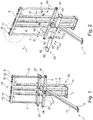
- a base frame 1 comprises, for example, three vertical supports 2-4, a first cross strut 5 and a second cross strut 6, two connecting elements 7, 8, an attachment means 9, 10 and a support leg 11 ( Figures 1 to 3 and 5 to 8) .
- the belt frame 1 is for example for a two-seater vehicle seat (not shown) formed.
- the vertical supports 2-4 are provided in the arranged state on the base frame 1, vertically aligned.
- the vertical supports 2-4 are spaced apart from one another and, for example, are present next to one another parallel to one another.
- attachment means 10 are provided in order to fasten the vertical supports 2-4 in the arranged state to a vehicle (not shown), for example to screw them to a vehicle floor.
- the transverse struts 5, 6 are advantageously provided perpendicular to the vertical supports 2-4 and are preferably connected, in particular non-detachably, to each of the vertical supports 2-4.
- the cross struts 5, 6 are welded to the vertical supports 2-4.
- the cross struts 5, 6 are screwed and / or riveted to the vertical supports 2-4.
- the first cross strut 5 is advantageously mounted with a rear side on a front side 13 of the vertical support 2-4.
- a surface normal of the front side 13 of the vertical supports 2-4 advantageously points in the arranged state of the belt frame 1 on the vehicle in a direction of travel F of the vehicle, in particular in the direction of the front of the vehicle.
- the second cross strut 6 is arranged, for example, on a head region 14 of the belt frame 1 on one of the vertical supports 2-4 or on each of the vertical supports 2-4.
- Sleeve-like attachment elements 15-18 are formed on the second transverse strut 6, which are provided, for example in pairs, to arrange a headrest (not shown).
- the first cross strut 5 is advantageously fastened to the vertical supports 2-4 approximately at the level of a seat surface of a vehicle seat, the vehicle seat including the base frame 1.
- the first cross strut 5 is formed starting from the attachment means 10 in the vertical direction upwards at the level of a first and / or lowermost third of a length of the vertical supports 2-4.
- the connecting elements 7, 8 are for example in the form of a band, for example a steel band.
- the connecting elements 7, 8 connect the first cross strut 5 and the second cross strut 6 to one another.
- the connecting elements 7, 8 are permanently connected to the transverse struts 5, 6, for example welded.
- the connecting elements 7, 8 are provided, for example, aligned parallel to the vertical supports 2-4 and extend, for example, in the vertical direction.
- the connecting elements 7, 8 are provided to keep the cross struts 5, 6 at a defined, e.g. vertical distance from one another, in particular in the event of a crash.
- the connecting elements 7, 8 are intended to define a maximum vertical spacing of the transverse struts 5, 6 from one another, in particular such that the transverse struts 5, 6 from one another do not exceed the maximum vertical spacing in the event of a crash.
- the connecting elements 7, 8 preferably connect ends of the transverse struts 5, 6 to one another.
- fastening screws 19, 20 are formed at the ends of the first cross strut.
- a safety component of a personal restraint system is fastened to the fastening screws 19, 20, e.g. a belt whip 21, 22 with a belt lock ( Figure 3 ) a 3-point belt safety system.
- a device 23 according to the invention is designed as an elongated, in particular angled profile 24.
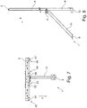
- the profile 24 has, for example, two folds 25, 26 in the form of bends, so that it is present in a zigzag shape in cross section.
- the folds 25, 26 advantageously extend along a longitudinal axis of the profile 24.
- the profile 24 has, for example, a first and a second flat profile section 27, 28, the two profile sections 27, 28 advantageously parallel to one another available.
- the first and second profile sections 27, 28 extend in the arranged state on the belt frame 1 advantageously each in a vertical direction, for example parallel to the longitudinal axis of a vertical support 2-4 and along the longitudinal axis of the profile 24.
- the profile 24 has a third flat profile section 29, which is advantageously provided at an angle to the first and second profile section 27, 28.
- the profile section 29 is advantageously horizontally aligned.
- the profile 24 is available in one piece, for example, with the three profile sections 27 - 29 merging into one another via the bevels 25, 26 ( Figures 2 , 3 ).
- the profile 24 further comprises spaced apart receiving organs in the form of recesses 30-32.
- the recesses 30-32 are, for example, cut out of the profile 24, e.g., lasered.
- the recesses 30-32 are present in particular on the second and third profile sections 28, 29 so that the profile 24 can be placed or pushed onto the vertical supports 2-4 in the horizontal direction.
- the recesses 30-32 are matched in particular to an outer contour of the vertical supports 2 - 4 of the belt frame 1, so that the recesses 30-32 in the arranged state of the device 23 on the belt frame 1, the vertical supports 2 - 4 at least on the front side 13 and on side surfaces 33, 34 in particular completely, for example directly adjacent.
- the recesses 30-32 with edge surfaces 35-37 are advantageously in particular flush and / or positively against the front side 13 and the side surfaces 33, 34 of the vertical supports 2-4.
- a width of the third profile section 29 is greater than a depth of the vertical supports 2-4.
- the third profile section 29 extends opposite to the direction of travel F over a rear edge 38 of the vertical support 2-4.
- a front side 39 of the second profile section 28 in the arranged state of the device 23 on the belt frame 1 is flush with a rear side 40 of the vertical supports 2-4.
- a rear side 41 of the second profile section 28 is flush with the rear side 40 of the vertical supports 2-4 in the arranged state of the profile 24 on the belt frame 1, the rear side 41 being opposite and spaced from the front side 39 of the second profile section 28.
- a distance between the recesses 30-32 along the longitudinal axis of the profile 24 advantageously corresponds to a horizontal distance between the vertical supports 2-4 of the belt frame 1, so that the device 23 can be attached to the belt frame 1 in a comparatively simple and precise manner.
- the distances between the recesses 30-32 and the vertical supports 2-4 correspond, for example, to a grid dimension.
- the device 23 also includes mounting means in the form of U-shaped retaining brackets 42 - 45 which are arranged protruding from the first profile section 27.
- the retaining brackets 42 - 45 are screwed and / or welded to the profile 24, for example, at connection points 46 - 53.
- a distance of a stop 54-57 of the retaining brackets 42-45 from a front side 58 of the second profile section 27 is adjustable, for example, before the assembly of the device 23 on the belt frame 1, whereby at the stop 54-57 a holding catch 59 of a child seat 60 in the arranged state of the Child seat 60 engages the belt frame 1.
- a change in the distance between the stop 54 - 57 and the front side 58 is advantageously prevented when the device 23 is arranged on the belt frame 1, e.g. because the retaining brackets 42 - 45 are welded to the profile 24 after the distance has been set.
- the profile 24 comprises slot-like recesses 61, 62, in which, when the device 23 is arranged on the belt frame 1, the connecting elements 7, 8 are present, engaging.
- the slot-like recess 61, 62 extends on the profile 24, preferably on the second and third profile sections 28, 29.
- the recess 61, 62 advantageously encloses a connecting element 7, 8, for example, positively at least on side surfaces 63, 64 and on a front side 65 of the connecting element 7, 8.
- a flag-like connecting element 66, 67 is cut out of the second profile section 28 and bent forward in the direction of the second profile section 27, in particular bent in the direction of travel F when the profile 24 is arranged on the belt frame 1.
- the connecting elements 66, 67 are present in the arranged state on the belt frame 1 resting on the outer side surface 64 of the connecting elements 7, 8 and are connected to these at assembly points 80, 81, for example screwed with screws 68, 69.
- the device 23 comprises clamping means in the form of connecting plates 70, 71.
- the connecting plates 70, 71 are arranged adjacent to the rear side 40 of the vertical support 2-4 and screwed to the profile 24 via screws 72-75.
- a front edge surface 36 of the recesses 30 - 32 is drawn against the front side 13 of the vertical support 2 - 4 and the device 23 is thus clamped to the belt frame 1.
- the device 23 is arranged on the belt frame 1 by means of two connecting plates 70, 71.
- the device is connected to the belt frame in a clamping manner via a single connecting plate on a single vertical support 2-4. It is also conceivable that the device is connected to the belt frame in a clamping manner on all vertical supports of a belt frame.
- FIG 4 is an enlarged section of the belt frame 1 according to Figure 2 refer to.
- a portion of the head-side cross brace 6 is shown, on which a bore 76 is formed.
- One end 78 of a top tether band 79 of the child seat 60 can be hooked into the bore 76.
- That Belt frame 1 is provided for a two-seater vehicle seat (not shown), for this reason a further bore 77 is formed on the head-side cross strut for attaching a further child seat.
Landscapes
- Engineering & Computer Science (AREA)
- Mechanical Engineering (AREA)
- Aviation & Aerospace Engineering (AREA)
- Transportation (AREA)
- Health & Medical Sciences (AREA)
- Child & Adolescent Psychology (AREA)
- General Health & Medical Sciences (AREA)
- Seats For Vehicles (AREA)
Claims (11)
- Bâti de ceinture (1) pour un siège de véhicule comprenant un dispositif (23) destiné à l'agencement d'un système de retenue de personne dans un véhicule, notamment destiné à l'agencement d'un siège pour enfant (60), afin de mettre en sécurité une personne assise dans le véhicule avec le système de retenue de personne (60) le dispositif (23) étant fixé au bâti de ceinture (1), le bâti de ceinture (1) comportant un arrangement de soutien pourvu d'un soutien vertical (2 - 4) et d'une traverse (5, 6), et le soutien vertical (2 - 4) pouvant, dans l'état agencé de l'arrangement de soutien sur le véhicule, être monté en position debout sur un plancher de véhicule du véhicule, le dispositif (23) étant présent sous la forme d'un profilé allongé (24), le dispositif (23) possédant, le long d'un axe longitudinal du profilé (24), des moyens de montage (42 - 45) servant à la fixation de crans de retenue (59) du système de retenue de personne (60), notamment d'un système de retenue de personne (60) Isofix, les moyens de montage (42 - 45) étant présents espacés les uns des autres le long de l'axe longitudinal du profilé (24) et le dispositif (23) étant présent sous la forme d'un profilé longitudinal (24) en tant que pièce rapportée séparée du bâti de ceinture (1) et pouvant être monté ultérieurement sur le bâti de ceinture (1), caractérisé en ce que le profilé (24) est présent de telle sorte que le profilé (24), dans l'état agencé sur le bâti de ceinture (1), enveloppe le soutien vertical (2 - 4).
- Bâti de ceinture (1) pour un siège de véhicule selon la revendication précédente 1, caractérisé en ce que le profilé (24) est présent sous la forme d'un profilé (24) replié, notamment une bande profilée repliée.
- Bâti de ceinture (1) pour un siège de véhicule selon l'une des revendications précédentes, caractérisé en ce que le dispositif (23) possède des moyens de serrage (70, 71), le dispositif (23), dans l'état agencé sur le bâti de ceinture (1), étant bloqué par les moyens de serrage (70, 71) contre le soutien vertical (2 - 4) du bâti de ceinture (1).
- Bâti de ceinture (1) pour un siège de véhicule selon l'une des revendications précédentes, caractérisé en ce qu'un écart entre un point de maintien (54 - 57) du moyen de montage (42 - 45) et un point d'attache (46 - 53) du moyen de montage (42 - 45) est présent de manière réglable sur le profil (24), le cran de retenue (59) du système de retenue de personne (60), dans l'état agencé, venant en prise au niveau du point de maintien (54 - 57) du moyen de montage (42 - 45).
- Bâti de ceinture (1) pour un siège de véhicule selon l'une des revendications précédentes, caractérisé en ce que le dispositif (23), notamment le profilé (24), possède un pas de grille.
- Bâti de ceinture (1) pour un siège de véhicule selon l'une des revendications précédentes, caractérisé en ce que l'arrangement de soutien possède deux traverses (5, 6), une première traverse (6) se trouvant au niveau d'une extrémité supérieure (14) de l'arrangement de soutien, la première traverse (6) étant configurée pour l'agencement d'un appuie-tête du siège de véhicule, une deuxième traverse (5), vue dans la direction verticale, se trouvant dans une zone centrale de l'arrangement de soutien, des composants (21, 22) d'un système de retenue de personne (60) étant agencés au niveau de la deuxième traverse (5) dans l'état agencé du bâti de ceinture (1) sur le siège de véhicule, la première et la deuxième traverse (5, 6) s'étendant dans la direction horizontale sur l'arrangement de soutien, la première et la deuxième traverse (5, 6), vues en extension verticale, étant reliées l'une à l'autre par un élément en forme de bande (6, 7) au niveau d'une zone extérieure de la première et de la deuxième traverse (5, 6), l'élément en forme de bande (6, 7) possédant des moyens d'attache (80, 81), moyennant quoi le dispositif (23) est bloqué à l'état agencé.
- Bâti de ceinture (1) pour un siège de véhicule selon la revendication précédente 6, caractérisé en ce que le dispositif (23), vu dans une extension verticale de l'arrangement de soutien, est disposé sur le bâti de ceinture (1) dans une zone entre la première et la deuxième traverse (5, 6).
- Bâti de ceinture (1) pour un siège de véhicule selon l'une des revendications précédentes 6 et 7, caractérisé en ce que des moyens de montage (76, 77) servant à la fixation d'une bande de sangle supérieure (79) d'un système de retenue de personne (60) sont présents au niveau de la première traverse (6).
- Bâti de ceinture (1) pour un siège de véhicule selon l'une des revendications précédentes 6 à 8, caractérisé en ce que le bâti de ceinture (1) possède un pas de grille.
- Siège de véhicule et/ou banquette de véhicule comprenant un bâti de ceinture (1) selon l'une des revendications précédentes.
- Véhicule équipé d'un siège de véhicule et/ou d'une banquette de véhicule selon la revendication précédente 10 et/ou d'un bâti de ceinture (1) selon l'une des revendications précédentes 1 à 9.
Priority Applications (1)
| Application Number | Priority Date | Filing Date | Title |
|---|---|---|---|
| SI201830516T SI3375659T1 (sl) | 2017-03-14 | 2018-02-07 | Naprava za namestitev zadrževalnega sistema osebe v vozilu |
Applications Claiming Priority (1)
| Application Number | Priority Date | Filing Date | Title |
|---|---|---|---|
| DE102017105384.0A DE102017105384A1 (de) | 2017-03-14 | 2017-03-14 | Vorrichtung zur Anordnung eines Personenrückhaltesystems in einem Fahrzeug |
Publications (2)
| Publication Number | Publication Date |
|---|---|
| EP3375659A1 EP3375659A1 (fr) | 2018-09-19 |
| EP3375659B1 true EP3375659B1 (fr) | 2021-09-22 |
Family
ID=61187123
Family Applications (1)
| Application Number | Title | Priority Date | Filing Date |
|---|---|---|---|
| EP18155437.9A Active EP3375659B1 (fr) | 2017-03-14 | 2018-02-07 | Dispositif destiné à agencer un système de retenue de passager dans un véhicule |
Country Status (5)
| Country | Link |
|---|---|
| EP (1) | EP3375659B1 (fr) |
| DE (1) | DE102017105384A1 (fr) |
| ES (1) | ES2901219T3 (fr) |
| HU (1) | HUE057091T2 (fr) |
| SI (1) | SI3375659T1 (fr) |
Families Citing this family (2)
| Publication number | Priority date | Publication date | Assignee | Title |
|---|---|---|---|---|
| DE102021114201A1 (de) * | 2021-06-01 | 2022-12-01 | Aguti Produktentwicklung & Design Gmbh | Gurtgestell und Fahrzeugsitz |
| DE102022102686A1 (de) | 2022-02-04 | 2023-08-10 | Aguti Produktentwicklung & Design Gmbh | Gurtgestell für einen Fahrzeugsitz |
Citations (14)
| Publication number | Priority date | Publication date | Assignee | Title |
|---|---|---|---|---|
| US3885810A (en) | 1972-01-10 | 1975-05-27 | John J Chika | Seat supporting structure for fast moving vehicles |
| DE9314859U1 (de) | 1993-09-30 | 1994-01-05 | Sportscraft-Freizeitprodukte GmbH, 82152 Planegg | Klappsitzbank mit Rückhaltesystem, insbesondere für Wohnmobile |
| DE20008510U1 (de) | 2000-05-11 | 2000-10-19 | Unex-Metall GmbH, 96194 Walsdorf | Einstellung zur Höhenverstellung eines Fahrzeug-Sicherheitsgurtes |
| US20020109381A1 (en) | 2001-02-15 | 2002-08-15 | Duncan Gary L. | Dinette child safety seat attachment system |
| US20040080194A1 (en) | 2002-10-28 | 2004-04-29 | Johnson Controls Technology Company | Mechanical attachment of anchorage |
| DE60302129T2 (de) | 2002-12-04 | 2006-07-13 | Durisotti, S.A. | Faltbare Sicherheitsbank |
| DE102006007384A1 (de) | 2006-02-17 | 2007-07-05 | Unex-Metall Gmbh | Befestigungseinrichtung für einen Kinder- oder Babysitz auf einem nachgerüsteten Sitz eines Kraftfahrzeuges |
| DE102006007383A1 (de) | 2006-02-17 | 2007-09-06 | Unex-Metall Gmbh | Rückhaltesystem für eine Sitzbank im Wohnbereich eines Wohnmobils |
| DE102010055198A1 (de) | 2010-12-20 | 2012-06-21 | Aguti Produktentwicklung & Design Gmbh | Vorrichtung zur Anbringung eines Personenrückhaltesystems mit einer Sicherheitsgurtanordnung sowie Bodenplatte eines Fahrzeugs |
| FR3004151A1 (fr) | 2013-04-09 | 2014-10-10 | Renault Sa | Systeme de fixation d'un siege pour enfant sur un siege de vehicule |
| DE102014003966A1 (de) | 2014-03-20 | 2015-09-24 | Aguti Produktentwicklung & Design Gmbh | Vorrichtung zur Anordnung eines Personenrückhaltesystems zur Sicherung von Personen in einem Verkehrsmittel und Verkehrsmittel |
| WO2016046056A1 (fr) | 2014-09-25 | 2016-03-31 | Johnson Controls Gmbh | Dispositif de fixation pour siège auto pour enfant, en particulier sur un siège de véhicule |
| US20160362026A1 (en) | 2015-06-11 | 2016-12-15 | Toyota Boshoku Kabushiki Kaisha | Vehicle seat |
| EP3366511A1 (fr) | 2017-02-23 | 2018-08-29 | Aguti Produktentwicklung & Design Gmbh | Ancrage ceinture pour un siège de véhicule ou une banquette de véhicule |
Family Cites Families (1)
| Publication number | Priority date | Publication date | Assignee | Title |
|---|---|---|---|---|
| DE29721468U1 (de) | 1997-08-07 | 1998-02-12 | Recaro GmbH & Co., 73230 Kirchheim | Kinderfahrzeugsitz |
-
2017
- 2017-03-14 DE DE102017105384.0A patent/DE102017105384A1/de active Pending
-
2018
- 2018-02-07 ES ES18155437T patent/ES2901219T3/es active Active
- 2018-02-07 SI SI201830516T patent/SI3375659T1/sl unknown
- 2018-02-07 EP EP18155437.9A patent/EP3375659B1/fr active Active
- 2018-02-07 HU HUE18155437A patent/HUE057091T2/hu unknown
Patent Citations (15)
| Publication number | Priority date | Publication date | Assignee | Title |
|---|---|---|---|---|
| US3885810A (en) | 1972-01-10 | 1975-05-27 | John J Chika | Seat supporting structure for fast moving vehicles |
| DE9314859U1 (de) | 1993-09-30 | 1994-01-05 | Sportscraft-Freizeitprodukte GmbH, 82152 Planegg | Klappsitzbank mit Rückhaltesystem, insbesondere für Wohnmobile |
| DE20008510U1 (de) | 2000-05-11 | 2000-10-19 | Unex-Metall GmbH, 96194 Walsdorf | Einstellung zur Höhenverstellung eines Fahrzeug-Sicherheitsgurtes |
| US20020109381A1 (en) | 2001-02-15 | 2002-08-15 | Duncan Gary L. | Dinette child safety seat attachment system |
| US20040080194A1 (en) | 2002-10-28 | 2004-04-29 | Johnson Controls Technology Company | Mechanical attachment of anchorage |
| DE60302129T2 (de) | 2002-12-04 | 2006-07-13 | Durisotti, S.A. | Faltbare Sicherheitsbank |
| DE102006007384A1 (de) | 2006-02-17 | 2007-07-05 | Unex-Metall Gmbh | Befestigungseinrichtung für einen Kinder- oder Babysitz auf einem nachgerüsteten Sitz eines Kraftfahrzeuges |
| DE102006007383A1 (de) | 2006-02-17 | 2007-09-06 | Unex-Metall Gmbh | Rückhaltesystem für eine Sitzbank im Wohnbereich eines Wohnmobils |
| DE102010055198A1 (de) | 2010-12-20 | 2012-06-21 | Aguti Produktentwicklung & Design Gmbh | Vorrichtung zur Anbringung eines Personenrückhaltesystems mit einer Sicherheitsgurtanordnung sowie Bodenplatte eines Fahrzeugs |
| FR3004151A1 (fr) | 2013-04-09 | 2014-10-10 | Renault Sa | Systeme de fixation d'un siege pour enfant sur un siege de vehicule |
| DE102014003966A1 (de) | 2014-03-20 | 2015-09-24 | Aguti Produktentwicklung & Design Gmbh | Vorrichtung zur Anordnung eines Personenrückhaltesystems zur Sicherung von Personen in einem Verkehrsmittel und Verkehrsmittel |
| WO2016046056A1 (fr) | 2014-09-25 | 2016-03-31 | Johnson Controls Gmbh | Dispositif de fixation pour siège auto pour enfant, en particulier sur un siège de véhicule |
| US20160362026A1 (en) | 2015-06-11 | 2016-12-15 | Toyota Boshoku Kabushiki Kaisha | Vehicle seat |
| EP3366511A1 (fr) | 2017-02-23 | 2018-08-29 | Aguti Produktentwicklung & Design Gmbh | Ancrage ceinture pour un siège de véhicule ou une banquette de véhicule |
| EP3366511B1 (fr) | 2017-02-23 | 2020-04-29 | Aguti Produktentwicklung & Design Gmbh | Ancrage ceinture pour un siège de véhicule ou une banquette de véhicule |
Also Published As
| Publication number | Publication date |
|---|---|
| DE102017105384A1 (de) | 2018-09-20 |
| HUE057091T2 (hu) | 2022-04-28 |
| ES2901219T3 (es) | 2022-03-21 |
| SI3375659T1 (sl) | 2022-02-28 |
| EP3375659A1 (fr) | 2018-09-19 |
Similar Documents
| Publication | Publication Date | Title |
|---|---|---|
| EP3870484B1 (fr) | Structure de siège de véhicule et procédé de montage d'une structure de siège de véhicule | |
| WO2018011052A1 (fr) | Dispositif de réglage longitudinal et siège de véhicule | |
| DE10261393B4 (de) | Höhenverstellbares Laderaumbodensystem | |
| WO2015082537A1 (fr) | Ensemble siège pourvu d'un dispositif de verrou de ceinture | |
| EP3539818A1 (fr) | Châssis ceinture pour siège de véhicule ou banquette de véhicule et ensemble de siège de véhicule | |
| EP3508373B1 (fr) | Support de ceinture pour un siège de véhicule | |
| EP3398840B1 (fr) | Dispositif destiné à agencer un système de retenue des personnes dans un véhicule | |
| EP2945828B1 (fr) | Dispositif de montage pour un élément d'habillage de paroi latérale d'un véhicule ferroviaire | |
| EP3375659A1 (fr) | Dispositif destiné à agencer un système de retenue de passager dans un véhicule | |
| EP3366511B1 (fr) | Ancrage ceinture pour un siège de véhicule ou une banquette de véhicule | |
| DE102024125190A1 (de) | Verbesserte befestigungsklammer | |
| EP2945827B1 (fr) | Dispositif de montage pour un élément d'habillage de paroi latérale d'un véhicule ferroviaire | |
| DE102016117888A1 (de) | Vorrichtung zur Anordnung eines Personenrückhaltesystems | |
| EP3238989A1 (fr) | Dispositif d'agencement d'un système de retenue de personne dans un moyen de transport, agencement de siège de personne et moyen de transport | |
| EP3238987B1 (fr) | Dispositif d'agencement d'un système de retenue de personne dans un moyen de transport, agencement de siège de personne et moyen de transport | |
| EP4223596B1 (fr) | Cadre de ceinture pour siège de véhicule | |
| DE4142789C1 (en) | Vehicle seat back rest - has cushion carrier connected on both sides to bars via profiled rails | |
| DE19647805C1 (de) | Vorrichtung zum Absorbieren der auf einen Sicherheitsgurt übertragenen Aufprallkräfte | |
| EP0642957A2 (fr) | Dispositif de renvoi latéral réglable en hauteur pour ceintures de sécurité | |
| DE202010014696U1 (de) | Windschott | |
| DE202017007028U1 (de) | Gurtgestell für einen Fahrzeugsitz | |
| EP4223595A1 (fr) | Cadre de ceinture pour siège de véhicule | |
| EP4269185A1 (fr) | Véhicule de loisirs, en particulier camping-car, et dispositif de support de ceinture | |
| DE102021123829A1 (de) | Grundgestell einer Sitzanordnung, Fahrzeugboden-Struktur und Fahrzeug | |
| EP3238988A1 (fr) | Dispositif d'agencement d'un système de retenue de personne |
Legal Events
| Date | Code | Title | Description |
|---|---|---|---|
| PUAI | Public reference made under article 153(3) epc to a published international application that has entered the european phase |
Free format text: ORIGINAL CODE: 0009012 |
|
| STAA | Information on the status of an ep patent application or granted ep patent |
Free format text: STATUS: THE APPLICATION HAS BEEN PUBLISHED |
|
| AK | Designated contracting states |
Kind code of ref document: A1 Designated state(s): AL AT BE BG CH CY CZ DE DK EE ES FI FR GB GR HR HU IE IS IT LI LT LU LV MC MK MT NL NO PL PT RO RS SE SI SK SM TR |
|
| AX | Request for extension of the european patent |
Extension state: BA ME |
|
| STAA | Information on the status of an ep patent application or granted ep patent |
Free format text: STATUS: REQUEST FOR EXAMINATION WAS MADE |
|
| 17P | Request for examination filed |
Effective date: 20190315 |
|
| RBV | Designated contracting states (corrected) |
Designated state(s): AL AT BE BG CH CY CZ DE DK EE ES FI FR GB GR HR HU IE IS IT LI LT LU LV MC MK MT NL NO PL PT RO RS SE SI SK SM TR |
|
| STAA | Information on the status of an ep patent application or granted ep patent |
Free format text: STATUS: EXAMINATION IS IN PROGRESS |
|
| TPAC | Observations filed by third parties |
Free format text: ORIGINAL CODE: EPIDOSNTIPA |
|
| 17Q | First examination report despatched |
Effective date: 20200629 |
|
| GRAP | Despatch of communication of intention to grant a patent |
Free format text: ORIGINAL CODE: EPIDOSNIGR1 |
|
| STAA | Information on the status of an ep patent application or granted ep patent |
Free format text: STATUS: GRANT OF PATENT IS INTENDED |
|
| GRAJ | Information related to disapproval of communication of intention to grant by the applicant or resumption of examination proceedings by the epo deleted |
Free format text: ORIGINAL CODE: EPIDOSDIGR1 |
|
| STAA | Information on the status of an ep patent application or granted ep patent |
Free format text: STATUS: EXAMINATION IS IN PROGRESS |
|
| INTG | Intention to grant announced |
Effective date: 20210120 |
|
| INTC | Intention to grant announced (deleted) | ||
| GRAP | Despatch of communication of intention to grant a patent |
Free format text: ORIGINAL CODE: EPIDOSNIGR1 |
|
| STAA | Information on the status of an ep patent application or granted ep patent |
Free format text: STATUS: GRANT OF PATENT IS INTENDED |
|
| INTG | Intention to grant announced |
Effective date: 20210409 |
|
| GRAS | Grant fee paid |
Free format text: ORIGINAL CODE: EPIDOSNIGR3 |
|
| GRAA | (expected) grant |
Free format text: ORIGINAL CODE: 0009210 |
|
| STAA | Information on the status of an ep patent application or granted ep patent |
Free format text: STATUS: THE PATENT HAS BEEN GRANTED |
|
| AK | Designated contracting states |
Kind code of ref document: B1 Designated state(s): AL AT BE BG CH CY CZ DE DK EE ES FI FR GB GR HR HU IE IS IT LI LT LU LV MC MK MT NL NO PL PT RO RS SE SI SK SM TR |
|
| REG | Reference to a national code |
Ref country code: GB Ref legal event code: FG4D Free format text: NOT ENGLISH |
|
| REG | Reference to a national code |
Ref country code: IE Ref legal event code: FG4D Free format text: LANGUAGE OF EP DOCUMENT: GERMAN |
|
| REG | Reference to a national code |
Ref country code: DE Ref legal event code: R096 Ref document number: 502018007130 Country of ref document: DE |
|
| REG | Reference to a national code |
Ref country code: CH Ref legal event code: EP Ref country code: AT Ref legal event code: REF Ref document number: 1432079 Country of ref document: AT Kind code of ref document: T Effective date: 20211015 |
|
| REG | Reference to a national code |
Ref country code: NO Ref legal event code: T2 Effective date: 20210922 |
|
| REG | Reference to a national code |
Ref country code: LT Ref legal event code: MG9D |
|
| REG | Reference to a national code |
Ref country code: SE Ref legal event code: TRGR |
|
| REG | Reference to a national code |
Ref country code: NL Ref legal event code: MP Effective date: 20210922 |
|
| PG25 | Lapsed in a contracting state [announced via postgrant information from national office to epo] |
Ref country code: HR Free format text: LAPSE BECAUSE OF FAILURE TO SUBMIT A TRANSLATION OF THE DESCRIPTION OR TO PAY THE FEE WITHIN THE PRESCRIBED TIME-LIMIT Effective date: 20210922 Ref country code: FI Free format text: LAPSE BECAUSE OF FAILURE TO SUBMIT A TRANSLATION OF THE DESCRIPTION OR TO PAY THE FEE WITHIN THE PRESCRIBED TIME-LIMIT Effective date: 20210922 Ref country code: RS Free format text: LAPSE BECAUSE OF FAILURE TO SUBMIT A TRANSLATION OF THE DESCRIPTION OR TO PAY THE FEE WITHIN THE PRESCRIBED TIME-LIMIT Effective date: 20210922 Ref country code: BG Free format text: LAPSE BECAUSE OF FAILURE TO SUBMIT A TRANSLATION OF THE DESCRIPTION OR TO PAY THE FEE WITHIN THE PRESCRIBED TIME-LIMIT Effective date: 20211222 Ref country code: LT Free format text: LAPSE BECAUSE OF FAILURE TO SUBMIT A TRANSLATION OF THE DESCRIPTION OR TO PAY THE FEE WITHIN THE PRESCRIBED TIME-LIMIT Effective date: 20210922 |
|
| PG25 | Lapsed in a contracting state [announced via postgrant information from national office to epo] |
Ref country code: LV Free format text: LAPSE BECAUSE OF FAILURE TO SUBMIT A TRANSLATION OF THE DESCRIPTION OR TO PAY THE FEE WITHIN THE PRESCRIBED TIME-LIMIT Effective date: 20210922 Ref country code: GR Free format text: LAPSE BECAUSE OF FAILURE TO SUBMIT A TRANSLATION OF THE DESCRIPTION OR TO PAY THE FEE WITHIN THE PRESCRIBED TIME-LIMIT Effective date: 20211223 |
|
| REG | Reference to a national code |
Ref country code: ES Ref legal event code: FG2A Ref document number: 2901219 Country of ref document: ES Kind code of ref document: T3 Effective date: 20220321 |
|
| REG | Reference to a national code |
Ref country code: HU Ref legal event code: AG4A Ref document number: E057091 Country of ref document: HU |
|
| REG | Reference to a national code |
Ref country code: DE Ref legal event code: R026 Ref document number: 502018007130 Country of ref document: DE |
|
| PLBI | Opposition filed |
Free format text: ORIGINAL CODE: 0009260 |
|
| PG25 | Lapsed in a contracting state [announced via postgrant information from national office to epo] |
Ref country code: IS Free format text: LAPSE BECAUSE OF FAILURE TO SUBMIT A TRANSLATION OF THE DESCRIPTION OR TO PAY THE FEE WITHIN THE PRESCRIBED TIME-LIMIT Effective date: 20220122 Ref country code: SK Free format text: LAPSE BECAUSE OF FAILURE TO SUBMIT A TRANSLATION OF THE DESCRIPTION OR TO PAY THE FEE WITHIN THE PRESCRIBED TIME-LIMIT Effective date: 20210922 Ref country code: RO Free format text: LAPSE BECAUSE OF FAILURE TO SUBMIT A TRANSLATION OF THE DESCRIPTION OR TO PAY THE FEE WITHIN THE PRESCRIBED TIME-LIMIT Effective date: 20210922 Ref country code: PT Free format text: LAPSE BECAUSE OF FAILURE TO SUBMIT A TRANSLATION OF THE DESCRIPTION OR TO PAY THE FEE WITHIN THE PRESCRIBED TIME-LIMIT Effective date: 20220124 Ref country code: PL Free format text: LAPSE BECAUSE OF FAILURE TO SUBMIT A TRANSLATION OF THE DESCRIPTION OR TO PAY THE FEE WITHIN THE PRESCRIBED TIME-LIMIT Effective date: 20210922 Ref country code: NL Free format text: LAPSE BECAUSE OF FAILURE TO SUBMIT A TRANSLATION OF THE DESCRIPTION OR TO PAY THE FEE WITHIN THE PRESCRIBED TIME-LIMIT Effective date: 20210922 Ref country code: EE Free format text: LAPSE BECAUSE OF FAILURE TO SUBMIT A TRANSLATION OF THE DESCRIPTION OR TO PAY THE FEE WITHIN THE PRESCRIBED TIME-LIMIT Effective date: 20210922 Ref country code: AL Free format text: LAPSE BECAUSE OF FAILURE TO SUBMIT A TRANSLATION OF THE DESCRIPTION OR TO PAY THE FEE WITHIN THE PRESCRIBED TIME-LIMIT Effective date: 20210922 |
|
| 26 | Opposition filed |
Opponent name: REIKON GMBH & CO. KG Effective date: 20220513 |
|
| PLBI | Opposition filed |
Free format text: ORIGINAL CODE: 0009260 |
|
| PLAB | Opposition data, opponent's data or that of the opponent's representative modified |
Free format text: ORIGINAL CODE: 0009299OPPO |
|
| PLAX | Notice of opposition and request to file observation + time limit sent |
Free format text: ORIGINAL CODE: EPIDOSNOBS2 |
|
| 26 | Opposition filed |
Opponent name: ERWIN HYMER GROUP SE Effective date: 20220621 |
|
| PG25 | Lapsed in a contracting state [announced via postgrant information from national office to epo] |
Ref country code: DK Free format text: LAPSE BECAUSE OF FAILURE TO SUBMIT A TRANSLATION OF THE DESCRIPTION OR TO PAY THE FEE WITHIN THE PRESCRIBED TIME-LIMIT Effective date: 20210922 |
|
| R26 | Opposition filed (corrected) |
Opponent name: ERWIN HYMER GROUP SE Effective date: 20220621 |
|
| PG25 | Lapsed in a contracting state [announced via postgrant information from national office to epo] |
Ref country code: MC Free format text: LAPSE BECAUSE OF FAILURE TO SUBMIT A TRANSLATION OF THE DESCRIPTION OR TO PAY THE FEE WITHIN THE PRESCRIBED TIME-LIMIT Effective date: 20210922 |
|
| PLBB | Reply of patent proprietor to notice(s) of opposition received |
Free format text: ORIGINAL CODE: EPIDOSNOBS3 |
|
| REG | Reference to a national code |
Ref country code: CH Ref legal event code: PL |
|
| REG | Reference to a national code |
Ref country code: BE Ref legal event code: MM Effective date: 20220228 |
|
| PG25 | Lapsed in a contracting state [announced via postgrant information from national office to epo] |
Ref country code: LU Free format text: LAPSE BECAUSE OF NON-PAYMENT OF DUE FEES Effective date: 20220207 |
|
| PG25 | Lapsed in a contracting state [announced via postgrant information from national office to epo] |
Ref country code: LI Free format text: LAPSE BECAUSE OF NON-PAYMENT OF DUE FEES Effective date: 20220228 Ref country code: IE Free format text: LAPSE BECAUSE OF NON-PAYMENT OF DUE FEES Effective date: 20220207 Ref country code: CH Free format text: LAPSE BECAUSE OF NON-PAYMENT OF DUE FEES Effective date: 20220228 |
|
| PG25 | Lapsed in a contracting state [announced via postgrant information from national office to epo] |
Ref country code: BE Free format text: LAPSE BECAUSE OF NON-PAYMENT OF DUE FEES Effective date: 20220228 |
|
| PGFP | Annual fee paid to national office [announced via postgrant information from national office to epo] |
Ref country code: NO Payment date: 20230217 Year of fee payment: 6 Ref country code: FR Payment date: 20230217 Year of fee payment: 6 Ref country code: ES Payment date: 20230317 Year of fee payment: 6 Ref country code: CZ Payment date: 20230126 Year of fee payment: 6 Ref country code: AT Payment date: 20230215 Year of fee payment: 6 |
|
| PGFP | Annual fee paid to national office [announced via postgrant information from national office to epo] |
Ref country code: SI Payment date: 20230126 Year of fee payment: 6 Ref country code: SE Payment date: 20230220 Year of fee payment: 6 Ref country code: GB Payment date: 20230221 Year of fee payment: 6 Ref country code: HU Payment date: 20230203 Year of fee payment: 6 |
|
| P01 | Opt-out of the competence of the unified patent court (upc) registered |
Effective date: 20230523 |
|
| PLAB | Opposition data, opponent's data or that of the opponent's representative modified |
Free format text: ORIGINAL CODE: 0009299OPPO |
|
| R26 | Opposition filed (corrected) |
Opponent name: ERWIN HYMER GROUP SE Effective date: 20220621 |
|
| PG25 | Lapsed in a contracting state [announced via postgrant information from national office to epo] |
Ref country code: SM Free format text: LAPSE BECAUSE OF FAILURE TO SUBMIT A TRANSLATION OF THE DESCRIPTION OR TO PAY THE FEE WITHIN THE PRESCRIBED TIME-LIMIT Effective date: 20210922 Ref country code: MK Free format text: LAPSE BECAUSE OF FAILURE TO SUBMIT A TRANSLATION OF THE DESCRIPTION OR TO PAY THE FEE WITHIN THE PRESCRIBED TIME-LIMIT Effective date: 20210922 Ref country code: CY Free format text: LAPSE BECAUSE OF FAILURE TO SUBMIT A TRANSLATION OF THE DESCRIPTION OR TO PAY THE FEE WITHIN THE PRESCRIBED TIME-LIMIT Effective date: 20210922 |
|
| PG25 | Lapsed in a contracting state [announced via postgrant information from national office to epo] |
Ref country code: MT Free format text: LAPSE BECAUSE OF FAILURE TO SUBMIT A TRANSLATION OF THE DESCRIPTION OR TO PAY THE FEE WITHIN THE PRESCRIBED TIME-LIMIT Effective date: 20210922 |
|
| REG | Reference to a national code |
Ref country code: SE Ref legal event code: EUG |
|
| REG | Reference to a national code |
Ref country code: DE Ref legal event code: R100 Ref document number: 502018007130 Country of ref document: DE Ref country code: AT Ref legal event code: MM01 Ref document number: 1432079 Country of ref document: AT Kind code of ref document: T Effective date: 20240207 |
|
| GBPC | Gb: european patent ceased through non-payment of renewal fee |
Effective date: 20240207 |
|
| PG25 | Lapsed in a contracting state [announced via postgrant information from national office to epo] |
Ref country code: CZ Free format text: LAPSE BECAUSE OF NON-PAYMENT OF DUE FEES Effective date: 20240207 |
|
| PG25 | Lapsed in a contracting state [announced via postgrant information from national office to epo] |
Ref country code: AT Free format text: LAPSE BECAUSE OF NON-PAYMENT OF DUE FEES Effective date: 20240207 |
|
| PG25 | Lapsed in a contracting state [announced via postgrant information from national office to epo] |
Ref country code: HU Free format text: LAPSE BECAUSE OF NON-PAYMENT OF DUE FEES Effective date: 20240208 Ref country code: SI Free format text: LAPSE BECAUSE OF NON-PAYMENT OF DUE FEES Effective date: 20240208 |
|
| PG25 | Lapsed in a contracting state [announced via postgrant information from national office to epo] |
Ref country code: SI Free format text: LAPSE BECAUSE OF NON-PAYMENT OF DUE FEES Effective date: 20240208 Ref country code: NO Free format text: LAPSE BECAUSE OF NON-PAYMENT OF DUE FEES Effective date: 20240229 Ref country code: HU Free format text: LAPSE BECAUSE OF NON-PAYMENT OF DUE FEES Effective date: 20240208 Ref country code: CZ Free format text: LAPSE BECAUSE OF NON-PAYMENT OF DUE FEES Effective date: 20240207 Ref country code: AT Free format text: LAPSE BECAUSE OF NON-PAYMENT OF DUE FEES Effective date: 20240207 |
|
| PLCK | Communication despatched that opposition was rejected |
Free format text: ORIGINAL CODE: EPIDOSNREJ1 |
|
| PG25 | Lapsed in a contracting state [announced via postgrant information from national office to epo] |
Ref country code: GB Free format text: LAPSE BECAUSE OF NON-PAYMENT OF DUE FEES Effective date: 20240207 |
|
| PG25 | Lapsed in a contracting state [announced via postgrant information from national office to epo] |
Ref country code: FR Free format text: LAPSE BECAUSE OF NON-PAYMENT OF DUE FEES Effective date: 20240229 |
|
| PG25 | Lapsed in a contracting state [announced via postgrant information from national office to epo] |
Ref country code: GB Free format text: LAPSE BECAUSE OF NON-PAYMENT OF DUE FEES Effective date: 20240207 Ref country code: FR Free format text: LAPSE BECAUSE OF NON-PAYMENT OF DUE FEES Effective date: 20240229 |
|
| PLBN | Opposition rejected |
Free format text: ORIGINAL CODE: 0009273 |
|
| STAA | Information on the status of an ep patent application or granted ep patent |
Free format text: STATUS: OPPOSITION REJECTED |
|
| REG | Reference to a national code |
Ref country code: DE Ref legal event code: R082 Ref document number: 502018007130 Country of ref document: DE Representative=s name: RAVENSPAT PATENTANWAELTE PARTNERSCHAFT MBB, DE |
|
| 27O | Opposition rejected |
Effective date: 20241015 |
|
| REG | Reference to a national code |
Ref country code: ES Ref legal event code: FD2A Effective date: 20250327 |
|
| PG25 | Lapsed in a contracting state [announced via postgrant information from national office to epo] |
Ref country code: ES Free format text: LAPSE BECAUSE OF NON-PAYMENT OF DUE FEES Effective date: 20240208 |
|
| PG25 | Lapsed in a contracting state [announced via postgrant information from national office to epo] |
Ref country code: SE Free format text: LAPSE BECAUSE OF NON-PAYMENT OF DUE FEES Effective date: 20240208 |
|
| PG25 | Lapsed in a contracting state [announced via postgrant information from national office to epo] |
Ref country code: TR Free format text: LAPSE BECAUSE OF FAILURE TO SUBMIT A TRANSLATION OF THE DESCRIPTION OR TO PAY THE FEE WITHIN THE PRESCRIBED TIME-LIMIT Effective date: 20210922 |
|
| PGFP | Annual fee paid to national office [announced via postgrant information from national office to epo] |
Ref country code: DE Payment date: 20260217 Year of fee payment: 9 |
|
| PGFP | Annual fee paid to national office [announced via postgrant information from national office to epo] |
Ref country code: IT Payment date: 20260227 Year of fee payment: 9 |