EP3375667A1 - Porte-vélo - Google Patents
Porte-vélo Download PDFInfo
- Publication number
- EP3375667A1 EP3375667A1 EP18161295.3A EP18161295A EP3375667A1 EP 3375667 A1 EP3375667 A1 EP 3375667A1 EP 18161295 A EP18161295 A EP 18161295A EP 3375667 A1 EP3375667 A1 EP 3375667A1
- Authority
- EP
- European Patent Office
- Prior art keywords
- front wheel
- rail
- frame
- bicycle
- central frame
- Prior art date
- Legal status (The legal status is an assumption and is not a legal conclusion. Google has not performed a legal analysis and makes no representation as to the accuracy of the status listed.)
- Granted
Links
Images


Classifications
-
- B—PERFORMING OPERATIONS; TRANSPORTING
- B60—VEHICLES IN GENERAL
- B60R—VEHICLES, VEHICLE FITTINGS, OR VEHICLE PARTS, NOT OTHERWISE PROVIDED FOR
- B60R9/00—Supplementary fittings on vehicle exterior for carrying loads, e.g. luggage, sports gear or the like
- B60R9/08—Supplementary fittings on vehicle exterior for carrying loads, e.g. luggage, sports gear or the like specially adapted for sports gear
- B60R9/10—Supplementary fittings on vehicle exterior for carrying loads, e.g. luggage, sports gear or the like specially adapted for sports gear for cycles
-
- B—PERFORMING OPERATIONS; TRANSPORTING
- B60—VEHICLES IN GENERAL
- B60R—VEHICLES, VEHICLE FITTINGS, OR VEHICLE PARTS, NOT OTHERWISE PROVIDED FOR
- B60R9/00—Supplementary fittings on vehicle exterior for carrying loads, e.g. luggage, sports gear or the like
- B60R9/04—Carriers associated with vehicle roof
- B60R9/048—Carriers characterised by article-gripping, -covering,-retaining, or -locking means
-
- B—PERFORMING OPERATIONS; TRANSPORTING
- B60—VEHICLES IN GENERAL
- B60R—VEHICLES, VEHICLE FITTINGS, OR VEHICLE PARTS, NOT OTHERWISE PROVIDED FOR
- B60R9/00—Supplementary fittings on vehicle exterior for carrying loads, e.g. luggage, sports gear or the like
- B60R9/06—Supplementary fittings on vehicle exterior for carrying loads, e.g. luggage, sports gear or the like at vehicle front or rear
-
- B—PERFORMING OPERATIONS; TRANSPORTING
- B60—VEHICLES IN GENERAL
- B60R—VEHICLES, VEHICLE FITTINGS, OR VEHICLE PARTS, NOT OTHERWISE PROVIDED FOR
- B60R9/00—Supplementary fittings on vehicle exterior for carrying loads, e.g. luggage, sports gear or the like
- B60R9/08—Supplementary fittings on vehicle exterior for carrying loads, e.g. luggage, sports gear or the like specially adapted for sports gear
Definitions
- This invention relates to an apparatus for connecting to a motor vehicle and for carrying one or more bicycles.
- a bicycle rack is a device carried by a vehicle that is used to carry one or more bicycles on the exterior of the vehicle in a safe manner.
- Platform style bicycle racks are located behind a vehicle and provide a low loading position that is easier to access than other options and with less risk of damage to the vehicle.
- Bicycles can vary in wheel size, wheelbase, frame shapes and sizes and tyre widths which all present problems for bicycle racks. Wheel sizes can vary from 400mm to 740mm. Tyre width can vary from 19mm to 100mm. Wheelbase can vary from 750mm to 1200mm. Some bicycle racks can weigh more than 20kg which is difficult for an average user to lift and manoeuvre.
- United States of America patent application US 2008/0164292 discloses a bicycle carrier for a vehicle including a frame, a crossbar assembly, a wheel tray, and a swing arm pivotally secured to the crossbar assembly.
- the wheels of the bicycle are positioned in the tray and secured by a tray coupling to restrain lateral movement.
- Two trays may be secured to the crossbar assembly to each receive a wheel of the bicycle.
- the swing arm pivots on the crossbar assembly and includes a shoe which engages the bicycle wheel.
- a shoe coupling secures the bicycle wheel to the swing arm.
- Two swing arms could be pivotally secured to the crossbar assembly each to engage a bicycle wheel.
- the frame may include a drawbar for insertion into the receiver of a trailer hitch. Additional crossbar assemblies could be secured to the frame to accommodate multiple bicycles.
- apparatus for connecting to a motor vehicle and for carrying one or more bicycles
- the apparatus comprising a central frame for connecting to a motor vehicle, a rail connected to the central frame and aligned perpendicular to the central frame, a rear wheel connector connected to the rail at one end thereof and for connecting to a rear wheel of a bicycle, a front wheel stop connected to the rail for bracing against a front wheel of a bicycle, and a front wheel connector rotationally connected to the rail at an opposite end of the rail to the rear wheel connector and for connecting to a front wheel of a bicycle, characterised in that the apparatus further comprises a stop connected to the front wheel connector and for preventing rotation of the front wheel connector beyond a specific point.
- a bicycle rack that can be used on a motor vehicle that is both space efficient and mounts one or more bicycles in a manner that is easily adaptable to different sizes of bicycle while also protecting the bicycle and vehicle from any damage.
- the bicycle rack can be easily connected to a vehicle using the central frame of the bicycle rack and the relatively small number of components of the bicycle rack result in a simple and lightweight construction.
- the bicycle rack does not need to take up much space in storage and can be constructed small enough to fit into the boot of a vehicle.
- the stop which prevents rotation of the front wheel connector beyond a specific point, ensures the safe gripping of the most bicycle types; bicycles with small and large wheels as well as those with mudguards are all held securely in place.
- the upper clamping point is away from the frame or brake callipers.
- the bicycle rack further comprises a second rail connected to the central frame and aligned perpendicular to the central frame and parallel and spaced apart from the first rail, a rear wheel connector connected to the second rail at one end thereof and for connecting to a rear wheel of a bicycle, a front wheel stop connected to the second rail for bracing against a front wheel of a bicycle, and a front wheel connector rotationally connected to the second rail at an opposite end of the second rail to the rear wheel connector and for connecting to a front wheel of a bicycle.
- the second rail is connected to the central frame in opposite orientation to the first rail such that one end of the second rail is adjacent to the opposite end of the first rail.
- the bicycle rack is preferably constructed with two parallel rails that are orientated so that two bicycles can be carried by the bicycle rack with the two bicycles facing in opposite directions. This reduces the space required between the two bicycles and makes for a more compact design of bicycle rack.
- the front wheel connector mounts a front wheel clamp on one end of the front wheel connector, the front wheel connector rotationally connected to the respective rail at the opposite end to the front wheel clamp.
- the front wheel clamp comprises a hook for looping over a front wheel of a bicycle.
- the front wheel connector and the front wheel clamp are extendable in length and lockable at a plurality of different lengths.
- the front wheel connector and the clamp are preferably constructed so that their length is adjustable and there is a clamp in the form of a hook located at the free end of the front wheel connector, which allows the front wheel connector (which is rotationally connected to its rail) to be rotated into position onto a front wheel of a bicycle and then have its length adjusted without damaging the bicycle or the vehicle mounting the bicycle rack.
- the central frame includes a latching mechanism at one end thereof, the latching mechanism for locking the central frame to a receiver of a vehicle.
- the latching mechanism is located internally within the central frame and includes a moveable latch that is biased to move and extend out of the central frame.
- the bicycle rack preferably has a latching mechanism located internally within the central frame of the bicycle rack that includes a biased latch that is biased to move outwards from the interior of the central frame.
- the central frame can therefore be connected to a receiver at the rear of the vehicle on which the bicycle rack is being mounted.
- the receiver and the central frame are connected together by the user and the latching mechanism locks the two parts together. This provides a simple and effective way to securely connect the bicycle rack to the vehicle, allowing the user of the bicycle rack to securely mount the bicycle rack on the vehicle without any need to work with complex locking systems.
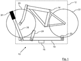
- the bicycle rack 10 is shown in Figure 1 from the rear and is in the form of apparatus 10 for connecting to a motor vehicle 12 and for carrying one or more bicycles 14.
- the apparatus 10 comprises a central frame 16 for connecting to a motor vehicle 12, a rail 18 connected to the central frame 16 and aligned perpendicular to the central frame 16, a rear wheel connector 20 connected to the rail 18 at one end thereof and for connecting to a rear wheel 22 of a bicycle 14, a front wheel stop 24 connected to the rail 18 for bracing against a front wheel 26 of a bicycle 14, and a front wheel connector 28 rotationally connected to the rail 18 at an opposite end of the rail 18 to the rear wheel connector 20 and for connecting to a front wheel 26 of a bicycle 14.
- the front wheel connector 28 mounts a front wheel clamp 32 on one end of the front wheel connector 28, where the front wheel connector 28 is rotationally connected to the respective rail 18 and 30 at the opposite end to the front wheel clamp 32.
- the front wheel clamp 32 comprises a hook 34 for looping over a front wheel 26 of a bicycle 14.
- the front wheel connector 28 is extendable in length and is lockable at a plurality of different lengths.
- the front wheel stop 24 is rotationally connected to the respective rail 18, 30.
- the bicycle 14 is held in place at one end by the rear wheel connector 20, which is a strap.
- the front wheel 26 of the bicycle 14 is held from any freedom of movement by the front wheel stop 24, the contact with the rail 18 and by the front wheel connector 28 that can be varied in length and is restricted from pivoting outwards.
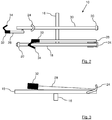
- FIG. 2 shows the bicycle rack 10 viewed from above.
- the bicycle rack 10 shown in this Figure is for carrying two bicycles 14 and is provided with a second rail 30.
- the second rail 30 connected to the central frame 16 and is aligned perpendicular to the central frame 16 and parallel and spaced apart from the first rail 18, and there is additionally a rear wheel connector 20 connected to the second rail 30 at one end thereof and for connecting to a rear wheel 22 of a bicycle 14, a front wheel stop 24 connected to the second rail 30 for bracing against a front wheel 26 of a bicycle 14, and a front wheel connector 28 rotationally connected to the second rail 30 at an opposite end of the second rail 30 to the rear wheel connector 20 and for connecting to a front wheel 26 of a bicycle 14.
- the second rail 30 is connected to the central frame 16 in an opposite orientation to the first rail 18, such that one end of the second rail 30 is adjacent to the opposite end of the first rail 18.
- This arrangement results in the bicycles 14 that are carried by the bicycle rack 10 being in opposite orientation to one another, to achieve the best use of space.
- the two bicycles 14 would face in opposite directions, while remaining parallel to one another.
- the handlebars of one bicycle 14 would be adjacent to the seat of the other bicycle 14, and vice versa.
- the inner rail 30 is shown in a condition ready to accept a bicycle 14 with the front wheel connector 28 rotated outwards and the front wheel stop 24 rotated inwards.
- the outer rail 18 is shown in its stored configuration, with the front wheel connector 28 and the front wheel stop 24 folded down to reduce the storage space required to store the bicycle rack 10. It is apparent that access to the vehicle's tailgate is maintained when the bicycle rack 10 is mounted on the vehicle 12, as the arms can be folded into a low and compact position.
- FIG 3 shows the bicycle rack 10 from the rear in its folded configuration. It can be seen from this Figure that the bicycle rack 10, when folded, is very flat and does not take up much room in the vertical direction.
- the outer rail 18 is visible, mounted by the central frame 16, such that each rail 18 and 30 is connected to the central frame 16 at a central location of the respective rail 18 and 30.
- the front wheel connector 28 of the outer rail 18 has been folded inwards such that it is almost parallel to the rail 18 and lies flat, with the hook 34 in contact with the rail 18.
- the front wheel stop 24 has been folded outwards again so that it is almost parallel to the rail 18 and lies flat against the rail 18.
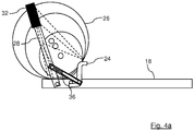
- Figure 4a shows the front wheel connector 28 with three sizes of bicycle front wheel 26 held securely in place.
- the front wheel connector 28 is restricted from rotating further outboard by a stop 36, or a cable, which connects the front wheel connector 28 to the front wheel stop 24.
- the front wheel stop 24 is restricted from rotating further inboard by contacting a protruding pin. It is apparent that many sizes of wheel 26 are accommodated and the long arm of the connector 28 is always forward of the axis of the front wheels 26 and in front of any mudguard and brake callipers. In order to secure the front wheel 26 it is necessary to hold the wheel 26 in three places such that a triangle is made by connecting the three points. The centre of the wheel 26 should always sit within this triangle.
- the front wheel stop 24 By fixing the front wheel stop 24 above and midpoint from the end of the rail 18 to the central frame 16, it is possible to provide two points of contact (the rail 18 and the stop 24).
- the third contact point at the top of the wheel 26 is defined by the front wheel clamp 32 at the top of the front wheel connector 28, which is restricted from rotating further outboard from the rail 18 and has a ratchet device which can exert pressure retaining the wheel 26 and therefore the bicycle 14.
- the front wheel connector 28 is pivoted from the far end of the rail 18 so that its trajectory is beyond the axis of the front wheel 26 and therefore does not need to be so far from the centreline of the wheel 26.
- the stop 36 comprises an elongate bar 36 which is connected at one end to the front wheel connector 28 and is connected at the opposite end to the front wheel stop 24.
- the elongate bar 36 is connected to the turning point of the front wheel stop.
- the elongate bar 36 is provided with an open slot in the middle and the connection to the front wheel connector 28 is via a wheel that locates in the slot.
- the purpose of the elongate bar 36 is to prevent rotation of the front wheel connector 28 beyond a specific point.
- the front wheel connector 28 is shown in its maximum rotational position, it cannot rotate any further anti-clockwise from the position shown in this Figure.
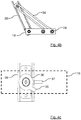
- Figure 4c shows a second embodiment of the stop 36.
- the stop 36 is a component 36 connected to the front wheel connector 28 and comprising an outwardly extending finger 35 which engages with an element 37 mounted on the rail.
- the finger 35 will engage with the element 37 and no further rotation of the front wheel connector 28 will be possible.
- Figure 5 illustrates the front wheel connector 28 from above which is shown as close to the centre line of a wheel 26 of a bicycle 14 such that moment forces are low and mass can be minimised.
- the central frame 16 includes a latching mechanism 38 at one end thereof, the latching mechanism 38 for locking the central frame 16 to a receiver 40 of the vehicle 12. At least part of the latching mechanism 38 is located internally within the central frame 16 and includes a moveable latch 42 that is biased to move and extend out of the central frame 16.
- Figure 6 shows the internal automatic latching system 38 such that the latch 42 is biased to be sprung outboard, but during loading of the accessory the spring 43 is compressed and the latch 42 rotates downwards.
- Figure 7 shows the bicycle rack 10 latched into position such that removal of the rack 10 is blocked by the engagement of the latch 42 into a hole on the receiver 40.
- a handle on the side of the frame 16 acting at the hinge point allows rotation of the latch 42 to compress the spring 43. It should be noted that a stop 45 is required to avoid the bicycle rack 10 moving further into the receiver 40 and unlatching.
- Figure 8 shows a further side view of the receiver 40.
- a small ledge protruding from the bottom lip of the receiver 40.
- This ledge provides a useful resting place for the bicycle rack 10 such that the fitting effort is reduced and the bicycle rack 10 can be more easily aligned to the receiver 40. Further the most significant loads are the vertical bending on the receiver 40 and the additional overhang at the bottom is advantageous in carrying these loads efficiently.
- Figure 9 shows the side view of a vehicle 12 with the bicycle rack 10 attached.
- the receiver 40 is located at an angle to the horizontal, such that the central frame 16 extends upwards and away from the vehicle 12 mounting the receiver 40.
- a departure angle for the vehicle 12 should be 11 to 16 degrees as measured from the rear tyre.
- the bicycle rack 10 is basically flat in design aiding storage space. By setting the angle of the receiver 40, it is possible to maintain a simple structure and flat rack even if bicycle rack 10 is extended further, such as a three, four or five bicycle rack.
- the central frame 16 in a preferred embodiment, comprises two frame components 16a and 16b connected together at respective ends thereof, where the first frame component 16a can be located internally within the second frame component 16b when the two frame components 16a and 16b are disconnected from each other.
- Figure 10 shows a side elevation of the bicycle rack 10 in this form. It is advantageous if the packaging requirement of the bicycle rack 10 is small when not in use. By providing a hole 46 in the second frame component 16b that is matched with a fixing hole 46 for the receiver 40 it is possible to secure the first frame component 16a to the second frame component 16b when storing.
- Figure 11 shows that the first frame component 16a can slide into the second frame component 16b and the total package size is significantly diminished. Further intermediate positions may be useful for those wishing to store an accessory on the vehicle 12, or for carrying a reduced number of bicycles 14, but without the significant overhang.
- Each frame component 16a and 16b can be provided with two pairs of lateral holes 46 therethrough and the bicycle rack 10 further comprises a locking pin 48 for connecting together the two frame components 16a and 16b through one pair of lateral holes 46 in each frame component 16a and 16b.
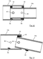
- the frame components 16a and 16b can be further provided with one or more lugs 50 and 52, the lugs 50 located internally within the second frame component 16b and the lugs 52 located externally on the first frame component 16a. This is shown in detail in Figures 12 and 13 .
- Figure 12 shows a side view detail of the joint between first and second frame components 16a and 16b. If the frame components 16a and 16b are unattached at the holes 46 then the frame components 16a and 16b can also be moved apart for the purposes of tilting the accessory away from the vehicle 12 as would be useful for access to the tailgate when bicycles 14 are already loaded.
- Figure 13 shows that the frame components 16a and 16b are restricted from being removed completely as the top bearing lug 52 of the first frame component 16a contacts the top bearing lug 50 of the second frame component 16b. However, due to the disengagement of lower bearing the first and second frame components 16a and 16b are free to rotate about an axis perpendicular to this view.
- a second pin hole may be provided with automatic plunging pin fitted to the second frame component 16b such that, in the case of driving off with the bicycle rack 10 left in a tilted condition, there is a secondary attachment which can secure the bicycle rack 10 to the vehicle 12 in the likelihood that the bearings will detach and the frame components 16a and 16b freely rotate relative to each other and the bicycle rack 10 contacts the road.
Landscapes
- Engineering & Computer Science (AREA)
- Mechanical Engineering (AREA)
- Fittings On The Vehicle Exterior For Carrying Loads, And Devices For Holding Or Mounting Articles (AREA)
Applications Claiming Priority (1)
| Application Number | Priority Date | Filing Date | Title |
|---|---|---|---|
| GB1703997.5A GB2560705A (en) | 2017-03-13 | 2017-03-13 | Bicycle Rack |
Publications (2)
| Publication Number | Publication Date |
|---|---|
| EP3375667A1 true EP3375667A1 (fr) | 2018-09-19 |
| EP3375667B1 EP3375667B1 (fr) | 2019-10-09 |
Family
ID=58605384
Family Applications (1)
| Application Number | Title | Priority Date | Filing Date |
|---|---|---|---|
| EP18161295.3A Active EP3375667B1 (fr) | 2017-03-13 | 2018-03-12 | Porte-vélo |
Country Status (2)
| Country | Link |
|---|---|
| EP (1) | EP3375667B1 (fr) |
| GB (1) | GB2560705A (fr) |
Citations (6)
| Publication number | Priority date | Publication date | Assignee | Title |
|---|---|---|---|---|
| US5570825A (en) * | 1995-05-22 | 1996-11-05 | Cona; John A. | Rear mount bicycle carrier rack for motor vehicles |
| US5833074A (en) * | 1995-04-06 | 1998-11-10 | Phillips; Cal M. | Fast-loading, protective bicycle rack |
| US20080164292A1 (en) * | 2006-06-29 | 2008-07-10 | Michael Kent Farney | Bicycle carrier |
| US20090236382A1 (en) * | 2007-07-06 | 2009-09-24 | Chris Sautter | Hitch mounted bicycle racks for vehicles |
| WO2010141944A1 (fr) * | 2009-06-05 | 2010-12-09 | Yakima Products, Inc. | Porte-vélo vertical |
| US20160068111A1 (en) * | 2014-09-05 | 2016-03-10 | Cequent Performance Products, Inc. | Bike carrier |
Family Cites Families (1)
| Publication number | Priority date | Publication date | Assignee | Title |
|---|---|---|---|---|
| US9073492B1 (en) * | 2014-01-13 | 2015-07-07 | Jason Shih Chieh Shen | Adjustable bicycle carrier |
-
2017
- 2017-03-13 GB GB1703997.5A patent/GB2560705A/en not_active Withdrawn
-
2018
- 2018-03-12 EP EP18161295.3A patent/EP3375667B1/fr active Active
Patent Citations (6)
| Publication number | Priority date | Publication date | Assignee | Title |
|---|---|---|---|---|
| US5833074A (en) * | 1995-04-06 | 1998-11-10 | Phillips; Cal M. | Fast-loading, protective bicycle rack |
| US5570825A (en) * | 1995-05-22 | 1996-11-05 | Cona; John A. | Rear mount bicycle carrier rack for motor vehicles |
| US20080164292A1 (en) * | 2006-06-29 | 2008-07-10 | Michael Kent Farney | Bicycle carrier |
| US20090236382A1 (en) * | 2007-07-06 | 2009-09-24 | Chris Sautter | Hitch mounted bicycle racks for vehicles |
| WO2010141944A1 (fr) * | 2009-06-05 | 2010-12-09 | Yakima Products, Inc. | Porte-vélo vertical |
| US20160068111A1 (en) * | 2014-09-05 | 2016-03-10 | Cequent Performance Products, Inc. | Bike carrier |
Also Published As
| Publication number | Publication date |
|---|---|
| EP3375667B1 (fr) | 2019-10-09 |
| GB2560705A (en) | 2018-09-26 |
| GB201703997D0 (en) | 2017-04-26 |
Similar Documents
| Publication | Publication Date | Title |
|---|---|---|
| US11351929B2 (en) | Hitch-mounted bicycle rack system | |
| US8235268B2 (en) | Pivoting hitch-mountable bicycle carrier | |
| US8496145B2 (en) | Vehicle rack for carrying a wheel | |
| US8113398B2 (en) | Hitch mounted bicycle racks for vehicles | |
| EP3428016B1 (fr) | Un support de bicyclette monté sur véhicule | |
| US6755599B1 (en) | Recessed wheel chock | |
| US20120000952A1 (en) | Bike rack | |
| US12397722B2 (en) | System for transporting child stroller | |
| US20080296330A1 (en) | Mountable storage arrangement | |
| US20200094750A1 (en) | Method and System for Carrying a Bicycle on a Vehicle | |
| US6481735B1 (en) | Apparatus for carrying a load behind a bicycle | |
| EP3375667B1 (fr) | Porte-vélo | |
| US20080047994A1 (en) | Holding system for transporting two wheeled vehicles | |
| CZ20002535A3 (cs) | Zařízení pro uložení a přepravu motocyklu | |
| US10106100B1 (en) | Secure latch for coupled assemblies | |
| CA3124549C (fr) | Porte-velo monte sur un vehicule | |
| US20220161733A1 (en) | Vehicle Mounted Bike Rack | |
| GB2255943A (en) | Carrier for fixing to a tow bar to a vehicle. | |
| WO2017156553A1 (fr) | Dispositif de chargement de motocyclette | |
| US20230227118A1 (en) | Vertical Bicycle Rack with Adjustable Tire Cradle | |
| EP3724034B1 (fr) | Dispositif permettant de transporter des bicyclettes sur des véhicules à moteur |
Legal Events
| Date | Code | Title | Description |
|---|---|---|---|
| PUAI | Public reference made under article 153(3) epc to a published international application that has entered the european phase |
Free format text: ORIGINAL CODE: 0009012 |
|
| STAA | Information on the status of an ep patent application or granted ep patent |
Free format text: STATUS: THE APPLICATION HAS BEEN PUBLISHED |
|
| AK | Designated contracting states |
Kind code of ref document: A1 Designated state(s): AL AT BE BG CH CY CZ DE DK EE ES FI FR GB GR HR HU IE IS IT LI LT LU LV MC MK MT NL NO PL PT RO RS SE SI SK SM TR |
|
| AX | Request for extension of the european patent |
Extension state: BA ME |
|
| STAA | Information on the status of an ep patent application or granted ep patent |
Free format text: STATUS: REQUEST FOR EXAMINATION WAS MADE |
|
| 17P | Request for examination filed |
Effective date: 20190319 |
|
| RBV | Designated contracting states (corrected) |
Designated state(s): AL AT BE BG CH CY CZ DE DK EE ES FI FR GB GR HR HU IE IS IT LI LT LU LV MC MK MT NL NO PL PT RO RS SE SI SK SM TR |
|
| GRAP | Despatch of communication of intention to grant a patent |
Free format text: ORIGINAL CODE: EPIDOSNIGR1 |
|
| RIC1 | Information provided on ipc code assigned before grant |
Ipc: B60R 9/10 20060101ALI20190522BHEP Ipc: B60R 9/06 20060101AFI20190522BHEP |
|
| INTG | Intention to grant announced |
Effective date: 20190617 |
|
| STAA | Information on the status of an ep patent application or granted ep patent |
Free format text: STATUS: GRANT OF PATENT IS INTENDED |
|
| GRAS | Grant fee paid |
Free format text: ORIGINAL CODE: EPIDOSNIGR3 |
|
| GRAA | (expected) grant |
Free format text: ORIGINAL CODE: 0009210 |
|
| STAA | Information on the status of an ep patent application or granted ep patent |
Free format text: STATUS: THE PATENT HAS BEEN GRANTED |
|
| AK | Designated contracting states |
Kind code of ref document: B1 Designated state(s): AL AT BE BG CH CY CZ DE DK EE ES FI FR GB GR HR HU IE IS IT LI LT LU LV MC MK MT NL NO PL PT RO RS SE SI SK SM TR |
|
| REG | Reference to a national code |
Ref country code: GB Ref legal event code: FG4D |
|
| REG | Reference to a national code |
Ref country code: CH Ref legal event code: EP |
|
| REG | Reference to a national code |
Ref country code: IE Ref legal event code: FG4D |
|
| REG | Reference to a national code |
Ref country code: DE Ref legal event code: R096 Ref document number: 602018000818 Country of ref document: DE |
|
| REG | Reference to a national code |
Ref country code: AT Ref legal event code: REF Ref document number: 1188422 Country of ref document: AT Kind code of ref document: T Effective date: 20191115 |
|
| REG | Reference to a national code |
Ref country code: NL Ref legal event code: MP Effective date: 20191009 |
|
| REG | Reference to a national code |
Ref country code: LT Ref legal event code: MG4D |
|
| REG | Reference to a national code |
Ref country code: AT Ref legal event code: MK05 Ref document number: 1188422 Country of ref document: AT Kind code of ref document: T Effective date: 20191009 |
|
| PG25 | Lapsed in a contracting state [announced via postgrant information from national office to epo] |
Ref country code: FI Free format text: LAPSE BECAUSE OF FAILURE TO SUBMIT A TRANSLATION OF THE DESCRIPTION OR TO PAY THE FEE WITHIN THE PRESCRIBED TIME-LIMIT Effective date: 20191009 Ref country code: BG Free format text: LAPSE BECAUSE OF FAILURE TO SUBMIT A TRANSLATION OF THE DESCRIPTION OR TO PAY THE FEE WITHIN THE PRESCRIBED TIME-LIMIT Effective date: 20200109 Ref country code: NO Free format text: LAPSE BECAUSE OF FAILURE TO SUBMIT A TRANSLATION OF THE DESCRIPTION OR TO PAY THE FEE WITHIN THE PRESCRIBED TIME-LIMIT Effective date: 20200109 Ref country code: LT Free format text: LAPSE BECAUSE OF FAILURE TO SUBMIT A TRANSLATION OF THE DESCRIPTION OR TO PAY THE FEE WITHIN THE PRESCRIBED TIME-LIMIT Effective date: 20191009 Ref country code: NL Free format text: LAPSE BECAUSE OF FAILURE TO SUBMIT A TRANSLATION OF THE DESCRIPTION OR TO PAY THE FEE WITHIN THE PRESCRIBED TIME-LIMIT Effective date: 20191009 Ref country code: AT Free format text: LAPSE BECAUSE OF FAILURE TO SUBMIT A TRANSLATION OF THE DESCRIPTION OR TO PAY THE FEE WITHIN THE PRESCRIBED TIME-LIMIT Effective date: 20191009 Ref country code: ES Free format text: LAPSE BECAUSE OF FAILURE TO SUBMIT A TRANSLATION OF THE DESCRIPTION OR TO PAY THE FEE WITHIN THE PRESCRIBED TIME-LIMIT Effective date: 20191009 Ref country code: PT Free format text: LAPSE BECAUSE OF FAILURE TO SUBMIT A TRANSLATION OF THE DESCRIPTION OR TO PAY THE FEE WITHIN THE PRESCRIBED TIME-LIMIT Effective date: 20200210 Ref country code: GR Free format text: LAPSE BECAUSE OF FAILURE TO SUBMIT A TRANSLATION OF THE DESCRIPTION OR TO PAY THE FEE WITHIN THE PRESCRIBED TIME-LIMIT Effective date: 20200110 Ref country code: PL Free format text: LAPSE BECAUSE OF FAILURE TO SUBMIT A TRANSLATION OF THE DESCRIPTION OR TO PAY THE FEE WITHIN THE PRESCRIBED TIME-LIMIT Effective date: 20191009 Ref country code: SE Free format text: LAPSE BECAUSE OF FAILURE TO SUBMIT A TRANSLATION OF THE DESCRIPTION OR TO PAY THE FEE WITHIN THE PRESCRIBED TIME-LIMIT Effective date: 20191009 Ref country code: LV Free format text: LAPSE BECAUSE OF FAILURE TO SUBMIT A TRANSLATION OF THE DESCRIPTION OR TO PAY THE FEE WITHIN THE PRESCRIBED TIME-LIMIT Effective date: 20191009 |
|
| PG25 | Lapsed in a contracting state [announced via postgrant information from national office to epo] |
Ref country code: IS Free format text: LAPSE BECAUSE OF FAILURE TO SUBMIT A TRANSLATION OF THE DESCRIPTION OR TO PAY THE FEE WITHIN THE PRESCRIBED TIME-LIMIT Effective date: 20200224 Ref country code: HR Free format text: LAPSE BECAUSE OF FAILURE TO SUBMIT A TRANSLATION OF THE DESCRIPTION OR TO PAY THE FEE WITHIN THE PRESCRIBED TIME-LIMIT Effective date: 20191009 Ref country code: RS Free format text: LAPSE BECAUSE OF FAILURE TO SUBMIT A TRANSLATION OF THE DESCRIPTION OR TO PAY THE FEE WITHIN THE PRESCRIBED TIME-LIMIT Effective date: 20191009 |
|
| PG25 | Lapsed in a contracting state [announced via postgrant information from national office to epo] |
Ref country code: AL Free format text: LAPSE BECAUSE OF FAILURE TO SUBMIT A TRANSLATION OF THE DESCRIPTION OR TO PAY THE FEE WITHIN THE PRESCRIBED TIME-LIMIT Effective date: 20191009 |
|
| REG | Reference to a national code |
Ref country code: DE Ref legal event code: R097 Ref document number: 602018000818 Country of ref document: DE |
|
| PG2D | Information on lapse in contracting state deleted |
Ref country code: IS |
|
| PG25 | Lapsed in a contracting state [announced via postgrant information from national office to epo] |
Ref country code: DK Free format text: LAPSE BECAUSE OF FAILURE TO SUBMIT A TRANSLATION OF THE DESCRIPTION OR TO PAY THE FEE WITHIN THE PRESCRIBED TIME-LIMIT Effective date: 20191009 Ref country code: RO Free format text: LAPSE BECAUSE OF FAILURE TO SUBMIT A TRANSLATION OF THE DESCRIPTION OR TO PAY THE FEE WITHIN THE PRESCRIBED TIME-LIMIT Effective date: 20191009 Ref country code: CZ Free format text: LAPSE BECAUSE OF FAILURE TO SUBMIT A TRANSLATION OF THE DESCRIPTION OR TO PAY THE FEE WITHIN THE PRESCRIBED TIME-LIMIT Effective date: 20191009 Ref country code: EE Free format text: LAPSE BECAUSE OF FAILURE TO SUBMIT A TRANSLATION OF THE DESCRIPTION OR TO PAY THE FEE WITHIN THE PRESCRIBED TIME-LIMIT Effective date: 20191009 Ref country code: IS Free format text: LAPSE BECAUSE OF FAILURE TO SUBMIT A TRANSLATION OF THE DESCRIPTION OR TO PAY THE FEE WITHIN THE PRESCRIBED TIME-LIMIT Effective date: 20200209 |
|
| PLBE | No opposition filed within time limit |
Free format text: ORIGINAL CODE: 0009261 |
|
| STAA | Information on the status of an ep patent application or granted ep patent |
Free format text: STATUS: NO OPPOSITION FILED WITHIN TIME LIMIT |
|
| PG25 | Lapsed in a contracting state [announced via postgrant information from national office to epo] |
Ref country code: SK Free format text: LAPSE BECAUSE OF FAILURE TO SUBMIT A TRANSLATION OF THE DESCRIPTION OR TO PAY THE FEE WITHIN THE PRESCRIBED TIME-LIMIT Effective date: 20191009 Ref country code: IT Free format text: LAPSE BECAUSE OF FAILURE TO SUBMIT A TRANSLATION OF THE DESCRIPTION OR TO PAY THE FEE WITHIN THE PRESCRIBED TIME-LIMIT Effective date: 20191009 Ref country code: SM Free format text: LAPSE BECAUSE OF FAILURE TO SUBMIT A TRANSLATION OF THE DESCRIPTION OR TO PAY THE FEE WITHIN THE PRESCRIBED TIME-LIMIT Effective date: 20191009 |
|
| 26N | No opposition filed |
Effective date: 20200710 |
|
| REG | Reference to a national code |
Ref country code: DE Ref legal event code: R119 Ref document number: 602018000818 Country of ref document: DE |
|
| PG25 | Lapsed in a contracting state [announced via postgrant information from national office to epo] |
Ref country code: MC Free format text: LAPSE BECAUSE OF FAILURE TO SUBMIT A TRANSLATION OF THE DESCRIPTION OR TO PAY THE FEE WITHIN THE PRESCRIBED TIME-LIMIT Effective date: 20191009 |
|
| PG25 | Lapsed in a contracting state [announced via postgrant information from national office to epo] |
Ref country code: SI Free format text: LAPSE BECAUSE OF FAILURE TO SUBMIT A TRANSLATION OF THE DESCRIPTION OR TO PAY THE FEE WITHIN THE PRESCRIBED TIME-LIMIT Effective date: 20191009 |
|
| REG | Reference to a national code |
Ref country code: BE Ref legal event code: MM Effective date: 20200331 |
|
| PG25 | Lapsed in a contracting state [announced via postgrant information from national office to epo] |
Ref country code: LU Free format text: LAPSE BECAUSE OF NON-PAYMENT OF DUE FEES Effective date: 20200312 |
|
| PG25 | Lapsed in a contracting state [announced via postgrant information from national office to epo] |
Ref country code: DE Free format text: LAPSE BECAUSE OF NON-PAYMENT OF DUE FEES Effective date: 20201001 Ref country code: IE Free format text: LAPSE BECAUSE OF NON-PAYMENT OF DUE FEES Effective date: 20200312 |
|
| PG25 | Lapsed in a contracting state [announced via postgrant information from national office to epo] |
Ref country code: BE Free format text: LAPSE BECAUSE OF NON-PAYMENT OF DUE FEES Effective date: 20200331 |
|
| REG | Reference to a national code |
Ref country code: DE Ref legal event code: R073 Ref document number: 602018000818 Country of ref document: DE |
|
| REG | Reference to a national code |
Ref country code: DE Ref legal event code: R074 Ref document number: 602018000818 Country of ref document: DE |
|
| PG25 | Lapsed in a contracting state [announced via postgrant information from national office to epo] |
Ref country code: DE Free format text: LAPSE BECAUSE OF NON-PAYMENT OF DUE FEES Effective date: 20201001 |
|
| PGRI | Patent reinstated in contracting state [announced from national office to epo] |
Ref country code: DE Effective date: 20210611 |
|
| REG | Reference to a national code |
Ref country code: CH Ref legal event code: PL |
|
| PG25 | Lapsed in a contracting state [announced via postgrant information from national office to epo] |
Ref country code: CH Free format text: LAPSE BECAUSE OF NON-PAYMENT OF DUE FEES Effective date: 20210331 Ref country code: LI Free format text: LAPSE BECAUSE OF NON-PAYMENT OF DUE FEES Effective date: 20210331 |
|
| PG25 | Lapsed in a contracting state [announced via postgrant information from national office to epo] |
Ref country code: TR Free format text: LAPSE BECAUSE OF FAILURE TO SUBMIT A TRANSLATION OF THE DESCRIPTION OR TO PAY THE FEE WITHIN THE PRESCRIBED TIME-LIMIT Effective date: 20191009 Ref country code: MT Free format text: LAPSE BECAUSE OF FAILURE TO SUBMIT A TRANSLATION OF THE DESCRIPTION OR TO PAY THE FEE WITHIN THE PRESCRIBED TIME-LIMIT Effective date: 20191009 Ref country code: CY Free format text: LAPSE BECAUSE OF FAILURE TO SUBMIT A TRANSLATION OF THE DESCRIPTION OR TO PAY THE FEE WITHIN THE PRESCRIBED TIME-LIMIT Effective date: 20191009 |
|
| PG25 | Lapsed in a contracting state [announced via postgrant information from national office to epo] |
Ref country code: MK Free format text: LAPSE BECAUSE OF FAILURE TO SUBMIT A TRANSLATION OF THE DESCRIPTION OR TO PAY THE FEE WITHIN THE PRESCRIBED TIME-LIMIT Effective date: 20191009 |
|
| GRAP | Despatch of communication of intention to grant a patent |
Free format text: ORIGINAL CODE: EPIDOSNIGR1 |
|
| PGFP | Annual fee paid to national office [announced via postgrant information from national office to epo] |
Ref country code: GB Payment date: 20260227 Year of fee payment: 9 |
|
| PGFP | Annual fee paid to national office [announced via postgrant information from national office to epo] |
Ref country code: DE Payment date: 20260316 Year of fee payment: 9 |
|
| PGFP | Annual fee paid to national office [announced via postgrant information from national office to epo] |
Ref country code: FR Payment date: 20260319 Year of fee payment: 9 |