EP3375679A1 - Brems-/antriebskraftsteuerungsverfahren und brems-/antriebskraftsteuerungsvorrichtung - Google Patents
Brems-/antriebskraftsteuerungsverfahren und brems-/antriebskraftsteuerungsvorrichtung Download PDFInfo
- Publication number
- EP3375679A1 EP3375679A1 EP15908237.9A EP15908237A EP3375679A1 EP 3375679 A1 EP3375679 A1 EP 3375679A1 EP 15908237 A EP15908237 A EP 15908237A EP 3375679 A1 EP3375679 A1 EP 3375679A1
- Authority
- EP
- European Patent Office
- Prior art keywords
- braking
- driving force
- driving
- accelerator pedal
- braking force
- Prior art date
- Legal status (The legal status is an assumption and is not a legal conclusion. Google has not performed a legal analysis and makes no representation as to the accuracy of the status listed.)
- Granted
Links
Images










Classifications
-
- B—PERFORMING OPERATIONS; TRANSPORTING
- B60—VEHICLES IN GENERAL
- B60W—CONJOINT CONTROL OF VEHICLE SUB-UNITS OF DIFFERENT TYPE OR DIFFERENT FUNCTION; CONTROL SYSTEMS SPECIALLY ADAPTED FOR HYBRID VEHICLES; ROAD VEHICLE DRIVE CONTROL SYSTEMS FOR PURPOSES NOT RELATED TO THE CONTROL OF A PARTICULAR SUB-UNIT
- B60W30/00—Purposes of road vehicle drive control systems not related to the control of a particular sub-unit, e.g. of systems using conjoint control of vehicle sub-units
- B60W30/14—Adaptive cruise control
-
- B—PERFORMING OPERATIONS; TRANSPORTING
- B60—VEHICLES IN GENERAL
- B60W—CONJOINT CONTROL OF VEHICLE SUB-UNITS OF DIFFERENT TYPE OR DIFFERENT FUNCTION; CONTROL SYSTEMS SPECIALLY ADAPTED FOR HYBRID VEHICLES; ROAD VEHICLE DRIVE CONTROL SYSTEMS FOR PURPOSES NOT RELATED TO THE CONTROL OF A PARTICULAR SUB-UNIT
- B60W30/00—Purposes of road vehicle drive control systems not related to the control of a particular sub-unit, e.g. of systems using conjoint control of vehicle sub-units
- B60W30/14—Adaptive cruise control
- B60W30/143—Speed control
-
- B—PERFORMING OPERATIONS; TRANSPORTING
- B60—VEHICLES IN GENERAL
- B60K—ARRANGEMENT OR MOUNTING OF PROPULSION UNITS OR OF TRANSMISSIONS IN VEHICLES; ARRANGEMENT OR MOUNTING OF PLURAL DIVERSE PRIME-MOVERS IN VEHICLES; AUXILIARY DRIVES FOR VEHICLES; INSTRUMENTATION OR DASHBOARDS FOR VEHICLES; ARRANGEMENTS IN CONNECTION WITH COOLING, AIR INTAKE, GAS EXHAUST OR FUEL SUPPLY OF PROPULSION UNITS IN VEHICLES
- B60K26/00—Arrangement or mounting of propulsion-unit control devices in vehicles
- B60K26/02—Arrangement or mounting of propulsion-unit control devices in vehicles of initiating means or elements
- B60K26/021—Arrangement or mounting of propulsion-unit control devices in vehicles of initiating means or elements with means for providing feel, e.g. by changing pedal force characteristics
-
- B—PERFORMING OPERATIONS; TRANSPORTING
- B60—VEHICLES IN GENERAL
- B60K—ARRANGEMENT OR MOUNTING OF PROPULSION UNITS OR OF TRANSMISSIONS IN VEHICLES; ARRANGEMENT OR MOUNTING OF PLURAL DIVERSE PRIME-MOVERS IN VEHICLES; AUXILIARY DRIVES FOR VEHICLES; INSTRUMENTATION OR DASHBOARDS FOR VEHICLES; ARRANGEMENTS IN CONNECTION WITH COOLING, AIR INTAKE, GAS EXHAUST OR FUEL SUPPLY OF PROPULSION UNITS IN VEHICLES
- B60K31/00—Vehicle fittings, acting on a single sub-unit only, for automatically controlling vehicle speed, i.e. preventing speed from exceeding an arbitrarily established velocity or maintaining speed at a particular velocity, as selected by the vehicle operator
-
- B—PERFORMING OPERATIONS; TRANSPORTING
- B60—VEHICLES IN GENERAL
- B60W—CONJOINT CONTROL OF VEHICLE SUB-UNITS OF DIFFERENT TYPE OR DIFFERENT FUNCTION; CONTROL SYSTEMS SPECIALLY ADAPTED FOR HYBRID VEHICLES; ROAD VEHICLE DRIVE CONTROL SYSTEMS FOR PURPOSES NOT RELATED TO THE CONTROL OF A PARTICULAR SUB-UNIT
- B60W10/00—Conjoint control of vehicle sub-units of different type or different function
- B60W10/04—Conjoint control of vehicle sub-units of different type or different function including control of propulsion units
-
- B—PERFORMING OPERATIONS; TRANSPORTING
- B60—VEHICLES IN GENERAL
- B60W—CONJOINT CONTROL OF VEHICLE SUB-UNITS OF DIFFERENT TYPE OR DIFFERENT FUNCTION; CONTROL SYSTEMS SPECIALLY ADAPTED FOR HYBRID VEHICLES; ROAD VEHICLE DRIVE CONTROL SYSTEMS FOR PURPOSES NOT RELATED TO THE CONTROL OF A PARTICULAR SUB-UNIT
- B60W10/00—Conjoint control of vehicle sub-units of different type or different function
- B60W10/18—Conjoint control of vehicle sub-units of different type or different function including control of braking systems
-
- B—PERFORMING OPERATIONS; TRANSPORTING
- B60—VEHICLES IN GENERAL
- B60W—CONJOINT CONTROL OF VEHICLE SUB-UNITS OF DIFFERENT TYPE OR DIFFERENT FUNCTION; CONTROL SYSTEMS SPECIALLY ADAPTED FOR HYBRID VEHICLES; ROAD VEHICLE DRIVE CONTROL SYSTEMS FOR PURPOSES NOT RELATED TO THE CONTROL OF A PARTICULAR SUB-UNIT
- B60W40/00—Estimation or calculation of non-directly measurable driving parameters for road vehicle drive control systems not related to the control of a particular sub unit, e.g. by using mathematical models
- B60W40/10—Estimation or calculation of non-directly measurable driving parameters for road vehicle drive control systems not related to the control of a particular sub unit, e.g. by using mathematical models related to vehicle motion
- B60W40/105—Speed
-
- B—PERFORMING OPERATIONS; TRANSPORTING
- B60—VEHICLES IN GENERAL
- B60W—CONJOINT CONTROL OF VEHICLE SUB-UNITS OF DIFFERENT TYPE OR DIFFERENT FUNCTION; CONTROL SYSTEMS SPECIALLY ADAPTED FOR HYBRID VEHICLES; ROAD VEHICLE DRIVE CONTROL SYSTEMS FOR PURPOSES NOT RELATED TO THE CONTROL OF A PARTICULAR SUB-UNIT
- B60W50/00—Details of control systems for road vehicle drive control not related to the control of a particular sub-unit, e.g. process diagnostic or vehicle driver interfaces
- B60W50/08—Interaction between the driver and the control system
- B60W50/10—Interpretation of driver requests or demands
-
- B—PERFORMING OPERATIONS; TRANSPORTING
- B60—VEHICLES IN GENERAL
- B60K—ARRANGEMENT OR MOUNTING OF PROPULSION UNITS OR OF TRANSMISSIONS IN VEHICLES; ARRANGEMENT OR MOUNTING OF PLURAL DIVERSE PRIME-MOVERS IN VEHICLES; AUXILIARY DRIVES FOR VEHICLES; INSTRUMENTATION OR DASHBOARDS FOR VEHICLES; ARRANGEMENTS IN CONNECTION WITH COOLING, AIR INTAKE, GAS EXHAUST OR FUEL SUPPLY OF PROPULSION UNITS IN VEHICLES
- B60K2310/00—Arrangements, adaptations or methods for cruise controls
- B60K2310/24—Speed setting methods
- B60K2310/248—Speed setting methods resuming speed control, e.g. returning to old target speed
-
- B—PERFORMING OPERATIONS; TRANSPORTING
- B60—VEHICLES IN GENERAL
- B60W—CONJOINT CONTROL OF VEHICLE SUB-UNITS OF DIFFERENT TYPE OR DIFFERENT FUNCTION; CONTROL SYSTEMS SPECIALLY ADAPTED FOR HYBRID VEHICLES; ROAD VEHICLE DRIVE CONTROL SYSTEMS FOR PURPOSES NOT RELATED TO THE CONTROL OF A PARTICULAR SUB-UNIT
- B60W2510/00—Input parameters relating to a particular sub-units
- B60W2510/06—Combustion engines, Gas turbines
- B60W2510/0657—Engine torque
-
- B—PERFORMING OPERATIONS; TRANSPORTING
- B60—VEHICLES IN GENERAL
- B60W—CONJOINT CONTROL OF VEHICLE SUB-UNITS OF DIFFERENT TYPE OR DIFFERENT FUNCTION; CONTROL SYSTEMS SPECIALLY ADAPTED FOR HYBRID VEHICLES; ROAD VEHICLE DRIVE CONTROL SYSTEMS FOR PURPOSES NOT RELATED TO THE CONTROL OF A PARTICULAR SUB-UNIT
- B60W2520/00—Input parameters relating to overall vehicle dynamics
- B60W2520/10—Longitudinal speed
-
- B—PERFORMING OPERATIONS; TRANSPORTING
- B60—VEHICLES IN GENERAL
- B60W—CONJOINT CONTROL OF VEHICLE SUB-UNITS OF DIFFERENT TYPE OR DIFFERENT FUNCTION; CONTROL SYSTEMS SPECIALLY ADAPTED FOR HYBRID VEHICLES; ROAD VEHICLE DRIVE CONTROL SYSTEMS FOR PURPOSES NOT RELATED TO THE CONTROL OF A PARTICULAR SUB-UNIT
- B60W2540/00—Input parameters relating to occupants
- B60W2540/10—Accelerator pedal position
-
- B—PERFORMING OPERATIONS; TRANSPORTING
- B60—VEHICLES IN GENERAL
- B60W—CONJOINT CONTROL OF VEHICLE SUB-UNITS OF DIFFERENT TYPE OR DIFFERENT FUNCTION; CONTROL SYSTEMS SPECIALLY ADAPTED FOR HYBRID VEHICLES; ROAD VEHICLE DRIVE CONTROL SYSTEMS FOR PURPOSES NOT RELATED TO THE CONTROL OF A PARTICULAR SUB-UNIT
- B60W2540/00—Input parameters relating to occupants
- B60W2540/10—Accelerator pedal position
- B60W2540/103—Accelerator thresholds, e.g. kickdown
-
- B—PERFORMING OPERATIONS; TRANSPORTING
- B60—VEHICLES IN GENERAL
- B60W—CONJOINT CONTROL OF VEHICLE SUB-UNITS OF DIFFERENT TYPE OR DIFFERENT FUNCTION; CONTROL SYSTEMS SPECIALLY ADAPTED FOR HYBRID VEHICLES; ROAD VEHICLE DRIVE CONTROL SYSTEMS FOR PURPOSES NOT RELATED TO THE CONTROL OF A PARTICULAR SUB-UNIT
- B60W2720/00—Output or target parameters relating to overall vehicle dynamics
- B60W2720/10—Longitudinal speed
Definitions
- This invention relates to a braking/driving force control method and a braking/driving force control device.
- PTL 1 discloses, for example a technology for controlling a braking/driving force of a vehicle.
- An object of the present invention is to solve the above described problems and to provide a braking/driving force control method and a braking/driving force control device that suppress the discomfort given to the driver.
- the acceleration/deceleration of the vehicle is controlled in response to the target braking/driving torque. Further, when the driver demand torque exceeds the target braking/driving torque, the acceleration/deceleration is controlled depending on the driver demand torque.
- the driver demand torque is reduced depending on the decrease in the operation amount of the accelerator pedal.
- a decrease rate of the driver demand torque depending on the decrease in the operation amount of the accelerator pedal is set to be smaller than the decrease rate of the driver demand torque depending on the operation amount of the accelerator pedal for a case where the driver does not set the travelling speed.
- the acceleration/deceleration is controlled based on the set driver demand torque, and then, when the operation amount of the accelerator pedal becomes zero subsequently, the process returns to a state where the acceleration/deceleration is controlled based on the target braking/driving torque.
- the driver demand torque is decreased depending on the decrease in the operation amount of the accelerator pedal.
- the decrease rate of the driver demand torque depending on the decrease in the operation amount of the accelerator pedal is set to be smaller than the decrease rate of the driver demand torque depending on the operation amount of the accelerator pedal for a case where the driver does not set the travelling speed.
- the braking/driving force control device 1 includes an ITS control unit 2, a motor control unit 4, and a friction braking force control unit 6.
- the ITS control unit 2 is configured from, for example, a microcomputer.
- microcomputer includes, for example, Central Processing Unit (CPU), Random Access Memory (RAM), Read Only Memory (ROM) and the like.
- the ITS control unit 2 receives information signals from an external environment recognition sensor 8, a speed setting switch 10, a mode selection switch 12, a vehicle speed calculation unit 14, an accelerator sensor APS, and the motor control unit 4.
- the ITS control unit 2 uses various received information signals, controls a braking force and a driving force generated to a vehicle C including the braking/driving force control device 1.
- the braking force controlled by the ITS control unit 2 is the braking force that is controlled separately from a braking force request by a driver of a vehicle C.
- the driving force controlled by the ITS control unit 2 is the driving force that is controlled separately from the driving force request by a driver of the vehicle C.
- the external environment recognition sensor 8 is formed from, for example, an image capturing device such as a wide-angle camera and a distance measuring device such as a laser range finder (LRF).
- an image capturing device such as a wide-angle camera
- a distance measuring device such as a laser range finder (LRF).
- the external environment recognition sensor 8 using the image capturing device and the distance measuring device, detects a control object that is present at the circumference of the vehicle C (especially, in front of vehicle C).
- the external environment recognition sensor 8 that has detected the control object present at the circumference of the vehicle C outputs the information signal including the detected control object (hereinafter, sometimes referred to as "control object signal") to the ITS control unit 2.
- control objects are, for example, other vehicles such as preceding vehicles, pedestrians, animals, guard rails, curbstones, and a lane marking.
- the speed setting switch 10 is a switch for setting the travelling speed (control speed) of the vehicle C when the constant speed traveling control is conducted. Further, the speed setting switch 10 is formed from a switch (lever, button or the like) disposed at a position (such as steering wheel) where an occupant of the vehicle C (driver or the like) can operate the switch.
- the speed setting switch 10 outputs an information signal including the set travelling speed (set speed) (hereinafter sometimes referred to as "set speed signal") to the ITS control unit 2.
- the constant speed traveling control includes an automatic speed control (control for travelling vehicle C at a set travelling speed without pedaling accelerator pedal by driver) and controlling of a braking force or a driving force depending on the control object.
- whether or not to conduct the constant speed traveling control is selected by operating the switch (constant speed traveling control setting switch) disposed at a position (such as a steering wheel) where the occupant of the vehicle C can operate the switch.
- the mode selection switch 12 is a switch for selecting either one of a "one pedal mode” or a "two pedal mode” as a mode (control mode) for controlling the braking force and the driving force of the vehicle C.
- the "one pedal mode” is a control mode for controlling the braking force and the driving force of the vehicle C depending mainly on the operation of the accelerator pedal AP.
- the braking range is a range corresponding to the operation amount of the accelerator pedal AP from an unoperated state to a braking/driving force switching operation amount.
- the braking/driving force switching operation amount corresponds to, among the operation amounts (opening degree) of the accelerator pedal AP, the operation amount (opening degree) for switching between the driving force and the braking force generated to the vehicle C. Note that the braking/driving force switching operation amount is set to the operation amount (opening degree) of the accelerator pedal AP of about 25%.
- the driving force is generated to be increased depending on the increased amount of the operation amount of the accelerator pedal AP over the braking/driving force switching operation amount.
- the driving range is a range corresponding to the operation amount exceeding the braking/driving force switching operation amount of the accelerator pedal AP.
- the creep phenomenon is a phenomenon caused to an automatic transmission (AT) vehicle that includes an internal-combustion engine as a drive source.
- the braking/driving force control device 1 when the operation amount of the accelerator pedal AP is less than a threshold value set in advance, the braking/driving force control device 1 according to the first embodiment generates the braking force depending on the operation amount of the accelerator pedal AP that is less than the threshold value and the travelling speed of the vehicle C.
- the braking/driving force control device 1 when the operation amount of the accelerator pedal AP is equal to or larger than the threshold value, the braking/driving force control device 1 according to the first embodiment generates the driving force depending on the operation amount of the accelerator pedal AP that is equal to or larger than the threshold value and the travelling speed of the vehicle C.
- the "two pedal mode” is a control mode in which the braking force of the vehicle C is controlled in accordance with the operation of mainly a brake pedal BP and the driving force of the vehicle C is controlled in accordance with the operation of the accelerator pedal AP.
- the driving force is generated. Further, as the operation amount of the accelerator pedal AP increases, the driving force increases.
- a braking force corresponding to the engine brake is caused, which braking force is generally caused to a vehicle having an internal-combustion engine as a drive source.
- a control for not causing the braking force corresponding to the engine brake may be conducted.
- the mode selection switch 12 is formed from a switch (dial or the like) disposed at a position (such as a dash board) where the occupant of the vehicle C can operate the switch.
- the mode selection switch 12 outputs an information signal including a selection result of a control mode (hereinafter sometimes referred to as "select mode signal") to the ITS control unit 2 and the motor control unit 4.
- the vehicle speed calculation unit 14 receives, from a wheel speed sensor 16, a wheel speed signal including a revolution speed of a wheel.
- the vehicle speed calculation unit 14 uses the revolution speed included in the wheel speed signal, calculates the travelling speed of the vehicle C (hereinafter sometimes referred to as "vehicle speed"). Additionally, the vehicle speed calculation unit 14 outputs an information signal including the calculated vehicle speed (hereinafter sometimes referred to as "vehicle speed signal") to the ITS control unit 2, the motor control unit 4, and the friction braking force control unit 6.
- vehicle speed calculation unit 14 may be included in, for example, a known Vehicle Dynamics Control (VDC) system.
- VDC Vehicle Dynamics Control
- the wheel speed sensor 16 is, as illustrated in FIG. 2 , mounted to the vehicle C.
- the wheel speed sensor 16 generates the predetermined number of wheel speed pulses for one rotation of the wheel W of the vehicle C.
- the wheel speed sensor 16 outputs the wheel speed signal including the revolution speed of the wheel to the motor control unit 4.
- the accelerator sensor APS is a sensor for detecting the operation amount (pedaling operation amount) of the accelerator pedal AP by the driver.
- the accelerator pedal AP is a pedal provided to the vehicle C and a pedal pedaled by the driver of the vehicle C in response to the braking force request or the driving force request.
- the accelerator sensor APS is formed by using, for example, a pedal stroke sensor. Further, a configuration of the accelerator sensor APS is not limited to be formed using the pedal stroke sensor, but may be a configuration in which, for example, the opening degree of the accelerator pedal AP by the pedaling operation of the driver is detected.
- the accelerator sensor APS is a sensor for detecting the operation amount of the accelerator pedal AP by the driver.
- the motor control unit 4 controls the regenerative braking force and the driving force generated to the vehicle C. Further, the motor control unit 4, similarly to the ITS control unit 2, is configured from, for example, a microcomputer.
- the motor control unit 4 receives information signals from the ITS control unit 2, the mode selection switch 12, the vehicle speed calculation unit 14, the wheel speed sensor 16, the accelerator sensor APS, a motor rotation speed sensor MS, and the friction braking force control unit 6.
- the motor rotation speed sensor MS is formed from, for example, a resolver that detects the rotation speed (rotation state) of a motor driving force output shaft of the driving motor DM.
- the motor rotation speed sensor MS in response to an output shaft pulse signal, detects the rotation speed (rotation state) of the motor driving force output shaft. Then, the motor rotation speed sensor MS outputs an output shaft rotation speed signal including the detected rotation speed to the motor control unit 4.
- the output shaft pulse signal is a pulse signal representing a rotation state of the motor driving force output shaft.
- the friction braking force control unit 6 controls a friction braking force generated to the vehicle C.
- the friction braking force control unit 6, similarly to the motor control unit 4, is configured from, for example, a microcomputer.
- the friction braking force control unit 6 receives information signals from the motor control unit 4, the vehicle speed calculation unit 14, and a brake sensor BPS.
- the brake sensor BPS is a sensor for detecting the operation amount (pedaling operation amount) of a brake pedal BP by the driver.
- the brake pedal BP is a pedal provided to the vehicle C, is a pedal pedaled by the driver of the vehicle C only in response to the braking force request, and is a pedal that is provided separately from the accelerator pedal AP.
- the brake sensor BPS outputs an information signal including the operation amount of the brake pedal BP by the driver to the friction braking force control unit 6.
- the brake sensor BPS is formed by using, for example, a pedal stroke sensor.
- a configuration of the brake sensor BPS is not limited to be formed using the pedal stroke sensor, but may be a configuration in which the opening degree of the brake pedal BP by the pedaling operation of the driver is detected.
- the brake sensor BPS is a sensor that detects the operation amount of the brake pedal BP by the driver.
- the ITS control unit 2 includes the ITS braking/driving force calculation unit 20, a driver request braking/driving force detection unit 22, a filter correction unit 24, and an ITS output setting unit 26.
- the ITS braking/driving force calculation unit 20 receives the set speed signal, the select mode signal, the vehicle speed signal, and the control object signal. Additionally, the ITS braking/driving force calculation unit 20 receives, from the accelerator sensor APS, an information signal including the operation amount (braking/driving force operation amount) of the accelerator pedal AP.
- the ITS braking/driving force calculation unit 20 calculates the driving force or the braking force generated to the vehicle C depending on the control mode included in the select mode signal and a deviation (speed difference) between the set speed included in the set speed signal and the vehicle speed included in the vehicle speed signal.
- the ITS braking/driving force calculation unit 20 increases the driving force (decreases braking force).
- the ITS braking/driving force calculation unit 20 decreases the driving force (increases braking force).
- the ITS braking/driving force calculation unit 20 based on the control object included in the control object signal, corrects the driving force or the braking force that is calculated depending on the speed difference between the set speed included in the set speed signal and the vehicle speed included in the vehicle speed signal.
- the correction of the driving force or the braking force conducted by the ITS braking/driving force calculation unit 20 is the correction of increasing the braking force when, for example, the control object is present in a travelling direction of the vehicle C and as the distance between the control object and the vehicle C is shorter. Further, the correction of the driving force or the braking force conducted by the ITS braking/driving force calculation unit 20 is the correction of increasing the driving force when, for example, the control object is present in the traveling direction of the vehicle C and as the distance between the control object and the vehicle C is shorter.
- the ITS braking/driving force calculation unit 20 that calculates the braking force or the driving force generated to the vehicle C outputs an information signal including the calculated braking force or driving force (hereinafter sometimes referred to as "ITS braking/driving force signal") to the ITS output setting unit 26.
- the driver request braking/driving force detection unit 22 receives, from the motor control unit 4, a corrected driving force signal or a corrected braking force signal.
- the corrected driving force signal is an information signal including a corrected driving force obtained by correcting, based on a direction and a magnitude of a road surface slope (slope of traveling road surface), the driving force depending on the operation amount of the accelerator pedal AP and the travelling speed of the vehicle C.
- the corrected braking force signal is an information signal including the corrected braking force obtained by correcting, based on a direction and a magnitude of a road surface slope, the braking force depending on the operation amount of the accelerator pedal AP and the travelling speed of the vehicle C.
- the driver request braking/driving force detection unit 22 that has received the corrected driving force signal, based on the driving force included in the corrected driving force signal, detects the driving force (driver request driving force) that seems to be requested by the driver of the vehicle C.
- the driver request braking/driving force detection unit 22 that has received the corrected braking force signal, based on the braking force included in the corrected braking force signal, detects the braking force (driver request braking force) that seems to be requested by the driver of the vehicle C.
- the driver request braking/driving force detection unit 22 that has detected the driver request driving force outputs an information signal including the detected driver request driving force (hereinafter sometimes referred to as "driver request driving force signal") to the ITS output setting unit 26.
- the driver request braking/driving force detection unit 22 that has detected the driver request braking force outputs an information signal including the detected driver request braking force (hereinafter sometimes referred to as "driver request braking force signal") to the ITS output setting unit 26.
- the filter correction unit 24 receives a set speed signal, a vehicle speed signal, and a Dr override determination signal.
- the Dr override determination signal is an information signal including a determination result as to whether or not a driver override is established.
- the driver override indicates a state in which the driver of the vehicle C has a control right of the driving force or the braking force of the vehicle C.
- the filter correction unit 24 uses various parameters included in the received information signal, corrects a filter (the ITS braking/driving force filter) used for processes of the ITS output setting unit 26.
- the filter correction unit 24 that has corrected ITS braking/driving force filter outputs an information signal including the corrected ITS braking/driving force filter (corrected filter) (hereinafter sometimes referred to as "corrected filter signal”) to the ITS output setting unit 26.
- corrected filter corrected filter
- the ITS output setting unit 26 receives the ITS braking/driving force signal, the driver request driving force signal or the driver request braking force signal, the corrected filter signal, and the Dr override determination signal.
- the ITS output setting unit 26 selects any one of the braking force or the driving force included in the ITS braking/driving force signal, the driver request driving force included in the driver request driving force signal, and the driver request braking force included in the driver request braking force signal.
- the ITS output setting unit 26 corrects any one selected among the braking force, the driving force, the driver request driving force, and the driver request braking force through the corrected filter included in the corrected filter signal to calculate a corrected ITS braking/driving force.
- the ITS output setting unit 26 that has calculated the corrected ITS braking/driving force outputs an information signal including the corrected ITS braking/driving force (hereinafter sometimes referred to as "corrected ITS output signal") to the motor control unit 4.
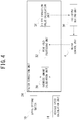
- the filter correction unit 24 includes, as illustrated in FIG. 4 , an override amount calculation unit 30, a peak hold processing unit 32, and a filter correction value calculation unit 34.
- the override amount calculation unit 30 receives the set speed signal and the vehicle speed signal.
- the override amount calculation unit 30 stores in advance an override amount calculation map.
- the override amount calculation map is, as illustrated in FIG. 5 , a map indicating a relationship between a deviation amount and an override amount. Further, the override amount calculation map is, as illustrated in FIG. 5 , a map set in advance such that when the deviation amount is a minimum deviation amount set in advance, the override amount becomes a minimum override value set in advance.
- the deviation amount is a value (speed difference) obtained by subtracting, from the vehicle speed included in the vehicle speed signal (current travelling speed of vehicle C), the set speed included in the set speed signal.
- the deviation amount is an amount by which the travelling speed calculated (detected) by the vehicle speed calculation unit 14 exceeds the travelling speed (set speed) set by the speed setting switch 10.
- the override amount is a value that changes depending on a change of the deviation amount.
- the override amount is a value depending on the deviation amount.
- the override amount in the first embodiment is an amount (speed difference) by which the travelling speed depending on the operation amount of the accelerator pedal AP by the driver exceeds the set speed in the constant speed traveling control.
- the override amount in the first embodiment is a value depending on the operation amount of the accelerator pedal AP in a state in which the driver pedals too much the accelerator pedal AP (accelerator override) during the constant speed traveling control.
- the override amount calculation unit 30 first calculates the deviation amount, then inputs the calculated deviation amount to the override amount calculation map, and calculates the override amount.
- the override amount is a value equivalent to an amount by which the travelling speed calculated (detected) by the vehicle speed calculation unit 14 exceeds the travelling speed (set speed) set by the speed setting switch 10 is described.
- the override amount calculation unit 30 that has calculated the override amount outputs an information signal including the calculated override amount (hereinafter sometimes referred to as “override amount signal”) to the peak hold processing unit 32.
- the peak hold processing unit 32 includes a maximum value selection unit 32a, a lower limit value storage unit 32b, an output value switching unit 32c, and a delay processing unit 32d.
- the maximum value selection unit 32a receives, from the override amount calculation unit 30, an override amount signal and receives, from the delay processing unit 32d, a delayed peak value signal.
- the delayed peak value signal is an information signal obtained by delaying the override amount signal received by the maximum value selection unit 32a at the last process by one period (one block) of the sampling periods set in advance. Further, one period of the sampling period set in advance is a period in which the peak hold processing unit 32 conducts one process.
- the maximum value selection unit 32a compares the override amount included in the override amount signal with the override amount included in the delayed peak value signal, and from between the both override amounts, selects an override amount of a maximum value (MAX) (select-high) .
- the maximum value selection unit 32a that has selected the override amount of the maximum value outputs an information signal including the peak hold upper limit value (hereinafter sometimes referred to as "peak hold upper limit value signal") to the output value switching unit 32c.
- the lower limit value storage unit 32b stores a peak hold lower limit value set in advance.
- the peak hold lower limit value is a lower limit value used for processes conducted by the peak hold processing unit 32.
- the peak hold lower limit value is set to zero ("0") is described.
- the output value switching unit 32c is formed, by using, for example, a switching circuit.
- the output value switching unit 32c can switch a state between a state in which the maximum value selection unit 32a is connected with the filter correction value calculation unit 34 and the delay processing unit 32d and a state in which the lower limit value storage unit 32b is connected with the filter correction value calculation unit 34 and the delay processing unit 32d.
- the output value switching unit 32c refers to the Dr override determination signal that has been received from the motor control unit 4.
- the output value switching unit 32c connects the maximum value selection unit 32a with the filter correction value calculation unit 34 and the delay processing unit 32d.
- the output value switching unit 32c connects the lower limit value storage unit 32b with the filter correction value calculation unit 34 and the delay processing unit 32d.
- the output value switching unit 32c that has switched connection states outputs an information signal including the peak hold upper limit value or the peak hold lower limit value (hereinafter sometimes referred to as "processed peak hold value signal") to the filter correction value calculation unit 34.
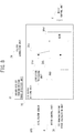
- FIG. 6 illustrates that the output value switching unit 32c switches a state to a state in which the maximum value selection unit 32a is connected with the filter correction value calculation unit 34.
- the delay processing unit 32d depending on a connection state switched by the output value switching unit 32c, conducts, to the peak hold upper limit value or the peak hold lower limit value, the process of delaying by one period of the sampling period set in advance (delay process). Then, the delay processing unit 32d outputs the delayed peak value signal including the peak hold upper limit value or the peak hold lower limit value subjected to the delay process to the maximum value selection unit 32a.
- the Dr override determination signal includes a determination result that the driver override is not established after the constant speed traveling control is stopped, the maximum value of the override amount is held.
- the point of time when the Dr override determination signal including the determination result that the driver override is not established is received corresponds to the point of time when the operation amount of the accelerator pedal AP is zero. Therefore, during the processes conducted by the peak hold processing unit 32, from after the constant speed traveling control is stopped to when the operation amount of the accelerator pedal AP is zero (opening degree of accelerator pedal AP is 0[°], the same applies to the following descriptions), the maximum value of the override amount is held. Note that a state in which the operation amount of the accelerator pedal AP is zero is synonymous with a state in which the driver stopes the operation of the accelerator pedal AP (OFF).
- the override amount is held.
- the filter correction value calculation unit 34 receives a processed peak hold value signal.
- the filter correction value calculation unit 34 stores in advance the filter correction value calculation map.
- the filter correction value calculation map is as illustrated in FIG. 7 , a map indicating a relationship between a peak hold value and a filter correction value. Further, as illustrated in FIG. 7 , the filter correction value calculation map is set in advance such that when the peak hold value exceeds a hold threshold that is a threshold value set in advance, the filter correction value becomes "1.0".
- the peak hold value is the peak hold upper limit value or the peak hold lower limit value included in the processed peak hold value signal.
- the filter correction value changes depending on the change of the peak hold value. Specifically, when the peak hold value is equal to or less than the hold threshold, as the peak hold value decreases, the filter correction value decreases.
- the filter correction value takes a large value.
- the filter correction value is a fixed value, i.e., "1.0".
- the filter correction value is the fixed value, i.e., is "1.0".
- the filter correction value calculation unit 34 inputs the peak hold value to the filter correction value calculation map to calculate the filter correction value.
- the filter correction value calculation unit 34 that has calculated the filter correction value outputs an information signal including the calculated filter correction value (hereinafter sometimes referred to as "filter correction value signal") to the ITS output setting unit 26.
- the ITS output setting unit 26 includes a correction processing unit 26a, a determination condition addition unit 26b, a braking/driving force value switching unit 26c, and a minimum value selection unit 26d.
- the correction processing unit 26a receives, from a driver request driving force detection unit 22, the driver request driving force signal or the driver request braking force signal and receives, from the filter correction unit 24, the filter correction value signal. Additionally, the correction processing unit 26a receives, from the accelerator sensor APS, an information signal including the operation amount of the accelerator pedal AP.
- the correction processing unit 26a conducts the filter processing using the filter correction value included in the filter correction value signal to the driver request driving force or the driver request braking force using the operation amount of the accelerator pedal AP.
- the change in the operation amount of the accelerator pedal AP is detected for each period of the sampling period.
- the filter having a normal time constant set in advance filter processes are conducted on the driver request driving force or the driver request braking force. Accordingly, when the operation amount of the accelerator pedal AP increases, the braking force decreases or the driving force increases depending on the increase in the operation amount of the accelerator pedal AP.
- the normal time constant is set based on, for example, a weight of the vehicle C, a performance of the driving motor DM and the like.
- the filter processes are conducted to the driver request driving force or the driver request braking force using the filter (correction time constant filter) having a time constant (corrected time constant) that is obtained by multiplying the normal time constant by the filter correction value.
- the correction processing unit 26a that has conducted the filter process outputs an information signal including the braking force or the driving force subjected to the filter process (hereinafter sometimes referred to as "filtered braking/driving force signal") to the braking/driving force value switching unit 26c.
- a transfer function between the operation to a decreasing direction of the accelerator pedal AP and the change in the braking/driving force is changed to a direction in which the change in the braking/driving force is delayed.
- the process is conducted by setting the change amount of the driving force and the braking force depending on the operation to the decreasing direction of the accelerator pedal AP by the driver to be smaller than the change amount of the driving force and the braking force depending on the operation to an increasing direction of the accelerator pedal AP by the driver.
- the determination condition addition unit 26b receives, from the accelerator sensor APS, an information signal including the operation amount of the accelerator pedal AP. Additionally, the determination condition addition unit 26b receives, from the motor control unit 4, the Dr override determination signal.
- the determination condition addition unit 26b outputs a first switching signal to the braking/driving force value switching unit 26c when the operation amount of the accelerator pedal AP exceeds zero and when the Dr override determination signal includes a determination result that the driver override is established.
- the determination condition addition unit 26b outputs a second switching signal to the braking/driving force value switching unit 26c when the operation amount of the accelerator pedal AP is zero and when the Dr override determination signal includes a determination result that the driver override is not established.
- first switching signal and the second switching signal are command signals of the processes conducted by the braking/driving force value switching unit 26c.
- the braking/driving force value switching unit 26c is formed using, for example, a switching circuit. Further, the braking/driving force value switching unit 26c can switch a state between a state in which the correction processing unit 26a is connected with the minimum value selection unit 26d and a state in which the ITS braking/driving force calculation unit 20 is connected with the minimum value selection unit 26d.
- the braking/driving force value switching unit 26c refers to the command signals that are received form the determination condition addition unit 26b.
- the braking/driving force value switching unit 26c connects the correction processing unit 26a with the minimum value selection unit 26d.
- the braking/driving force value switching unit 26c connects the ITS braking/driving force calculation unit 20 with the minimum value selection unit 26d.
- the braking/driving force value switching unit 26c that has switched the connection states outputs the filtered braking/driving force signal or the ITS braking/driving force signal to the minimum value selection unit 26d.
- FIG. 8 illustrates that the braking/driving force value switching unit 26c switches a state to a state in which the correction processing unit 26a is connected with the minimum value selection unit 26d.
- the minimum value selection unit 26d receives, from the braking/driving force value switching unit 26c, information signals (filtered braking/driving force signal or the ITS braking/driving force signal) and receives, from the ITS braking/driving force calculation unit 20, the ITS braking/driving force signal.
- the minimum value selection unit 26d compares the braking force or the driving force included in the information signal received from the braking/driving force value switching unit 26c and the braking force or the driving force included in the ITS braking/driving force signal, and from between both, a braking force or a driving force of a minimum value (MIN) is selected (select-low).
- the information signal received from the braking/driving force value switching unit 26c includes a braking force and also the ITS braking/driving force signal includes a braking force, from between both of the braking forces, a smaller braking force is selected.
- the information signal received from the braking/driving force value switching unit 26c includes a driving force and the ITS braking/driving force signal also includes a driving force, from between both of the driving forces, a smaller driving force is selected.
- the minimum value selection unit 26d that has selected the braking force or the driving force of a minimum value outputs an information signal including the braking force or the driving force of the minimum value (hereinafter sometimes referred to as "minimum braking/driving force signal") to the motor control unit 4.
- the minimum value selection unit 26d receives only the ITS braking/driving force signal that is output from the ITS braking/driving force calculation unit 20.
- the minimum braking/driving force signal is the braking force or the driving force included in the ITS braking/driving force signal.
- the motor control unit 4 includes a basic braking/driving force calculation unit 40, a slope detection unit 42, and a braking/driving force correction unit 44. Additionally, the motor control unit 4 includes an arbitration control unit 46, a braking/driving force distribution unit 48, a driving force control unit 50, a first request braking force calculation unit 52, a regenerative braking force control unit 54, and an override determination unit 56.
- the basic braking/driving force calculation unit 40 stores in advance the braking/driving force map.
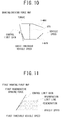
- the braking/driving force map is, as illustrated in FIG. 10 , for example, a map indicating a relationship among the vehicle speed, the operation amount (opening degree) of the accelerator pedal AP, and the torques (driving torque, braking torque) generated to the vehicle C.
- the braking/driving force map illustrated in FIG. 10 is set in advance such that the driving torque and the braking torque have braking/driving force values set in advance when following conditions A1 to A3 are established.
- a slope range is set to be a slope range when the traveling road surface is flat (for example, with a slope zero (0°) as a reference, a range from +0.5° to -0.5°). Further, in the first embodiment, as one example, a case where the braking/driving force value is set to zero is described.
- the stop threshold operation amount is set to zero is described. Further, in the first embodiment, as one example, a case where the stop threshold vehicle speed is set to zero (0[km/h], the same applies to the following descriptions) is described.
- the braking/driving force map illustrated in FIG. 10 is set in advance such that when the traveling road surface is flat and when the operation amount of the accelerator pedal AP and the vehicle speed are zero, the driving torque and the braking torque are zero (0[N ⁇ m]).
- the operation amount (opening degree) of the accelerator pedal AP is denoted with a reference numeral "APO".
- APO opening degree
- T-MIN the torque generated depending on the vehicle speed
- T-MAX the torque generated depending on the vehicle speed
- the driving torque and the braking torque are represented on a longitudinal axis with "0" as a border line.
- the torque denoted with "T-MIN” is the braking torque.
- the torque denoted with "T-MAX” is the driving torque.
- the "basic threshold vehicle speed" illustrated in FIG. 10 in a state where the operation amount of the accelerator pedal AP is a minimum value (unoperated), corresponds to a border line between an area in which the torque generated depending on the vehicle speed decreases (change area) and an area in which the torque generated depending on the vehicle speed is constant (fixed area).
- the basic braking/driving force calculation unit 40 receives, from the accelerator sensor APS, the information signal including the braking/driving force operation amount. Additionally, the basic braking/driving force calculation unit 40 receives, from the vehicle speed calculation unit 14, the vehicle speed signal.
- the basic braking/driving force calculation unit 40 receives, from the mode selection switch 12, the select mode signal. Note that a case where a control mode included in the select mode signal is the "one pedal mode" is described below.
- the basic braking/driving force calculation unit 40 inputs the operation amount of the accelerator pedal AP and the vehicle speed to the braking/driving force map to calculate a target value of the driving torque generated to the vehicle C (target driving torque) or a target value of the braking torque (target braking torque).
- target driving torque and the target braking torque calculated by the basic braking/driving force calculation unit 40 are the target driving torque and the target braking torque when the vehicle C travels on the flat road surface (flat traveling).
- the target driving torque is a torque corresponding to the basic driving force and the target braking torque is a torque corresponding to the basic braking force.
- the basic braking/driving force calculation unit 40 inputs the operation amount of the accelerator pedal AP and the vehicle speed to the braking/driving force map to set the basic braking force and the basic driving force.
- the braking/driving force map illustrated in FIG. 10 includes a change area in which as the vehicle speed decreases (approach zero), the basic braking force decreases.
- the braking/driving force map illustrated in FIG. 10 is set in advance such that when the traveling road surface is flat, and if the operation amount of the accelerator pedal AP is zero and the travelling speed is zero, the basic braking force and the basic driving force are zero.
- the braking/driving force map illustrated in FIG. 10 when the operation amount of the accelerator pedal AP is equal to or less than the stop threshold operation amount (zero in first embodiment), the braking force for stopping the vehicle C is generated.
- the basic braking/driving force calculation unit 40 calculates the basic braking force and the basic driving force.
- the basic braking force depending on the operation amount of the accelerator pedal AP that is less than the threshold value and the travelling speed when the traveling road surface is flat is calculated.
- the operation amount of the accelerator pedal AP is equal to or larger than the threshold value
- the basic driving force depending on the operation amount of the accelerator pedal AP that is equal to or larger than the threshold value and the travelling speed when the traveling road surface is flat is calculated.
- the basic braking/driving force calculation unit 40 inputs, to the braking/driving force map, the operation amount of the accelerator pedal AP and the vehicle speed to calculate the basic braking force and the basic driving force.
- the basic braking/driving force calculation unit 40 when the road surface slope is within the slope range (traveling road surface is flat), sets the braking force generated to the vehicle C to the basic braking force set in advance or sets the driving force generated to the vehicle C to the basic driving force set in advance.
- the basic braking/driving force calculation unit 40 that has calculated the target driving torque outputs an information signal including the calculated target driving torque (hereinafter sometimes referred to as "basic drive torque signal") to the braking/driving force correction unit 44.
- the basic braking/driving force calculation unit 40 that has calculated the target braking torque outputs an information signal including the calculated target braking torque (hereinafter sometimes referred to as "basic braking torque signal") to the braking/driving force correction unit 44.
- control limit gain represented in the braking/driving force map is described in details.
- the hunting may be caused to the current command value of the driving motor DM (motor) . This is because as the inclination angle of the line represented by control limit gain relative to the longitudinal axis representing the torque increases, the degree of change of the deceleration relative to the change in the vehicle speed increases.
- the "response lag" means that by the increase of the degree of change of the deceleration relative to the change in the vehicle speed, the change in the vehicle speed may not follow the sharp change in the deceleration depending on the regenerative braking force and the change in the vehicle speed is delayed relative to the change in the deceleration depending on the regenerative braking force.
- the hunting caused to the current command value When the hunting is caused to the current command value, the variation of the braking force that is different from the driver's request is generated to the decelerating vehicle C and the variation of the vehicle speed that is different from the driver's request is generated.
- the hunting caused to the current command value is generated based on following elements (1. to 6.) for example, in a state where the vehicle C is decelerated while travelling the road surface having a descending slope when the deceleration depending on the regenerative braking force is determined using the braking/driving force map.
- the slope of the line represented by the control limit gain is gentle (if inclination angle is small), relative to the change in the vehicle speed, the deceleration depending on the regenerative braking force does not sharply increase or decrease.
- the occurrence of the phase lag of the change in the vehicle speed is suppressed and it is possible to suppress the hunting caused to the current command value .
- by making small the inclination angle of the line represented by control limit gain it is possible to stabilize the control of the current command value.
- the border line between a state where the control of the current command value is stable and a state where the control of the current command value is unstable corresponds to the line represented by the control limit gain in FIG. 10 .
- the line represented by control limit gain in FIG. 10 is an upper limit of the degree of change of the regenerative braking force depending on the vehicle speed of the vehicle C.
- the inclination angle of the line represented by control limit gain in FIG. 10 is set based on, for example, the performance of the driving motor DM (capability to generate regenerative braking force), the weight of the vehicle C and the like. In other words, the control limit gain illustrated in FIG.
- the 10 is the upper limit of the degree of change of the deceleration depending on the regenerative braking force (basic braking force) relative to the vehicle speed in which the change in the vehicle speed calculated by the vehicle speed calculation unit 14 can follow the change in the deceleration depending on the regenerative braking force (basic braking force).
- the degree of change of the torque represented by "T-MIN" relative to the change in the vehicle speed calculated by the vehicle speed calculation unit 14 is equal to or less than the control limit gain.
- the degree of change of the minimum value of the torque relative to the change in the vehicle speed calculated by the vehicle speed calculation unit 14 is equal to or less than the control limit gain.
- the degree of change of the basic braking force depending on the change of the vehicle speed in the change area is equal to or less than the control limit gain that is the degree of change set in advance.
- the slope detection unit 42 stores in advance a relationship between the driving torque to be generated for a flatland (flat road) and the revolution speed of the wheel as a reference (flatland reference). Note that a relationship between the driving torque to be generated for the flat road and the revolution speed of the wheel is, for example, calculated using the test road surface formed to a slope within the rage corresponding to the flat road, and the slope detection unit 42 stores the relationship as the flatland reference.
- the slope detection unit 42 receives, from the driving force control unit 50, a driving torque signal including the driving current command value and receives, from the wheel speed sensor 16, the wheel speed signal including the revolution speed of the wheel. Further, the slope detection unit 42 receives, from the motor rotation speed sensor MS, the output shaft rotation speed signal.
- the output shaft rotation speed signal is an information signal including the rotation speed of the motor driving force output shaft (not illustrated) of the driving motor DM.
- the slope detection unit 42 calculates a relationship between the current driving torque that is calculated using the current command value and the revolution speed of the wheel W (current relationship). Further, the magnitude of the road surface slope is detected using the degree of deviation between the calculated current relationship and the flatland reference stored by the slope detection unit 42.
- the road surface slope is the upward slope. Additionally, as the revolution speed of the wheel W is slow, the upward slope is detected as the large upward slope.
- the road surface slope is determined to be the descending slope. Additionally, as the revolution speed of the wheel W is fast, the descending slop is detected as the large descending slop.
- the slope detection unit 42 detects a direction of road surface slope along which the vehicle C travels and the magnitude of the road surface slope.
- the slope detection unit 42 determines whether or not the direction of the road surface slope along which the vehicle C travels is an upstream direction or a downward direction.
- the slope detection unit 42 that has detected the direction and the magnitude of the road surface slope outputs an information signal including the detected direction and magnitude of the slope (hereinafter sometimes referred to as “road surface slope signal") to the braking/driving force correction unit 44.
- the braking/driving force correction unit 44 receives information signals from the accelerator sensor APS, the basic braking/driving force calculation unit 40, the slope detection unit 42, the vehicle speed calculation unit 14, and the ITS control unit 2.
- the braking/driving force correction unit 44 corrects the target driving torque of the flat traveling included in the basic drive torque signal or the target braking torque of the flat traveling included in the basic braking torque signal using various received information signals.
- the braking/driving force correction unit 44 that has corrected the target driving torque of the flat traveling included in the basic drive torque signal outputs the corrected driving force signal to the arbitration control unit 46 as an information signal including the driving force (corrected driving force) depending on the corrected driving torque. Additionally, the braking/driving force correction unit 44 outputs the corrected driving force signal to the override determination unit 56 and the driver request braking/driving force detection unit 22.
- the braking/driving force correction unit 44 that has corrected the target braking torque of the flat traveling included in the basic drive torque signal outputs the corrected braking force signal to the arbitration control unit 46 as an information signal including the braking force (corrected braking force) depending on the corrected braking torque. Additionally, the braking/driving force correction unit 44 outputs the corrected braking force signal to the override determination unit 56 and the driver request braking/driving force detection unit 22.
- the braking/driving force correction unit 44 when the traveling road surface is not flat, depending on the direction and the magnitude of the slope, corrects the basic braking force to calculate the corrected braking force and sets the braking force of the vehicle C to the corrected braking force. Further, the braking/driving force correction unit 44, when the traveling road surface is not flat, depending on the direction and the magnitude of the slope, corrects the basic driving force to calculate the corrected driving force and sets the driving force of the vehicle C to the corrected driving force.
- the braking/driving force correction unit 44 corrects the basic braking force or the basic driving force depending on the direction of the road surface slope and the magnitude of the slope and then calculates the corrected braking force or the corrected driving force. Further, the braking/driving force correction unit 44 sets the corrected braking force or the corrected driving force such that when the operation amount of the accelerator pedal AP is less than the threshold value, the braking force (deceleration) is caused to the vehicle C and alternatively when the operation amount of the accelerator pedal AP is equal to or larger than the threshold value, the driving force (acceleration) is caused to the vehicle C.
- the braking/driving force correction unit 44 corrects the basic braking force and the basic driving force calculated by the braking/driving force map depending on a balance torque by continuously increasing or decreasing the basic braking force and the basic driving force.
- the balance torque is a torque enabling the vehicle C to maintain the stopped state on the traveling road surface. Further, the balance torque is calculated based on, for example, the weight of the vehicle C, the capability to generate the driving force, the capability to generate the regenerative braking force, and the capability to generate the friction braking force.
- the braking/driving force correction unit 44 corrects the basic braking force depending on the direction of the road surface slope and the magnitude of the slope and sets the corrected braking force. Further, the braking/driving force correction unit 44 corrects the basic driving force depending on the direction of the road surface slope and the magnitude of the slope and sets the corrected driving force.
- the slope detection unit 42 determines that the direction of the road surface slope is the upstream direction and when the magnitude of the slope detected by the slope detection unit 42 increases in the upstream direction, the slope detection unit 42 sets the braking force generated to the vehicle C to the corrected braking force that is obtained by correcting and decreasing the basic braking force depending on the magnitude of the slope. Further, the slope detection unit 42 sets the driving force generated to the vehicle C to the corrected driving force that is obtained by correcting and increasing the basic driving force depending on the magnitude of the slope.
- the slope detection unit 42 determines that the direction of the road surface slope is the downward direction and when the magnitude of the slope detected by the slope detection unit 42 increases in the downward direction, the slope detection unit 42 sets the braking force generated to the vehicle C to the corrected braking force that is obtained by correcting and increasing the basic braking force based on the magnitude of the slope. Further, the slope detection unit 42 sets the driving force generated to the vehicle C to the corrected driving force that is obtained by correcting and decreasing the basic driving force based on the magnitude of the slope.
- a state where the direction of the road surface slope increases in the upstream direction includes a state where the traveling road surface changes from the flat road to an uphill and a state where the traveling road surface changes from the uphill to an uphill having a larger slope in the upstream direction. Additionally, a state where the direction of the road surface slope increases in the upstream direction includes a state where the traveling road surface changes from the downhill to a downhill having a smaller slope in the downstream direction.
- a state where the direction of the road surface slope increases in the downward direction includes a state where the traveling road surface changes from the flat road to a downhill and a state where the traveling road surface changes from the downhill to a downhill having a larger slope in the downward direction. Additionally, a state where the direction of the road surface slope increases in the downward direction includes a state where the traveling road surface changes from the uphill to the uphill having a smaller slope in the upward direction.
- the arbitration control unit 46 receives the corrected driving force signal or the corrected braking force signal, and the corrected ITS output signal.
- the arbitration control unit 46 compares a parameter subjected to the filter process by the ITS output setting unit 26 with a parameter included in the corrected driving force signal and selects the driving force or the braking force to be output to the braking/driving force distribution unit 48.
- the arbitration control unit 46 compares the driving force included in the corrected driving force signal with the driving force included in the corrected ITS braking/driving force.
- the arbitration control unit 46 selects a larger driving force (select-high) and outputs an information signal including the selected driving force (hereinafter sometimes referred to as "arbitration driving force signal") to the braking/driving force distribution unit 48.
- the arbitration control unit 46 compares the braking force included in the corrected braking force signal with the braking force included in the corrected ITS braking/driving force.
- the arbitration control unit 46 selects a larger braking force (select-high) and outputs an information signal including the selected braking force (hereinafter sometimes referred to as "arbitration braking force signal") to the braking/driving force distribution unit 48.
- the braking/driving force distribution unit 48 When the braking/driving force distribution unit 48 receives, from the arbitration control unit 46, the arbitration driving force signal, the braking/driving force distribution unit 48 outputs an information signal similar to the arbitration driving force signal (hereinafter sometimes referred to as "driving force distribution signal") to the driving force control unit 50.
- driving force distribution signal an information signal similar to the arbitration driving force signal
- the braking/driving force distribution unit 48 When the braking/driving force distribution unit 48 receives, from the arbitration control unit 46, the arbitration braking force signal, the braking/driving force distribution unit 48 outputs an information signal similar to the arbitration braking force signal (hereinafter sometimes referred to as "braking force distribution signal") to the first request braking force calculation unit 52.
- braking force distribution signal an information signal similar to the arbitration braking force signal
- the driving force control unit 50 receives information signals from the braking/driving force distribution unit 48 and the vehicle speed calculation unit 14.
- the driving force control unit 50 refers to the driving force included in the driving force distribution signal and the vehicle speed included in the vehicle speed signal and calculates the driving current command value.
- the driving current command value is a current command value for generating, at the driving motor DM, the driving torque depending on the driving force included in the driving force distribution signal.
- the driving force control unit 50 outputs an information signal including the calculated driving current command value (hereinafter sometimes referred to as “driving torque signal”) to the slope detection unit 42 and an inverter INV.
- the first request braking force calculation unit 52 stores in advance the first braking force map illustrated in FIG. 11 .
- the first braking force map is a map indicating the regenerative braking force generated depending on the vehicle speed and the deceleration depending on the regenerative braking force.
- the "regeneration” illustrated in FIG. 11 is a region corresponding to the regenerative braking force.
- the “regeneration limit line” illustrated in FIG. 11 is a line representing the upper limit of the regenerative braking force depending on the vehicle speed.
- the "first threshold vehicle speed” in FIG. 11 corresponds to the border line between the change area in which the upper limit of the regenerative braking force changes depending on the change in the vehicle speed and the fixed area in which the upper limit of the regenerative braking force is constant.
- the first threshold vehicle speed is set to, for example, 10[km/h].
- the change area in the first braking force map is an area in which the request value (request) of the regenerative braking force changes relative to the change in the vehicle speed calculated by the vehicle speed calculation unit 14.
- the first braking force map is a map for determining the regenerative braking force (regeneration amount) generated at the driving motor DM by feeding back the vehicle speed calculated by the vehicle speed calculation unit 14. Accordingly, the first braking force map indicates that when the vehicle speed changes, the deceleration changes also.
- the regeneration limit line is values for generating the regenerative braking force for stopping the vehicle C when the traveling road surface on which the vehicle C travels is flat (flat road) and only when the vehicle C travels, i.e., the vehicle speed exceeds "0[km/h]".
- the regeneration limit line used for the flat traveling in FIG. 11 is a line representing the upper limit of the regenerative braking force depending on the vehicle speed in a state where the vehicle speed is "0[km/h]" and the deceleration and the regenerative braking force are zero.
- the first request braking force calculation unit 52 refers to the corrected braking force included in the braking force distribution signal that is received from the braking/driving force distribution unit 48 and the vehicle speed included in the vehicle speed signal that is received from the vehicle speed calculation unit 14 and calculates the deceleration generated to the vehicle C.
- the first request braking force calculation unit 52 calculates the first regenerative braking force as the regenerative braking force depending on the calculated deceleration, and outputs an information signal including the first regenerative braking force (hereinafter sometimes referred to as "first braking request signal") to the friction braking force control unit 6.
- the vehicle speed included in the vehicle speed signal and the corrected braking force included in the braking force distribution signal are fed back and the first regenerative braking force is calculated.
- the first request braking force calculation unit 52 calculates the first regenerative braking force depending on the corrected braking force obtained by correcting the basic braking force based on the direction of the road surface slope and the magnitude of the slope.
- the operation amount of the accelerator pedal AP that is equal to or less than the braking/driving force switching operation amount corresponds to the operation amount of the accelerator pedal AP that is less than the threshold value set in advance.
- the first request braking force calculation unit 52 calculates the first regenerative braking force (request value of regenerative braking force) depending on the operation amount of the accelerator pedal AP that is equal to or less than the braking/driving force switching operation amount (i.e. less than the threshold value set in advance) and the travelling speed of the vehicle C.
- the first request braking force calculation unit 52 calculates the first regenerative braking force with the regeneration limit line as the upper limit such that when the operation amount of the accelerator pedal AP detected by the accelerator sensor APS is within the braking range, until the vehicle C is stopped, the vehicle speed calculated by the vehicle speed calculation unit 14 decreases. In other words, the first request braking force calculation unit 52 calculates the regenerative braking force for stopping the vehicle C depending on the operation amount of the accelerator pedal AP when the operation amount of the accelerator pedal AP is equal to or less than the braking/driving force switching operation amount.
- the regenerative braking force control unit 54 receives, from the friction braking force control unit 6, the regeneration request value signal. Additionally, from a battery BAT, a current State Of Charge (SOC) is acquired. The regenerative braking force control unit 54 refers to the request value of regenerative braking force included in the regeneration request value signal and the current state of charge of the battery BAT and calculates the regenerative execution amount.
- SOC State Of Charge
- a regenerative request amount is a target value of the regenerative braking force generated to the driving motor DM.
- the regenerative execution amount is the regenerative braking force that is actually generated at the driving motor DM.
- the calculation is made by assuming that the regenerative execution amount is zero.
- the regenerative braking force control unit 54 that has calculated the regenerative execution amount calculates the regenerative current command value.
- the regenerative current command value is a current command value for generating the regenerative torque by the driving motor DM depending on the regenerative execution amount.
- the regenerative braking force control unit 54 that has calculated the regenerative current command value outputs an information signal including the calculated regenerative current command value (hereinafter sometimes referred to as "regenerative torque signal") to the inverter INV and the friction braking force control unit 6.
- the regenerative braking force control unit 54 generates, at the driving motor DM, the regenerative braking force depending on request value (request) of the regenerative braking force calculated by the friction braking force control unit 6.
- the request value (request) of regenerative braking force calculated by the friction braking force control unit 6 is the request value (request) of regenerative braking force selected by a regenerative coordination control unit 64 described later.
- the override determination unit 56 receives the corrected driving force signal or the corrected braking force signal, and the corrected ITS output signal.
- the override determination unit 56 determines whether or not the driver override is established based on the corrected ITS braking/driving force included in the corrected ITS output signal, the driving force included in the corrected driving force signal, and the braking force included in the corrected braking force signal.
- the override determination unit 56 that has determined whether or not the driver override is established outputs the Dr override determination signal as an information signal including the determination result to the filter correction unit 24 of the ITS control unit 2.
- the driver override indicates a state where the driver of the vehicle C has the control right of the driving force or the braking force of the vehicle C.
- the driver override indicates a state where, for example, the driving force (driving force depending on operation amount of accelerator pedal AP) intended by the driver of the vehicle C is larger than the driving force selected by the ITS output setting unit 26.
- the determination as to whether or not the driver override is established is made by comparing the parameter subjected to the filter process by the ITS output setting unit 26 and the parameter included in the corrected driving force signal.
- the determination is made that the driver override is established. Further, when the braking force included in the corrected braking force signal exceeds the braking force subjected to the filter process by the ITS output setting unit 26, the determination is made that the driver override is established.
- the friction braking force control unit 6, as illustrated in FIG. 12 includes a second request braking force calculation unit 60, a request braking force summation unit 62, a regenerative coordination control unit 64, a friction braking force calculation unit 66, and a braking hydraulic pressure control unit 68.
- the second request braking force calculation unit 60 receives, from the brake sensor BPS, an information signal including the operation amount of the brake pedal BP (braking force operation amount). Additionally, the second request braking force calculation unit 60 receives, from the vehicle speed calculation unit 14, the vehicle speed signal.
- the brake pedal BP is a pedal pedaled by the driver of the vehicle C only in response to the braking force request and is provided separately from the accelerator pedal AP.
- the second request braking force calculation unit 60 stores in advance a second braking force map illustrated in FIG. 13 .
- the second braking force map is a map indicating the braking force (regenerative braking force, friction braking force) that is generated depending on the operation amount of the brake pedal BP and the travelling speed (vehicle speed) of the vehicle C.
- the "regeneration” in FIG. 13 is the region corresponding to the regenerative braking force.
- the “friction” in FIG. 13 is the region corresponding to the friction braking force.
- the "regenerative coordination distribution line” in FIG. 13 is a line representing the upper limit of the regenerative braking force depending on the operation amount of the brake pedal BP and the vehicle speed.
- the "second threshold vehicle speed" in FIG. 13 corresponds to a border line between the change area in which the upper limit of the regenerative braking force changes depending on the change in the vehicle speed and the fixed area in which the upper limit of the regenerative braking force is constant.
- the second threshold vehicle speed is set to, for example, 10[km/h].
- the change area in the second braking force map is the area in which the request value of regenerative braking force changes relative to the change in the vehicle speed calculated by the vehicle speed calculation unit 14.
- control limit gain in FIG. 13 is the upper limit of the degree of change of the regenerative braking force depending on the vehicle speed not greater than the second threshold vehicle speed.
- the line represented by control limit gain in FIG. 13 corresponds to a border line between a state where the control of the current command value is stable and a state where the control of the current command value is unstable.
- the control limit gain in FIG. 13 is the upper limit of the degree of change of the deceleration depending on the regenerative braking force relative to the vehicle speed in which the change in the vehicle speed calculated by the vehicle speed calculation unit 14 can follow the change in the deceleration depending on the regenerative braking force.
- the degree of change of the request value of regenerative braking force (deceleration depending on regenerative braking force) relative to the change in the vehicle speed calculated by the vehicle speed calculation unit 14 is equal to or less than the control limit gain.
- the "regeneration limit vehicle speed" in FIG. 13 corresponds to the border line between the region in which the braking force depending on the operation amount of the brake pedal BP and the vehicle speed is generated only with the friction braking force and the region in which the braking force depending on the operation amount of the brake pedal BP and the vehicle speed is generated at least with the regenerative braking force out of the regenerative braking force and the friction braking force.
- the regeneration limit vehicle speed is set to a value for generating the braking force that depends on the operation amount of the brake pedal BP and the vehicle speed only with the friction braking force when the vehicle C decelerates and in a state where the vehicle speed is larger than zero, i.e., in a state before the travelling vehicle C stops.
- the regeneration limit vehicle speed for example, 3[km/h]
- the power consumed by the driving motor DM to generate the regenerative braking force exceeds the power generated by the regenerative braking force, as the entire vehicle, the energy efficiency is lowered.
- the friction braking force is preferably used rather than using the regenerative braking force to have a good energy efficiency.
- the friction braking force is generated.
- the regenerative coordination distribution line is a value for generating the regenerative braking force only when the vehicle C is travelling.
- the second request braking force calculation unit 60 refers to the operation amount of the brake pedal BP and the vehicle speed included in the vehicle speed signal and calculates a second braking request that is a request (request value) of the braking force depending on the operation amount of the brake pedal BP and the vehicle speed.
- the second braking request includes at least one of the request values out of the request value of the regenerative braking force (second regenerative braking force) and the request value of the friction braking force that depend on the operation amount of the brake pedal BP and the vehicle speed.
- the request values of the regenerative braking force and the friction braking force depending on the operation amount of the brake pedal BP and the vehicle speed are calculated by feeding back, to the second braking force map in FIG. 13 , for example, the vehicle speed included in the vehicle speed signal and the braking force depending on the operation amount of the brake pedal BP. Note that when the vehicle speed included in the vehicle speed signal exceeds the second threshold vehicle speed, the calculation is made by assuming that the request value of the friction braking force is zero.
- the second request braking force calculation unit 60 that has calculated the second braking request outputs an information signal including the second braking request (hereinafter sometimes referred to as "second braking request signal") to the request braking force summation unit 62.
- the second request braking force calculation unit 60 calculates the request value (request) of the regenerative braking force (second regenerative braking force) based on the operation amount of the brake pedal BP and the travelling speed of the vehicle C with the regenerative coordination distribution line as the upper limit. Additionally, when the brake pedal BP is operated, the second request braking force calculation unit 60 calculates the braking force exceeding the regenerative coordination distribution line as the request value (request) of the friction braking force based on the operation amount of the brake pedal BP and the travelling speed of the vehicle C.
- the second request braking force calculation unit 60 calculates the second braking request such that a portion of the braking forces depending on the operation amount of the brake pedal BP detected by the brake sensor BPS, the braking force exceeding the regenerative coordination distribution line is generated with the friction braking force.
- the second request braking force calculation unit 60 only when the vehicle speed exceeds the regeneration limit vehicle speed, with the regenerative coordination distribution line as the upper limit, calculates the second regenerative braking force.
- the request braking force summation unit 62 receives, from the first request braking force calculation unit 52 and the second request braking force calculation unit 60, information signals.
- the request braking force summation unit 62 outputs an information signal including the first regenerative braking force (hereinafter sometimes referred to as "first regenerative signal”) to the regenerative coordination control unit 64. Further, the request braking force summation unit 62, when the second braking request includes the second regenerative braking force, outputs an information signal including the second regenerative braking force (hereinafter sometimes referred to as "second regenerative signal”) to the regenerative coordination control unit 64.
- the request braking force summation unit 62 sums the first regenerative braking force included in the first braking request signal and the second braking request included in the second braking request signal. In other words, the request braking force summation unit 62 sums the first regenerative braking force calculated by the first request braking force calculation unit 52 and the second regenerative braking force and the friction braking force that are calculated by the second request braking force calculation unit 60.
- the request braking force summation unit 62 that has summed each of the braking forces outputs an information signal including the request value (summation request braking force) of the summed braking force (hereinafter sometimes referred to as "sum braking force signal") to the friction braking force calculation unit 66.
- the regenerative coordination control unit 64 receives, from the request braking force summation unit 62, either one of the first regenerative signal and the second regenerative signal.
- the regenerative coordination control unit 64 uses the summation request braking force included in the sum braking force signal, selects the request value (upper limit) of the regenerative braking force.
- the regenerative coordination control unit 64 that has selected the request value of regenerative braking force outputs a regeneration request value signal that is an information signal including the selected request value to the regenerative braking force control unit 54.
- the regenerative coordination control unit 64 compares the first regenerative braking force included in the first regenerative signal with the second regenerative braking force included in the second regenerative signal and selects a larger regenerative braking force (select-high). Then, the regenerative coordination control unit 64 selects this regenerative braking force as the request value of regenerative braking force.
- the regenerative coordination control unit 64 selects the request value of regenerative braking force
- the regenerative coordination control unit 64 inputs to the map illustrated in FIG. 14 , for example, the first regenerative braking force and the second regenerative braking force that depend on the identical vehicle speed.
- the regenerative coordination control unit 64 selects a larger regenerative braking force out of the first regenerative braking force and the second regenerative braking force.
- the map (regenerative braking force selection map) illustrated in FIG. 14 is a map indicating a relationship among the first regenerative braking force, the second regenerative braking force, and the vehicle speed.
- regeneration limit line illustrated in FIG. 14 is similar to the "regeneration limit line” illustrated in FIG. 11 and the "regenerative coordination distribution line” illustrated in FIG. 14 is similar to the "regenerative coordination distribution line” illustrated in FIG. 13 .
- the "regeneration request upper limit" illustrated in FIG. 14 is a line obtained by continuing values each of which is larger one among a value on the regeneration limit line and a value on the regenerative coordination distribution line at the same vehicle speed.
- the “threshold vehicle speed” in FIG. 14 corresponds to the border line between the change area in which the upper limit of the regenerative braking force changes depending on the change in the vehicle speed and the fixed area in which the upper limit of the regenerative braking force is constant.
- the threshold vehicle speed is, as similar to the first threshold vehicle speed and the second threshold vehicle speed, set to, for example, 10[km/h].
- control limit gain illustrated in FIG. 14 is similar to the "control limit gain” illustrated in Figs. 10, 11 , and 13 .
- the “switching vehicle speed” illustrated in FIG. 14 corresponds to the border line between the region in which the regeneration request upper limit is the regeneration limit line and the region in which the regeneration request upper limit is the regenerative coordination distribution line. Further, the “regeneration limit vehicle speed” in FIG. 14 is similar to the “regeneration limit vehicle speed” in FIG. 13 .
- the switching vehicle speed is set in advance based on, for example, the performance ⁇ specification (car weight, performance of driving motor DM and the like) of the vehicle C.
- the regenerative coordination control unit 64 while decelerating, when the brake pedal BP is operated, selects a larger regenerative braking force out of the first regenerative braking force calculated by the first request braking force calculation unit 52 or the second regenerative braking force calculated by the second request braking force calculation unit 60.
- the regeneration request upper limit is equivalent to the regenerative coordination distribution line in the region where the vehicle speed is equal to or greater than the switching vehicle speed. Further, the regeneration request upper limit is equivalent to regeneration limit line in the region where the vehicle speed is less than the switching vehicle speed.
- the regenerative coordination control unit 64 if the vehicle C is travelling (if the vehicle C is not stopped), selects the regeneration request upper limit as a value greater than zero.
- the inclination angle of the line represented by the regeneration request upper limit is equal to or less than the inclination angle of the line represented by the control limit gain even if the vehicle speed is less than the threshold vehicle speed, the switching vehicle speed, and regeneration limit vehicle speed.
- the regenerative coordination control unit 64 selects a larger request value out of the request values calculated by the first request braking force calculation unit 52 and the second request braking force calculation unit 60.
- the regenerative coordination control unit 64 selects a larger regenerative braking force out of the first regenerative braking force and the second regenerative braking force. Note that in the first embodiment, as one example, a case where when the operation amount of the accelerator pedal AP is less than the threshold value, until the vehicle C is stopped, the regenerative braking force is generated and the vehicle speed is decreased is described.
- the friction braking force calculation unit 66 receives, from the request braking force summation unit 62, the sum braking force signal and receives, from the regenerative braking force control unit 54, the regenerative torque signal.
- the friction braking force calculation unit 66 subtracts, from the summation request braking force included in the sum braking force signal, the regenerative execution amount included in the regenerative torque signal and calculates a friction execution amount.
- the friction execution amount is the friction braking force that is actually generated at the wheel W.
- the friction braking force calculation unit 66 that has calculated the friction execution amount calculates the friction braking force command value.
- the friction braking force command value is the target value of the liquid pressure generated at a master cylinder 18 for generating the friction braking force depending on the friction execution amount.
- the friction braking force calculation unit 66 that has calculated the friction braking force command value outputs an information signal including the calculated friction braking force command value (hereinafter sometimes referred to as "friction braking force signal") to the braking hydraulic pressure control unit 68.
- the braking hydraulic pressure control unit 68 outputs the friction braking force command value to the master cylinder 18.
- the master cylinder 18 is a device for supplying, to a wheel cylinder WS, a brake fluid.
- the master cylinder 18 that has received the friction braking force command value actuates the braking motor (not illustrated) or the like built in, for example, the master cylinder 18 to actuate the piston in the master cylinder 18. Accordingly, in the master cylinder 18, the liquid pressure depending on the friction braking force command value is generated. Then, the brake fluid of the liquid pressure depending on the friction braking force command value is supplied to the wheel cylinder WS. Note that detailed configurations of the wheel cylinder WS are described later.
- the friction braking force control unit 6 at the master cylinder 18 and the wheel cylinder WS, generates the friction braking force to the wheel W of the vehicle C.
- the friction braking force control unit 6 generates, at the master cylinder 18 and the wheel cylinder WS, the friction braking force depending on the deviation between the request values summed by the request braking force summation unit 62 and the regenerative braking force generated at the driving motor DM by the regenerative braking force control unit 54.
- the braking/driving force control device 1 conducts, for example, the calculation processes by assuming that the target driving torque is zero.
- the vehicle C having the braking/driving force control device 1 includes the accelerator pedal AP, the accelerator sensor APS, the brake pedal BP, the brake sensor BPS, the wheel speed sensor 16, and the motor rotation speed sensor MS. Additionally, the vehicle C includes the ITS control unit 2, the motor control unit 4, and the friction braking force control unit 6. Further, the vehicle C includes the master cylinder 18, the wheel cylinder WS, the battery BAT, the inverter INV, the driving motor DM, the transmission TR, and the wheel W (a right front wheel WFR, a left front wheel WFL, a right rear wheel WRR, and a left rear wheel WRL).
- Each of the wheel speed sensor 16 is provided to each of the wheel W in a corresponding manner.
- the wheel speed sensor 16 for one revolution of the corresponding wheel W, generates the predetermined number of wheel speed pulses.
- the wheel speed sensor 16 outputs an information signal including the generated wheel speed pulse (hereinafter sometimes referred to as “wheel speed pulse signal”) to the vehicle speed calculation unit 14.
- the wheel speed sensor 16 that generates the wheel speed pulse for one revolution of the right front wheel WFR is represented as the wheel speed sensor 16FR and the wheel speed sensor 16 that generates the wheel speed pulse for one revolution of the left front wheel WFL is represented as the wheel speed sensor 16FL.
- the wheel speed sensor 16 that generates the wheel speed pulse for one revolution of the right rear wheel WRR is represented as the wheel speed sensor 16RR and the wheel speed sensor 16 that generates the wheel speed pulse for one revolution of the left rear wheel WRL is represented as the wheel speed sensor 16RL.
- each of the wheels W and each of the wheel speed sensors 16 may be represented as above.
- the wheel cylinder WS generates the pressing force for pressing the brake pad (not illustrated) included in the disc brake to the disc rotor (not illustrated).
- the disc rotor rotates together with each of the wheels W, contacts the brake pad and generates a friction resistance.
- the master cylinder 18 and each of the wheel cylinders WS are respectively provided to a front wheel WF and a rear wheel WR and form a friction brake that generates the friction braking force to each of the wheels W.
- the friction brake of the vehicle C generates the friction braking force to all of the wheels W (right front wheel WFR, left front wheel WFL, right rear wheel WRR, and left rear wheel WRL).
- the wheel cylinder WS arranged for the right front wheel WFR is represented as the wheel cylinder WSFR and the wheel cylinder WS arranged for the left front wheel WFL is represented as the wheel cylinder WSFL.
- the wheel cylinder WS arranged for the right rear wheel WRR is represented as the wheel cylinder WSRR and the wheel cylinder WS arranged for the left rear wheel WRL is represented as the wheel cylinder WSRL.
- each of the wheel cylinders WS may be represented as above.
- the battery BAT is formed using, for example, a lithium ion battery.
- a battery controller (not illustrated) that can detect a current value, a voltage value, a temperature and the like of the battery BAT is provided.
- the battery controller detects the SOC of the battery BAT and outputs an information signal including the detected SOC to the regenerative braking force control unit 54.
- the power generated by the driving motor DM through the regenerative braking is charged via the inverter INV.
- the inverter INV When the inverter INV receives, from the driving force control unit 50, the driving current command value, the inverter INV outputs the driving current command value included in driving torque signal to the driving motor DM.
- the inverter INV receives, from the regenerative braking force control unit 54, the regenerative torque signal, the inverter INV outputs the regenerative current command value included in the regenerative torque signal to the driving motor DM.
- the driving motor DM When the driving motor DM receives, from the inverter INV, the driving current command value, the driving motor DM generates the driving force depending on the driving current command value.
- the driving force generated by the driving motor DM is, via a drive shaft (not illustrated) or the like, given to each of the wheels W.
- the driving motor DM When the driving motor DM receives, from the inverter INV, the regenerative current command value, the driving motor DM generates the regenerative braking force depending on the driving current command value.
- the regenerative braking force generated by the driving motor DM is given to each of the wheels W via a drive shaft or the like.
- the driving motor DM generates the driving force or the regenerative braking force only to the right front wheel WFR and the left front wheel WFL, i.e., only to the front wheel WF is described.
- the vehicle C of the first embodiment is a vehicle (EV: Electric Vehicle) in which the drive source that generates the driving force is an electric motor. Further, the vehicle C in the first embodiment is a vehicle (2WD vehicle) in which the drive system is a two-wheel drive. In the vehicle C of the first embodiment, the right front wheel WFR and the left front wheel WFL are driving wheels.
- EV Electric Vehicle
- 2WD vehicle vehicle
- the right front wheel WFR and the left front wheel WFL are driving wheels.
- the transmission TR based on the operation state of the shift lever (shift switch) by the driver, switches the travelling ranges (for example, "P: parking” range, “D: drive” range, “R: reverse” range and the like) . Accordingly, the rotation direction and the rotation state of the wheels W are switched.
- the driving force or the regenerative braking force is given.
- the friction braking force is given via the wheel cylinder WS.
- FIG. 15A and FIG. 15B , and FIG. 16 and FIG. 17 one example of a process conducted by the ITS control unit 2, one example of a process conducted by the motor control unit 4, and one example of a process conducted by the friction braking force control unit 6 are described. Note that in the following descriptions, the processes conducted by the ITS control unit 2, the motor control unit 4 and the friction braking force control unit 6 may be referred to as "braking/driving force control process".
- step S100 when the braking/driving force control process is started (START), first a process of a step S100 is conducted.
- the operation state of the mode selection switch 12 is detected. Accordingly, at the step S100, a process of determining whether or not a "one pedal mode" is selected as the control mode of the vehicle C is conducted ("one pedal mode" in the drawing).
- step S100 when it is determined that the "one pedal mode" is selected as the control mode of the vehicle C ("Yes” in the drawing), the braking/driving force control process proceeds to a step S102.
- step S100 when it is determined that the "two pedal mode" is selected as the control mode of the vehicle C ("No" in the drawing), the braking/driving force control process proceeds to a step S146.
- the operation state of the constant speed traveling control setting switch is detected. Accordingly, at the step S102, a process of determining whether or not the "constant speed traveling control" is selected as the control mode of the vehicle C is conducted ("select constant speed traveling control" in the drawing) .
- step S102 when it is determined that the "constant speed traveling control" is selected as the control mode of the vehicle C ("Yes" in the drawing), the braking/driving force control process proceeds to a step S104.
- step S102 when it is determined that the "constant speed traveling control" is not selected as the control mode of the vehicle C ("No" in the drawing), the braking/driving force control process proceeds to step S106.
- the ITS control unit 2 conducts the process necessary for the constant speed traveling control ("constant speed traveling control processing" in the drawing) . After the process necessary for the constant speed traveling control is conducted at the step S104, the braking/driving force control process proceeds to a step S106.
- the motor rotation speed sensor MS detects the rotation speed of the motor driving force output shaft of the driving motor DM. Accordingly, at the step S106, the rotation speed of the driving motor DM is detected ("detect motor rotation speed" in the drawing). After the rotation speed of the driving motor DM is detected at the step S106, the braking/driving force control process to the step S108.
- the slope detection unit 42 detects the driving torque generated to the driving motor DM ("detect motor torque" in the drawing). After the driving torque generated to the driving motor DM is detected at the step S108, the braking/driving force control process proceeds to the step S110.
- each of the wheel speed sensors 16 detects the rotation state of the corresponding wheel W as a wheel speed pulse. Accordingly, at the step S110, the revolution speed of each of the wheels W is detected ("detect wheel speed" in the drawing). After the revolution speed of each of the wheels W is detected at the step S110, the braking/driving force control process proceeds to the step S112.
- the braking/driving force correction unit 44 calculates a parameter for correcting the braking force or the driving force based on the direction and the magnitude of the slope ("calculate slope correction amount" in the drawing) . After a parameter for correcting the braking force or the driving force is calculated based on the direction and the magnitude of the slope at the step S112, the braking/driving force control process proceeds to the step S114.
- the accelerator sensor APS detects the operation amount of the accelerator pedal AP by the driver. Accordingly, at the step S114, the opening degree of the accelerator pedal AP is detected ("detect A pedal opening degree" in the drawing). After the opening degree of the accelerator pedal AP is detected at the step S114, the braking/driving force control process proceeds to the step S116.
- the basic braking/driving force calculation unit 40 calculates the target driving torque or the target braking torque based on the vehicle speed depending on the revolution speed detected at the step S110 and the opening degree of the accelerator pedal AP detected at the step S114.
- the driving torque or the braking torque depending on the braking/driving force map illustrated in FIG. 10 is calculated ("calculate basic braking/driving torque" in the drawing).
- the braking/driving force control process proceeds to the step S118.
- the braking/driving force correction unit 44 calculates the corrected braking force or the corrected driving force ("calculate slope correction braking/driving force" in the drawing). After the corrected braking force or the corrected driving force is calculated at the step S118, the braking/driving force control process proceeds to the step S120.
- the arbitration control unit 46 detects the braking force or the driving force subjected to the filter process by the ITS output setting unit 26 (the "detect ITS braking/driving force" in the drawing). After the braking force or the driving force subjected to the filter process by the ITS output setting unit 26 is detected at the step S120, the braking/driving force control process proceeds to the step S122.
- the arbitration control unit 46 compares an ITS output signal with the corrected driving force signal and selects a larger force out of the driving force or the braking force (select-high) ("braking/driving force arbitration" in the drawing) . After selecting a larger value out of the driving force or the braking force included in the ITS output signal and the corrected driving force signal at the step S122, the braking/driving force control process proceeds to the step S124.
- the determination is made as to whether or not the arbitration control unit 46 selects the braking force at the step S124 ("Dr request is braking" in the drawing).
- step S124 when it is determined that the arbitration control unit 46 selects the braking force at the step S124 ("Yes" in the drawing), the braking/driving force control process proceeds to the step S126.
- step S124 when it is determined that the arbitration control unit 46 selects the driving force at the step S124 ("No" in the drawing), the braking/driving force control process proceeds to the step S142.
- the first request braking force calculation unit 52 calculates the first regenerative braking force depending on the operation amount of the accelerator pedal AP and the vehicle speed. Further, at the step S126, the first braking request signal including the calculated first regenerative braking force is output to the friction braking force control unit 6 ("output first regenerative braking force" in the drawing). After the first braking request signal is output at the step S126, the braking/driving force control process proceeds to the step S128.
- the first regenerative braking force is calculated in the step S126 such that, as illustrated in, for example, FIG. 11 , when vehicle speed is equal to or less than the first threshold vehicle speed, the vehicle speed and also the first regenerative braking force are lowered and when the vehicle speed is zero, the first regenerative braking force also becomes zero.
- the first regenerative braking force that can smoothly stop the vehicle C (Smooth stop: SS) is calculated.
- the brake sensor BPS detects the operation amount of the brake pedal BP by the driver. Accordingly, at the step S128, the operation amount of the brake pedal BP is detected (the "detect brake operation amount" in the drawing). After the operation amount of the brake pedal BP is detected at the step S128, the braking/driving force control process proceeds to the step S130.
- the second request braking force calculation unit 60 calculates the second braking request as a request of the braking force depending on the operation amount of the brake pedal BP by the driver and the vehicle speed (the "calculate driver request braking force" in the drawing). After the second braking request is calculated at the step S130, the braking/driving force control process proceeds to the step S132.
- the request braking force summation unit 62 sums the first regenerative braking force calculated at the step S126 and the second braking request calculated at the step S130 (the "all braking request sum" in the drawing) . After the first regenerative braking force and the second braking request are summed at the step S132, the braking/driving force control process proceeds to the step S134.
- the regenerative coordination control unit 64 compares the first regenerative braking force included in the first regenerative signal received from the request braking force summation unit 62 with the second regenerative braking force included in the second regenerative signal. At the step S134, the regenerative coordination control unit 64 selects a larger regenerative braking force (select-high) and sets the selected regenerative braking force as the request value of the regenerative braking force. Accordingly, at the step S134, the regenerative coordination control unit 64 calculates the request value of the regenerative braking force (the "calculate regeneration request value" in the drawing). After the request value of the regenerative braking force is calculated at the step S134, the braking/driving force control process proceeds to the step S136.
- the regenerative coordination control unit 64 outputs the regeneration request value signal including the request value of the regenerative braking force to the regenerative braking force control unit 54 (the "output regeneration request" in the drawing). After the regeneration request value signal is output to the regenerative braking force control unit 54 at the step S136, the braking/driving force control process proceeds to the step S138.
- the regenerative braking force control unit 54 calculates the regenerative current command value. Further, the regenerative torque signal including the regenerative current command value is output to the inverter INV. Accordingly, at the step S138, the driving motor DM generates the regenerative braking force depending on the regenerative current command value (the "output motor regeneration execution value" in the drawing).
- the regenerative braking force control unit 54 generates a larger regenerative braking force out of the first regenerative braking force and the second regenerative braking force by the driving motor DM when the operation amount of the accelerator pedal AP is less than the threshold value and when the brake pedal BP is operated.
- the braking/driving force control process proceeds to the step S140.
- the friction braking force calculation unit 66 calculates the friction braking force command value and the braking hydraulic pressure control unit 68 outputs the friction braking force command value to the master cylinder 18. Accordingly, at the step S140, the friction braking force depending on the friction braking force command value is generated (the "execute friction braking" in the drawing). After the friction braking force depending on the friction braking force command value is generated at the step S140, the braking/driving force control process is ended (END) .
- the braking/driving force distribution unit 48 outputs, to the driving force control unit 50, the driving force distribution signal (the "drive request output” in the drawing) .
- the driving force distribution signal is output to the driving force control unit 50 at the step S142, the braking/driving force control process proceeds to the step S144.
- the driving force control unit 50 calculates the driving current command value and outputs the calculated driving torque signal to the inverter INV. Accordingly, the driving force depending on the driving current command value is generated by the driving motor DM at the step S144 (the "execute drive control" in the drawing) . After the driving force depending on the driving current command value is generated at the step S144, the braking/driving force control process is ended (END).
- the braking force and the driving force of the vehicle C are controlled depending on the "two pedal mode" (the “braking/driving force control execution for two pedal mode” in the drawing) . Note that since the control of the braking force and the driving force depending on the "two pedal mode” is the known technology, descriptions of the control are omitted.
- the braking/driving force control process is ended (END).
- step S200 is conducted.
- the driver request braking/driving force detection unit 22 detects the driver request driving force or the driver request braking force (the "detect driver request braking/driving force" in the drawing). After the driver request driving force or the driver request braking force is detected at the step S200, the constant speed traveling control process proceeds to the step S202.
- the ITS braking/driving force calculation unit 20 calculates the driving force or the braking force generated to the vehicle C depending on the speed difference between the set speed and the vehicle speed (the "calculate ITS braking/driving force" in the drawing) .
- the constant speed traveling control process proceeds to the step S204.
- the determination is made as to whether or not the driver override is established (the "IS override established ?" in the drawing).
- step S204 it is determined that the driver override is established ("Yes" in the drawing), the constant speed traveling control process proceeds to the step S206.
- step S204 when it is determined that the driver override is not established ("No" in the drawing), the constant speed traveling control process proceeds to the step S208.
- the filter correction unit 24 corrects the ITS braking/driving force filter and calculates the filter correction value (the "calculate filter correction value" in the drawing). After the filter correction value is calculated at the step S206, the constant speed traveling control process proceeds to the step S212.
- the ITS output setting unit 26 selects any one of the braking force or the driving force included in the ITS braking/driving force signal, the driver request driving force, and the driver request braking force (the "select braking/driving force" in the drawing). After one of the braking force or the driving force included in the ITS braking/driving force signal, the driver request driving force, and the driver request braking force is selected at the step S208, the constant speed traveling control process proceeds to the step S210.
- the ITS output setting unit 26 conducts the filter process to any one of the braking force, the driving force, the driver request driving force, and the driver request braking force selected at the step S208 using the filter correction value calculated at the step S206. Accordingly, at the step S210, any one of the braking force, the driving force, the driver request driving force, and the driver request braking force selected at the step S208 is corrected.
- the corrected ITS output signal including the corrected ITS braking/driving force that is the corrected value is output to the motor control unit 4 (the "output corrected braking/driving force" in the drawing).
- the constant speed traveling control process is ended (END).
- the ITS output setting unit 26 selects any one of the braking force or the driving force included in the ITS braking/driving force signal, the driver request driving force, and the driver request braking force (the "select braking/driving force" in the drawing) . After one of the braking force or the driving force included in the ITS braking/driving force signal, the driver request driving force, and the driver request braking force is selected at the step S212, the constant speed traveling control process proceeds to the step S214.
- the ITS output setting unit 26 outputs, to the motor control unit 4, the corrected ITS output signal including any one of the braking force, the driving force, the driver request driving force, and the driver request braking force selected at the step S212 ("output braking/driving force" in the drawing).
- the corrected ITS output signal is output to the motor control unit 4 at the step S214, the constant speed traveling control process is ended (END).
- filter correction value calculation process details of the process conducted at the above described step S206 are described (hereinafter sometimes referred to as "filter correction value calculation process").
- step S300 is conducted.
- the override amount calculation unit 30 detects the set speed ("detect set speed" in the drawing) . After the set speed is detected at the step S300, the filter correction value calculation process proceeds to the step S302.
- the override amount calculation unit 30 detects the travelling speed (vehicle speed) of the vehicle C (the vehicle) ("detect vehicle speed" in the drawing). After the travelling speed of the vehicle C is detected at the step S302, the filter correction value calculation process proceeds to the step S304.
- the override amount calculation unit 30 subtracts, from the travelling speed detected at the step S302, the set speed detected at the step S300 and calculates the deviation amount. Further, at the step S304, the override amount calculation unit 30 inputs the calculated deviation amount to the override amount calculation map to calculate the override amount ("calculate override amount" in the drawing) . After the override amount is calculated at the step S304, the filter correction value calculation process proceeds to the step S306.
- the peak hold processing unit 32 calculates the peak hold upper limit value or the peak hold lower limit value ("calculate peak hold value" in the drawing) . After the peak hold upper limit value or the peak hold lower limit value is calculated at the step S306, the filter correction value calculation process proceeds to the step S308.
- the filter correction value is calculated. After the filter correction value is calculated at the step S308, the filter correction value calculation process is ended (END).
- FIGS. 18A and 18B illustrate a time chart of the operations conducted with a configuration applied with the braking/driving force control device 1 according to the first embodiment.
- FIG. 18B illustrates a time chart of the operations conducted with a configuration not applied with the braking/driving force control device 1 according to the first embodiment.
- FIGS. 18A and 18B illustrate a state where the vehicle C travels on the flat road surface (flat road) .
- the time chart illustrated in FIGS. 18A and 18B start from a state where the driver does not operate the accelerator pedal AP and the ITS control unit 2 conducts the control (constant speed traveling control) to make the vehicle C travel at the set speed.
- the time chart illustrated in FIGS. 18A and 18B start from a state where the driver operates the constant speed traveling control setting switch and selects the conduction of the constant speed traveling control.
- the driving force generated to the vehicle C As to the driving force generated to the vehicle C, the driving force depending on the operation amount of the accelerator pedal AP by the driver is compared with the driving force calculated by the constant speed driving force calculation unit 20. Then, a larger driving force is selected (select-high) to set the driving force generated to the vehicle C.
- the braking/driving force depending on the operation amount of the accelerator pedal AP by the driver is represented as the "driver request braking/driving force”.
- the braking/driving force calculated by the ITS control unit 2 is represented as the "ITS braking/driving force”.
- the operation amount (opening degree) of the accelerator pedal AP is denoted with the reference numeral "APO".
- the driving force calculated by the constant speed driving force calculation unit 20 is set as the driving force generated to the vehicle C.
- the driver override is not established.
- the point of time t2 is a point of time when a value of the driving force of the driver request braking/driving force that increases together with the "APO" is equal to a value of a driving force of the ITS braking/driving force.
- the driving force of the ITS braking/driving force that is a larger driving force is selected out of the driving force of the driver request braking/driving force and the driving force of the ITS braking/driving force as the driving force generated to the vehicle C (select-high).
- the driver request braking/driving force is equal to or less than the ITS braking/driving force, i.e., during a period from the point of time when the time chart is started to the point of time t2, the driving force depending on the ITS braking/driving force is generated.
- the driver override is established.
- the driving force or the braking force of the driver request braking/driving force is selected as the driving force or the braking force generated at the vehicle C.
- the correction processing unit 26a uses the filter having the normal time constant, conducts the filter process to the driver request driving force. Accordingly, the driving force is increased depending on the increase in the "APO".
- the driving force is increased depending on the increase in the operation amount. Accordingly, the driving force depending on the driving force of the driver request braking/driving force (driver demand torque) is generated.
- the "APO” that increases at or after the point of time t2 changes to a decreasing state, and from the point of time (the point of time t3) when the state of the "APO” changes from the increasing state to the decreasing state, depending on the decrease in the "APO", the driving force of the driver request braking/driving force decreases.
- the driving force decreases or the braking force increases.
- the correction processing unit 26a when the driver override is established, the correction processing unit 26a, using the correction time constant filter having the corrected time constant, conducts the filter process to the driver request driving force.
- the correction processing unit 26a using the correction time constant filter having the corrected time constant, conducts the filter process to the driver request driving force.
- the driving force is decreased depending on the decrease in the "APO", such that a change rate of the driving force is smaller than that when the filter having the normal time constant is used.
- the driving force is decreased or the braking force is increased.
- the transfer function between the operation in the decreasing direction of the accelerator pedal AP and the change in the braking/driving force is changed to the direction in which the change in the braking/driving force is delayed.
- the decreased amount of the driving force and the increased amount of the braking force per unit time are controlled to be smaller than the decreased amount of the driving force and the increased amount of the braking force per unit time when the constant speed traveling control is not conducted.
- the change amount of the driving force and the braking force is set so as to be reduced depending on the peak hold value calculated at the above described step S306 compared to when the constant speed traveling control is not conducted.
- the transfer function between the operation in the decreasing direction of the accelerator pedal AP and the change in the braking/driving force is changed to a direction in which the change in the braking/driving force is delayed.
- the maximum value of the override amount is held after the constant speed traveling control is stopped until the operation amount of the accelerator pedal AP becomes zero.
- the change amount of the driving force and the braking force is set to be reduced depending on the held maximum value of the override amount compared to when the constant speed traveling control is not conducted.
- the change amount of the driving force and the braking force is set.
- the driving force decreases at a large change rate.
- the driving force of the ITS braking/driving force is selected as the driving force generated at the vehicle C.
- the driving force that has decreased from the point of time t3 increases to become the driving force of the ITS braking/driving force.
- the driving force is decreased based on the decrease in the "APO" such that the change rate of the driving force is smaller than that when the filter having the normal time constant is used.
- the braking/driving force control device 1 according to the first embodiment has the smaller change amount of the braking/driving force rather than a configuration not applied with the braking/driving force control device 1 according to the first embodiment during a period from the point of time t3 to the point of time t4.
- the change amount of the braking/driving force (only driving force) from the point of time t3 to the point of time t4 is represented as the "braking/driving force change amount A”.
- the change amount of the braking/driving force (driving force and braking force) from the point of time t3 to the point of time t4 is represented as the "braking/driving force change amount B”.
- the "braking/driving force change amount A" is smaller than the "braking/driving force change amount B".
- the braking/driving force control device 1 according to the first embodiment has the smaller change amount in the braking/driving force rather than a configuration not applied with the braking/driving force control device 1 according to the first embodiment during a period from the point of time t4 to a point of time (point of time t6) when the "generated braking/driving force" increases up to the driving force of the ITS braking/driving force.
- the braking/driving force control device 1 according to the first embodiment can more effectively suppress the variation in the braking/driving force generated to the vehicle C rather than a configuration not applied with the braking/driving force control device 1 according to the first embodiment.
- the deceleration control depending on the operation amount of the accelerator pedal AP is conducted and even when the operation amount of the accelerator pedal AP becomes zero, the discomfort given to the driver can be reduced.
- the ITS control unit 2 the driving force control unit 50, the friction braking force control unit 6, and the regenerative braking force control unit 54, during the constant speed traveling control, when the driver demand torque is equal to or less than the target driving torque, generate the driving force depending on the target driving torque.
- the transfer function between the operation in the decreasing direction of the accelerator pedal AP and the change in the braking/driving force is changed to a direction in which the change in the braking/driving force is delayed.
- the operation amount of the accelerator pedal AP becomes zero after the driver demand torque exceeds the target driving torque, a state returns to a state where the driving force depending on the target driving torque is generated.
- the ITS control unit 2 when the driver demand torque is equal to or less than the target braking/driving torque, the ITS control unit 2, the driving force control unit 50, the friction braking force control unit 6, and the regenerative braking force control unit 54 control the acceleration/deceleration of the vehicle depending on the target braking/driving torque. Further, when the driver demand torque exceeds the target braking/driving torque, the ITS control unit 2, the driving force control unit 50, the friction braking force control unit 6, and the regenerative braking force control unit 54, control the acceleration/deceleration depending on the driver demand torque.
- the driver demand torque is decreased depending on the decrease in the operation amount of the accelerator pedal AP.
- the decrease rate of the driver demand torque depending on the decrease in the operation amount of the accelerator pedal AP is set to be smaller than the decrease rate of the driver demand torque depending on the operation amount of the accelerator pedal AP when the driver does not set the travelling speed.
- the acceleration/deceleration is controlled depending on the set driver demand torque, and when the operation amount of the accelerator pedal AP becomes zero, a state is returned to a state where the acceleration/deceleration is controlled depending on the target braking/driving torque.
- driver request braking/driving force corresponds to a driver demand torque.
- the above described target driving torque and target braking torque correspond to target braking/driving torques.
- the above described wheel speed sensor 16 and vehicle speed calculation unit 14 correspond to a vehicle speed sensor that detects the travelling speed of the vehicle C.
- the above described ITS braking/driving force calculation unit 20 corresponds to a target braking/driving torque calculation unit.
- the above described driver request braking/driving force detection unit 22 corresponds to a driver demand torque calculation unit.
- the ITS control unit 2 the driving force control unit 50, the friction braking force control unit 6, and the regenerative braking force control unit 54 correspond to a braking/driving force control unit.
- a braking/driving force control method using the braking/driving force control device 1 according to the first embodiment during the conduction of the constant speed traveling control, when the driver demand torque is equal to or less than the target driving torque, the driving force depending on the target driving torque is generated. Further, in the method, after the driver demand torque exceeds the target driving torque during the conduction of the constant speed traveling control, the transfer function between the operation in the decreasing direction of the accelerator pedal AP and the change in the braking/driving force is changed to a direction in which the change in the braking/driving force is delayed.
- the acceleration/deceleration of the vehicle is controlled depending on the target braking/driving torque.
- the acceleration/deceleration is controlled depending on the driver demand torque.
- the driver demand torque is decreased depending on the decrease in the operation amount of the accelerator pedal AP.
- the decrease rate of the driver demand torque depending on the decrease in the operation amount of the accelerator pedal AP is set to be smaller than the decrease rate of the driver demand torque depending on the operation amount of the accelerator pedal AP when the driver does not set the travelling speed.
- the acceleration/deceleration is controlled depending on the set driver demand torque, and then when the operation amount of the accelerator pedal AP becomes zero, a state returns to a state where the acceleration/deceleration is controlled depending on the target braking/driving torque.
- the driver demand torque is decreased depending on the decrease in the operation amount of the accelerator pedal AP.
- the decrease rate of the driver demand torque depending on the decrease in the operation amount of the accelerator pedal AP is set to be smaller than the decrease rate of the driver demand torque depending on the operation amount of the accelerator pedal AP when the driver does not set the travelling speed.
- the acceleration/deceleration is controlled depending on the set driver demand torque and when the operation amount of the accelerator pedal AP becomes zero, a state returns to a state where the acceleration/deceleration is controlled depending on the target braking/driving torque.
- the driver demand torque is decreased depending on the decrease in the operation amount of the accelerator pedal AP.
- the decrease rate of the driver demand torque depending on the decrease in the operation amount of the accelerator pedal AP is set to be smaller than the decrease rate of the driver demand torque depending on the operation amount of the accelerator pedal AP when the driver does not set the travelling speed.
Landscapes
- Engineering & Computer Science (AREA)
- Transportation (AREA)
- Mechanical Engineering (AREA)
- Automation & Control Theory (AREA)
- Combustion & Propulsion (AREA)
- Chemical & Material Sciences (AREA)
- Human Computer Interaction (AREA)
- Physics & Mathematics (AREA)
- Mathematical Physics (AREA)
- Regulating Braking Force (AREA)
- Control Of Driving Devices And Active Controlling Of Vehicle (AREA)
- Electric Propulsion And Braking For Vehicles (AREA)
- Control Of Throttle Valves Provided In The Intake System Or In The Exhaust System (AREA)
Applications Claiming Priority (1)
| Application Number | Priority Date | Filing Date | Title |
|---|---|---|---|
| PCT/JP2015/005585 WO2017081713A1 (ja) | 2015-11-09 | 2015-11-09 | 制駆動力制御方法及び制駆動力制御装置 |
Publications (3)
| Publication Number | Publication Date |
|---|---|
| EP3375679A1 true EP3375679A1 (de) | 2018-09-19 |
| EP3375679A4 EP3375679A4 (de) | 2018-11-14 |
| EP3375679B1 EP3375679B1 (de) | 2019-08-07 |
Family
ID=58695964
Family Applications (1)
| Application Number | Title | Priority Date | Filing Date |
|---|---|---|---|
| EP15908237.9A Active EP3375679B1 (de) | 2015-11-09 | 2015-11-09 | Brems-/antriebskraftsteuerungsverfahren und brems-/antriebskraftsteuerungsvorrichtung |
Country Status (11)
| Country | Link |
|---|---|
| US (1) | US10220848B2 (de) |
| EP (1) | EP3375679B1 (de) |
| JP (1) | JP6458877B2 (de) |
| KR (1) | KR101964026B1 (de) |
| CN (1) | CN108349493B (de) |
| BR (1) | BR112018009409B1 (de) |
| CA (1) | CA3004535C (de) |
| MX (1) | MX369188B (de) |
| MY (1) | MY183379A (de) |
| RU (1) | RU2693424C1 (de) |
| WO (1) | WO2017081713A1 (de) |
Cited By (2)
| Publication number | Priority date | Publication date | Assignee | Title |
|---|---|---|---|---|
| WO2022231801A1 (en) * | 2021-04-30 | 2022-11-03 | Nissan North America, Inc. | Intelligent pedal lane change assist |
| WO2022231802A1 (en) * | 2021-04-30 | 2022-11-03 | Nissan North America, Inc. | System and method for proactive lane assist |
Families Citing this family (35)
| Publication number | Priority date | Publication date | Assignee | Title |
|---|---|---|---|---|
| US10870356B2 (en) * | 2015-10-26 | 2020-12-22 | Mitsubishi Electric Corporation | Vehicle-speed control device |
| RU2699204C1 (ru) * | 2015-11-09 | 2019-09-03 | Ниссан Мотор Ко., Лтд. | Способ управления тормозной/движущей силой и устройство управления тормозной/движущей силой |
| CN107813805A (zh) * | 2016-09-09 | 2018-03-20 | 比亚迪股份有限公司 | 陡坡缓降系统及其控制方法 |
| KR20190072311A (ko) * | 2017-12-15 | 2019-06-25 | 현대자동차주식회사 | 차량의 속도 제한 장치 및 그 방법 |
| GB2576480B (en) * | 2018-03-26 | 2021-02-10 | Tata Motors European Technical Ct Plc | Control system and method |
| DE102018207810B4 (de) * | 2018-05-17 | 2021-03-25 | Bayerische Motoren Werke Aktiengesellschaft | Übersteuerung von Streckenevents im automatischen Längsführungsbetrieb |
| JP7464355B2 (ja) * | 2018-08-07 | 2024-04-09 | トヨタ自動車株式会社 | 制動力制御装置、制御装置、マネージャ、方法、プログラム、アクチュエータシステム、および車両 |
| JP7070325B2 (ja) * | 2018-10-23 | 2022-05-18 | トヨタ自動車株式会社 | 車両の制御装置 |
| JP7139875B2 (ja) * | 2018-10-25 | 2022-09-21 | トヨタ自動車株式会社 | 車両の制御装置 |
| KR102545107B1 (ko) * | 2018-12-03 | 2023-06-20 | 현대자동차주식회사 | 친환경 자동차 및 그를 위한 강판 주행 제어 방법 |
| US20200180432A1 (en) * | 2018-12-11 | 2020-06-11 | Atieva, Inc. | Accelerator Pedal Providing Regenerative Brake Feedback |
| JP7295688B2 (ja) * | 2019-04-02 | 2023-06-21 | 株式会社Subaru | 車両の制御装置 |
| JP7234780B2 (ja) * | 2019-04-26 | 2023-03-08 | 株式会社ジェイテクト | 転舵制御装置 |
| JP7331654B2 (ja) * | 2019-11-21 | 2023-08-23 | トヨタ自動車株式会社 | 制動力制御装置 |
| JP6798599B1 (ja) * | 2019-11-29 | 2020-12-09 | 株式会社明電舎 | 車速指令生成装置及び車速指令生成方法 |
| CN112092640B (zh) * | 2019-12-03 | 2022-01-28 | 长城汽车股份有限公司 | 新能源车辆的控制方法和装置 |
| CN112297861B (zh) * | 2020-01-16 | 2022-07-12 | 长城汽车股份有限公司 | 一种停车方法及装置 |
| CN111409450B (zh) * | 2020-03-31 | 2022-03-15 | 东风航盛(武汉)汽车控制系统有限公司 | 一种车辆的单踏板模式控制方法 |
| CN111619575A (zh) * | 2020-06-05 | 2020-09-04 | 江铃汽车股份有限公司 | 车速控制系统、方法和车辆 |
| KR20210152209A (ko) * | 2020-06-08 | 2021-12-15 | 현대자동차주식회사 | 하이브리드 차량의 제어 장치 및 방법 |
| US11904878B2 (en) * | 2020-08-18 | 2024-02-20 | Ford Global Technologies, Llc | System and method for off-road driving assistance for a vehicle |
| JP7331814B2 (ja) * | 2020-09-28 | 2023-08-23 | トヨタ自動車株式会社 | 車両用制御装置、及び車両用制御プログラム |
| US11560133B2 (en) * | 2020-09-29 | 2023-01-24 | GM Global Technology Operations LLC | Systems and methods for limiting engine torque and controlling a clutch |
| CN112477865B (zh) * | 2020-12-02 | 2022-02-11 | 南京航空航天大学 | 一种基于驾驶员制动行为预测的再生制动控制方法 |
| CN114655020B (zh) * | 2020-12-23 | 2024-05-07 | 瀚德万安(上海)电控制动系统有限公司 | 自动驻车的控制方法、车辆的制动系统及其制动控制模块 |
| CN115027280B (zh) * | 2021-03-05 | 2025-06-03 | 台达电子工业股份有限公司 | 用于电动载具中的速度命令产生单元及速度命令产生方法 |
| JP2022146034A (ja) * | 2021-03-22 | 2022-10-05 | 本田技研工業株式会社 | 車両制御装置 |
| JP7501426B2 (ja) * | 2021-03-30 | 2024-06-18 | 株式会社アドヴィックス | 車両の制動制御装置 |
| JP7579734B2 (ja) * | 2021-03-30 | 2024-11-08 | 本田技研工業株式会社 | 車両用制御システム、車両、制御方法 |
| KR20230067747A (ko) * | 2021-11-08 | 2023-05-17 | 현대자동차주식회사 | 하이브리드 차량의 변속 제어 방법 |
| US12083932B2 (en) * | 2021-11-18 | 2024-09-10 | GM Global Technology Operations LLC | Automated friction brake assisted vehicle stop |
| CN117429422A (zh) * | 2022-07-14 | 2024-01-23 | 睿能创意公司 | 车辆操控方法、车辆及非暂时性计算机可读储存媒体 |
| CN115972915B (zh) * | 2023-01-09 | 2026-03-17 | 长城汽车股份有限公司 | 能量回收控制方法、能量回收控制装置、车辆及存储介质 |
| JP2025094657A (ja) * | 2023-12-13 | 2025-06-25 | トヨタ自動車株式会社 | 車両制御装置 |
| CN121492877B (zh) * | 2026-01-13 | 2026-03-24 | 厦门金龙联合汽车工业有限公司 | 一种电子机械制动系统驱动防滑控制方法 |
Family Cites Families (18)
| Publication number | Priority date | Publication date | Assignee | Title |
|---|---|---|---|---|
| JPH07164917A (ja) | 1993-12-15 | 1995-06-27 | Aisin Seiki Co Ltd | 車両用定速走行制御装置 |
| JP3794242B2 (ja) | 2000-05-23 | 2006-07-05 | 日産自動車株式会社 | 車速制御装置 |
| JP2003237421A (ja) * | 2002-02-18 | 2003-08-27 | Nissan Motor Co Ltd | 車両の駆動力制御装置 |
| JP2003327013A (ja) * | 2002-05-16 | 2003-11-19 | Nissan Motor Co Ltd | 車両の駆動力制御装置 |
| JP4039184B2 (ja) * | 2002-08-29 | 2008-01-30 | 株式会社アドヴィックス | クリープ走行制御装置 |
| JP4301162B2 (ja) | 2004-12-21 | 2009-07-22 | トヨタ自動車株式会社 | 加減速度制御装置 |
| JP4864655B2 (ja) * | 2006-11-14 | 2012-02-01 | 富士重工業株式会社 | 走行制御装置 |
| JP5007576B2 (ja) * | 2007-02-21 | 2012-08-22 | 株式会社アドヴィックス | 車両挙動制御装置 |
| JP4931714B2 (ja) * | 2007-07-11 | 2012-05-16 | 株式会社デンソー | 車速制御装置及び車速制御プログラム |
| US8596390B2 (en) * | 2007-12-05 | 2013-12-03 | Ford Global Technologies, Llc | Torque control for hybrid electric vehicle speed control operation |
| JP5316171B2 (ja) * | 2008-09-09 | 2013-10-16 | 日産自動車株式会社 | 車両用制動力制御装置 |
| JP4806704B2 (ja) | 2008-12-04 | 2011-11-02 | 本田技研工業株式会社 | 車両用走行制御装置 |
| JP5184406B2 (ja) * | 2009-03-11 | 2013-04-17 | 富士重工業株式会社 | 電気自動車の制御装置 |
| JP4920054B2 (ja) * | 2009-03-30 | 2012-04-18 | 株式会社日立製作所 | 車両運動制御装置 |
| US9216740B2 (en) * | 2010-06-15 | 2015-12-22 | Toyota Jidosha Kabushiki Kaisha | Driving support system |
| DE102010061383B4 (de) * | 2010-12-21 | 2019-10-24 | Dr. Ing. H.C. F. Porsche Aktiengesellschaft | Verfahren zur Steuerung eines Schubbetriebes eines Kraftfahrzeugs |
| RU2561478C1 (ru) * | 2011-07-20 | 2015-08-27 | Тойота Дзидося Кабусики Кайся | Система управления транспортного средства |
| JP2014162452A (ja) * | 2013-02-27 | 2014-09-08 | Aisin Seiki Co Ltd | 駆動力制御装置 |
-
2015
- 2015-11-09 KR KR1020187015264A patent/KR101964026B1/ko not_active Expired - Fee Related
- 2015-11-09 JP JP2017549870A patent/JP6458877B2/ja active Active
- 2015-11-09 BR BR112018009409-9A patent/BR112018009409B1/pt not_active IP Right Cessation
- 2015-11-09 US US15/774,418 patent/US10220848B2/en active Active
- 2015-11-09 EP EP15908237.9A patent/EP3375679B1/de active Active
- 2015-11-09 MX MX2018005748A patent/MX369188B/es active IP Right Grant
- 2015-11-09 CA CA3004535A patent/CA3004535C/en active Active
- 2015-11-09 WO PCT/JP2015/005585 patent/WO2017081713A1/ja not_active Ceased
- 2015-11-09 CN CN201580084337.8A patent/CN108349493B/zh active Active
- 2015-11-09 RU RU2018121285A patent/RU2693424C1/ru active
- 2015-11-09 MY MYPI2018701791A patent/MY183379A/en unknown
Cited By (3)
| Publication number | Priority date | Publication date | Assignee | Title |
|---|---|---|---|---|
| WO2022231801A1 (en) * | 2021-04-30 | 2022-11-03 | Nissan North America, Inc. | Intelligent pedal lane change assist |
| WO2022231802A1 (en) * | 2021-04-30 | 2022-11-03 | Nissan North America, Inc. | System and method for proactive lane assist |
| CN117580747A (zh) * | 2021-04-30 | 2024-02-20 | 北美日产公司 | 主动车道辅助的系统和方法 |
Also Published As
| Publication number | Publication date |
|---|---|
| BR112018009409B1 (pt) | 2022-05-03 |
| MX369188B (es) | 2019-10-31 |
| CN108349493B (zh) | 2019-06-14 |
| JP6458877B2 (ja) | 2019-02-06 |
| MY183379A (en) | 2021-02-18 |
| CA3004535C (en) | 2018-09-18 |
| US10220848B2 (en) | 2019-03-05 |
| WO2017081713A1 (ja) | 2017-05-18 |
| EP3375679A4 (de) | 2018-11-14 |
| EP3375679B1 (de) | 2019-08-07 |
| RU2693424C1 (ru) | 2019-07-02 |
| BR112018009409A2 (pt) | 2018-11-13 |
| BR112018009409A8 (pt) | 2019-02-26 |
| US20180319397A1 (en) | 2018-11-08 |
| CA3004535A1 (en) | 2017-05-18 |
| KR101964026B1 (ko) | 2019-03-29 |
| KR20180077248A (ko) | 2018-07-06 |
| MX2018005748A (es) | 2018-08-01 |
| CN108349493A (zh) | 2018-07-31 |
| JPWO2017081713A1 (ja) | 2018-05-31 |
Similar Documents
| Publication | Publication Date | Title |
|---|---|---|
| EP3375679B1 (de) | Brems-/antriebskraftsteuerungsverfahren und brems-/antriebskraftsteuerungsvorrichtung | |
| EP3375656B1 (de) | Brems-/antriebskraftsteuerungsverfahren und brems-/antriebskraftsteuerungsvorrichtung | |
| US20220105925A1 (en) | One pedal driving | |
| EP3127737B1 (de) | Betriebssteuerungssystem für fahrzeug, fahrzeug und programm | |
| CN101479137B (zh) | 车辆的减速控制装置 | |
| JP6286192B2 (ja) | 移動体の駆動制御装置 | |
| KR102518656B1 (ko) | 친환경 차량의 토크 분담식 관성주행제어방법 | |
| JP2017022911A (ja) | 車両の制御装置 | |
| JP6443258B2 (ja) | 制駆動力制御装置及び制駆動力制御方法 | |
| JP2007282406A (ja) | 自動車の制動力制御システム | |
| JP2010246355A (ja) | 車両の制御装置 | |
| EP4227171A1 (de) | Steuerungsvorrichtung und steuerungsverfahren | |
| JP6601123B2 (ja) | ストップランプ点灯制御方法及びストップランプ点灯制御装置 | |
| JP7333763B2 (ja) | 制御装置、制御方法およびプログラム | |
| JP2017216834A (ja) | 回生制動力制御装置 | |
| WO2024079859A1 (ja) | 電動車両の制御方法、及び電動車両の制御装置 | |
| CN116853246A (zh) | 一种车辆能量回收强度的调控方法及装置 |
Legal Events
| Date | Code | Title | Description |
|---|---|---|---|
| STAA | Information on the status of an ep patent application or granted ep patent |
Free format text: STATUS: THE INTERNATIONAL PUBLICATION HAS BEEN MADE |
|
| PUAI | Public reference made under article 153(3) epc to a published international application that has entered the european phase |
Free format text: ORIGINAL CODE: 0009012 |
|
| STAA | Information on the status of an ep patent application or granted ep patent |
Free format text: STATUS: REQUEST FOR EXAMINATION WAS MADE |
|
| 17P | Request for examination filed |
Effective date: 20180605 |
|
| AK | Designated contracting states |
Kind code of ref document: A1 Designated state(s): AL AT BE BG CH CY CZ DE DK EE ES FI FR GB GR HR HU IE IS IT LI LT LU LV MC MK MT NL NO PL PT RO RS SE SI SK SM TR |
|
| AX | Request for extension of the european patent |
Extension state: BA ME |
|
| A4 | Supplementary search report drawn up and despatched |
Effective date: 20181017 |
|
| RIC1 | Information provided on ipc code assigned before grant |
Ipc: B60K 31/00 20060101ALI20181011BHEP Ipc: B60W 30/14 20060101AFI20181011BHEP |
|
| STAA | Information on the status of an ep patent application or granted ep patent |
Free format text: STATUS: EXAMINATION IS IN PROGRESS |
|
| 17Q | First examination report despatched |
Effective date: 20181219 |
|
| DAV | Request for validation of the european patent (deleted) | ||
| DAX | Request for extension of the european patent (deleted) | ||
| GRAP | Despatch of communication of intention to grant a patent |
Free format text: ORIGINAL CODE: EPIDOSNIGR1 |
|
| STAA | Information on the status of an ep patent application or granted ep patent |
Free format text: STATUS: GRANT OF PATENT IS INTENDED |
|
| INTG | Intention to grant announced |
Effective date: 20190508 |
|
| GRAS | Grant fee paid |
Free format text: ORIGINAL CODE: EPIDOSNIGR3 |
|
| GRAA | (expected) grant |
Free format text: ORIGINAL CODE: 0009210 |
|
| STAA | Information on the status of an ep patent application or granted ep patent |
Free format text: STATUS: THE PATENT HAS BEEN GRANTED |
|
| AK | Designated contracting states |
Kind code of ref document: B1 Designated state(s): AL AT BE BG CH CY CZ DE DK EE ES FI FR GB GR HR HU IE IS IT LI LT LU LV MC MK MT NL NO PL PT RO RS SE SI SK SM TR |
|
| REG | Reference to a national code |
Ref country code: GB Ref legal event code: FG4D |
|
| REG | Reference to a national code |
Ref country code: CH Ref legal event code: EP Ref country code: AT Ref legal event code: REF Ref document number: 1163388 Country of ref document: AT Kind code of ref document: T Effective date: 20190815 |
|
| REG | Reference to a national code |
Ref country code: DE Ref legal event code: R096 Ref document number: 602015035646 Country of ref document: DE |
|
| REG | Reference to a national code |
Ref country code: IE Ref legal event code: FG4D |
|
| REG | Reference to a national code |
Ref country code: NL Ref legal event code: MP Effective date: 20190807 |
|
| REG | Reference to a national code |
Ref country code: LT Ref legal event code: MG4D |
|
| PG25 | Lapsed in a contracting state [announced via postgrant information from national office to epo] |
Ref country code: NO Free format text: LAPSE BECAUSE OF FAILURE TO SUBMIT A TRANSLATION OF THE DESCRIPTION OR TO PAY THE FEE WITHIN THE PRESCRIBED TIME-LIMIT Effective date: 20191107 Ref country code: BG Free format text: LAPSE BECAUSE OF FAILURE TO SUBMIT A TRANSLATION OF THE DESCRIPTION OR TO PAY THE FEE WITHIN THE PRESCRIBED TIME-LIMIT Effective date: 20191107 Ref country code: PT Free format text: LAPSE BECAUSE OF FAILURE TO SUBMIT A TRANSLATION OF THE DESCRIPTION OR TO PAY THE FEE WITHIN THE PRESCRIBED TIME-LIMIT Effective date: 20191209 Ref country code: LT Free format text: LAPSE BECAUSE OF FAILURE TO SUBMIT A TRANSLATION OF THE DESCRIPTION OR TO PAY THE FEE WITHIN THE PRESCRIBED TIME-LIMIT Effective date: 20190807 Ref country code: NL Free format text: LAPSE BECAUSE OF FAILURE TO SUBMIT A TRANSLATION OF THE DESCRIPTION OR TO PAY THE FEE WITHIN THE PRESCRIBED TIME-LIMIT Effective date: 20190807 Ref country code: FI Free format text: LAPSE BECAUSE OF FAILURE TO SUBMIT A TRANSLATION OF THE DESCRIPTION OR TO PAY THE FEE WITHIN THE PRESCRIBED TIME-LIMIT Effective date: 20190807 Ref country code: HR Free format text: LAPSE BECAUSE OF FAILURE TO SUBMIT A TRANSLATION OF THE DESCRIPTION OR TO PAY THE FEE WITHIN THE PRESCRIBED TIME-LIMIT Effective date: 20190807 Ref country code: SE Free format text: LAPSE BECAUSE OF FAILURE TO SUBMIT A TRANSLATION OF THE DESCRIPTION OR TO PAY THE FEE WITHIN THE PRESCRIBED TIME-LIMIT Effective date: 20190807 |
|
| REG | Reference to a national code |
Ref country code: AT Ref legal event code: MK05 Ref document number: 1163388 Country of ref document: AT Kind code of ref document: T Effective date: 20190807 |
|
| PG25 | Lapsed in a contracting state [announced via postgrant information from national office to epo] |
Ref country code: GR Free format text: LAPSE BECAUSE OF FAILURE TO SUBMIT A TRANSLATION OF THE DESCRIPTION OR TO PAY THE FEE WITHIN THE PRESCRIBED TIME-LIMIT Effective date: 20191108 Ref country code: ES Free format text: LAPSE BECAUSE OF FAILURE TO SUBMIT A TRANSLATION OF THE DESCRIPTION OR TO PAY THE FEE WITHIN THE PRESCRIBED TIME-LIMIT Effective date: 20190807 Ref country code: LV Free format text: LAPSE BECAUSE OF FAILURE TO SUBMIT A TRANSLATION OF THE DESCRIPTION OR TO PAY THE FEE WITHIN THE PRESCRIBED TIME-LIMIT Effective date: 20190807 Ref country code: AL Free format text: LAPSE BECAUSE OF FAILURE TO SUBMIT A TRANSLATION OF THE DESCRIPTION OR TO PAY THE FEE WITHIN THE PRESCRIBED TIME-LIMIT Effective date: 20190807 Ref country code: IS Free format text: LAPSE BECAUSE OF FAILURE TO SUBMIT A TRANSLATION OF THE DESCRIPTION OR TO PAY THE FEE WITHIN THE PRESCRIBED TIME-LIMIT Effective date: 20191207 Ref country code: RS Free format text: LAPSE BECAUSE OF FAILURE TO SUBMIT A TRANSLATION OF THE DESCRIPTION OR TO PAY THE FEE WITHIN THE PRESCRIBED TIME-LIMIT Effective date: 20190807 |
|
| PG25 | Lapsed in a contracting state [announced via postgrant information from national office to epo] |
Ref country code: TR Free format text: LAPSE BECAUSE OF FAILURE TO SUBMIT A TRANSLATION OF THE DESCRIPTION OR TO PAY THE FEE WITHIN THE PRESCRIBED TIME-LIMIT Effective date: 20190807 |
|
| PG25 | Lapsed in a contracting state [announced via postgrant information from national office to epo] |
Ref country code: AT Free format text: LAPSE BECAUSE OF FAILURE TO SUBMIT A TRANSLATION OF THE DESCRIPTION OR TO PAY THE FEE WITHIN THE PRESCRIBED TIME-LIMIT Effective date: 20190807 Ref country code: DK Free format text: LAPSE BECAUSE OF FAILURE TO SUBMIT A TRANSLATION OF THE DESCRIPTION OR TO PAY THE FEE WITHIN THE PRESCRIBED TIME-LIMIT Effective date: 20190807 Ref country code: IT Free format text: LAPSE BECAUSE OF FAILURE TO SUBMIT A TRANSLATION OF THE DESCRIPTION OR TO PAY THE FEE WITHIN THE PRESCRIBED TIME-LIMIT Effective date: 20190807 Ref country code: PL Free format text: LAPSE BECAUSE OF FAILURE TO SUBMIT A TRANSLATION OF THE DESCRIPTION OR TO PAY THE FEE WITHIN THE PRESCRIBED TIME-LIMIT Effective date: 20190807 Ref country code: EE Free format text: LAPSE BECAUSE OF FAILURE TO SUBMIT A TRANSLATION OF THE DESCRIPTION OR TO PAY THE FEE WITHIN THE PRESCRIBED TIME-LIMIT Effective date: 20190807 Ref country code: RO Free format text: LAPSE BECAUSE OF FAILURE TO SUBMIT A TRANSLATION OF THE DESCRIPTION OR TO PAY THE FEE WITHIN THE PRESCRIBED TIME-LIMIT Effective date: 20190807 |
|
| PG25 | Lapsed in a contracting state [announced via postgrant information from national office to epo] |
Ref country code: SK Free format text: LAPSE BECAUSE OF FAILURE TO SUBMIT A TRANSLATION OF THE DESCRIPTION OR TO PAY THE FEE WITHIN THE PRESCRIBED TIME-LIMIT Effective date: 20190807 Ref country code: CZ Free format text: LAPSE BECAUSE OF FAILURE TO SUBMIT A TRANSLATION OF THE DESCRIPTION OR TO PAY THE FEE WITHIN THE PRESCRIBED TIME-LIMIT Effective date: 20190807 Ref country code: IS Free format text: LAPSE BECAUSE OF FAILURE TO SUBMIT A TRANSLATION OF THE DESCRIPTION OR TO PAY THE FEE WITHIN THE PRESCRIBED TIME-LIMIT Effective date: 20200224 Ref country code: SM Free format text: LAPSE BECAUSE OF FAILURE TO SUBMIT A TRANSLATION OF THE DESCRIPTION OR TO PAY THE FEE WITHIN THE PRESCRIBED TIME-LIMIT Effective date: 20190807 |
|
| REG | Reference to a national code |
Ref country code: DE Ref legal event code: R097 Ref document number: 602015035646 Country of ref document: DE |
|
| REG | Reference to a national code |
Ref country code: CH Ref legal event code: PL |
|
| PLBE | No opposition filed within time limit |
Free format text: ORIGINAL CODE: 0009261 |
|
| STAA | Information on the status of an ep patent application or granted ep patent |
Free format text: STATUS: NO OPPOSITION FILED WITHIN TIME LIMIT |
|
| PG2D | Information on lapse in contracting state deleted |
Ref country code: IS |
|
| PG25 | Lapsed in a contracting state [announced via postgrant information from national office to epo] |
Ref country code: LI Free format text: LAPSE BECAUSE OF NON-PAYMENT OF DUE FEES Effective date: 20191130 Ref country code: LU Free format text: LAPSE BECAUSE OF NON-PAYMENT OF DUE FEES Effective date: 20191109 Ref country code: MC Free format text: LAPSE BECAUSE OF FAILURE TO SUBMIT A TRANSLATION OF THE DESCRIPTION OR TO PAY THE FEE WITHIN THE PRESCRIBED TIME-LIMIT Effective date: 20190807 Ref country code: CH Free format text: LAPSE BECAUSE OF NON-PAYMENT OF DUE FEES Effective date: 20191130 |
|
| 26N | No opposition filed |
Effective date: 20200603 |
|
| REG | Reference to a national code |
Ref country code: BE Ref legal event code: MM Effective date: 20191130 |
|
| PG25 | Lapsed in a contracting state [announced via postgrant information from national office to epo] |
Ref country code: SI Free format text: LAPSE BECAUSE OF FAILURE TO SUBMIT A TRANSLATION OF THE DESCRIPTION OR TO PAY THE FEE WITHIN THE PRESCRIBED TIME-LIMIT Effective date: 20190807 |
|
| PG25 | Lapsed in a contracting state [announced via postgrant information from national office to epo] |
Ref country code: IE Free format text: LAPSE BECAUSE OF NON-PAYMENT OF DUE FEES Effective date: 20191109 |
|
| PG25 | Lapsed in a contracting state [announced via postgrant information from national office to epo] |
Ref country code: BE Free format text: LAPSE BECAUSE OF NON-PAYMENT OF DUE FEES Effective date: 20191130 |
|
| PG25 | Lapsed in a contracting state [announced via postgrant information from national office to epo] |
Ref country code: CY Free format text: LAPSE BECAUSE OF FAILURE TO SUBMIT A TRANSLATION OF THE DESCRIPTION OR TO PAY THE FEE WITHIN THE PRESCRIBED TIME-LIMIT Effective date: 20190807 |
|
| PG25 | Lapsed in a contracting state [announced via postgrant information from national office to epo] |
Ref country code: HU Free format text: LAPSE BECAUSE OF FAILURE TO SUBMIT A TRANSLATION OF THE DESCRIPTION OR TO PAY THE FEE WITHIN THE PRESCRIBED TIME-LIMIT; INVALID AB INITIO Effective date: 20151109 Ref country code: MT Free format text: LAPSE BECAUSE OF FAILURE TO SUBMIT A TRANSLATION OF THE DESCRIPTION OR TO PAY THE FEE WITHIN THE PRESCRIBED TIME-LIMIT Effective date: 20190807 |
|
| PG25 | Lapsed in a contracting state [announced via postgrant information from national office to epo] |
Ref country code: MK Free format text: LAPSE BECAUSE OF FAILURE TO SUBMIT A TRANSLATION OF THE DESCRIPTION OR TO PAY THE FEE WITHIN THE PRESCRIBED TIME-LIMIT Effective date: 20190807 |
|
| PGFP | Annual fee paid to national office [announced via postgrant information from national office to epo] |
Ref country code: DE Payment date: 20251022 Year of fee payment: 11 |
|
| PGFP | Annual fee paid to national office [announced via postgrant information from national office to epo] |
Ref country code: GB Payment date: 20251022 Year of fee payment: 11 |
|
| PGFP | Annual fee paid to national office [announced via postgrant information from national office to epo] |
Ref country code: FR Payment date: 20251023 Year of fee payment: 11 |