EP3375768A1 - Appareil de compostage, procédé de fabrication et son procédé d'utilisation - Google Patents
Appareil de compostage, procédé de fabrication et son procédé d'utilisation Download PDFInfo
- Publication number
- EP3375768A1 EP3375768A1 EP18162418.0A EP18162418A EP3375768A1 EP 3375768 A1 EP3375768 A1 EP 3375768A1 EP 18162418 A EP18162418 A EP 18162418A EP 3375768 A1 EP3375768 A1 EP 3375768A1
- Authority
- EP
- European Patent Office
- Prior art keywords
- container
- lid portion
- lid
- frame
- knob
- Prior art date
- Legal status (The legal status is an assumption and is not a legal conclusion. Google has not performed a legal analysis and makes no representation as to the accuracy of the status listed.)
- Withdrawn
Links
Images


Classifications
-
- C—CHEMISTRY; METALLURGY
- C05—FERTILISERS; MANUFACTURE THEREOF
- C05F—ORGANIC FERTILISERS NOT COVERED BY SUBCLASSES C05B, C05C, e.g. FERTILISERS FROM WASTE OR REFUSE
- C05F9/00—Fertilisers from household or town refuse
- C05F9/02—Apparatus for the manufacture
-
- B—PERFORMING OPERATIONS; TRANSPORTING
- B29—WORKING OF PLASTICS; WORKING OF SUBSTANCES IN A PLASTIC STATE IN GENERAL
- B29D—PRODUCING PARTICULAR ARTICLES FROM PLASTICS OR FROM SUBSTANCES IN A PLASTIC STATE
- B29D22/00—Producing hollow articles
- B29D22/003—Containers for packaging, storing or transporting, e.g. bottles, jars, cans, barrels, tanks
-
- B—PERFORMING OPERATIONS; TRANSPORTING
- B29—WORKING OF PLASTICS; WORKING OF SUBSTANCES IN A PLASTIC STATE IN GENERAL
- B29D—PRODUCING PARTICULAR ARTICLES FROM PLASTICS OR FROM SUBSTANCES IN A PLASTIC STATE
- B29D99/00—Subject matter not provided for in other groups of this subclass
- B29D99/0096—Producing closure members for containers, e.g. closure caps or stoppers
-
- B—PERFORMING OPERATIONS; TRANSPORTING
- B65—CONVEYING; PACKING; STORING; HANDLING THIN OR FILAMENTARY MATERIAL
- B65F—GATHERING OR REMOVAL OF DOMESTIC OR LIKE REFUSE
- B65F1/00—Refuse receptacles; Accessories therefor
- B65F1/0006—Flexible refuse receptables, e.g. bags, sacks
-
- B—PERFORMING OPERATIONS; TRANSPORTING
- B65—CONVEYING; PACKING; STORING; HANDLING THIN OR FILAMENTARY MATERIAL
- B65F—GATHERING OR REMOVAL OF DOMESTIC OR LIKE REFUSE
- B65F1/00—Refuse receptacles; Accessories therefor
- B65F1/04—Refuse receptacles; Accessories therefor with removable inserts
- B65F1/06—Refuse receptacles; Accessories therefor with removable inserts with flexible inserts, e.g. bags or sacks
-
- B—PERFORMING OPERATIONS; TRANSPORTING
- B65—CONVEYING; PACKING; STORING; HANDLING THIN OR FILAMENTARY MATERIAL
- B65F—GATHERING OR REMOVAL OF DOMESTIC OR LIKE REFUSE
- B65F1/00—Refuse receptacles; Accessories therefor
- B65F1/12—Refuse receptacles; Accessories therefor with devices facilitating emptying
-
- B—PERFORMING OPERATIONS; TRANSPORTING
- B65—CONVEYING; PACKING; STORING; HANDLING THIN OR FILAMENTARY MATERIAL
- B65F—GATHERING OR REMOVAL OF DOMESTIC OR LIKE REFUSE
- B65F1/00—Refuse receptacles; Accessories therefor
- B65F1/14—Other constructional features; Accessories
- B65F1/16—Lids or covers
-
- C—CHEMISTRY; METALLURGY
- C05—FERTILISERS; MANUFACTURE THEREOF
- C05F—ORGANIC FERTILISERS NOT COVERED BY SUBCLASSES C05B, C05C, e.g. FERTILISERS FROM WASTE OR REFUSE
- C05F17/00—Preparation of fertilisers characterised by biological or biochemical treatment steps, e.g. composting or fermentation
- C05F17/90—Apparatus therefor
- C05F17/907—Small-scale devices without mechanical means for feeding or discharging material, e.g. garden compost bins
-
- C—CHEMISTRY; METALLURGY
- C05—FERTILISERS; MANUFACTURE THEREOF
- C05F—ORGANIC FERTILISERS NOT COVERED BY SUBCLASSES C05B, C05C, e.g. FERTILISERS FROM WASTE OR REFUSE
- C05F17/00—Preparation of fertilisers characterised by biological or biochemical treatment steps, e.g. composting or fermentation
- C05F17/90—Apparatus therefor
- C05F17/964—Constructional parts, e.g. floors, covers or doors
- C05F17/971—Constructional parts, e.g. floors, covers or doors for feeding or discharging materials to be treated; for feeding or discharging other material
- C05F17/979—Constructional parts, e.g. floors, covers or doors for feeding or discharging materials to be treated; for feeding or discharging other material the other material being gaseous
-
- B—PERFORMING OPERATIONS; TRANSPORTING
- B65—CONVEYING; PACKING; STORING; HANDLING THIN OR FILAMENTARY MATERIAL
- B65F—GATHERING OR REMOVAL OF DOMESTIC OR LIKE REFUSE
- B65F1/00—Refuse receptacles; Accessories therefor
- B65F1/14—Other constructional features; Accessories
- B65F2001/1489—Refuse receptacles adapted or modified for gathering compostable domestic refuse
-
- B—PERFORMING OPERATIONS; TRANSPORTING
- B65—CONVEYING; PACKING; STORING; HANDLING THIN OR FILAMENTARY MATERIAL
- B65F—GATHERING OR REMOVAL OF DOMESTIC OR LIKE REFUSE
- B65F2210/00—Equipment of refuse receptacles
- B65F2210/181—Ventilating means, e.g. holes
-
- B—PERFORMING OPERATIONS; TRANSPORTING
- B65—CONVEYING; PACKING; STORING; HANDLING THIN OR FILAMENTARY MATERIAL
- B65F—GATHERING OR REMOVAL OF DOMESTIC OR LIKE REFUSE
- B65F2250/00—Materials of refuse receptacles
- B65F2250/114—Plastics
-
- Y—GENERAL TAGGING OF NEW TECHNOLOGICAL DEVELOPMENTS; GENERAL TAGGING OF CROSS-SECTIONAL TECHNOLOGIES SPANNING OVER SEVERAL SECTIONS OF THE IPC; TECHNICAL SUBJECTS COVERED BY FORMER USPC CROSS-REFERENCE ART COLLECTIONS [XRACs] AND DIGESTS
- Y02—TECHNOLOGIES OR APPLICATIONS FOR MITIGATION OR ADAPTATION AGAINST CLIMATE CHANGE
- Y02A—TECHNOLOGIES FOR ADAPTATION TO CLIMATE CHANGE
- Y02A40/00—Adaptation technologies in agriculture, forestry, livestock or agroalimentary production
- Y02A40/10—Adaptation technologies in agriculture, forestry, livestock or agroalimentary production in agriculture
- Y02A40/20—Fertilizers of biological origin, e.g. guano or fertilizers made from animal corpses
-
- Y—GENERAL TAGGING OF NEW TECHNOLOGICAL DEVELOPMENTS; GENERAL TAGGING OF CROSS-SECTIONAL TECHNOLOGIES SPANNING OVER SEVERAL SECTIONS OF THE IPC; TECHNICAL SUBJECTS COVERED BY FORMER USPC CROSS-REFERENCE ART COLLECTIONS [XRACs] AND DIGESTS
- Y02—TECHNOLOGIES OR APPLICATIONS FOR MITIGATION OR ADAPTATION AGAINST CLIMATE CHANGE
- Y02P—CLIMATE CHANGE MITIGATION TECHNOLOGIES IN THE PRODUCTION OR PROCESSING OF GOODS
- Y02P20/00—Technologies relating to chemical industry
- Y02P20/141—Feedstock
- Y02P20/145—Feedstock the feedstock being materials of biological origin
-
- Y—GENERAL TAGGING OF NEW TECHNOLOGICAL DEVELOPMENTS; GENERAL TAGGING OF CROSS-SECTIONAL TECHNOLOGIES SPANNING OVER SEVERAL SECTIONS OF THE IPC; TECHNICAL SUBJECTS COVERED BY FORMER USPC CROSS-REFERENCE ART COLLECTIONS [XRACs] AND DIGESTS
- Y02—TECHNOLOGIES OR APPLICATIONS FOR MITIGATION OR ADAPTATION AGAINST CLIMATE CHANGE
- Y02W—CLIMATE CHANGE MITIGATION TECHNOLOGIES RELATED TO WASTEWATER TREATMENT OR WASTE MANAGEMENT
- Y02W30/00—Technologies for solid waste management
- Y02W30/40—Bio-organic fraction processing; Production of fertilisers from the organic fraction of waste or refuse
Definitions
- the disclosure relates to home accessories generally. More particularly, the disclosed subject matter relates to a composter apparatus or a countertop temporary storage device for organic waste, the method of making and the method using the same.
- Tremendous organic waste is generated in household kitchens every day. Organic waste is mostly dumped as trash and eventually end in landfills. Therefore, organic waste management is very important.
- Some methods and devices are used to divert organic waste from landfills. Such devices include under-sink waste disposers and garbage compacters. Disposers provide an immediate means to remove garbage from the sink area, but the disposers waste a large amount of water, which burdens sewage systems, and use energy to operate. Garbage compacters reduce the volume of garbage by crushing garbage and storing them in a plastic bag. However, the total mass of garbage remains unchanged.
- Some other methods include home composting outside of houses, and municipal collection and composting.
- home composting homeowners may maintain a composting container or device in yard. The homeowners put their daily organic waste into the composting container or device. The collected organic waste will decompose and turn into compost, which can be used as fertilizer for gardens.
- the present disclosure provides an apparatus as a countertop composter or a temporary storage device used in a kitchen for collecting, storing and/or composting organic wastes.
- such an apparatus includes a container, a frame, and a lid.
- the container has a bottom wall, a side wall, an open top and a top edge (or rim) of a predetermined size defined by the side wall.
- the frame is configured to be coupled to and support the container.
- the container is removably coupled to the frame.
- the lid defines one or more holes that can be adjustably opened and closed.
- the apparatus further comprises a knob coupled with the lid, and the knob is configured to rotate, and adjustably open and close the one or more holes on the lid.
- the knob may comprise or be made of a material of metal, plastics or any combination thereof.
- the lid may also comprises an edge shaped and sized to be interlocked with the top edge of the container.
- the container comprises or is made of a resilient material. When the container is inverted, the container is still held onto the frame. A force can be applied onto the bottom of the container and discard organic wastes stored inside the container.
- the container further comprises an outwardly extending rib.
- the rib may be made of the same or different material for the container.
- the rib has higher rigidity and hardness compared to the main body of the container.
- the apparatus further comprises a frame clip configured to be coupled with the outwardly extending rib and the frame so as to hold the container to the frame.
- the container further comprises a tab attached to an outside surface of the bottom wall.
- the tab is shaped and sized to be applied to a force and translate to the container so as to push the container inward and pull the container outward.
- the lid with one or more holes can be in different configurations.
- the lid may be a single lid that defines a plurality of holes.
- a cover with one or more holes may also be pivotally mounted onto the lid.
- the lid comprises two portions: the first lid portion and the second lid portion.
- the first lid portion has at least one venting region defining a plurality of holes.
- the second lid portion defines at least one opening.
- the first lid portion is configured to be disposed on the second lid portion.
- the second lid is configured to be disposed on the top edge of the container to cover the container.
- the first lid portion is configured to be movable relative to the second lid portion from a sealed or closed configuration to a venting or open configuration.
- the at least one venting region and the at least one opening are at least partially overlaps in the venting configuration.
- the knob is on the first lid portion.
- the knob is shaped and configured to move the first lid portion relative to the second lid portion so as to form a sealed configuration or a venting configuration.
- the knob and the first lid portion may be in a unitary structure molded in one step. Alternatively, the knob may be made separately and then attached with the first lid portion through any suitable means such as screws.
- the knob is coupled with a center of the first lid portion, and is hollow facing inward.
- the second lid portion has an upward pin shaped and sized to be inserted into the knob.
- the container may be in any suitable shape.
- the container may be a bucket substantially in a shape of a cylinder or a frustum of cone.
- the lid including the portions such as the first lid portion and the second lid portion are substantially circular.
- the first lid portion may have a size equal to or smaller than the predetermined size.
- the second lid portion may also have a size equal to or smaller than the predetermined size.
- the first lid portion is smaller than the second lid, and is shaped to have a bottom surface substantially matching with a top surface of the second lid portion.
- the second lid portion may comprise an edge shaped and sized to be interlocked with the top edge of the container in some embodiments.
- the hole defined by the lid can be in any suitable configuration.
- the at least one venting region of the first lid portion can be in any suitable configuration to provide a plurality of holes or apertures through the first lid portion.
- the at least one venting region of the first lid portion may comprise a mesh structure, a grid structure, a net structure, or the like or any combination thereof.
- the at least one venting regions may be arranged in a pattern.
- the first lid portion comprises six venting regions radially distributed throughout the first lid, and the second lid portion defines six openings radially distributed throughout the second lid accordingly.
- the knob, the first lid portion, and the second lid portion may be made of a plastic or reinforced elastomer.
- the frame may be made of a metal, a plastics or a combination thereof.
- the container is made of an elastomer, which is optionally reinforced.
- the container may be made of a hydrophobic elastomer having a shore A hardness in the range from 20 to 90.
- the container is made of a silicone.
- the present disclosure provides a method of making the apparatus as described.
- Such a method comprises the steps of providing the container, the frame, the lid (for example, the first lid portion and the second lid portion), and assembling them to form the apparatus.
- the container including the outwardly extending rib and the bottom tab may be molded from a same material such as an elastomer or different materials, as described.
- the lid, the first or the second lid may be molded from a plastics or reinforced elastomer.
- the knob and the first lid portion may be in a unitary structure molded in one step. Alternatively, the knob may be made separately and then attached with the first lid portion through any suitable means such as screws.
- the pin and the second lid portion may be in a unitary structure molded in one step.
- the container is coupled onto the frame, for example, by pushing the frame clip inward and coupling with the frame.
- the lid such as the second lid portion is placed onto the top edge of the container so as to cover the container.
- the lid e.g., the second lid portion
- the lid may have an edge to engage or interlock with an edge of the container.
- the first lid portion is placed onto the second lid portion in some embodiments.
- the present disclosure also provides a method of using the apparatus as described.
- the apparatus is placed on a countertop in a kitchen.
- the lid for example, the first and the second lid portions, are removed from the container, organic waste can be placed into the container.
- the first lid portion is moved relative to the second lid portion to one of the sealed configuration and the venting configuration so as to adjust air flow into the container.
- the air flow can be increased, decreases or completely shut off. It is preferable that air may get into the container for compositing, but no odor of decayed organic waste comes out of the container.
- the first lid portion comprises a knob. The first lid portion is moved relative to the second lid by applying a force to the knob to rotate the first lid portion.
- the method of using may further comprise removing the lid or lid portions from the container, inverting the container with the open top at least partially facing down, and pushing the container so as to remove the organic waste out of the container.
- the container comprises a tab on an outside surface of the bottom wall. A force is applied onto the tab to translate the container inward to remove the organic waste inside. The organic waste can be directly dumped to a big outdoor composter. The tab is pulled outward and the container return back to an original shape.
- the container can be washed or rinsed with water under a faucet or with water from a garden hose, and/or washed in a dishwasher.
- the present disclosure provides an apparatus, a method of making and a method of using the apparatus.
- the apparatus can be used as a countertop composter or a temporary storage device in a kitchen for collecting, storing and/or composting organic wastes.
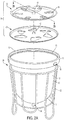
- an exemplary apparatus 10 is used as a countertop composter for collecting and storing organic waste.
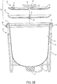
- Apparatus 10 includes a container 12, a frame 20, and a lid 34 including a first lid portion 30 and a second lid portion 40.
- the container 12 has a bottom wall 11, a side wall 13, an open top 15 and a top edge (or rim) 17 of a predetermined size extending inwardly from the side wall 13.
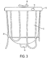
- the frame 20 is configured to be removeably coupled to and support the container 12.
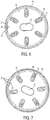
- the first lid portion 30 has at least one venting region 36 defining a one or more holes ( FIG. 4 ).
- the second lid portion 40 defines at least one opening 46 ( FIG. 5 ).
- the first lid portion 30 is configured to be disposed on the second lid portion 40 in pivoting relation.
- the second lid 40 is configured to be disposed on the top edge 17 of the container 12 to cover the container 12.
- the top edge 17 is an inward top edge for receiving the second lid 40.
- the first lid portion may define a concave portion or depression 31 as illustrated in FIG. 4 .
- the first lid portion (or the top lid portion) 30 is configured to be movable relative to the second lid portion (or the bottom lid portion) 40 from a sealed or closed configuration ( FIG. 6 ) to a venting or open configuration ( FIGS. 7-8 ).
- the open and closed configurations are based on alignments observed vertically or in a direction normal to a top surface of the first lid portion 30.
- the closed configuration FIG. 6
- all the venting region 36 of the first lid portion 30 overlap with the second lip portion 40, without overlap with the at least one opening 46.
- the solid base of the second lip portion 40 blocks the venting region 36 of the first lid portion 30.
- the at least one venting region 36 of the first lid portion 30 and the at least one opening 46 of the second lid portion 40 are at least partially overlaps in the venting configuration.
- FIG. 7 illustrates a half (e.g., 50%) open configuration.
- FIG. 8 illustrates a full open configuration. In the full open configuration, the at least one venting region 36 is fully aligned and overlaps with portions of the at least one opening 46.
- FIGS. 6-8 are for illustration only.
- the shaded areas are used to illustrate the overlap between the venting region 36 and the second lid portion 40.
- the material of the second lid portion 40 inside the shaded areas are the same as the material in other portions of the second lid portion 40.
- FIG. 9 is a perspective view of the underside of the second lid 40.
- the first lid 30 with venting regions 36 may be seen depending on the configuration.
- aperture indicators 35, 37 may be debossed into the lid portions.
- the first lid potion 30 may include a pointing indicator 35.
- the second lid portion 40 may contains three position indicators 37. When the pointing indicator 35 points to each position of the three position indicators 37, the lids 30 and 40 are in each of the configurations including closed ( FIG. 6 ), partial open ( FIG. 7 ) and full open ( FIG. 8 ) configurations.
- the pointing indicator 35 may be positioned toward an area between two position indicators 37. In some embodiments, the indicator 35 may be proximate to the concaved portion or depression 31 of the first lid portion 30 so that the indicators are easily seen.
- the second lid portion 40 is also configured to be movable relative to the first lid portion 30. In some embodiments, the rotation angle is limited to a predetermined minimum to a predetermined maximum angle.
- the second lid portion 40 may include a bottom lid tab 48 ( FIG. 9 ), which can be pushed to facilitate separation of the first lid portion 30 from the second lid 40 portion.
- the apparatus 10 may further comprise a knob 50 on the first lid portion 30.
- the knob 50 is shaped and configured to move the first lid portion 30 relative to the second lid portion 40 so as to form a sealed configuration or a venting configuration.
- the knob 50 may comprise or be made of a material of metal, plastic or any combination thereof.
- the knob 50 and the first lid portion 30 may be in a unitary structure molded from a plastic material in a single step. Alternatively, the knob 50 may be made separately and then attached with the first lid portion 30 through any suitable means such as screws, adhesive, or bonding.
- the knob 50 is coupled with a center 32 of the first lid portion 30, and is hollow facing inward. Referring to FIGS.
- the second lid portion 40 has an upward pin 42 shaped and sized to be inserted into the knob 50 through a hole 52 defined by the first lid portion 30 in the center 32.
- the upward pin 42 can have an outside diameter the same as or smaller than the inside diameter of the hole 52. The upward pin 42 can rotate inside the hole 52.
- the container 12 further comprises an outwardly extending rib 16.
- the rib 16 may be made of the same or different material for the container 12.
- the container 12 including the rib 16 are integrally molded from a same elastomer such as silicone.
- the rib 16 has higher rigidity and hardness compared to the main body of the container 12.
- the apparatus 10 further comprises at least one (e.g., three) frame clip 18 embedded in the outwardly extending rib 16 and configured to be coupled with the outwardly extending rib 16 and the frame 20 so as to hold and secure the container 12 to the frame 20.
- the frame clip 18 can be a plastic clip embedded in the rim of the container 12, and having a hook structure, which can be engaged with metal wire of the frame 20.
- the frame clip 18 secures and holds the container 12 onto the frame 20, when the container 12 faces up or down.
- the container 12 may further comprise a tab 14 attached to an outside surface of the bottom wall 11.
- the tab 14 is shaped and sized to be applied to a force and translate to the container 12 so as to push the container 12 inward and pull the container 12 outward, when the apparatus 10 is inverted.
- the tab 14 may be in a unitary structure together with the container 12.
- the container 12 having the tab 14 are molded in one step.
- the container 12 may be in any suitable shape.
- the container 12 may be a bucket substantially in a shape of a cylinder or a frustum of cone.
- the lid including first lid portion 30 and the second lid portion 40, is substantially circular.
- the first lid portion 30 may have a size equal to or smaller than the predetermined size.
- the second lid portion 40 may also have a size equal to or smaller than the predetermined size.
- the first lid portion 30 is slightly smaller than the second lid portion 40, and is shaped to have a bottom surface substantially matching with a top surface of the second lid portion 40.
- the second lid portion 40 may comprise an edge facing downward shaped and sized to be interlocked with the top edge 17 of the container 12 in some embodiments.
- the edge of the second lid portion 40 and the top edge 17 of the container 12 may be configured to form a male-female interlocking structure circumferentially in some embodiments.
- the at least one venting region 36 of the first lid portion 30 can be in any suitable configuration to provide one or more holes or apertures through the first lid portion 30.
- the at least one venting region 36 of the first lid portion 30 may comprise a mesh structure, a grid structure, a net structure, or the like or any combination thereof.
- the at least one venting region 36 may be arranged in a pattern.
- the first lid portion 30 comprises six venting regions 36 radially distributed around the center 32 and throughout the first lid portion 30, as illustrated in FIG. 4 .
- the second lid portion 40 defines six openings 46 radially distributed throughout the second lid portion 40 accordingly.
- the first lid portion 30 with venting regions 36 and the second lid portion 40 with openings 46 are described for illustration only.
- the structures of the first lid portion 30 and the second lid portion 40 can be interchangeable.
- the first lid portion 30 may have the opening 46 as described and the second lid portion 40 may have the venting regions 36 as described.
- the lid includes only a single portion that defines one or more venting regions therethrough.
- a cover can be pivotally or otherwise moveably coupled to the lid and is adapted to cover and uncover the venting region a desired amount.
- One of ordinary skill in the art will understand that other means for providing adjustable venting in the cover can be implemented.
- the container 12 is made of an elastomer, which is optionally reinforced.
- the container 12 may have a smooth or a matted or textured surface. It is preferable that the material for the container 12 has a certain flexibility such that the container 12 is movable when pushed from the bottom 11 with a certain amount of force while the container will substantially maintain its shape when a force below the certain threshold is applied.
- the amount of force required to invert the container should not be greater than an average adult or child can exert.
- the flexibility of the container 12 can be defined based on its Shore A hardness, which may be in the range of from 20 to 90, measured following ASTM D 2240.
- the container is made of a material having a Shore A hardness less than or equal to 80 is preferable. Such a material may have a shore A hardness of any suitable ranges, for example, 20-80, 30-80, 40-80, 50-80, 30-70, 40-70, or any other combination.
- the container 12 is made of an elastomer, preferably a hydrophobic and mold resistant elastomer in some embodiments.
- the container 12 is made of a hydrophobic elastomer having a shore A hardness in the range from 20 to 90 for example, 20-70, 30-70, 40-70, 50-70, 30-60, 40-60) in some embodiments.
- suitable materials include but are not limited to silicone (including fluorosilicone), polyolefin elastomer, nitrile rubber, ethylene propylene diene monomer (EPDM) rubber, and fluoroelastomer.
- the container 12 including the tab 14 is made of silicone.
- the lid including the first lid portion 30, knob 50, and the second lid portion 40, may be made of a plastic or reinforced elastomer.
- Suitable materials for the lid may be a plastic or reinforced elastomer material having a Shore D hardness in the range from 10-90 (e.g., 30-80, 30-70, 30-60, 40-80, 40-70, 40-60, or any suitable ranges or combinations thereof), measured following ASTM D2240.
- such a material may be a reinforced elastomer material having a Shore A hardness in the range from 70-90, measured following ASTM D2240.
- Such suitable materials may be a hydrophobic and/or mold resistant.
- suitable materials include but are not limited to high density polyethylene (HDPE), low density polyethylene (LDPE), polypropylenene (PP), acrylonitrile butadiene styrene (ABS) polymer, other polyolefins, polyethylene terephthalate (PET), polybutylene terephthalate (PBT), polyamide such as nylon, polycarbonate, polysulfone, reinforced elastomer such as silicone or polyolefin elastomer, or any combination thereof.
- the materials for the lid including top lid portion 30, the bottom lid portion 40, and knob 50, also have good strength and toughness.
- knob 50 is injected molded with plastics in a single process and then attached with the first lid portion 30 as described.
- Frame clip 18 is made of plastic and has higher rigidity and hardness compared to the container.
- suitable materials for frame clip 18 include but are not limited to high density polyethylene (HDPE), low density polyethylene (LDPE), polypropylenene (PP), acrylonitrile butadiene styrene (ABS) polymer, other polyolefins, polyethylene terephthalate (PET), polybutylene terephthalate (PBT), polyamide such as nylon, polycarbonate, polysulfone, reinforced elastomer such as silicone or polyolefin elastomer, or any combination thereof.
- frame clip 18 is made of nylon, which is molded into silicone for rib 16 and container 12. The frame clips 18 may be in a color different from that of rib 16.
- the frame 20 may be made of a metal, a plastics or a combination thereof.
- the frame 20 is made of metal wires such as stainless steel wires.
- the frame 20 may include an internal structure to at least partially support the bottom 11 of the container 12. The frame may have a polished and smooth surface.
- the present disclosure provides a method of making the exemplary apparatus 10 as described.
- Such a method comprises the steps of providing the container 12, the frame 20, the lid 34, which may include the first lid portion 30 and the second lid portion 40; and assembling the container 12, the frame 20, the first lid portion 30 and the second lid portion 40 to form the apparatus 10.
- the container 12 including the bottom tab 14 and the outwardly extending rib 16 may be molded from a same material such as an elastomer or different materials, as described.
- the container 12 including the bottom tab 14 and the outwardly extending rib 16 may be in a unitary structure.
- the first lid portion 30 or the second lid portion 40 may be molded from a plastic or reinforced elastomer.
- the knob 50 and the first lid portion 40 may be in a unitary structure molded in a single step. Alternatively, the knob 50 may be made separately and then attached with the lid through any suitable means such as screws or bonding.
- the upward pin 42 and the second lid portion 40 may be in a unitary structure molded in a single step.
- the container 12 is coupled onto the frame 20, for example, by pushing the frame clip 18 inward and coupling with the frame 20.
- the second lid portion 40 is placed onto the top edge 17 of the container 12 so as to cover the container 12.
- the second lid portion 40 may have an edge to engage or interlock with the top edge 17 of the container 12.
- the first lid portion 30 is placed onto the second lid portion 40.
- the present disclosure also provides a method of using the apparatus 10 as described.
- the apparatus 10 is placed on a countertop in a kitchen.
- the lid e.g., the first and the second lid portions 30, 40
- Organic waste such as peeling, vegetables and food leftovers, can be placed into the container 12.
- the first lid portion 30 is moved relative to the second lid portion 40 to one of the sealed configuration and the venting configuration so as to adjust airflow into the container 12. It is preferable that a certain amount of air may get into the container 12 for compositing, but no odor of decayed waste comes out of the container 12.
- the first lid 30 comprises a knob 50 as described.
- the first lid portion 30 is moved relative to the second lid portion 40 by applying a force to the knob 50 to rotate the first lid portion 30 relative to the second lid portion 40.
- the method of using may further comprise removing the lid (i.e., first and the second lid portions 30, 40) from the container 12, inverting the container 12 (not shown) with the open top at least partially facing down, and pushing the container 12 so as to remove the organic wastes out of the container 12.
- the container 12 remains attached with the frame 20, the container 12 maintains its shape without collapsing.
- FIGS. 10-12 illustrate an exemplary process for inverting and pushing the apparatus 10. Referring to FIG. 10 , the apparatus 10 is turned upside down.
- the container 12 comprises a tab 14 as described on an outside surface of the bottom wall. Referring to FIG. 11 , the container 12 can be pushed inward by pushing the tab 14 down.
- the container 12 can be further pushed fully inside out to be in a configuration as illustrated in FIG. 12 .
- the interior wall of the container 12 is exposed outside. The waster can be discarded, and the container 12 can be then washed.
- the organic waste may be kept in the container 12 for a period of time from one day to a month. For example, the organic waste in the container 12 may be discarded out once a week.
- the tab 14 is pushed to discard the organic wastes inside the container 12.
- the tab 14 is pulled, i.e., a force is applied onto the tab 14, to translate the container 12 such that the container 12 reverts back to a waste-receiving configuration as shown in FIG. 1
- the container 12 can be washed or rinsed with water under a faucet or with water from a garden hose.
- the container 12 can be also detached from frame 20 and washed in a dishwasher. After being cleaned, the components can be re-assembled for further use.
Landscapes
- Engineering & Computer Science (AREA)
- Chemical & Material Sciences (AREA)
- Mechanical Engineering (AREA)
- Organic Chemistry (AREA)
- Chemical Kinetics & Catalysis (AREA)
- Biotechnology (AREA)
- Health & Medical Sciences (AREA)
- General Chemical & Material Sciences (AREA)
- Microbiology (AREA)
- Molecular Biology (AREA)
- Biochemistry (AREA)
- Life Sciences & Earth Sciences (AREA)
- Manufacturing & Machinery (AREA)
- Closures For Containers (AREA)
Applications Claiming Priority (1)
| Application Number | Priority Date | Filing Date | Title |
|---|---|---|---|
| US201762472780P | 2017-03-17 | 2017-03-17 |
Publications (1)
| Publication Number | Publication Date |
|---|---|
| EP3375768A1 true EP3375768A1 (fr) | 2018-09-19 |
Family
ID=61691709
Family Applications (1)
| Application Number | Title | Priority Date | Filing Date |
|---|---|---|---|
| EP18162418.0A Withdrawn EP3375768A1 (fr) | 2017-03-17 | 2018-03-16 | Appareil de compostage, procédé de fabrication et son procédé d'utilisation |
Country Status (2)
| Country | Link |
|---|---|
| US (1) | US20180265421A1 (fr) |
| EP (1) | EP3375768A1 (fr) |
Families Citing this family (1)
| Publication number | Priority date | Publication date | Assignee | Title |
|---|---|---|---|---|
| USD891719S1 (en) * | 2019-07-15 | 2020-07-28 | Petina Sponder | Compost bin |
Citations (6)
| Publication number | Priority date | Publication date | Assignee | Title |
|---|---|---|---|---|
| DE2707568B1 (de) * | 1977-02-22 | 1977-11-24 | Brigitte Schuhmann | Komposter für garten und gemüseabfälle |
| AU7528387A (en) * | 1986-07-09 | 1988-01-14 | Smiths Industries Precision Fan Co. Pty. Ltd. | Collapsible container |
| NL9200512A (nl) * | 1992-03-19 | 1993-10-18 | Vam Nv | Vat voor het bereiden van compost. |
| WO1994029240A1 (fr) * | 1993-06-03 | 1994-12-22 | Ecora Oy Tara Finland Ltd. | Bac de compost |
| WO2008047135A1 (fr) * | 2006-10-18 | 2008-04-24 | Invicta Plastics Limited | Kit d'essai de biodégradabilité |
| EP2933208A1 (fr) * | 2014-04-17 | 2015-10-21 | Conscia AB | Réceptacle à déchets réutilisable et procédé pour son vidage |
Family Cites Families (11)
| Publication number | Priority date | Publication date | Assignee | Title |
|---|---|---|---|---|
| US4687645A (en) * | 1982-09-29 | 1987-08-18 | Harvey Christian D | Composting unit |
| GB2169813B (en) * | 1984-12-19 | 1988-06-02 | Blackwall Products Limited | Compost-making apparatus and method |
| CA2077183C (fr) * | 1992-08-28 | 1996-01-16 | Narayan Raghunathan | Composteurs menagers |
| US5395006A (en) * | 1993-04-29 | 1995-03-07 | Verma; Kuldeep | Fermentation vessels and closures therefor |
| US6264359B1 (en) * | 1997-07-22 | 2001-07-24 | America's Gardening Resource, Inc. | Rotatable composter |
| US6245557B1 (en) * | 1999-06-30 | 2001-06-12 | Robert P. Fouts | Cell and protein harvesting assemblies and methods |
| US8129177B2 (en) * | 2006-08-08 | 2012-03-06 | Nature Mill, Inc. | Composting systems and methods |
| AT507225B1 (de) * | 2008-08-29 | 2011-03-15 | Wuester Heinrich | Frühbeetverbindung |
| US20120021504A1 (en) * | 2010-07-20 | 2012-01-26 | Michael Bradlee | Aerated composter and waste collection bin |
| US9216855B2 (en) * | 2013-05-17 | 2015-12-22 | Rehrig Pacific Company | Vented lid for cart |
| CN108699502A (zh) * | 2016-02-23 | 2018-10-23 | 康宁股份有限公司 | 灌注生物反应器及其用于进行连续细胞培养的方法 |
-
2018
- 2018-03-16 EP EP18162418.0A patent/EP3375768A1/fr not_active Withdrawn
- 2018-03-16 US US15/923,021 patent/US20180265421A1/en not_active Abandoned
Patent Citations (6)
| Publication number | Priority date | Publication date | Assignee | Title |
|---|---|---|---|---|
| DE2707568B1 (de) * | 1977-02-22 | 1977-11-24 | Brigitte Schuhmann | Komposter für garten und gemüseabfälle |
| AU7528387A (en) * | 1986-07-09 | 1988-01-14 | Smiths Industries Precision Fan Co. Pty. Ltd. | Collapsible container |
| NL9200512A (nl) * | 1992-03-19 | 1993-10-18 | Vam Nv | Vat voor het bereiden van compost. |
| WO1994029240A1 (fr) * | 1993-06-03 | 1994-12-22 | Ecora Oy Tara Finland Ltd. | Bac de compost |
| WO2008047135A1 (fr) * | 2006-10-18 | 2008-04-24 | Invicta Plastics Limited | Kit d'essai de biodégradabilité |
| EP2933208A1 (fr) * | 2014-04-17 | 2015-10-21 | Conscia AB | Réceptacle à déchets réutilisable et procédé pour son vidage |
Non-Patent Citations (1)
| Title |
|---|
| DATABASE WPI Week 199345, Derwent World Patents Index; AN 1993-357943, XP002783073 * |
Also Published As
| Publication number | Publication date |
|---|---|
| US20180265421A1 (en) | 2018-09-20 |
Similar Documents
| Publication | Publication Date | Title |
|---|---|---|
| US9752306B2 (en) | Waste strainer | |
| US12338065B2 (en) | Waste receptacles | |
| US20220047121A1 (en) | Disposable container for use in a sink | |
| US20100193534A1 (en) | Compost collection bin | |
| RU2011129301A (ru) | Крышечная часть для емкости | |
| EP3375768A1 (fr) | Appareil de compostage, procédé de fabrication et son procédé d'utilisation | |
| US20120223078A1 (en) | Compost material collector | |
| CN203255589U (zh) | 一种能保持干燥的垃圾桶 | |
| KR101737226B1 (ko) | 악취의 새어나옴과 음식물쓰레기에서 발생된 오수의 배출이 용이한 가정용 음식물쓰레기통 | |
| US20130313378A1 (en) | Bag Holder and Waste Bin Incorporating Snaps to Lock Bag Open | |
| KR200367280Y1 (ko) | 탈수 기능을 갖는 음식물 쓰레기통 | |
| KR101418740B1 (ko) | 음식물쓰레기 수집 시스템 | |
| CN113891844B (zh) | 沥水垃圾袋的保持用具 | |
| KR101179765B1 (ko) | 음식물 쓰레기 처리물 건조용 통풍유도체 | |
| KR20190000796U (ko) | 휴대용 쓰레기 수거기 | |
| KR101232280B1 (ko) | 음식물쓰레기통 | |
| CN108557345A (zh) | 一种家用多功能分类垃圾桶 | |
| CN201082815Y (zh) | 家用分类垃圾桶 | |
| CN208453686U (zh) | 一种分层收集的环保垃圾桶 | |
| KR100904273B1 (ko) | 싱크대의 배수/배출 장치 | |
| JP2002322704A (ja) | 排水口のごみ漉しネット装着用プレートおよびごみ漉し具 | |
| CN211253825U (zh) | 一种便携式分类垃圾桶 | |
| CN2683593Y (zh) | 固体液体分离式垃圾桶 | |
| JPH0750463Y2 (ja) | 雨水ます用防臭装置 | |
| KR101955400B1 (ko) | 쓰레기통 |
Legal Events
| Date | Code | Title | Description |
|---|---|---|---|
| PUAI | Public reference made under article 153(3) epc to a published international application that has entered the european phase |
Free format text: ORIGINAL CODE: 0009012 |
|
| STAA | Information on the status of an ep patent application or granted ep patent |
Free format text: STATUS: THE APPLICATION HAS BEEN PUBLISHED |
|
| AK | Designated contracting states |
Kind code of ref document: A1 Designated state(s): AL AT BE BG CH CY CZ DE DK EE ES FI FR GB GR HR HU IE IS IT LI LT LU LV MC MK MT NL NO PL PT RO RS SE SI SK SM TR |
|
| AX | Request for extension of the european patent |
Extension state: BA ME |
|
| STAA | Information on the status of an ep patent application or granted ep patent |
Free format text: STATUS: REQUEST FOR EXAMINATION WAS MADE |
|
| 17P | Request for examination filed |
Effective date: 20190315 |
|
| RBV | Designated contracting states (corrected) |
Designated state(s): AL AT BE BG CH CY CZ DE DK EE ES FI FR GB GR HR HU IE IS IT LI LT LU LV MC MK MT NL NO PL PT RO RS SE SI SK SM TR |
|
| STAA | Information on the status of an ep patent application or granted ep patent |
Free format text: STATUS: EXAMINATION IS IN PROGRESS |
|
| 17Q | First examination report despatched |
Effective date: 20200904 |
|
| STAA | Information on the status of an ep patent application or granted ep patent |
Free format text: STATUS: THE APPLICATION IS DEEMED TO BE WITHDRAWN |
|
| 18D | Application deemed to be withdrawn |
Effective date: 20210115 |