EP3375957A1 - Dispositif de blocage - Google Patents
Dispositif de blocage Download PDFInfo
- Publication number
- EP3375957A1 EP3375957A1 EP17161677.4A EP17161677A EP3375957A1 EP 3375957 A1 EP3375957 A1 EP 3375957A1 EP 17161677 A EP17161677 A EP 17161677A EP 3375957 A1 EP3375957 A1 EP 3375957A1
- Authority
- EP
- European Patent Office
- Prior art keywords
- locking device
- electric drive
- locking
- locking element
- actuator
- Prior art date
- Legal status (The legal status is an assumption and is not a legal conclusion. Google has not performed a legal analysis and makes no representation as to the accuracy of the status listed.)
- Granted
Links
Images

Classifications
-
- E—FIXED CONSTRUCTIONS
- E05—LOCKS; KEYS; WINDOW OR DOOR FITTINGS; SAFES
- E05B—LOCKS; ACCESSORIES THEREFOR; HANDCUFFS
- E05B47/00—Operating or controlling locks or other fastening devices by electric or magnetic means
- E05B47/0001—Operating or controlling locks or other fastening devices by electric or magnetic means with electric actuators; Constructional features thereof
- E05B47/0012—Operating or controlling locks or other fastening devices by electric or magnetic means with electric actuators; Constructional features thereof with rotary electromotors
-
- E—FIXED CONSTRUCTIONS
- E05—LOCKS; KEYS; WINDOW OR DOOR FITTINGS; SAFES
- E05B—LOCKS; ACCESSORIES THEREFOR; HANDCUFFS
- E05B47/00—Operating or controlling locks or other fastening devices by electric or magnetic means
- E05B47/02—Movement of the bolt by electromagnetic means; Adaptation of locks, latches, or parts thereof, for movement of the bolt by electromagnetic means
- E05B47/026—Movement of the bolt by electromagnetic means; Adaptation of locks, latches, or parts thereof, for movement of the bolt by electromagnetic means the bolt moving rectilinearly
-
- E—FIXED CONSTRUCTIONS
- E05—LOCKS; KEYS; WINDOW OR DOOR FITTINGS; SAFES
- E05B—LOCKS; ACCESSORIES THEREFOR; HANDCUFFS
- E05B65/00—Locks or fastenings for special use
- E05B65/10—Locks or fastenings for special use for panic or emergency doors
-
- E—FIXED CONSTRUCTIONS
- E05—LOCKS; KEYS; WINDOW OR DOOR FITTINGS; SAFES
- E05C—BOLTS OR FASTENING DEVICES FOR WINGS, SPECIALLY FOR DOORS OR WINDOWS
- E05C1/00—Fastening devices with bolts moving rectilinearly
- E05C1/002—Fastening devices with bolts moving rectilinearly perpendicular to the surface on which the fastener is mounted
-
- E—FIXED CONSTRUCTIONS
- E05—LOCKS; KEYS; WINDOW OR DOOR FITTINGS; SAFES
- E05C—BOLTS OR FASTENING DEVICES FOR WINGS, SPECIALLY FOR DOORS OR WINDOWS
- E05C1/00—Fastening devices with bolts moving rectilinearly
- E05C1/08—Fastening devices with bolts moving rectilinearly with latching action
-
- G—PHYSICS
- G06—COMPUTING OR CALCULATING; COUNTING
- G06K—GRAPHICAL DATA READING; PRESENTATION OF DATA; RECORD CARRIERS; HANDLING RECORD CARRIERS
- G06K7/00—Methods or arrangements for sensing record carriers, e.g. for reading patterns
- G06K7/10—Methods or arrangements for sensing record carriers, e.g. for reading patterns by electromagnetic radiation, e.g. optical sensing; by corpuscular radiation
- G06K7/10009—Methods or arrangements for sensing record carriers, e.g. for reading patterns by electromagnetic radiation, e.g. optical sensing; by corpuscular radiation sensing by radiation using wavelengths larger than 0.1 mm, e.g. radio-waves or microwaves
- G06K7/10366—Methods or arrangements for sensing record carriers, e.g. for reading patterns by electromagnetic radiation, e.g. optical sensing; by corpuscular radiation sensing by radiation using wavelengths larger than 0.1 mm, e.g. radio-waves or microwaves the interrogation device being adapted for miscellaneous applications
-
- E—FIXED CONSTRUCTIONS
- E05—LOCKS; KEYS; WINDOW OR DOOR FITTINGS; SAFES
- E05B—LOCKS; ACCESSORIES THEREFOR; HANDCUFFS
- E05B15/00—Other details of locks; Parts for engagement by bolts of fastening devices
- E05B15/02—Striking-plates; Keepers; Bolt staples; Escutcheons
- E05B15/0205—Striking-plates, keepers, staples
- E05B2015/023—Keeper shape
-
- E—FIXED CONSTRUCTIONS
- E05—LOCKS; KEYS; WINDOW OR DOOR FITTINGS; SAFES
- E05B—LOCKS; ACCESSORIES THEREFOR; HANDCUFFS
- E05B47/00—Operating or controlling locks or other fastening devices by electric or magnetic means
- E05B47/0001—Operating or controlling locks or other fastening devices by electric or magnetic means with electric actuators; Constructional features thereof
- E05B2047/0014—Constructional features of actuators or power transmissions therefor
- E05B2047/0015—Output elements of actuators
- E05B2047/0017—Output elements of actuators with rotary motion
-
- E—FIXED CONSTRUCTIONS
- E05—LOCKS; KEYS; WINDOW OR DOOR FITTINGS; SAFES
- E05B—LOCKS; ACCESSORIES THEREFOR; HANDCUFFS
- E05B47/00—Operating or controlling locks or other fastening devices by electric or magnetic means
- E05B47/0001—Operating or controlling locks or other fastening devices by electric or magnetic means with electric actuators; Constructional features thereof
- E05B2047/0014—Constructional features of actuators or power transmissions therefor
- E05B2047/0018—Details of actuator transmissions
- E05B2047/002—Geared transmissions
- E05B2047/0022—Planetary gears
-
- E—FIXED CONSTRUCTIONS
- E05—LOCKS; KEYS; WINDOW OR DOOR FITTINGS; SAFES
- E05B—LOCKS; ACCESSORIES THEREFOR; HANDCUFFS
- E05B47/00—Operating or controlling locks or other fastening devices by electric or magnetic means
- E05B47/0001—Operating or controlling locks or other fastening devices by electric or magnetic means with electric actuators; Constructional features thereof
- E05B2047/0014—Constructional features of actuators or power transmissions therefor
- E05B2047/0018—Details of actuator transmissions
- E05B2047/0023—Nuts or nut-like elements moving along a driven threaded axle
-
- E—FIXED CONSTRUCTIONS
- E05—LOCKS; KEYS; WINDOW OR DOOR FITTINGS; SAFES
- E05B—LOCKS; ACCESSORIES THEREFOR; HANDCUFFS
- E05B47/00—Operating or controlling locks or other fastening devices by electric or magnetic means
- E05B47/0001—Operating or controlling locks or other fastening devices by electric or magnetic means with electric actuators; Constructional features thereof
- E05B2047/0014—Constructional features of actuators or power transmissions therefor
- E05B2047/0036—Reversible actuators
-
- E—FIXED CONSTRUCTIONS
- E05—LOCKS; KEYS; WINDOW OR DOOR FITTINGS; SAFES
- E05B—LOCKS; ACCESSORIES THEREFOR; HANDCUFFS
- E05B47/00—Operating or controlling locks or other fastening devices by electric or magnetic means
- E05B2047/0048—Circuits, feeding, monitoring
- E05B2047/0067—Monitoring
- E05B2047/0069—Monitoring bolt position
-
- E—FIXED CONSTRUCTIONS
- E05—LOCKS; KEYS; WINDOW OR DOOR FITTINGS; SAFES
- E05B—LOCKS; ACCESSORIES THEREFOR; HANDCUFFS
- E05B47/00—Operating or controlling locks or other fastening devices by electric or magnetic means
- E05B2047/0072—Operation
- E05B2047/0081—Same pulse to lock or unlock
-
- E—FIXED CONSTRUCTIONS
- E05—LOCKS; KEYS; WINDOW OR DOOR FITTINGS; SAFES
- E05B—LOCKS; ACCESSORIES THEREFOR; HANDCUFFS
- E05B47/00—Operating or controlling locks or other fastening devices by electric or magnetic means
- E05B2047/0084—Key or electric means; Emergency release
- E05B2047/0086—Emergency release, e.g. key or electromagnet
-
- E—FIXED CONSTRUCTIONS
- E05—LOCKS; KEYS; WINDOW OR DOOR FITTINGS; SAFES
- E05B—LOCKS; ACCESSORIES THEREFOR; HANDCUFFS
- E05B65/00—Locks or fastenings for special use
-
- E—FIXED CONSTRUCTIONS
- E05—LOCKS; KEYS; WINDOW OR DOOR FITTINGS; SAFES
- E05Y—INDEXING SCHEME ASSOCIATED WITH SUBCLASSES E05D AND E05F, RELATING TO CONSTRUCTION ELEMENTS, ELECTRIC CONTROL, POWER SUPPLY, POWER SIGNAL OR TRANSMISSION, USER INTERFACES, MOUNTING OR COUPLING, DETAILS, ACCESSORIES, AUXILIARY OPERATIONS NOT OTHERWISE PROVIDED FOR, APPLICATION THEREOF
- E05Y2201/00—Constructional elements; Accessories therefor
- E05Y2201/40—Motors; Magnets; Springs; Weights; Accessories therefor
- E05Y2201/43—Motors
- E05Y2201/434—Electromotors; Details thereof
-
- E—FIXED CONSTRUCTIONS
- E05—LOCKS; KEYS; WINDOW OR DOOR FITTINGS; SAFES
- E05Y—INDEXING SCHEME ASSOCIATED WITH SUBCLASSES E05D AND E05F, RELATING TO CONSTRUCTION ELEMENTS, ELECTRIC CONTROL, POWER SUPPLY, POWER SIGNAL OR TRANSMISSION, USER INTERFACES, MOUNTING OR COUPLING, DETAILS, ACCESSORIES, AUXILIARY OPERATIONS NOT OTHERWISE PROVIDED FOR, APPLICATION THEREOF
- E05Y2201/00—Constructional elements; Accessories therefor
- E05Y2201/60—Suspension or transmission members; Accessories therefor
- E05Y2201/622—Suspension or transmission members elements
- E05Y2201/71—Toothed gearing
- E05Y2201/72—Planetary gearing
-
- E—FIXED CONSTRUCTIONS
- E05—LOCKS; KEYS; WINDOW OR DOOR FITTINGS; SAFES
- E05Y—INDEXING SCHEME ASSOCIATED WITH SUBCLASSES E05D AND E05F, RELATING TO CONSTRUCTION ELEMENTS, ELECTRIC CONTROL, POWER SUPPLY, POWER SIGNAL OR TRANSMISSION, USER INTERFACES, MOUNTING OR COUPLING, DETAILS, ACCESSORIES, AUXILIARY OPERATIONS NOT OTHERWISE PROVIDED FOR, APPLICATION THEREOF
- E05Y2900/00—Application of doors, windows, wings or fittings thereof
- E05Y2900/10—Application of doors, windows, wings or fittings thereof for buildings or parts thereof
- E05Y2900/13—Type of wing
- E05Y2900/132—Doors
Definitions
- the invention relates to a locking device according to the preamble of claim 1.
- safety switches are known to be used to secure access to hazardous areas.
- a safety switch a lock of a safety door can be secured as access to a danger area.
- the operation of a hazardous installation within the danger zone is only enabled by a safety controller if the safety door is locked with the safety switch.
- the safety switch here is assigned an actuator.
- the actuator can typically be arranged on the protective door, while the safety switch is arranged on a frame delimiting the door opening.
- the actuator is brought into engagement with the safety switch, for example, by the actuator is retracted into a recess.
- This lock is controlled by detecting a transponder in the actuator with an RFID reader in the safety switch.
- a guard locking of the protective door may be provided.
- a tumbler is for example from the WO 2016/058718 A1 known.
- a Zuhaltebolzen is provided which is actuated by means of an electric motor with a planetary gear. With the electric drive the Zuhaltebolzen can be moved into a blocking position in which the actuator is locked with the Zuhaltebolzen.
- the invention has for its object to provide a locking device of the type mentioned, which has a high functionality.
- the invention relates to an actuatable by means of an electric drive locking element.
- the locking element can be introduced in such a blocking position that an actuator of a safety switch is locked with this.
- the tumbler element is connected to the electric drive via a coupling so that a rotational movement of the electric drive is converted into a pure translational movement of the tumbler element.
- an essential aspect of the invention is that with the coupling and preferably a spindle nut on a driven by the electric drive spindle, a conversion of the rotational movement of the electrical Anriebs is converted into a pure translational movement of the locking element.
- a bistable tumbler is feasible.
- the locking element By means of the electric drive, the locking element can be inserted into the locking position. In this, the locking element engages in a recording of the actuator whereby the tumbler is effected.
- the locking element By means of the electric drive, the locking element can be extended again from the locked position.
- the movement control of the tumbler is complete via the electric drive.
- the locking element In order to be able to hold the actuator with the locking element, the locking element is moved in advance into its release position by means of the electric drive, so that the actuator can be introduced unhindered with its inclusion in the region of the locking element. Then, the locking element is moved by means of the electric drive in the blocking position, whereby the tumbler is realized.
- this decoupling means by means of which the locking element is decoupled from the electric drive against a spring force from the locking position out movable.
- the locking device which can be used for an escape release such that when the locking device, for example, a guard is locked, which blocks access to a danger zone, a person who resides in the danger zone, the Manually unlock the safety door to be able to move out of the danger zone.
- the mechanical unlocking can also be actuated from the outside of the protective door, that is to say by a person outside the danger zone, in order to carry out an auxiliary unlocking in an inspection area of the respective safety device or an emergency unlocking of the protective door.
- the decoupling means are used to realize a catching function.
- the catch function is realized in that by means of an engagement element of the actuator, the tumbler is moved mechanically and decoupled from the electric drive from a blocking position. If the recording of the actuator is in the region of the tumbler element, this is moved back by the spring force in the blocking position and engages in the receptacle of the actuator.
- This catch function is an alternative to bistable tumbler.
- the movement of the tumbler element is not completely controlled by the electric drive in the catch function. Rather, the decoupling means are shared for mechanical decoupling.
- the locking device is operable either with a bistable tumbler or a catch function.
- the functionality of the bistable tumbler or the catching function is defined by a software version of the locking device or can be predetermined by a programming command.
- the clutch has a transverse pin and a cylinder pin extending transversely thereto, wherein the transverse pin is guided in a longitudinal guide and wherein the cylindrical pin secures the transverse pin.
- the thus formed coupling has a very simple structure with few parts.
- the longitudinal axes of the transverse pin and the cylindrical pin extend transversely to the longitudinal axis of the locking element, wherein the transverse pin is mounted with play in a recess of the locking element and wherein the cylinder pin is mounted with clearance in a recess of the transverse pin.
- the tumbler according to the invention is insensitive to unavoidable component tolerances, whereby the reliability of the locking device is increased.
- the electric drive has an electric motor with a planetary gear.
- a spindle is provided on the electric drive, which carries out a feed movement by the rotational movement of the electric drive, which is converted to a coupled by means of a spindle nut to the spindle driver, which is coupled via the coupling with the locking element.
- the driver is connected by means of the cylindrical pin with the clutch and thus stored against infeed.
- the locking device formed in this way has a compact, robust construction.
- the driver is formed as a hollow cylinder, wherein the interior of the driver forms a decoupling path as part of the decoupling means, wherein the spindle along the decoupling path is feasible.
- a spring force-generating spring is mounted between the driver and the decoupling means.
- a cable is guided within the tumbler element, wherein on the tumbler element a cable deflection is arranged, by means of which the cable is positively guided along a trajectory.
- the cable is connected to a built-in Zuhalteelement sensor means for controlling the tumbler.
- the opening at the cable deflection cable is guided laterally next to the components of the locking device.
- the locking element in a release position corresponding lower end position can be introduced, which is controllable by means of a sensor.
- the locking element can be introduced into a release position corresponding lower end position, which is controllable by means of a sensor. This determines the lower position of the spindle nut. Based on this, the other positions of the spindle nut are determined by means of a rotary encoder of the electric drive.
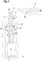
- FIG. 1 shows an embodiment of the locking device according to the invention 1.
- the locking device 1 is used to lock an actuator 2, which is part of a safety device with a safety switch, not shown.
- the actuator 2 can be arranged on the safety door
- the safety switch can be arranged on a frame delimiting the door opening, which is closed with the safety door.
- the closed position of a protective door is controlled by an RFID reader in the safety switch reading the coded signal of a transponder in the actuator.
- the locking device 1 has a housing 3 for receiving its individual components.
- a locking element 4 which is formed in the present case by a Zuhaltebolzen be extended over an opening at the top of the housing 3 and retracted into a recess 5 on the underside of the actuator 2.
- an electric drive 6 is mounted, which has an electric motor with a planetary gear.
- the current rotational position of the electric motor is detected by a rotary encoder 7.
- a spindle 8 is driven.
- the front end of the spindle 8 is connected to a driver 9.
- the driver 9 is formed as a hollow cylinder.
- the front end of the spindle 8 projects beyond the underside of the driver 9 in its interior and is supported there by means of a spindle nut 10.
- the locking element 4 is coupled by means of a coupling 11 to the upper end of the driver 9.
- a rotational movement of the driven by the electric drive 6 spindle 8 is converted by the clutch 11 and the spindle nut 10 in a pure translational movement of the locking element 4.
- This coupling 11 has a transverse pin 12 and a cylindrical pin 13, whose longitudinal axes are oriented perpendicular to each other and each perpendicular to the longitudinal axis of the driver 9 and the hollow cylindrical locking element 4.
- the longitudinal axes of the spindle 8, the driver 9 and the locking element 4 extend along the axes of symmetry of the housing third
- the transverse pin 12 is guided in a longitudinal guide 14 in the form of a slot in the housing 3.
- the longitudinal axis of the slot extends in the longitudinal direction of the housing third
- the cylinder pin 13 lies with play in a recess 16 of the transverse pin 12 and further in recesses 17a, 17b in the wall of the driver 9, whereby the transverse pin 12th is secured.
- coupling 11 takes place in the axial direction, a torsionally rigid and play-free coupling of the locking element 4 to the spindle 8 and thus to the electric drive 6, so that 6 exact strokes of the locking element 4 can be performed by means of the electric drive.
- By guiding the transverse pin 12 in the longitudinal guide 14 ensures that the rotational movement of the electric drive 6 is converted into a pure translational movement of the driver 9 and thus the locking element 4.
- a spring 18 is disposed between the underside of the driver 9 and the top of the electric drive 6, with which a spring force extending in the axial direction is generated.
- FIGS. 1 and 3 show the locking element 4 in its blocking position in which this is extended beyond the top of the housing 3 addition.
- the necessary adjustment movement is effected with the electric drive 6.
- the upper end of the spindle 8 lies with the spindle nut 10 in the lower region of the interior of the hollow cylindrical driver 9.
- This interior forms a decoupling path and thus a decoupling means for the locking element 4.
- a mechanical unlocking of the locking element 4, decoupled from the electric drive 6, allows.
- the tumbler element 4 can namely from its locked position into its release position, in which the tumbler 4 is fully retracted into the housing 3, purely mechanical and decoupled from the electric drive 6 are attached, since when exerting a compressive force from above on the tumbler 4, the spindle nut 10 can move along the decoupling path.
- the locking element 4 is transferred independently of the electric drive 6 and against the spring force of the spring 18 from the locking position to the release position. This can be used for an escape release of the locking device 1.
- a sensor means 19 is located in the actuator 2. If the tumbler element 4 is retracted to the tumbler of the actuator 2 in the recess 5 of the actuator 2, generate the sensor means 19, 20 a corresponding signal. Thus, the tumbler is controlled with these sensor means 19, 20.
- the sensor means 19, 20 may be formed for example by a proximity switch or an RFID system.
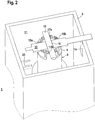
- the sensor means 19 is connected via a cable 21 to an electronics on the electric drive 6.
- the cable 21 extends from the sensor means 19, starting in the interior of the locking element 4 in the vertical direction. Then the cable 21 is guided in a cable guide 22.
- the cable guide 22 forms a positive guide for the cable 21 such that it is deflected twice by 90 °. It is essential here that the cable 21 is deflected in the cable guide 22 in relatively large radii of curvature and thereby positively constrained, so that a kinking or other damage to the cable 21 is avoided.
- the emerging at the cable guide 22 cable 21 then runs in the vertical direction to the electronics and is connected there. It is essential here that the cable 21 extends at a distance from the components of the locking device 1, so that a kinking or pinching of the cable 21 is avoided even with a movement of the locking element 4.
- the locking element 4 can be moved by means of the electric drive 6 between the locking position and the release position, which may be predetermined by end stops, not shown.
- the adjusting movements of the locking element 4 are sensor-controlled.
- a suitable sensor system is advantageously provided for this purpose, which in the simplest case can be formed by a single sensor element 23. With the sensor element 23, the lower end position of the locking element 4 is detected. If the spindle nut 10 is moved into its lower end position, this is determined indirectly with the sensor element 23 by detecting the lower end position of the locking element 4. This lower end position serves as a reference position. Based on this, the relative positions of the spindle nut 10 relative to the reference position are detected with the rotary encoder 7 of the electric drive 6. Thus, only a single sensor element 23 is required in the locking device 1.
- a bistable tumbler as well as a catch function for carrying out a tumbler realized become.
- the locking device 1 can optionally be operated with a bistable tumble or a catch function.
- the selection can be made by the manufacturer by means of a suitable software variant. Alternatively, the selection can be made by entering a programming command of an authorized person in the control of the locking device 1.
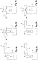
- FIGS. 4 a - c show the sequence of a bistable tumbler which is completely controlled by the electric drive 6.
- the actuator 2 at its front end as an engagement element on an inclined surface 2a. This engagement element is not needed in the bistable tumbler.
- FIG. 4a shows the initial state when the actuator 2 is not yet in the area of the locking device 1.
- the locking element 4 is retracted by means of the electric drive 6 in its release position, so that the locking element can be completely retracted into the housing 3 of the locking device 1.
- the actuator 2 can now be introduced by pivoting or moving the guard in the area of the locking device 1, which is the case when the guard is in its closed position and the actuator 2 is locked in the safety switch. This is in FIG. 4b shown.
- the actuator 2 can be extended by means of the electric drive 6 in its blocking position so that it projects into the receptacle of the actuator 2 ( Figure 4c ), whereby the tumbler of the actuator 2 is effected.
- the tumbler can then be released again by means of the electric drive 6, the tumbler element 4 is transferred to the release position.
- FIGS. 5a-5c show the procedure for the catch function.
- the actuator 2 is retracted into the region of the locking device 1, the actuator 2 is guided with the inclined surface 2a against the locking element 4 ( FIG. 5b ).
- the locking element 4 can move downwards, that is, the mechanical force exerted by the actuator 2 on the inclined surface 2a, the locking element 4 is decoupled from the electric drive 6 and against the spring force of the spring 18 down to the release position pressed.
- the locking element 4 is transferred by means of the electric drive 6 in the release position.
Landscapes
- Physics & Mathematics (AREA)
- Engineering & Computer Science (AREA)
- Electromagnetism (AREA)
- Mechanical Engineering (AREA)
- Health & Medical Sciences (AREA)
- Toxicology (AREA)
- Computer Vision & Pattern Recognition (AREA)
- General Health & Medical Sciences (AREA)
- Artificial Intelligence (AREA)
- General Physics & Mathematics (AREA)
- Theoretical Computer Science (AREA)
- Emergency Management (AREA)
- Business, Economics & Management (AREA)
- Lock And Its Accessories (AREA)
- Power-Operated Mechanisms For Wings (AREA)
Priority Applications (5)
| Application Number | Priority Date | Filing Date | Title |
|---|---|---|---|
| ES17161677T ES2784375T3 (es) | 2017-03-17 | 2017-03-17 | Dispositivo de bloqueo |
| EP17161677.4A EP3375957B1 (fr) | 2017-03-17 | 2017-03-17 | Dispositif de blocage |
| US15/917,579 US11053710B2 (en) | 2017-03-17 | 2018-03-10 | Locking device |
| CN201810214685.8A CN108625680B (zh) | 2017-03-17 | 2018-03-15 | 封锁装置 |
| JP2018048143A JP2018159261A (ja) | 2017-03-17 | 2018-03-15 | ガードロック装置 |
Applications Claiming Priority (1)
| Application Number | Priority Date | Filing Date | Title |
|---|---|---|---|
| EP17161677.4A EP3375957B1 (fr) | 2017-03-17 | 2017-03-17 | Dispositif de blocage |
Publications (2)
| Publication Number | Publication Date |
|---|---|
| EP3375957A1 true EP3375957A1 (fr) | 2018-09-19 |
| EP3375957B1 EP3375957B1 (fr) | 2020-02-19 |
Family
ID=58387706
Family Applications (1)
| Application Number | Title | Priority Date | Filing Date |
|---|---|---|---|
| EP17161677.4A Active EP3375957B1 (fr) | 2017-03-17 | 2017-03-17 | Dispositif de blocage |
Country Status (5)
| Country | Link |
|---|---|
| US (1) | US11053710B2 (fr) |
| EP (1) | EP3375957B1 (fr) |
| JP (1) | JP2018159261A (fr) |
| CN (1) | CN108625680B (fr) |
| ES (1) | ES2784375T3 (fr) |
Cited By (1)
| Publication number | Priority date | Publication date | Assignee | Title |
|---|---|---|---|---|
| AT526417B1 (de) * | 2022-12-21 | 2024-03-15 | Evva Sicherheitstechnologie | Kupplungssystem für ein elektromechanisches Schloss |
Families Citing this family (4)
| Publication number | Priority date | Publication date | Assignee | Title |
|---|---|---|---|---|
| JP7010755B2 (ja) | 2018-04-13 | 2022-01-26 | 株式会社キーエンス | 安全ドアスイッチ |
| CH715834A1 (de) * | 2019-02-12 | 2020-08-14 | Dormakaba Schweiz Ag | Programmierbarer Schliesszylinder. |
| US11401734B2 (en) * | 2019-10-30 | 2022-08-02 | Schlage Lock Company Llc | Bolt mechanism with door position sensor |
| US12560004B2 (en) * | 2024-02-04 | 2026-02-24 | Foshan Wangya Intelligent Technology Co., Ltd. | Full-automatic single bolt lock body with a built-in motor |
Citations (7)
| Publication number | Priority date | Publication date | Assignee | Title |
|---|---|---|---|---|
| DE3049091A1 (de) * | 1980-12-24 | 1982-07-29 | Gold- und Silber-Scheideanstalt Oberstein Franz Reischauer, 6580 Idar-Oberstein | Elektromechanisches schloss |
| WO1987004213A1 (fr) * | 1986-01-14 | 1987-07-16 | Louis Bion | Verrou electrique motorise |
| DE9011080U1 (de) * | 1990-07-27 | 1991-01-03 | Schmid, Friedrich, Ing.(grad.), 8417 Lappersdorf | Verriegelungselement für Schlösser |
| EP2679750A1 (fr) * | 2012-06-26 | 2014-01-01 | 9Design.be bvba | Dispositif de verrouillage comprenant un mécanisme de désactivation |
| WO2015028106A1 (fr) * | 2013-08-30 | 2015-03-05 | Euchner Gmbh + Co. Kg | Organe de manœuvre d'un interrupteur de sécurité et interrupteur de sécurité équipé d'un tel organe de manœuvre |
| WO2016058718A1 (fr) | 2014-10-17 | 2016-04-21 | Euchner Gmbh + Co. Kg | Dispositif servant à bloquer ou à libérer, de manière commandée, un élément mobile important pour la sécurité |
| EP3029226A1 (fr) * | 2014-12-03 | 2016-06-08 | Harald Czellary | Unite de verrouillage electrique |
Family Cites Families (6)
| Publication number | Priority date | Publication date | Assignee | Title |
|---|---|---|---|---|
| DE4317365C2 (de) * | 1993-05-25 | 1996-12-05 | Fuss Fritz Gmbh & Co | Gesteuerte Riegelbetätigungsvorrichtung |
| DE10321802B4 (de) * | 2003-05-14 | 2012-09-13 | Dorma Gmbh + Co. Kg | Sicherungsvorrichtung für eine Tür, insbesondere Feuerschutztür oder dergleichen |
| DE102008060004B4 (de) * | 2008-11-25 | 2021-09-02 | Pilz Gmbh & Co. Kg | Sicherheitsschalter zum Erzeugen eines Anlagenfreigabesignals in Abhängigkeit von der Position einer beweglichen Schutztür |
| US8686869B2 (en) * | 2010-12-29 | 2014-04-01 | Secureall Corporation | Alignment-related operation and position sensing of electronic and other locks and other objects |
| EP2788566B1 (fr) * | 2011-12-09 | 2017-05-17 | Sargent Manufacturing Company | Mécanisme de libération actionné par un feu pour séparer une serrure de porte électronique à partir d'une porte anti-incendie |
| CN205637935U (zh) * | 2016-06-01 | 2016-10-12 | 洪晓君 | 一种通电释放型防火门电磁释放器 |
-
2017
- 2017-03-17 EP EP17161677.4A patent/EP3375957B1/fr active Active
- 2017-03-17 ES ES17161677T patent/ES2784375T3/es active Active
-
2018
- 2018-03-10 US US15/917,579 patent/US11053710B2/en active Active
- 2018-03-15 CN CN201810214685.8A patent/CN108625680B/zh active Active
- 2018-03-15 JP JP2018048143A patent/JP2018159261A/ja active Pending
Patent Citations (7)
| Publication number | Priority date | Publication date | Assignee | Title |
|---|---|---|---|---|
| DE3049091A1 (de) * | 1980-12-24 | 1982-07-29 | Gold- und Silber-Scheideanstalt Oberstein Franz Reischauer, 6580 Idar-Oberstein | Elektromechanisches schloss |
| WO1987004213A1 (fr) * | 1986-01-14 | 1987-07-16 | Louis Bion | Verrou electrique motorise |
| DE9011080U1 (de) * | 1990-07-27 | 1991-01-03 | Schmid, Friedrich, Ing.(grad.), 8417 Lappersdorf | Verriegelungselement für Schlösser |
| EP2679750A1 (fr) * | 2012-06-26 | 2014-01-01 | 9Design.be bvba | Dispositif de verrouillage comprenant un mécanisme de désactivation |
| WO2015028106A1 (fr) * | 2013-08-30 | 2015-03-05 | Euchner Gmbh + Co. Kg | Organe de manœuvre d'un interrupteur de sécurité et interrupteur de sécurité équipé d'un tel organe de manœuvre |
| WO2016058718A1 (fr) | 2014-10-17 | 2016-04-21 | Euchner Gmbh + Co. Kg | Dispositif servant à bloquer ou à libérer, de manière commandée, un élément mobile important pour la sécurité |
| EP3029226A1 (fr) * | 2014-12-03 | 2016-06-08 | Harald Czellary | Unite de verrouillage electrique |
Cited By (2)
| Publication number | Priority date | Publication date | Assignee | Title |
|---|---|---|---|---|
| AT526417B1 (de) * | 2022-12-21 | 2024-03-15 | Evva Sicherheitstechnologie | Kupplungssystem für ein elektromechanisches Schloss |
| AT526417A4 (de) * | 2022-12-21 | 2024-03-15 | Evva Sicherheitstechnologie | Kupplungssystem für ein elektromechanisches Schloss |
Also Published As
| Publication number | Publication date |
|---|---|
| JP2018159261A (ja) | 2018-10-11 |
| CN108625680B (zh) | 2021-05-07 |
| EP3375957B1 (fr) | 2020-02-19 |
| US11053710B2 (en) | 2021-07-06 |
| CN108625680A (zh) | 2018-10-09 |
| ES2784375T3 (es) | 2020-09-24 |
| US20180266147A1 (en) | 2018-09-20 |
Similar Documents
| Publication | Publication Date | Title |
|---|---|---|
| EP3164558B1 (fr) | Dispositif servant à bloquer ou à libérer, de manière commandée, un élément mobile important pour la sécurité | |
| EP1512814B2 (fr) | Système de verrouillage pour une porte de véhicule automobile et une poignée | |
| EP3375957B1 (fr) | Dispositif de blocage | |
| EP0979914A2 (fr) | Dispositif de verrouillage | |
| EP3517714A1 (fr) | Gâchette et dispositif de sécurité de faible encombrement | |
| EP4080102B1 (fr) | Interrupteur de sécurité à gâchette | |
| EP3474304A1 (fr) | Commutateur de sécurité | |
| DE102008045195B4 (de) | Überdrehschutzanordnung für ein drehbares Bedienelement in einem Kraftfahrzeug | |
| DE19957046A1 (de) | Schließsystem, insbesondere für Kraftfahrzeuge | |
| DE10306605A1 (de) | Motorhaubenschloß für Kraftfahrzeuge | |
| EP3621855B1 (fr) | Dispositif de verrouillage, en particulier pour un véhicule à moteur | |
| EP3474303A1 (fr) | Actionneur | |
| WO2021032373A1 (fr) | Système de poignée de porte intérieure destiné à une portière de véhicule automobile | |
| DE102011006475A1 (de) | System mit Stellantrieb für ein Kraftfahrzeug | |
| EP3693984B1 (fr) | Ensemble commutateur de sécurité | |
| DE10016487A1 (de) | Elektromechanische Lenkungsverriegelung und Verfahren zur Ansteuerung derselben | |
| DE3625833A1 (de) | Sicherungseinrichtung an fahrzeugtueren | |
| EP2910716B1 (fr) | Gâchette | |
| EP1607289B1 (fr) | Serrure de contact pour véhicule automobile | |
| EP3474305A1 (fr) | Commutateur de sécurité | |
| WO2016058717A1 (fr) | Dispositif d'actionnement d'un dispositif de blocage | |
| BE1032227B1 (de) | Lenksäule für ein Kraftfahrzeug | |
| EP4166839B1 (fr) | Agencement d'interrupteur de sécurité | |
| DE102013018836A1 (de) | Mechanische Sperrvorrichtung, insbesondere für den Fahrzeugbereich | |
| EP2972644A1 (fr) | Unité d'entrée pour un élément de commande pouvant être actionné par pression et par rotation |
Legal Events
| Date | Code | Title | Description |
|---|---|---|---|
| PUAI | Public reference made under article 153(3) epc to a published international application that has entered the european phase |
Free format text: ORIGINAL CODE: 0009012 |
|
| STAA | Information on the status of an ep patent application or granted ep patent |
Free format text: STATUS: REQUEST FOR EXAMINATION WAS MADE |
|
| 17P | Request for examination filed |
Effective date: 20171023 |
|
| AK | Designated contracting states |
Kind code of ref document: A1 Designated state(s): AL AT BE BG CH CY CZ DE DK EE ES FI FR GB GR HR HU IE IS IT LI LT LU LV MC MK MT NL NO PL PT RO RS SE SI SK SM TR |
|
| AX | Request for extension of the european patent |
Extension state: BA ME |
|
| GRAP | Despatch of communication of intention to grant a patent |
Free format text: ORIGINAL CODE: EPIDOSNIGR1 |
|
| STAA | Information on the status of an ep patent application or granted ep patent |
Free format text: STATUS: GRANT OF PATENT IS INTENDED |
|
| RIC1 | Information provided on ipc code assigned before grant |
Ipc: E05B 15/02 20060101ALN20190912BHEP Ipc: E05B 47/02 20060101AFI20190912BHEP Ipc: E05B 47/00 20060101ALI20190912BHEP |
|
| RIC1 | Information provided on ipc code assigned before grant |
Ipc: E05B 47/00 20060101ALI20190917BHEP Ipc: E05B 15/02 20060101ALN20190917BHEP Ipc: E05B 47/02 20060101AFI20190917BHEP |
|
| INTG | Intention to grant announced |
Effective date: 20191015 |
|
| GRAS | Grant fee paid |
Free format text: ORIGINAL CODE: EPIDOSNIGR3 |
|
| GRAA | (expected) grant |
Free format text: ORIGINAL CODE: 0009210 |
|
| STAA | Information on the status of an ep patent application or granted ep patent |
Free format text: STATUS: THE PATENT HAS BEEN GRANTED |
|
| AK | Designated contracting states |
Kind code of ref document: B1 Designated state(s): AT CH DE ES FR IT LI |
|
| RBV | Designated contracting states (corrected) |
Designated state(s): AT CH DE ES FR IT LI |
|
| REG | Reference to a national code |
Ref country code: CH Ref legal event code: EP Ref country code: CH Ref legal event code: NV Representative=s name: ROTTMANN, ZIMMERMANN + PARTNER AG, CH |
|
| REG | Reference to a national code |
Ref country code: DE Ref legal event code: R096 Ref document number: 502017003824 Country of ref document: DE |
|
| REG | Reference to a national code |
Ref country code: AT Ref legal event code: REF Ref document number: 1235129 Country of ref document: AT Kind code of ref document: T Effective date: 20200315 |
|
| REG | Reference to a national code |
Ref country code: ES Ref legal event code: FG2A Ref document number: 2784375 Country of ref document: ES Kind code of ref document: T3 Effective date: 20200924 |
|
| REG | Reference to a national code |
Ref country code: DE Ref legal event code: R097 Ref document number: 502017003824 Country of ref document: DE |
|
| PLBE | No opposition filed within time limit |
Free format text: ORIGINAL CODE: 0009261 |
|
| STAA | Information on the status of an ep patent application or granted ep patent |
Free format text: STATUS: NO OPPOSITION FILED WITHIN TIME LIMIT |
|
| 26N | No opposition filed |
Effective date: 20201120 |
|
| PGFP | Annual fee paid to national office [announced via postgrant information from national office to epo] |
Ref country code: CH Payment date: 20220321 Year of fee payment: 6 Ref country code: AT Payment date: 20220322 Year of fee payment: 6 |
|
| REG | Reference to a national code |
Ref country code: CH Ref legal event code: PL |
|
| REG | Reference to a national code |
Ref country code: AT Ref legal event code: MM01 Ref document number: 1235129 Country of ref document: AT Kind code of ref document: T Effective date: 20230317 |
|
| PG25 | Lapsed in a contracting state [announced via postgrant information from national office to epo] |
Ref country code: LI Free format text: LAPSE BECAUSE OF NON-PAYMENT OF DUE FEES Effective date: 20230331 Ref country code: CH Free format text: LAPSE BECAUSE OF NON-PAYMENT OF DUE FEES Effective date: 20230331 Ref country code: AT Free format text: LAPSE BECAUSE OF NON-PAYMENT OF DUE FEES Effective date: 20230317 |
|
| PGFP | Annual fee paid to national office [announced via postgrant information from national office to epo] |
Ref country code: IT Payment date: 20240329 Year of fee payment: 8 Ref country code: FR Payment date: 20240328 Year of fee payment: 8 |
|
| PGFP | Annual fee paid to national office [announced via postgrant information from national office to epo] |
Ref country code: ES Payment date: 20240429 Year of fee payment: 8 |
|
| PG25 | Lapsed in a contracting state [announced via postgrant information from national office to epo] |
Ref country code: FR Free format text: LAPSE BECAUSE OF NON-PAYMENT OF DUE FEES Effective date: 20250331 Ref country code: IT Free format text: LAPSE BECAUSE OF NON-PAYMENT OF DUE FEES Effective date: 20250317 |
|
| PGFP | Annual fee paid to national office [announced via postgrant information from national office to epo] |
Ref country code: DE Payment date: 20251212 Year of fee payment: 10 |
|
| P01 | Opt-out of the competence of the unified patent court (upc) registered |
Free format text: CASE NUMBER: UPC_APP_0009858_3375957/2026 Effective date: 20260313 |