EP3375962A1 - Verrouillage supplémentaire pour un système de porte - Google Patents
Verrouillage supplémentaire pour un système de porte Download PDFInfo
- Publication number
- EP3375962A1 EP3375962A1 EP17161280.7A EP17161280A EP3375962A1 EP 3375962 A1 EP3375962 A1 EP 3375962A1 EP 17161280 A EP17161280 A EP 17161280A EP 3375962 A1 EP3375962 A1 EP 3375962A1
- Authority
- EP
- European Patent Office
- Prior art keywords
- pivot bolt
- coupling element
- housing
- pivoted
- additional lock
- Prior art date
- Legal status (The legal status is an assumption and is not a legal conclusion. Google has not performed a legal analysis and makes no representation as to the accuracy of the status listed.)
- Granted
Links
Images


Classifications
-
- E—FIXED CONSTRUCTIONS
- E05—LOCKS; KEYS; WINDOW OR DOOR FITTINGS; SAFES
- E05C—BOLTS OR FASTENING DEVICES FOR WINGS, SPECIALLY FOR DOORS OR WINDOWS
- E05C9/00—Arrangements of simultaneously actuated bolts or other securing devices at well-separated positions on the same wing
- E05C9/18—Details of fastening means or of fixed retaining means for the ends of bars
- E05C9/1825—Fastening means
- E05C9/1875—Fastening means performing pivoting movements
-
- E—FIXED CONSTRUCTIONS
- E05—LOCKS; KEYS; WINDOW OR DOOR FITTINGS; SAFES
- E05B—LOCKS; ACCESSORIES THEREFOR; HANDCUFFS
- E05B63/00—Locks or fastenings with special structural characteristics
- E05B63/12—Locks or fastenings with special structural characteristics with means carried by the bolt for interlocking with the keeper
-
- E—FIXED CONSTRUCTIONS
- E05—LOCKS; KEYS; WINDOW OR DOOR FITTINGS; SAFES
- E05C—BOLTS OR FASTENING DEVICES FOR WINGS, SPECIALLY FOR DOORS OR WINDOWS
- E05C9/00—Arrangements of simultaneously actuated bolts or other securing devices at well-separated positions on the same wing
- E05C9/18—Details of fastening means or of fixed retaining means for the ends of bars
- E05C9/1808—Keepers
-
- E—FIXED CONSTRUCTIONS
- E05—LOCKS; KEYS; WINDOW OR DOOR FITTINGS; SAFES
- E05B—LOCKS; ACCESSORIES THEREFOR; HANDCUFFS
- E05B63/00—Locks or fastenings with special structural characteristics
- E05B2063/0039—Ground mounted locks or lock elements
-
- E—FIXED CONSTRUCTIONS
- E05—LOCKS; KEYS; WINDOW OR DOOR FITTINGS; SAFES
- E05B—LOCKS; ACCESSORIES THEREFOR; HANDCUFFS
- E05B9/00—Lock casings or latch-mechanism casings ; Fastening locks or fasteners or parts thereof to the wing
- E05B9/02—Casings of latch-bolt or deadbolt locks
Definitions
- the invention relates to an additional lock for a door frame and a door having door assembly, wherein the additional locking comprises a housing, a displaceable coupling element and at least one pivot bolt.
- the invention relates to a door assembly with a door frame, a pivotally mounted on the door frame door leaf and with such additional locking.
- the invention has for its object to allow for a door assembly with simple structural means a folding air bridging lock. A retrofit solution is desirable.
- the additional locking is characterized in that the coupling element has on a first side of the housing a receptacle which is adapted to receive a locking pin of a drive rod of the door assembly that the pivot bolt by displacement of the coupling element between a pivoted position (open position) and a pivoted position (locking position) is pivotable and that the pivot bolt protrudes in the pivoted position on a side facing away from the first side for the purpose of locking out of the housing.
- This allows a door leaf to be fixed to the door frame.
- the additional locking serves to bridge the seaming air between the door leaf underside and the lower part of a door frame or a door sill arranged there.
- the Screw-on auxiliary locking can be mounted on the door assembly, such as a door leaf, and converts the linear (translational) movement of a locking pin of a drive rod in a pivotal movement of the pivot bolt, which engages for locking in the opposite component of a door assembly, such as a door threshold.
- An adaptation of an adapter profile along with associated end caps and a lock is not required.
- the existing on the door assembly fitting technology, such as a door leaf-mounted drive rod with locking pin can be maintained. Only the additional locking designed as a retrofit set is to be retrofitted accordingly if necessary.
- the additional locking which can also be referred to as adapter closure, can be used on various profile systems (door arrangement with wood, aluminum or plastic profile).
- the housing of the additional locking may for example have a height of 10 to 30 millimeters, preferably 15 to 25 millimeters, more preferably 20 millimeters. Deviations of ⁇ 2 mm are considered to be included in the ranges indicated.
- the additional locking serves as an adapter for using the lock of a conventional door leaf (eg. Door leaf with rollover) on a door frame without a door stop, in particular with a flat threshold (so-called "zero threshold” with 0 mm threshold height, which is flush with the surrounding floor surface).
- the door can be a swing-wing or a pan-tilt-wing.
- the pivot bolt can serve to lock a door leaf on the door frame.
- the pivot bolt with a locking recess engage, wherein on or in the closing recess a strike plate can be arranged.
- the door may be provided a further pivot bolt which serves to cause a tilting position of the door leaf.
- the door is then designed as a pan-tilt wing. This can be provided with a conventional door leaf on a door frame with a flat threshold and a tilting function.
- the coupling element can be mounted on a support displaceable in the housing. This allows a defined translational movement of the coupling element.
- the coupling element can also be referred to as a "slide”.
- the support may be formed as arranged in the housing inner frame, on whose side facing the first side of the housing, the coupling element is slidably mounted.
- the coupling element can cooperate with the at least one pivot bolt.
- the coupling element is displaceable from a central position into a first end position and / or a second end position. If the coupling element is located in the middle position between the first and second end position, preferably both pivot bolts are pivoted in (open or rotary position). The door can then be pivoted. In a displacement of the coupling element in a first end position of the first pivot bolt can be pivoted in the pivoted position (locking position). The door can then not be pivoted. A possibly existing further pivot bolt is preferably pivoted. If the further pivot bolt is present, can in a displacement of the coupling element in a second end position the further pivot bolt are pivoted in the pivoted position. The door can then be tilted. The first pivot bolt is then preferably pivoted.
- At least one of the pivot bolt have pin portions, by means of which the pivot bolt is pivotally mounted in a recess formed on the housing.
- At least one of the pivot bolt may have a guide portion which cooperates with the displacement of the coupling element in an end position with a guide cam of the coupling element, that the pivot bolt is pivoted into the pivoted position.
- end position is meant the end position at which the pivot bolt is located.
- the respective pivot bolt is pivoted to the pivoted position when the coupling element is displaced in the direction of this pivot bolt in its end position.
- the guide section can be arranged in a guide slot formed in the coupling element.
- At least one of the pivot bolt may have a nose portion which in the displacement of the coupling element from an end position in the direction of the central position so with a pocket of the coupling element cooperates, that the pivot bolt is pivoted in the pivoted position.
- At least one of the pivot bolt in the pivoted position by contact of the nose portion with an end face of the pocket of the coupling element and / or be secured by contact of the guide portion with an end portion of the guide cam of the coupling element.
- a backup of the pivot bolt in the pivoted position is created. This allows manipulation of the pivot bolt no actuation of the coupling element. An opening by manipulation of the pivot bolt is thus not possible.
- At least one of the pivot bolt may have a stop surface with which the pivot bolt is in the pivoted position with a stop portion of the housing in contact.
- a defined swung-out position is achieved.
- the pivoted position is further stabilized.
- at least one of the pivot bolt on the stop surface have a step with which the pivot bolt in the pivoted position engages behind the stop portion of the housing.
- At least one of the pivot bolt on the nose portion having a leading edge with which the Swivel bolt in the pivoted position with a subsequent to the pocket of the coupling element contact portion of the coupling element in contact.
- the pivot bolt is secured in the pivoted position. Unwanted pivoting of the pivot bolt is thus prevented.
- At least one of the pivot bolt may have an enlarged end portion and / or a reinforced latch portion.
- a rear handle is provided with a closing opening and / or a strike plate.
- the reinforced section increases stability of the pivot bolt. About the reinforced section of the pivot bolt can laterally come into contact with the support (inner frame) in the housing.
- the coupling element may have lateral webs, with which the coupling element is guided in recesses formed on the housing.
- the leadership of the coupling element is thus further improved.
- the webs and the recesses may serve as a limit along the direction of displacement of the coupling element. The orientation of the coupling element in the housing can thus be ensured.
- the housing may be flush on the first side by means of a cover, wherein the cover has a passage for a locking pin.
- the cover ensures the arrangement of components in the housing. The components of the additional locking system are protected against environmental influences.
- the passage may have an elongate cross-section and a, for example, centrally disposed extended passage section, through which a Locking pin a drive rod can be inserted.
- fastening passages may be formed in the cover, via which the cover may be screwed or riveted to the housing.
- a strike plate may be provided, engages in the at least one of the pivot bolt in the pivoted position. This can be a secure and stable locking achieve. Through the strike plate a violation of a closing recess can be prevented. A rear grip between the strike plate and pivot bolt is possible.
- the strike plate may have two locking openings.
- the strike plate can have fastening passages, so that the strike plate can be fastened by means of screws, for example.
- the object mentioned is also achieved by a door assembly with the features of the independent claim.
- the door assembly is equipped with a door frame, a pivotally mounted on the door frame door leaf and with an additional lock as described above.
- the same advantages can be achieved as with the additional locking, so that reference is made to the statements there.
- the additional locking can be arranged in particular in the seaming air between the lower edge of the door leaf and the lower part of a door frame or a door threshold arranged there, for example, the additional locking can be mounted on the lower edge of the door leaf.
- the door frame may be formed with a flat threshold ("zero threshold") as described above.
- the door can be a conventional door with rollover.
- the door can have a drive rod with locking pin, wherein the drive rod can be actuated by means of a handle.
- the additional locking can be mounted such that the coupling element receives a locking pin of the drive rod in particular form-fitting manner. The translational movement of the locking pin can then be converted into a pivoting movement by the interaction of coupling element and pivot bolt.
- the door leaf can also have a cover strip, which is arranged in the region of the folding air on the door leaf base. The additional lock can be arranged between the cover strip and rollover.
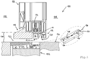
- FIG. 1 shows an additional lock for a door frame and a door having door assembly, wherein the additional lock is designated by the reference numeral 10. Moreover, in FIG. 1 shown a door assembly, which is designated by the reference numeral 100.
- the door assembly 100 has a door frame 102, of which only a lower portion is shown.
- the door assembly 100 has a door frame 102 pivotally mounted on the door leaf 106, of which also only a lower portion is shown.
- the door leaf 106 serves to separate an inner side 108 (secured side) from an outer side 110 (unsecured side).
- the door leaf 106 has on the underside a drive rod 112 with a locking pin.
- the additional lock 10 is mounted on the underside of the door leaf 106, for example screwed, and cooperates with a locking pin of the drive rod 112.
- the additional lock 10 serves to bridge the folding air 114 between the underside of the door leaf 106 and a lower part of the door frame 102.
- the door panel 106 is a conventional door panel with rollover 116 (door panel has rollover 116).
- the door leaf 106 has a cover strip 118, which is arranged in the region of the folded air 114.
- the additional lock 10 is arranged between the cover strip 118 and rollover 116.
- Panel 118, additional latch 10 and rollover 116 form towards the lower part of the door frame 102 toward a nearly flush surface 120 (deviation ⁇ 2 mm). In the illustrated state, the door leaf 106 is not locked to the door frame 102.
- a floor sill 122 is arranged, which forms a flush surface with a floor 124 adjacent to the floor sill 122.
- a strike plate 126 is integrated, which is also arranged flush with the floor 124.
- the striking plate 126 has two locking openings 128.
- the locking apertures 128 taper toward the center of the striker 126 so that a latch member, such as a pivot latch, can engage the latch apertures 128 at the tapers.
- the strike plate 126 has fastening passages 130, on which the strike plate 126 can be screwed, for example.
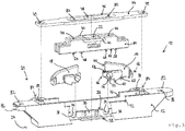
- the additional lock 10 has a housing 12, a displaceable coupling element 14 and two pivot bars 16, 18 (see FIG. 2 and 3 ).
- the coupling element 14 has on a first side 20 of the housing 12 a receptacle 22 which is adapted to receive a locking pin of a drive rod 112 of the door assembly 100.
- the pivot bolt 16, 18 are by displacing the coupling member 14 between a pivoted Position (open position or unlocked position) and a pivoted position (locking position) pivotable.
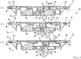
- the pivot bolt 16, 18 is in the pivoted position on a side facing away from the first side 20 side 24 for the purpose of locking out of the housing 12 (see Figure 4c with protruding pivot bolt 16).
- pivot bolt 16, 18 have an identical structure and are provided for reasons of clarity partially only once with reference numerals.
- the coupling element 14 is mounted on a support 26 displaceably in the housing 12, so that the coupling element 14 is translationally displaceable (see FIG. 3 ). For this purpose, sliding portions 28 of the coupling element 14 rest on the support 26.
- the support 26 is designed as a surface of an inner frame 30 of the housing 12 which faces the first side 20 of the housing.
- the pivot bolt 16 serves to lock the door leaf 106 on the door frame 102 (see FIG. 1 ). In this case, the pivot bolt 16 engage in the swung-out state in a locking opening 128 of the strike plate 126.
- There is another pivot bolt 18 is provided which serves to achieve a tilted position of the door leaf 102. For this purpose, the further pivot bolt 18 can also engage in a locking opening 128 of the striking plate 126.
- the coupling element 14 is located in a central position between a first end position and a second end position, the pivot bolt 16, 18 are pivoted (see FIG. 2 . 3 and 4a ). This corresponds to an unlocked position or rotational position in which the door leaf 106 can be pivoted.
- the (first) pivot bolt 16 is pivoted to the pivoted position (see Figure 4c ). This corresponds to a locked position in which the door leaf 106 can not be pivoted.
- the further pivot bolt 18 is in the pivoted position.
- the further pivot bolt 16 is pivoted to the pivoted position (not shown). This corresponds to a tilted position in which the door leaf 106 can be tilted.
- the (first) pivot bolt 16 is in the pivoted position.
- the pivot bolt 16, 18 have pin portions 32, by means of which the pivot bolt 16, 18 are each pivotally mounted in a recess 12 formed on the housing 12 (see FIG. 3 ). As a result, the pivot bolt 16, 18 each pivotable about a pivot axis 36, 38.
- the trough 34 is formed on the inner frame 30.
- the pivot bolt 16, 18 each have a guide portion 40 which cooperates with the displacement of the coupling element 14 in an end position at which the respective pivot bolt 16, 18, with a guide cam 42 of the coupling element 14, that the pivot bolt 16, 18 in the pivoted position is pivoted (see FIG. 3 and 4 with pivoted pivot bolt 16).
- the translational movement of the coupling element 14 is thereby in a Swivel movement of the pivot bolt 16 converted.
- the guide portion 40 is located in the pivoted position of the pivot bolt 16, 18 within a guide slot 44 of the coupling element fourteenth
- the pivoting bars 16, 18 have a nose portion 46 which, when displacing the coupling element 14 from an end position in the direction of the central position of such a pocket 48 of the coupling element 14 (see FIG. 6 ) cooperates, that the pivot bolt 16, 18 is pivoted in the pivoted position.
- the nose portion 46 cooperates with a return portion 50 of the pocket 48 of the coupling element 14. If the coupling element 14 is displaced from an end position in the direction of the central position, the nose portion 46 slides along the return portion 50, so that the pivot bolt 16, 18 is pivoted to the pivoted position (see Fig.2 and 3 ).
- the pivot bars 16, 18 are secured in the pivoted position respectively by contact of the nose portion 46 with an end face 52 of the pocket 48.
- the end face 52 is located at the opposite end of the return portion 50 of the bag 48.
- the pivot bolt 16, 18 in the swung-out position respectively by contact of the guide portion 40 with an end portion 54 of the guide curve 42 secured (see Fig. 4c ).
- the pivot bolt 16, 18 each have a stop surface 56, with which the pivot bolt 16, 18 in the pivoted position with a stop portion 58 of the housing 12 in contact (see 4c ).
- the pivot bolt 16, 18 each have a step 60, with which the pivot bolt 16, 18 in the pivoted position engages behind the abutment portion 58 of the housing 12.
- the pivot bolt 16, 18 have at the nose portion 46 on a leading edge 62, with the pivot bolt 16, 18 in the pivoted position with an adjoining the pocket 48 contact portion 64 in contact (see Figure 3 ).
- the contact portion 64 forms a portion of the sliding portions 28.
- the pivot bars 16, 18 have an enlarged end portion 66 which is adapted to engage behind a locking opening 128 of the striking plate 126 (see Figure 3 ).
- the pivot bolt 16, 18 a reinforced latch portion 68, via which the pivot bolt 16, 18 can laterally contact the support 26 (inner frame 30) in the housing 12 in contact.
- the coupling element 14 has lateral webs 70, with which the coupling element 14 is guided in formed on the housing 12 recesses 72.
- the recesses 72 are closed at the first side 20 of the housing 12 by a cover 74 (see Fig.2 and 3 ).
- the housing 12 is flush with the first side 20 by means of a cover 74, wherein the cover 74 has a passage 76 for a locking pin.
- the passage 76 has an elongate cross section.
- an enlarged passage section 78 is centrally formed, through which a locking pin can be performed through the passage 76.
- the passage 76 may be formed such that the locking pin, the adjoining the enlarged passage section 78 sections 80th engages behind. Performing the locking pin would thus be possible only in the extended passage section 78.
- the cover 74 also has fastening passages 79 by means of which the cover 74 can be fastened to the housing 12, for example screwed or riveted.
- a strike plate 126 is provided, in which at least one of the pivot bolt 16, 18 engages in the swung-out position (see closing plate Fig. 1 ).
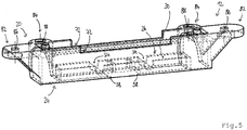
- the housing 12 has attachment tabs 82 and / or lateral attachment tabs 84 with passages 86, 88, with which the additional lock 10 attached to a door assembly 100, in particular can be screwed.
Landscapes
- Engineering & Computer Science (AREA)
- Mechanical Engineering (AREA)
- Structural Engineering (AREA)
- Hinges (AREA)
Priority Applications (3)
| Application Number | Priority Date | Filing Date | Title |
|---|---|---|---|
| PL17161280T PL3375962T3 (pl) | 2017-03-16 | 2017-03-16 | Dodatkowa blokada do zespołu drzwiowego |
| EP17161280.7A EP3375962B1 (fr) | 2017-03-16 | 2017-03-16 | Verrouillage supplémentaire pour un système de porte |
| DE202017105264.8U DE202017105264U1 (de) | 2017-03-16 | 2017-08-31 | Zusatzverriegelung für eine Türanordnung |
Applications Claiming Priority (1)
| Application Number | Priority Date | Filing Date | Title |
|---|---|---|---|
| EP17161280.7A EP3375962B1 (fr) | 2017-03-16 | 2017-03-16 | Verrouillage supplémentaire pour un système de porte |
Publications (2)
| Publication Number | Publication Date |
|---|---|
| EP3375962A1 true EP3375962A1 (fr) | 2018-09-19 |
| EP3375962B1 EP3375962B1 (fr) | 2019-02-27 |
Family
ID=58347261
Family Applications (1)
| Application Number | Title | Priority Date | Filing Date |
|---|---|---|---|
| EP17161280.7A Active EP3375962B1 (fr) | 2017-03-16 | 2017-03-16 | Verrouillage supplémentaire pour un système de porte |
Country Status (3)
| Country | Link |
|---|---|
| EP (1) | EP3375962B1 (fr) |
| DE (1) | DE202017105264U1 (fr) |
| PL (1) | PL3375962T3 (fr) |
Families Citing this family (3)
| Publication number | Priority date | Publication date | Assignee | Title |
|---|---|---|---|---|
| DE102017218071A1 (de) * | 2017-10-11 | 2019-04-11 | Aug. Winkhaus Gmbh & Co. Kg | Verschluss für einen Treibstangenbeschlag |
| DE202018003080U1 (de) * | 2018-07-03 | 2018-08-06 | Kfv Karl Fliether Gmbh & Co. Kg | Schloss mit Schwenkriegel |
| EP4265870B1 (fr) * | 2022-04-20 | 2025-05-07 | Locinox | Système de blocage motorisé monté au sol et système de fermeture le comprenant |
Citations (5)
| Publication number | Priority date | Publication date | Assignee | Title |
|---|---|---|---|---|
| GB2340535A (en) * | 1998-08-07 | 2000-02-23 | Trojan Hardware & Designs Ltd | Locking mechanism |
| DE202004001339U1 (de) * | 2004-01-23 | 2004-04-01 | Gretsch-Unitas GmbH Baubeschläge | An einer Stulpschiene befestigbare Verriegelungsvorrichtung |
| EP2458120A2 (fr) * | 2010-11-30 | 2012-05-30 | Aug. Winkhaus GmbH & Co. KG | Fermeture d'espagnolette |
| US20130152647A1 (en) * | 2011-11-29 | 2013-06-20 | Assa Abloy Australia Pty Limited | Lock |
| EP2957702A1 (fr) | 2014-06-17 | 2015-12-23 | Grundmeier KG | Système de seuil de porte pour une porte d'entrée, porte de magasin ou similaire |
-
2017
- 2017-03-16 EP EP17161280.7A patent/EP3375962B1/fr active Active
- 2017-03-16 PL PL17161280T patent/PL3375962T3/pl unknown
- 2017-08-31 DE DE202017105264.8U patent/DE202017105264U1/de active Active
Patent Citations (5)
| Publication number | Priority date | Publication date | Assignee | Title |
|---|---|---|---|---|
| GB2340535A (en) * | 1998-08-07 | 2000-02-23 | Trojan Hardware & Designs Ltd | Locking mechanism |
| DE202004001339U1 (de) * | 2004-01-23 | 2004-04-01 | Gretsch-Unitas GmbH Baubeschläge | An einer Stulpschiene befestigbare Verriegelungsvorrichtung |
| EP2458120A2 (fr) * | 2010-11-30 | 2012-05-30 | Aug. Winkhaus GmbH & Co. KG | Fermeture d'espagnolette |
| US20130152647A1 (en) * | 2011-11-29 | 2013-06-20 | Assa Abloy Australia Pty Limited | Lock |
| EP2957702A1 (fr) | 2014-06-17 | 2015-12-23 | Grundmeier KG | Système de seuil de porte pour une porte d'entrée, porte de magasin ou similaire |
Also Published As
| Publication number | Publication date |
|---|---|
| EP3375962B1 (fr) | 2019-02-27 |
| DE202017105264U1 (de) | 2017-09-18 |
| PL3375962T3 (pl) | 2019-08-30 |
Similar Documents
| Publication | Publication Date | Title |
|---|---|---|
| DE102021129920B3 (de) | Türband und Tür | |
| DE102017129427B3 (de) | Scharnierverschluss | |
| WO2020007830A1 (fr) | Ensemble de ferrures pré-assemblé et dispositif de ferrure pour une fenêtre ou une porte | |
| EP3102759B1 (fr) | Ferrure d'un battant de fenêtres ou de portes, au moins relevable et coulissant | |
| EP3798390B2 (fr) | Installation de pliage | |
| DE202022100517U1 (de) | Profilanordnung eines Fensters oder einer Tür mit einem Flügelprofil, insbesondere einem Schiebeflügelprofil | |
| EP3375962B1 (fr) | Verrouillage supplémentaire pour un système de porte | |
| EP1312743A2 (fr) | Dispositif de blocage pour un vantail coulissant et levant; ferrure du type crémone avec un tel dispositif; porte ou fenêtre coulissante et levante avec un tel dispositif | |
| DE8913826U1 (de) | Verriegelungsvorrichtung für ein Fenster, eine Tür o.dgl. | |
| DE102021115490B4 (de) | Feststellvorrichtung für beidseitig angeschlagene Tür | |
| EP4146888B1 (fr) | Ensemble charnière à actionnement commun | |
| DE19501509C1 (de) | Beschlag für Fenster, Türen, Klappen oder sonstige Verschlußöffnungen | |
| EP1759081B1 (fr) | Dispositif orientable | |
| EP0500125B1 (fr) | Dispositif de blocage pour fenêtres ou portes | |
| DE102020112148B3 (de) | Scharnierverschluss | |
| EP1425489B1 (fr) | Ferrure oscillobattante | |
| EP1818489A1 (fr) | Fenêtre ou porte de sécurité inhibant l'effraction | |
| EP0429981B1 (fr) | Ferrure arrangée en feuillure pour portes ou fenêtres oscillo-battantes, en particulier avec encadrement en bois | |
| EP3444417B1 (fr) | Système de stockage pour ouvertures de bâtiment | |
| DE19609846A1 (de) | Gleitblech und elektrischer Türöffner mit einem solchen Gleitblech | |
| EP0625235A1 (fr) | Porte de securite et dispositif de securite pour le montage dans une porte | |
| EP1498563A1 (fr) | Dispositif pour creer une fente d'aeration | |
| DE102017202727B4 (de) | Verdeckt angeordneter Beschlag für Fenster, Türen oder dergleichen | |
| EP1715125A2 (fr) | Ferrures pour fenêtre oscillobattante avec une position pour créer une fente de ventilation | |
| DE102024114865A1 (de) | Verriegelungsbeschlag und Tür- oder Fensteranordnung |
Legal Events
| Date | Code | Title | Description |
|---|---|---|---|
| PUAI | Public reference made under article 153(3) epc to a published international application that has entered the european phase |
Free format text: ORIGINAL CODE: 0009012 |
|
| STAA | Information on the status of an ep patent application or granted ep patent |
Free format text: STATUS: REQUEST FOR EXAMINATION WAS MADE |
|
| 17P | Request for examination filed |
Effective date: 20171121 |
|
| AK | Designated contracting states |
Kind code of ref document: A1 Designated state(s): AL AT BE BG CH CY CZ DE DK EE ES FI FR GB GR HR HU IE IS IT LI LT LU LV MC MK MT NL NO PL PT RO RS SE SI SK SM TR |
|
| AX | Request for extension of the european patent |
Extension state: BA ME |
|
| GRAP | Despatch of communication of intention to grant a patent |
Free format text: ORIGINAL CODE: EPIDOSNIGR1 |
|
| STAA | Information on the status of an ep patent application or granted ep patent |
Free format text: STATUS: GRANT OF PATENT IS INTENDED |
|
| RIC1 | Information provided on ipc code assigned before grant |
Ipc: E05C 9/18 20060101AFI20181003BHEP Ipc: E05B 63/12 20060101ALI20181003BHEP Ipc: E05B 9/02 20060101ALN20181003BHEP |
|
| INTG | Intention to grant announced |
Effective date: 20181025 |
|
| GRAS | Grant fee paid |
Free format text: ORIGINAL CODE: EPIDOSNIGR3 |
|
| GRAA | (expected) grant |
Free format text: ORIGINAL CODE: 0009210 |
|
| STAA | Information on the status of an ep patent application or granted ep patent |
Free format text: STATUS: THE PATENT HAS BEEN GRANTED |
|
| AK | Designated contracting states |
Kind code of ref document: B1 Designated state(s): AL AT BE BG CH CY CZ DE DK EE ES FI FR GB GR HR HU IE IS IT LI LT LU LV MC MK MT NL NO PL PT RO RS SE SI SK SM TR |
|
| REG | Reference to a national code |
Ref country code: GB Ref legal event code: FG4D Free format text: NOT ENGLISH |
|
| REG | Reference to a national code |
Ref country code: CH Ref legal event code: EP |
|
| REG | Reference to a national code |
Ref country code: DE Ref legal event code: R096 Ref document number: 502017000804 Country of ref document: DE |
|
| REG | Reference to a national code |
Ref country code: CH Ref legal event code: NV Representative=s name: DREISS PATENTANWAELTE PARTG MBB, DE Ref country code: AT Ref legal event code: REF Ref document number: 1101577 Country of ref document: AT Kind code of ref document: T Effective date: 20190315 |
|
| REG | Reference to a national code |
Ref country code: IE Ref legal event code: FG4D Free format text: LANGUAGE OF EP DOCUMENT: GERMAN |
|
| REG | Reference to a national code |
Ref country code: NL Ref legal event code: FP |
|
| REG | Reference to a national code |
Ref country code: LT Ref legal event code: MG4D |
|
| PG25 | Lapsed in a contracting state [announced via postgrant information from national office to epo] |
Ref country code: PT Free format text: LAPSE BECAUSE OF FAILURE TO SUBMIT A TRANSLATION OF THE DESCRIPTION OR TO PAY THE FEE WITHIN THE PRESCRIBED TIME-LIMIT Effective date: 20190627 Ref country code: SE Free format text: LAPSE BECAUSE OF FAILURE TO SUBMIT A TRANSLATION OF THE DESCRIPTION OR TO PAY THE FEE WITHIN THE PRESCRIBED TIME-LIMIT Effective date: 20190227 Ref country code: LT Free format text: LAPSE BECAUSE OF FAILURE TO SUBMIT A TRANSLATION OF THE DESCRIPTION OR TO PAY THE FEE WITHIN THE PRESCRIBED TIME-LIMIT Effective date: 20190227 Ref country code: FI Free format text: LAPSE BECAUSE OF FAILURE TO SUBMIT A TRANSLATION OF THE DESCRIPTION OR TO PAY THE FEE WITHIN THE PRESCRIBED TIME-LIMIT Effective date: 20190227 Ref country code: NO Free format text: LAPSE BECAUSE OF FAILURE TO SUBMIT A TRANSLATION OF THE DESCRIPTION OR TO PAY THE FEE WITHIN THE PRESCRIBED TIME-LIMIT Effective date: 20190527 |
|
| PG25 | Lapsed in a contracting state [announced via postgrant information from national office to epo] |
Ref country code: IS Free format text: LAPSE BECAUSE OF FAILURE TO SUBMIT A TRANSLATION OF THE DESCRIPTION OR TO PAY THE FEE WITHIN THE PRESCRIBED TIME-LIMIT Effective date: 20190627 Ref country code: BG Free format text: LAPSE BECAUSE OF FAILURE TO SUBMIT A TRANSLATION OF THE DESCRIPTION OR TO PAY THE FEE WITHIN THE PRESCRIBED TIME-LIMIT Effective date: 20190527 Ref country code: RS Free format text: LAPSE BECAUSE OF FAILURE TO SUBMIT A TRANSLATION OF THE DESCRIPTION OR TO PAY THE FEE WITHIN THE PRESCRIBED TIME-LIMIT Effective date: 20190227 Ref country code: LV Free format text: LAPSE BECAUSE OF FAILURE TO SUBMIT A TRANSLATION OF THE DESCRIPTION OR TO PAY THE FEE WITHIN THE PRESCRIBED TIME-LIMIT Effective date: 20190227 Ref country code: HR Free format text: LAPSE BECAUSE OF FAILURE TO SUBMIT A TRANSLATION OF THE DESCRIPTION OR TO PAY THE FEE WITHIN THE PRESCRIBED TIME-LIMIT Effective date: 20190227 Ref country code: GR Free format text: LAPSE BECAUSE OF FAILURE TO SUBMIT A TRANSLATION OF THE DESCRIPTION OR TO PAY THE FEE WITHIN THE PRESCRIBED TIME-LIMIT Effective date: 20190528 |
|
| PG25 | Lapsed in a contracting state [announced via postgrant information from national office to epo] |
Ref country code: RO Free format text: LAPSE BECAUSE OF FAILURE TO SUBMIT A TRANSLATION OF THE DESCRIPTION OR TO PAY THE FEE WITHIN THE PRESCRIBED TIME-LIMIT Effective date: 20190227 Ref country code: AL Free format text: LAPSE BECAUSE OF FAILURE TO SUBMIT A TRANSLATION OF THE DESCRIPTION OR TO PAY THE FEE WITHIN THE PRESCRIBED TIME-LIMIT Effective date: 20190227 Ref country code: SK Free format text: LAPSE BECAUSE OF FAILURE TO SUBMIT A TRANSLATION OF THE DESCRIPTION OR TO PAY THE FEE WITHIN THE PRESCRIBED TIME-LIMIT Effective date: 20190227 Ref country code: DK Free format text: LAPSE BECAUSE OF FAILURE TO SUBMIT A TRANSLATION OF THE DESCRIPTION OR TO PAY THE FEE WITHIN THE PRESCRIBED TIME-LIMIT Effective date: 20190227 Ref country code: EE Free format text: LAPSE BECAUSE OF FAILURE TO SUBMIT A TRANSLATION OF THE DESCRIPTION OR TO PAY THE FEE WITHIN THE PRESCRIBED TIME-LIMIT Effective date: 20190227 Ref country code: ES Free format text: LAPSE BECAUSE OF FAILURE TO SUBMIT A TRANSLATION OF THE DESCRIPTION OR TO PAY THE FEE WITHIN THE PRESCRIBED TIME-LIMIT Effective date: 20190227 Ref country code: CZ Free format text: LAPSE BECAUSE OF FAILURE TO SUBMIT A TRANSLATION OF THE DESCRIPTION OR TO PAY THE FEE WITHIN THE PRESCRIBED TIME-LIMIT Effective date: 20190227 |
|
| REG | Reference to a national code |
Ref country code: DE Ref legal event code: R097 Ref document number: 502017000804 Country of ref document: DE |
|
| PG25 | Lapsed in a contracting state [announced via postgrant information from national office to epo] |
Ref country code: SM Free format text: LAPSE BECAUSE OF FAILURE TO SUBMIT A TRANSLATION OF THE DESCRIPTION OR TO PAY THE FEE WITHIN THE PRESCRIBED TIME-LIMIT Effective date: 20190227 Ref country code: LU Free format text: LAPSE BECAUSE OF NON-PAYMENT OF DUE FEES Effective date: 20190316 |
|
| PG25 | Lapsed in a contracting state [announced via postgrant information from national office to epo] |
Ref country code: MC Free format text: LAPSE BECAUSE OF FAILURE TO SUBMIT A TRANSLATION OF THE DESCRIPTION OR TO PAY THE FEE WITHIN THE PRESCRIBED TIME-LIMIT Effective date: 20190227 |
|
| PLBE | No opposition filed within time limit |
Free format text: ORIGINAL CODE: 0009261 |
|
| STAA | Information on the status of an ep patent application or granted ep patent |
Free format text: STATUS: NO OPPOSITION FILED WITHIN TIME LIMIT |
|
| PG25 | Lapsed in a contracting state [announced via postgrant information from national office to epo] |
Ref country code: IE Free format text: LAPSE BECAUSE OF NON-PAYMENT OF DUE FEES Effective date: 20190316 |
|
| 26N | No opposition filed |
Effective date: 20191128 |
|
| PG25 | Lapsed in a contracting state [announced via postgrant information from national office to epo] |
Ref country code: TR Free format text: LAPSE BECAUSE OF FAILURE TO SUBMIT A TRANSLATION OF THE DESCRIPTION OR TO PAY THE FEE WITHIN THE PRESCRIBED TIME-LIMIT Effective date: 20190227 |
|
| REG | Reference to a national code |
Ref country code: DE Ref legal event code: R082 Ref document number: 502017000804 Country of ref document: DE |
|
| PG25 | Lapsed in a contracting state [announced via postgrant information from national office to epo] |
Ref country code: MT Free format text: LAPSE BECAUSE OF FAILURE TO SUBMIT A TRANSLATION OF THE DESCRIPTION OR TO PAY THE FEE WITHIN THE PRESCRIBED TIME-LIMIT Effective date: 20190227 |
|
| PG25 | Lapsed in a contracting state [announced via postgrant information from national office to epo] |
Ref country code: CY Free format text: LAPSE BECAUSE OF FAILURE TO SUBMIT A TRANSLATION OF THE DESCRIPTION OR TO PAY THE FEE WITHIN THE PRESCRIBED TIME-LIMIT Effective date: 20190227 |
|
| PG25 | Lapsed in a contracting state [announced via postgrant information from national office to epo] |
Ref country code: HU Free format text: LAPSE BECAUSE OF FAILURE TO SUBMIT A TRANSLATION OF THE DESCRIPTION OR TO PAY THE FEE WITHIN THE PRESCRIBED TIME-LIMIT; INVALID AB INITIO Effective date: 20170316 |
|
| PG25 | Lapsed in a contracting state [announced via postgrant information from national office to epo] |
Ref country code: SI Free format text: LAPSE BECAUSE OF FAILURE TO SUBMIT A TRANSLATION OF THE DESCRIPTION OR TO PAY THE FEE WITHIN THE PRESCRIBED TIME-LIMIT Effective date: 20190227 |
|
| GBPC | Gb: european patent ceased through non-payment of renewal fee |
Effective date: 20210316 |
|
| PG25 | Lapsed in a contracting state [announced via postgrant information from national office to epo] |
Ref country code: GB Free format text: LAPSE BECAUSE OF NON-PAYMENT OF DUE FEES Effective date: 20210316 |
|
| PG25 | Lapsed in a contracting state [announced via postgrant information from national office to epo] |
Ref country code: MK Free format text: LAPSE BECAUSE OF FAILURE TO SUBMIT A TRANSLATION OF THE DESCRIPTION OR TO PAY THE FEE WITHIN THE PRESCRIBED TIME-LIMIT Effective date: 20190227 |
|
| P01 | Opt-out of the competence of the unified patent court (upc) registered |
Effective date: 20230509 |
|
| PGFP | Annual fee paid to national office [announced via postgrant information from national office to epo] |
Ref country code: CH Payment date: 20250401 Year of fee payment: 9 |
|
| REG | Reference to a national code |
Ref country code: CH Ref legal event code: U11 Free format text: ST27 STATUS EVENT CODE: U-0-0-U10-U11 (AS PROVIDED BY THE NATIONAL OFFICE) Effective date: 20260401 |
|
| PGFP | Annual fee paid to national office [announced via postgrant information from national office to epo] |
Ref country code: DE Payment date: 20260319 Year of fee payment: 10 |
|
| PGFP | Annual fee paid to national office [announced via postgrant information from national office to epo] |
Ref country code: AT Payment date: 20260320 Year of fee payment: 10 |
|
| PGFP | Annual fee paid to national office [announced via postgrant information from national office to epo] |
Ref country code: BE Payment date: 20260319 Year of fee payment: 10 Ref country code: IT Payment date: 20260324 Year of fee payment: 10 |
|
| PGFP | Annual fee paid to national office [announced via postgrant information from national office to epo] |
Ref country code: NL Payment date: 20260319 Year of fee payment: 10 |
|
| PGFP | Annual fee paid to national office [announced via postgrant information from national office to epo] |
Ref country code: FR Payment date: 20260320 Year of fee payment: 10 |
|
| PGFP | Annual fee paid to national office [announced via postgrant information from national office to epo] |
Ref country code: PL Payment date: 20260302 Year of fee payment: 10 |