EP3375974A1 - Ensemble joint d'étanchéité arrière de liaison extensible - Google Patents
Ensemble joint d'étanchéité arrière de liaison extensible Download PDFInfo
- Publication number
- EP3375974A1 EP3375974A1 EP18170068.3A EP18170068A EP3375974A1 EP 3375974 A1 EP3375974 A1 EP 3375974A1 EP 18170068 A EP18170068 A EP 18170068A EP 3375974 A1 EP3375974 A1 EP 3375974A1
- Authority
- EP
- European Patent Office
- Prior art keywords
- protrusions
- tubular member
- outer surfaces
- adjacent inner
- metallic annular
- Prior art date
- Legal status (The legal status is an assumption and is not a legal conclusion. Google has not performed a legal analysis and makes no representation as to the accuracy of the status listed.)
- Granted
Links
Images

Classifications
-
- E—FIXED CONSTRUCTIONS
- E21—EARTH OR ROCK DRILLING; MINING
- E21B—EARTH OR ROCK DRILLING; OBTAINING OIL, GAS, WATER, SOLUBLE OR MELTABLE MATERIALS OR A SLURRY OF MINERALS FROM WELLS
- E21B33/00—Sealing or packing boreholes or wells
- E21B33/10—Sealing or packing boreholes or wells in the borehole
- E21B33/12—Packers; Plugs
- E21B33/128—Packers; Plugs with a member expanded radially by axial pressure
-
- E—FIXED CONSTRUCTIONS
- E21—EARTH OR ROCK DRILLING; MINING
- E21B—EARTH OR ROCK DRILLING; OBTAINING OIL, GAS, WATER, SOLUBLE OR MELTABLE MATERIALS OR A SLURRY OF MINERALS FROM WELLS
- E21B43/00—Methods or apparatus for obtaining oil, gas, water, soluble or meltable materials or a slurry of minerals from wells
- E21B43/02—Subsoil filtering
- E21B43/10—Setting of casings, screens, liners or the like in wells
- E21B43/103—Setting of casings, screens, liners or the like in wells of expandable casings, screens, liners, or the like
-
- E—FIXED CONSTRUCTIONS
- E21—EARTH OR ROCK DRILLING; MINING
- E21B—EARTH OR ROCK DRILLING; OBTAINING OIL, GAS, WATER, SOLUBLE OR MELTABLE MATERIALS OR A SLURRY OF MINERALS FROM WELLS
- E21B33/00—Sealing or packing boreholes or wells
- E21B33/10—Sealing or packing boreholes or wells in the borehole
- E21B33/12—Packers; Plugs
- E21B33/127—Packers; Plugs with inflatable sleeve
-
- E—FIXED CONSTRUCTIONS
- E21—EARTH OR ROCK DRILLING; MINING
- E21B—EARTH OR ROCK DRILLING; OBTAINING OIL, GAS, WATER, SOLUBLE OR MELTABLE MATERIALS OR A SLURRY OF MINERALS FROM WELLS
- E21B43/00—Methods or apparatus for obtaining oil, gas, water, soluble or meltable materials or a slurry of minerals from wells
- E21B43/02—Subsoil filtering
- E21B43/10—Setting of casings, screens, liners or the like in wells
- E21B43/103—Setting of casings, screens, liners or the like in wells of expandable casings, screens, liners, or the like
- E21B43/108—Expandable screens or perforated liners
Definitions
- the present invention relates to equipment and methods used in subterranean wells and, more particularly, to an expandable tie back seal.
- Wellbores are typically formed by drilling and thereafter lining a borehole with steel pipe called casing.
- the casing provides support to the wellbore and facilitates the isolation of certain areas of the wellbore adjacent hydrocarbon bearing formations.
- the casing typically extends down the wellbore from the surface of the well and the annular area between the outside of the casing and the borehole in the earth is filled with cement to permanently set the casing in the wellbore.
- wells are completed with the remote perforating of liner to provide a fluid path for hydrocarbons to enter the wellbore where they flow into a screened portion of another smaller tubular or production tubing.
- the wellbore around the tubing is isolated with packers to close the annular area and urge the hydrocarbons into the production tubing.
- the last string of liner extending into the wellbore is itself pre-slotted or perforated to receive and carry hydrocarbons upwards in the wellbore.
- production tubing is usually connected to the top of the liner to serve as a conduit to the surface of the well. In this manner, the liner is "tied back" to the surface of the well.
- the production tubing is inserted in the top of a liner in a sealing relationship, usually accomplished by the use of a polished bore receptacle in the liner top.
- a polished bore receptacle has a smooth cylindrical inner bore designed to receive and seal a tubular having a seal assembly on its lower end.
- the polished bore receptacle and seal assembly combination allows the production tubing to be "stung" into the liner in a sealing relationship and be selectively removed there from.
- the term "polished bore receptacle” refers to a device used to locate and seal a first tubular in a second tubular.
- Well-known technology permits wellbore tubular members to be expanded in situ.
- the technology permits the physical attachment of a smaller tubular to a larger tubular by increasing the outer diameter of a smaller tubular with radial force from within.
- the expansion can be accomplished by a mandrel or a cone-shaped member urged through the tubular to be expanded or by an expander tool run in on a tubular string.
- an expander tool see: U.S. Patent No. 7,779,910, issued August 24, 2010 to Watson , entitled “Expansion Cone For Expandable Liner Hanger", which is incorporated herein by reference for all purposes.
- the term "expander tool” is used herein to refer to any member that used to expand a tubular, such as the roller expander tool, a cone member, hydraulic pressure or any other type of expansion member used in the oil and gas industry.
- Tie back seals typically incorporate elastomers at the seal interface.
- Caustic fluids, high temperatures and high pressures encountered downhole often precipitate degradation of elastomeric seals.
- Degraded seals can develop leaks that can be costly to an operation whether left in place or replaced. When left in place, the quality of a production stream can suffer. When replaced, the cost of equipment and labor as well as costs of lost production, during replacement down-time, will accumulate. Accordingly, there is a need in the art for a highly durable tie back seal without elastomers that provides a reliable seal.
- Embodiments of the present invention generally relate to methods and apparatus for completing a well.
- the invention relates to a system of completing a wellbore through the expansion of tubular.
- embodiments of the present invention relate to a tie back seal system, wherein the first tubular contains a polished bore receptacle configured to seal with the second tubular, thereby providing a sealed connection therebetween.
- the system includes tubular members receptive for forming a tie back seal assembly therein.
- the tie back seal assembly includes two telescoping tubular with the overlapping slip fit portions, at least one which is made from plastically deformable metallic material.
- the interior tubular having radially extending annular protrusions thereon, which when the tubular are plastically deformed to form a tie back seal, the protrusions engage the interior of the outer tubular to improve the sealing and durability of the seal system.
- the method includes: positioning a metal deformable tubular member of the tie back within an outer tubular member; expanding the deformable tubular in a radial direction to contact the outer tubular.
- the expanding step causing the protrusions to engage the outer tubular creating annular contact areas comprising plastic deformation of the interior wall of outer tubular member.
- tie back system and method wherein the axially spaced protrusions on the outer surface of interior tubular member that have a generally triangular-shaped cross section.
- Embodiments of the present invention generally relate to methods and apparatus for completing a well.
- the invention relates to a system of completing a wellbore through the expansion of one or more tubular members. More particularly, embodiments of the present invention relate to the concurrent expansion of a first and second tubular, wherein the first tubular contains a polished bore receptacle for forming a tie back seal, configured to sealingly receive a portion of the second tubular, thereby providing a sealable connection therebetween.
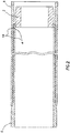
- FIGS 1 and 1A one embodiment of the metal to metal tie back seal configuration used to form a seal between well tubing 5 and well tubing 6.
- the well tubing 6 has been run (installed) into a cased portion of the wellbore (not shown) and hung mounted in the wellbore.
- the mounting is not shown but methods of hanging the tubing 6 in the wellbore are well known in the industry.
- the tubing 5 has been lowered into the wellbore and the lower end inserted in a downhole direction DH into the upper end of the tubing 6.
- the telescoped or overlapping portion of well tubing 5 comprises a tie back seal mandrel 2.
- the telescoped or overlapping portion of well tubing 6 comprises a tie back seal receptacle 1.
- the receptacle can be in the form or a polished bore receptacle.
- the cone 3 of an expander tool is illustrated in Figure 1 in position to be moved through the tie back seal assembly to deform the seal mandrel 2 into sealing engagement with the tie back receptacle 1.
- Tie back seal mandrel 2 comprises a tubular member made from deformable metallic material.
- Mandrel 2 has an outer diameter and wall thickness which when compared to the well tubing 5 is smaller and thinner, respectively.
- the wall thickness of the tic back receptacle 1 is thinner than the wall thickness of the well tubing 6.
- the present invention uses a plurality of radially extending metallic protrusions or ridges 4 which are preferably integrally formed on the reduced diameter outer surface of the seal mandrel 2.
- These protrusions can be integrally formed on the tubular members, for example, by casting and/or machining.
- Ridges 4 are axially spaced apart a distance D.
- Ridges 4 are annular shaped in that they extend continuously around the circumference of the seal mandrel 2 outer surface.
- each protrusion is endless or ring shaped as contrasted with the spiral pattern with ends that is present in a threaded connection.
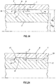
- these protrusions 4 have a tapered cross section which in this embodiment is generally triangular cross-section shaped with the opposed sidewalls 7 inclined toward each other at an angle A in the range of about 30° to about 60°.
- the outer apexes of each of the ridges 4 are flattened to form annular outer walls 8.
- walls 8 have a cylindrical shape to form a cylindrical contact area.
- the wails 8 could have a surface that appears concave or convex when viewed in a cross section, such as Figure 1A .
- Figures 2 and 2A graphically illustrate the metal to metal tie back seal configuration after it has been made up by the cone of expander tool 3.
- the cone 3 of the expander tool can elastically contact the tie back receptacle 1 or deform the tie back mandrel 2 and tie back receptacle 1 in the area of contact.
- the protrusions 4 can deform and/or be embedded in the inner wall of the tie back receptacle 1 to form an annular contact area which acts as a metallic annular seal.
- protrusions 4 can cause plastic deformations 12 to occur in the inner wall 14 of the tie back receptacle 1 as the expansion process is performed.
- the deformations 12 penetrate a distance "P" into the internal surface 14.
- the protrusions 4 can likewise be plastically deformed during the expansion process.
- a plurality of circumferentially extending annular metal to metal contact areas are created, forming a plurality annular seals spaced along the length of the seal assembly.
- a gap "G" may be formed at the interface between the internal surface 14 of the tie back receptacle 1 and the external surface 15 of the seal mandrel 2.
- the gap “G” may be present along all or portions of the interface where the protrusions are not present.
- the interaction between the protrusions 4 and interior wall surface of the tie back receptacle 14 can be altered by the selection of materials for the tubing sections. By forming the receptacle from relatively hard material and the mandrel with a lesser hardness, more deformation of the protrusions would be expected. The dimensions of the sections and cone can be selected to vary the expansion process and amount of deformation in the scaling area.
- the protrusions illustrated in Figure 1A are formed on the interior wall of the tie back receptacle, instead of or in addition to the protrusions on the tie back receptacle.
- compositions and methods are described in terms of “comprising,” “containing,” or “including” various components or steps, the compositions and methods also can “consist essentially of” or “consist of” the various components and steps.
- the words “comprise,” “have,” “include,” and all grammatical variations thereof are each intended to have an open, non-limiting meaning that does not exclude additional elements or steps.
Landscapes
- Geology (AREA)
- Life Sciences & Earth Sciences (AREA)
- Engineering & Computer Science (AREA)
- Mining & Mineral Resources (AREA)
- Geochemistry & Mineralogy (AREA)
- Fluid Mechanics (AREA)
- Environmental & Geological Engineering (AREA)
- General Life Sciences & Earth Sciences (AREA)
- Physics & Mathematics (AREA)
- Earth Drilling (AREA)
- Gasket Seals (AREA)
- Joints With Sleeves (AREA)
- Joints Allowing Movement (AREA)
- Non-Disconnectible Joints And Screw-Threaded Joints (AREA)
- Branch Pipes, Bends, And The Like (AREA)
- Rigid Pipes And Flexible Pipes (AREA)
Priority Applications (1)
| Application Number | Priority Date | Filing Date | Title |
|---|---|---|---|
| EP18170068.3A EP3375974B1 (fr) | 2012-08-28 | 2012-08-28 | Ensemble joint d'étanchéité arrière de liaison extensible |
Applications Claiming Priority (3)
| Application Number | Priority Date | Filing Date | Title |
|---|---|---|---|
| EP18170068.3A EP3375974B1 (fr) | 2012-08-28 | 2012-08-28 | Ensemble joint d'étanchéité arrière de liaison extensible |
| EP12883822.4A EP2890860B1 (fr) | 2012-08-28 | 2012-08-28 | Ensemble d'étanchéité expansible de raccordement pour tubage |
| PCT/US2012/052721 WO2014035380A1 (fr) | 2012-08-28 | 2012-08-28 | Ensemble d'étanchéité expansible de raccordement pour tubage |
Related Parent Applications (1)
| Application Number | Title | Priority Date | Filing Date |
|---|---|---|---|
| EP12883822.4A Division EP2890860B1 (fr) | 2012-08-28 | 2012-08-28 | Ensemble d'étanchéité expansible de raccordement pour tubage |
Publications (2)
| Publication Number | Publication Date |
|---|---|
| EP3375974A1 true EP3375974A1 (fr) | 2018-09-19 |
| EP3375974B1 EP3375974B1 (fr) | 2020-02-26 |
Family
ID=50184019
Family Applications (2)
| Application Number | Title | Priority Date | Filing Date |
|---|---|---|---|
| EP12883822.4A Active EP2890860B1 (fr) | 2012-08-28 | 2012-08-28 | Ensemble d'étanchéité expansible de raccordement pour tubage |
| EP18170068.3A Active EP3375974B1 (fr) | 2012-08-28 | 2012-08-28 | Ensemble joint d'étanchéité arrière de liaison extensible |
Family Applications Before (1)
| Application Number | Title | Priority Date | Filing Date |
|---|---|---|---|
| EP12883822.4A Active EP2890860B1 (fr) | 2012-08-28 | 2012-08-28 | Ensemble d'étanchéité expansible de raccordement pour tubage |
Country Status (9)
| Country | Link |
|---|---|
| US (1) | US9976395B2 (fr) |
| EP (2) | EP2890860B1 (fr) |
| CN (1) | CN104781501B (fr) |
| BR (2) | BR122020007412B1 (fr) |
| CA (1) | CA2883687C (fr) |
| IN (1) | IN2015DN01741A (fr) |
| MX (1) | MX361415B (fr) |
| SG (1) | SG11201501512WA (fr) |
| WO (1) | WO2014035380A1 (fr) |
Families Citing this family (3)
| Publication number | Priority date | Publication date | Assignee | Title |
|---|---|---|---|---|
| AU2017439376B2 (en) * | 2017-11-13 | 2023-06-01 | Halliburton Energy Services, Inc. | Swellable metal for non-elastomeric O-rings, seal stacks, and gaskets |
| US11572749B2 (en) * | 2020-12-16 | 2023-02-07 | Halliburton Energy Services, Inc. | Non-expanding liner hanger |
| CN115538963B (zh) * | 2021-06-30 | 2026-04-17 | 中石化石油工程技术服务有限公司 | 一种悬挂器压裂回接工具 |
Citations (5)
| Publication number | Priority date | Publication date | Assignee | Title |
|---|---|---|---|---|
| US3425719A (en) * | 1967-04-24 | 1969-02-04 | Parker Hannifin Corp | Tube coupling |
| US20040069498A1 (en) * | 2002-10-10 | 2004-04-15 | Simpson Neil A. A. | Method of jointing and running expandable tubulars |
| EP2175101A2 (fr) * | 2008-10-13 | 2010-04-14 | Weatherford Lamb, Inc. | Matrice d'expansion adaptable |
| US7779910B2 (en) | 2008-02-07 | 2010-08-24 | Halliburton Energy Services, Inc. | Expansion cone for expandable liner hanger |
| GB2487669A (en) * | 2011-01-31 | 2012-08-01 | Scott A Benzie | Expanding tubular with grooves and protrusions |
Family Cites Families (25)
| Publication number | Priority date | Publication date | Assignee | Title |
|---|---|---|---|---|
| US4298221A (en) | 1977-01-26 | 1981-11-03 | Hunting Oilfield Services (U.K.) Limited | Pipe connectors |
| SE503459C2 (sv) | 1994-03-15 | 1996-06-17 | Atlas Copco Rocktech Ab | Anordning för permanent hopskarvning av rör |
| US7603758B2 (en) * | 1998-12-07 | 2009-10-20 | Shell Oil Company | Method of coupling a tubular member |
| WO2000037766A2 (fr) * | 1998-12-22 | 2000-06-29 | Weatherford/Lamb, Inc. | Procedes et materiel de façonnage et d'assemblage de tuyaux |
| RU2305169C2 (ru) * | 2001-05-24 | 2007-08-27 | Шелл Интернэшнл Рисерч Маатсхаппий Б.В. | Способ радиального растяжения соединителя для труб |
| US6691789B2 (en) * | 2001-09-10 | 2004-02-17 | Weatherford/Lamb, Inc. | Expandable hanger and packer |
| US6814143B2 (en) | 2001-11-30 | 2004-11-09 | Tiw Corporation | Downhole tubular patch, tubular expander and method |
| US6691686B2 (en) | 2001-12-28 | 2004-02-17 | Visteon Global Technologies, Inc. | Intake manifold with improved exhaust gas recirculation |
| GB0221220D0 (en) | 2002-09-13 | 2002-10-23 | Weatherford Lamb | Expanding coupling |
| US6854522B2 (en) * | 2002-09-23 | 2005-02-15 | Halliburton Energy Services, Inc. | Annular isolators for expandable tubulars in wellbores |
| US6840325B2 (en) | 2002-09-26 | 2005-01-11 | Weatherford/Lamb, Inc. | Expandable connection for use with a swelling elastomer |
| GB2429482B (en) | 2003-02-18 | 2007-09-26 | Enventure Global Technology | Protective compression and tension sleeves for threaded connections for radially expandable tubular members |
| US7441606B2 (en) * | 2003-05-01 | 2008-10-28 | Weatherford/Lamb, Inc. | Expandable fluted liner hanger and packer system |
| US7195073B2 (en) * | 2003-05-01 | 2007-03-27 | Baker Hughes Incorporated | Expandable tieback |
| GB0311721D0 (en) | 2003-05-22 | 2003-06-25 | Weatherford Lamb | Tubing connector |
| WO2005113190A1 (fr) | 2004-04-21 | 2005-12-01 | Grant Prideco, L.P. | Procede et appareil de scellement de joints a dilatation radiale |
| US7380840B2 (en) | 2004-10-26 | 2008-06-03 | Hydril Company | Expandable threaded connection |
| NO324087B1 (no) * | 2005-05-02 | 2007-08-13 | Easy Well Solutions As | Anordning ved ringromspakning |
| US7422068B2 (en) | 2005-05-12 | 2008-09-09 | Baker Hughes Incorporated | Casing patch overshot |
| US7735567B2 (en) * | 2006-04-13 | 2010-06-15 | Baker Hughes Incorporated | Packer sealing element with shape memory material and associated method |
| US7854266B2 (en) * | 2008-09-26 | 2010-12-21 | Halliburton Energy Services, Inc. | Smooth bore latch for tie back receptacle extension |
| ES2464457T3 (es) | 2009-01-12 | 2014-06-02 | Welltec A/S | Barrera anular y sistema de barrera anular |
| US20110308793A1 (en) | 2010-06-17 | 2011-12-22 | Vetco Gray Inc. | High integrity hanger and seal for casing |
| US9057260B2 (en) * | 2011-06-29 | 2015-06-16 | Baker Hughes Incorporated | Through tubing expandable frac sleeve with removable barrier |
| US20130248209A1 (en) * | 2011-07-21 | 2013-09-26 | Halliburton Energy Services, Inc. | High pressure tie back receptacle and seal assembly |
-
2012
- 2012-08-28 CA CA2883687A patent/CA2883687C/fr active Active
- 2012-08-28 CN CN201280075560.2A patent/CN104781501B/zh active Active
- 2012-08-28 EP EP12883822.4A patent/EP2890860B1/fr active Active
- 2012-08-28 MX MX2015002464A patent/MX361415B/es active IP Right Grant
- 2012-08-28 BR BR122020007412-4A patent/BR122020007412B1/pt active IP Right Grant
- 2012-08-28 WO PCT/US2012/052721 patent/WO2014035380A1/fr not_active Ceased
- 2012-08-28 US US14/424,610 patent/US9976395B2/en active Active
- 2012-08-28 SG SG11201501512WA patent/SG11201501512WA/en unknown
- 2012-08-28 EP EP18170068.3A patent/EP3375974B1/fr active Active
- 2012-08-28 BR BR112015004319-4A patent/BR112015004319B1/pt active IP Right Grant
-
2015
- 2015-03-03 IN IN1741DEN2015 patent/IN2015DN01741A/en unknown
Patent Citations (5)
| Publication number | Priority date | Publication date | Assignee | Title |
|---|---|---|---|---|
| US3425719A (en) * | 1967-04-24 | 1969-02-04 | Parker Hannifin Corp | Tube coupling |
| US20040069498A1 (en) * | 2002-10-10 | 2004-04-15 | Simpson Neil A. A. | Method of jointing and running expandable tubulars |
| US7779910B2 (en) | 2008-02-07 | 2010-08-24 | Halliburton Energy Services, Inc. | Expansion cone for expandable liner hanger |
| EP2175101A2 (fr) * | 2008-10-13 | 2010-04-14 | Weatherford Lamb, Inc. | Matrice d'expansion adaptable |
| GB2487669A (en) * | 2011-01-31 | 2012-08-01 | Scott A Benzie | Expanding tubular with grooves and protrusions |
Also Published As
| Publication number | Publication date |
|---|---|
| US9976395B2 (en) | 2018-05-22 |
| MX361415B (es) | 2018-11-30 |
| BR112015004319A2 (pt) | 2017-07-04 |
| US20150198006A1 (en) | 2015-07-16 |
| MX2015002464A (es) | 2015-11-16 |
| BR112015004319B1 (pt) | 2021-03-09 |
| CN104781501B (zh) | 2017-07-28 |
| EP2890860A4 (fr) | 2016-04-27 |
| WO2014035380A1 (fr) | 2014-03-06 |
| CA2883687C (fr) | 2017-03-07 |
| EP2890860B1 (fr) | 2018-05-30 |
| SG11201501512WA (en) | 2015-03-30 |
| EP3375974B1 (fr) | 2020-02-26 |
| CN104781501A (zh) | 2015-07-15 |
| EP2890860A1 (fr) | 2015-07-08 |
| IN2015DN01741A (fr) | 2015-05-29 |
| AU2012388782B2 (en) | 2016-10-06 |
| CA2883687A1 (fr) | 2014-03-06 |
| BR122020007412B1 (pt) | 2021-05-04 |
| AU2012388782A1 (en) | 2015-04-02 |
Similar Documents
| Publication | Publication Date | Title |
|---|---|---|
| US9347298B2 (en) | High pressure tie back receptacle and seal assembly | |
| US7165622B2 (en) | Packer with metal sealing element | |
| EP2675991B1 (fr) | Joints résistants à l'extrusion pour ensemble tubulaire extensible | |
| CA2981934C (fr) | Systeme de blocage d'element de garniture d'etancheite incorporant un mecanisme a iris | |
| EP3535477B1 (fr) | Procédé et système d'étanchéification de cavités dans ou adjacentes à une gaine de ciment durci entourant un tubage de puits | |
| US10100598B2 (en) | Downhole expandable metal tubular | |
| CA2710329A1 (fr) | Fixation de bouchon provisoire composite | |
| US9976395B2 (en) | Expandable tie back seal assembly | |
| AU2016424204B2 (en) | High expansion metal back-up ring for packers and bridge plugs | |
| AU2012388782B9 (en) | Expandable tie back seal assembly | |
| US20070034386A1 (en) | Expandable well barrier | |
| WO2024130016A1 (fr) | Ensemble anneau de secours pour applications de packer |
Legal Events
| Date | Code | Title | Description |
|---|---|---|---|
| PUAI | Public reference made under article 153(3) epc to a published international application that has entered the european phase |
Free format text: ORIGINAL CODE: 0009012 |
|
| STAA | Information on the status of an ep patent application or granted ep patent |
Free format text: STATUS: REQUEST FOR EXAMINATION WAS MADE |
|
| 17P | Request for examination filed |
Effective date: 20180430 |
|
| AC | Divisional application: reference to earlier application |
Ref document number: 2890860 Country of ref document: EP Kind code of ref document: P |
|
| AK | Designated contracting states |
Kind code of ref document: A1 Designated state(s): AL AT BE BG CH CY CZ DE DK EE ES FI FR GB GR HR HU IE IS IT LI LT LU LV MC MK MT NL NO PL PT RO RS SE SI SK SM TR |
|
| GRAP | Despatch of communication of intention to grant a patent |
Free format text: ORIGINAL CODE: EPIDOSNIGR1 |
|
| STAA | Information on the status of an ep patent application or granted ep patent |
Free format text: STATUS: GRANT OF PATENT IS INTENDED |
|
| INTG | Intention to grant announced |
Effective date: 20191015 |
|
| GRAS | Grant fee paid |
Free format text: ORIGINAL CODE: EPIDOSNIGR3 |
|
| GRAA | (expected) grant |
Free format text: ORIGINAL CODE: 0009210 |
|
| STAA | Information on the status of an ep patent application or granted ep patent |
Free format text: STATUS: THE PATENT HAS BEEN GRANTED |
|
| AC | Divisional application: reference to earlier application |
Ref document number: 2890860 Country of ref document: EP Kind code of ref document: P |
|
| AK | Designated contracting states |
Kind code of ref document: B1 Designated state(s): AL AT BE BG CH CY CZ DE DK EE ES FI FR GB GR HR HU IE IS IT LI LT LU LV MC MK MT NL NO PL PT RO RS SE SI SK SM TR |
|
| REG | Reference to a national code |
Ref country code: GB Ref legal event code: FG4D |
|
| REG | Reference to a national code |
Ref country code: CH Ref legal event code: EP |
|
| REG | Reference to a national code |
Ref country code: AT Ref legal event code: REF Ref document number: 1237844 Country of ref document: AT Kind code of ref document: T Effective date: 20200315 |
|
| REG | Reference to a national code |
Ref country code: IE Ref legal event code: FG4D |
|
| REG | Reference to a national code |
Ref country code: DE Ref legal event code: R096 Ref document number: 602012068175 Country of ref document: DE |
|
| REG | Reference to a national code |
Ref country code: NO Ref legal event code: T2 Effective date: 20200226 |
|
| REG | Reference to a national code |
Ref country code: NL Ref legal event code: FP |
|
| PG25 | Lapsed in a contracting state [announced via postgrant information from national office to epo] |
Ref country code: RS Free format text: LAPSE BECAUSE OF FAILURE TO SUBMIT A TRANSLATION OF THE DESCRIPTION OR TO PAY THE FEE WITHIN THE PRESCRIBED TIME-LIMIT Effective date: 20200226 Ref country code: FI Free format text: LAPSE BECAUSE OF FAILURE TO SUBMIT A TRANSLATION OF THE DESCRIPTION OR TO PAY THE FEE WITHIN THE PRESCRIBED TIME-LIMIT Effective date: 20200226 |
|
| REG | Reference to a national code |
Ref country code: LT Ref legal event code: MG4D |
|
| PG25 | Lapsed in a contracting state [announced via postgrant information from national office to epo] |
Ref country code: SE Free format text: LAPSE BECAUSE OF FAILURE TO SUBMIT A TRANSLATION OF THE DESCRIPTION OR TO PAY THE FEE WITHIN THE PRESCRIBED TIME-LIMIT Effective date: 20200226 Ref country code: LV Free format text: LAPSE BECAUSE OF FAILURE TO SUBMIT A TRANSLATION OF THE DESCRIPTION OR TO PAY THE FEE WITHIN THE PRESCRIBED TIME-LIMIT Effective date: 20200226 Ref country code: HR Free format text: LAPSE BECAUSE OF FAILURE TO SUBMIT A TRANSLATION OF THE DESCRIPTION OR TO PAY THE FEE WITHIN THE PRESCRIBED TIME-LIMIT Effective date: 20200226 Ref country code: GR Free format text: LAPSE BECAUSE OF FAILURE TO SUBMIT A TRANSLATION OF THE DESCRIPTION OR TO PAY THE FEE WITHIN THE PRESCRIBED TIME-LIMIT Effective date: 20200527 Ref country code: IS Free format text: LAPSE BECAUSE OF FAILURE TO SUBMIT A TRANSLATION OF THE DESCRIPTION OR TO PAY THE FEE WITHIN THE PRESCRIBED TIME-LIMIT Effective date: 20200626 Ref country code: BG Free format text: LAPSE BECAUSE OF FAILURE TO SUBMIT A TRANSLATION OF THE DESCRIPTION OR TO PAY THE FEE WITHIN THE PRESCRIBED TIME-LIMIT Effective date: 20200526 |
|
| PG25 | Lapsed in a contracting state [announced via postgrant information from national office to epo] |
Ref country code: CZ Free format text: LAPSE BECAUSE OF FAILURE TO SUBMIT A TRANSLATION OF THE DESCRIPTION OR TO PAY THE FEE WITHIN THE PRESCRIBED TIME-LIMIT Effective date: 20200226 Ref country code: SK Free format text: LAPSE BECAUSE OF FAILURE TO SUBMIT A TRANSLATION OF THE DESCRIPTION OR TO PAY THE FEE WITHIN THE PRESCRIBED TIME-LIMIT Effective date: 20200226 Ref country code: RO Free format text: LAPSE BECAUSE OF FAILURE TO SUBMIT A TRANSLATION OF THE DESCRIPTION OR TO PAY THE FEE WITHIN THE PRESCRIBED TIME-LIMIT Effective date: 20200226 Ref country code: ES Free format text: LAPSE BECAUSE OF FAILURE TO SUBMIT A TRANSLATION OF THE DESCRIPTION OR TO PAY THE FEE WITHIN THE PRESCRIBED TIME-LIMIT Effective date: 20200226 Ref country code: LT Free format text: LAPSE BECAUSE OF FAILURE TO SUBMIT A TRANSLATION OF THE DESCRIPTION OR TO PAY THE FEE WITHIN THE PRESCRIBED TIME-LIMIT Effective date: 20200226 Ref country code: PT Free format text: LAPSE BECAUSE OF FAILURE TO SUBMIT A TRANSLATION OF THE DESCRIPTION OR TO PAY THE FEE WITHIN THE PRESCRIBED TIME-LIMIT Effective date: 20200719 Ref country code: DK Free format text: LAPSE BECAUSE OF FAILURE TO SUBMIT A TRANSLATION OF THE DESCRIPTION OR TO PAY THE FEE WITHIN THE PRESCRIBED TIME-LIMIT Effective date: 20200226 Ref country code: EE Free format text: LAPSE BECAUSE OF FAILURE TO SUBMIT A TRANSLATION OF THE DESCRIPTION OR TO PAY THE FEE WITHIN THE PRESCRIBED TIME-LIMIT Effective date: 20200226 Ref country code: SM Free format text: LAPSE BECAUSE OF FAILURE TO SUBMIT A TRANSLATION OF THE DESCRIPTION OR TO PAY THE FEE WITHIN THE PRESCRIBED TIME-LIMIT Effective date: 20200226 |
|
| REG | Reference to a national code |
Ref country code: AT Ref legal event code: MK05 Ref document number: 1237844 Country of ref document: AT Kind code of ref document: T Effective date: 20200226 |
|
| REG | Reference to a national code |
Ref country code: DE Ref legal event code: R097 Ref document number: 602012068175 Country of ref document: DE |
|
| PLBE | No opposition filed within time limit |
Free format text: ORIGINAL CODE: 0009261 |
|
| STAA | Information on the status of an ep patent application or granted ep patent |
Free format text: STATUS: NO OPPOSITION FILED WITHIN TIME LIMIT |
|
| PG25 | Lapsed in a contracting state [announced via postgrant information from national office to epo] |
Ref country code: AT Free format text: LAPSE BECAUSE OF FAILURE TO SUBMIT A TRANSLATION OF THE DESCRIPTION OR TO PAY THE FEE WITHIN THE PRESCRIBED TIME-LIMIT Effective date: 20200226 Ref country code: IT Free format text: LAPSE BECAUSE OF FAILURE TO SUBMIT A TRANSLATION OF THE DESCRIPTION OR TO PAY THE FEE WITHIN THE PRESCRIBED TIME-LIMIT Effective date: 20200226 |
|
| 26N | No opposition filed |
Effective date: 20201127 |
|
| PG25 | Lapsed in a contracting state [announced via postgrant information from national office to epo] |
Ref country code: PL Free format text: LAPSE BECAUSE OF FAILURE TO SUBMIT A TRANSLATION OF THE DESCRIPTION OR TO PAY THE FEE WITHIN THE PRESCRIBED TIME-LIMIT Effective date: 20200226 Ref country code: SI Free format text: LAPSE BECAUSE OF FAILURE TO SUBMIT A TRANSLATION OF THE DESCRIPTION OR TO PAY THE FEE WITHIN THE PRESCRIBED TIME-LIMIT Effective date: 20200226 |
|
| PG25 | Lapsed in a contracting state [announced via postgrant information from national office to epo] |
Ref country code: MC Free format text: LAPSE BECAUSE OF FAILURE TO SUBMIT A TRANSLATION OF THE DESCRIPTION OR TO PAY THE FEE WITHIN THE PRESCRIBED TIME-LIMIT Effective date: 20200226 |
|
| REG | Reference to a national code |
Ref country code: CH Ref legal event code: PL |
|
| PG25 | Lapsed in a contracting state [announced via postgrant information from national office to epo] |
Ref country code: LU Free format text: LAPSE BECAUSE OF NON-PAYMENT OF DUE FEES Effective date: 20200828 Ref country code: LI Free format text: LAPSE BECAUSE OF NON-PAYMENT OF DUE FEES Effective date: 20200831 Ref country code: CH Free format text: LAPSE BECAUSE OF NON-PAYMENT OF DUE FEES Effective date: 20200831 |
|
| REG | Reference to a national code |
Ref country code: BE Ref legal event code: MM Effective date: 20200831 |
|
| PG25 | Lapsed in a contracting state [announced via postgrant information from national office to epo] |
Ref country code: FR Free format text: LAPSE BECAUSE OF NON-PAYMENT OF DUE FEES Effective date: 20200831 |
|
| PG25 | Lapsed in a contracting state [announced via postgrant information from national office to epo] |
Ref country code: BE Free format text: LAPSE BECAUSE OF NON-PAYMENT OF DUE FEES Effective date: 20200831 Ref country code: IE Free format text: LAPSE BECAUSE OF NON-PAYMENT OF DUE FEES Effective date: 20200828 |
|
| PG25 | Lapsed in a contracting state [announced via postgrant information from national office to epo] |
Ref country code: TR Free format text: LAPSE BECAUSE OF FAILURE TO SUBMIT A TRANSLATION OF THE DESCRIPTION OR TO PAY THE FEE WITHIN THE PRESCRIBED TIME-LIMIT Effective date: 20200226 Ref country code: MT Free format text: LAPSE BECAUSE OF FAILURE TO SUBMIT A TRANSLATION OF THE DESCRIPTION OR TO PAY THE FEE WITHIN THE PRESCRIBED TIME-LIMIT Effective date: 20200226 Ref country code: CY Free format text: LAPSE BECAUSE OF FAILURE TO SUBMIT A TRANSLATION OF THE DESCRIPTION OR TO PAY THE FEE WITHIN THE PRESCRIBED TIME-LIMIT Effective date: 20200226 |
|
| PG25 | Lapsed in a contracting state [announced via postgrant information from national office to epo] |
Ref country code: MK Free format text: LAPSE BECAUSE OF FAILURE TO SUBMIT A TRANSLATION OF THE DESCRIPTION OR TO PAY THE FEE WITHIN THE PRESCRIBED TIME-LIMIT Effective date: 20200226 Ref country code: AL Free format text: LAPSE BECAUSE OF FAILURE TO SUBMIT A TRANSLATION OF THE DESCRIPTION OR TO PAY THE FEE WITHIN THE PRESCRIBED TIME-LIMIT Effective date: 20200226 |
|
| PGFP | Annual fee paid to national office [announced via postgrant information from national office to epo] |
Ref country code: GB Payment date: 20250602 Year of fee payment: 14 |
|
| PGFP | Annual fee paid to national office [announced via postgrant information from national office to epo] |
Ref country code: NL Payment date: 20250723 Year of fee payment: 14 |
|
| PGFP | Annual fee paid to national office [announced via postgrant information from national office to epo] |
Ref country code: DE Payment date: 20250724 Year of fee payment: 14 |
|
| PGFP | Annual fee paid to national office [announced via postgrant information from national office to epo] |
Ref country code: NO Payment date: 20250725 Year of fee payment: 14 |