EP3375978B1 - Filmgekühlte turbinenschaufel - Google Patents
Filmgekühlte turbinenschaufel Download PDFInfo
- Publication number
- EP3375978B1 EP3375978B1 EP18154029.5A EP18154029A EP3375978B1 EP 3375978 B1 EP3375978 B1 EP 3375978B1 EP 18154029 A EP18154029 A EP 18154029A EP 3375978 B1 EP3375978 B1 EP 3375978B1
- Authority
- EP
- European Patent Office
- Prior art keywords
- cooling
- section
- blade
- turbine
- passage
- Prior art date
- Legal status (The legal status is an assumption and is not a legal conclusion. Google has not performed a legal analysis and makes no representation as to the accuracy of the status listed.)
- Active
Links
Images



Classifications
-
- F—MECHANICAL ENGINEERING; LIGHTING; HEATING; WEAPONS; BLASTING
- F01—MACHINES OR ENGINES IN GENERAL; ENGINE PLANTS IN GENERAL; STEAM ENGINES
- F01D—NON-POSITIVE DISPLACEMENT MACHINES OR ENGINES, e.g. STEAM TURBINES
- F01D5/00—Blades; Blade-carrying members; Heating, heat-insulating, cooling or antivibration means on the blades or the members
- F01D5/12—Blades
- F01D5/14—Form or construction
- F01D5/18—Hollow blades, i.e. blades with cooling or heating channels or cavities; Heating, heat-insulating or cooling means on blades
- F01D5/187—Convection cooling
-
- F—MECHANICAL ENGINEERING; LIGHTING; HEATING; WEAPONS; BLASTING
- F01—MACHINES OR ENGINES IN GENERAL; ENGINE PLANTS IN GENERAL; STEAM ENGINES
- F01D—NON-POSITIVE DISPLACEMENT MACHINES OR ENGINES, e.g. STEAM TURBINES
- F01D5/00—Blades; Blade-carrying members; Heating, heat-insulating, cooling or antivibration means on the blades or the members
- F01D5/12—Blades
- F01D5/14—Form or construction
- F01D5/18—Hollow blades, i.e. blades with cooling or heating channels or cavities; Heating, heat-insulating or cooling means on blades
- F01D5/187—Convection cooling
- F01D5/188—Convection cooling with an insert in the blade cavity to guide the cooling fluid, e.g. forming a separation wall
-
- F—MECHANICAL ENGINEERING; LIGHTING; HEATING; WEAPONS; BLASTING
- F01—MACHINES OR ENGINES IN GENERAL; ENGINE PLANTS IN GENERAL; STEAM ENGINES
- F01D—NON-POSITIVE DISPLACEMENT MACHINES OR ENGINES, e.g. STEAM TURBINES
- F01D25/00—Component parts, details, or accessories, not provided for in, or of interest apart from, other groups
- F01D25/08—Cooling; Heating; Heat-insulation
- F01D25/12—Cooling
-
- F—MECHANICAL ENGINEERING; LIGHTING; HEATING; WEAPONS; BLASTING
- F01—MACHINES OR ENGINES IN GENERAL; ENGINE PLANTS IN GENERAL; STEAM ENGINES
- F01D—NON-POSITIVE DISPLACEMENT MACHINES OR ENGINES, e.g. STEAM TURBINES
- F01D5/00—Blades; Blade-carrying members; Heating, heat-insulating, cooling or antivibration means on the blades or the members
- F01D5/12—Blades
- F01D5/14—Form or construction
- F01D5/141—Shape, i.e. outer, aerodynamic form
- F01D5/145—Means for influencing boundary layers or secondary circulations
-
- F—MECHANICAL ENGINEERING; LIGHTING; HEATING; WEAPONS; BLASTING
- F01—MACHINES OR ENGINES IN GENERAL; ENGINE PLANTS IN GENERAL; STEAM ENGINES
- F01D—NON-POSITIVE DISPLACEMENT MACHINES OR ENGINES, e.g. STEAM TURBINES
- F01D5/00—Blades; Blade-carrying members; Heating, heat-insulating, cooling or antivibration means on the blades or the members
- F01D5/12—Blades
- F01D5/14—Form or construction
- F01D5/18—Hollow blades, i.e. blades with cooling or heating channels or cavities; Heating, heat-insulating or cooling means on blades
-
- F—MECHANICAL ENGINEERING; LIGHTING; HEATING; WEAPONS; BLASTING
- F01—MACHINES OR ENGINES IN GENERAL; ENGINE PLANTS IN GENERAL; STEAM ENGINES
- F01D—NON-POSITIVE DISPLACEMENT MACHINES OR ENGINES, e.g. STEAM TURBINES
- F01D5/00—Blades; Blade-carrying members; Heating, heat-insulating, cooling or antivibration means on the blades or the members
- F01D5/12—Blades
- F01D5/14—Form or construction
- F01D5/18—Hollow blades, i.e. blades with cooling or heating channels or cavities; Heating, heat-insulating or cooling means on blades
- F01D5/186—Film cooling
-
- F—MECHANICAL ENGINEERING; LIGHTING; HEATING; WEAPONS; BLASTING
- F05—INDEXING SCHEMES RELATING TO ENGINES OR PUMPS IN VARIOUS SUBCLASSES OF CLASSES F01-F04
- F05D—INDEXING SCHEME FOR ASPECTS RELATING TO NON-POSITIVE-DISPLACEMENT MACHINES OR ENGINES, GAS-TURBINES OR JET-PROPULSION PLANTS
- F05D2220/00—Application
- F05D2220/30—Application in turbines
- F05D2220/32—Application in turbines in gas turbines
-
- F—MECHANICAL ENGINEERING; LIGHTING; HEATING; WEAPONS; BLASTING
- F05—INDEXING SCHEMES RELATING TO ENGINES OR PUMPS IN VARIOUS SUBCLASSES OF CLASSES F01-F04
- F05D—INDEXING SCHEME FOR ASPECTS RELATING TO NON-POSITIVE-DISPLACEMENT MACHINES OR ENGINES, GAS-TURBINES OR JET-PROPULSION PLANTS
- F05D2260/00—Function
- F05D2260/20—Heat transfer, e.g. cooling
-
- F—MECHANICAL ENGINEERING; LIGHTING; HEATING; WEAPONS; BLASTING
- F05—INDEXING SCHEMES RELATING TO ENGINES OR PUMPS IN VARIOUS SUBCLASSES OF CLASSES F01-F04
- F05D—INDEXING SCHEME FOR ASPECTS RELATING TO NON-POSITIVE-DISPLACEMENT MACHINES OR ENGINES, GAS-TURBINES OR JET-PROPULSION PLANTS
- F05D2260/00—Function
- F05D2260/20—Heat transfer, e.g. cooling
- F05D2260/202—Heat transfer, e.g. cooling by film cooling
-
- F—MECHANICAL ENGINEERING; LIGHTING; HEATING; WEAPONS; BLASTING
- F05—INDEXING SCHEMES RELATING TO ENGINES OR PUMPS IN VARIOUS SUBCLASSES OF CLASSES F01-F04
- F05D—INDEXING SCHEME FOR ASPECTS RELATING TO NON-POSITIVE-DISPLACEMENT MACHINES OR ENGINES, GAS-TURBINES OR JET-PROPULSION PLANTS
- F05D2260/00—Function
- F05D2260/20—Heat transfer, e.g. cooling
- F05D2260/221—Improvement of heat transfer
- F05D2260/2212—Improvement of heat transfer by creating turbulence
-
- F—MECHANICAL ENGINEERING; LIGHTING; HEATING; WEAPONS; BLASTING
- F05—INDEXING SCHEMES RELATING TO ENGINES OR PUMPS IN VARIOUS SUBCLASSES OF CLASSES F01-F04
- F05D—INDEXING SCHEME FOR ASPECTS RELATING TO NON-POSITIVE-DISPLACEMENT MACHINES OR ENGINES, GAS-TURBINES OR JET-PROPULSION PLANTS
- F05D2270/00—Control
- F05D2270/01—Purpose of the control system
- F05D2270/17—Purpose of the control system to control boundary layer
Definitions
- the present invention relates to turbine blades and a gas turbine having the same.
- the turbine blades of a gas turbine are exposed to high-temperature combustion gas. For this reason, the turbine blades need to be cooled to prevent the high-temperature oxidation of or thinning-induced damage to the turbine blades due to the high-temperature combustion gas.
- One method of cooling a turbine blade is to form film cooling holes on the surface of the blade through which the cooling air flowing in the internal cooling passage of the blade flows out. After flowing out from the film cooling holes, the cooling air flows along the blade surface and forms a cooling film, thereby preventing the entry of the heat of high-temperature combustion gas into the turbine blade.
- the cooling air flowing out of the film cooling holes is mixed with combustion gas, which typically involves mixing loss. This in turn results in reduced heat efficiency of the turbine. For this reason, attempts have been made to improve the outlet-side airfoil at which the pressures of the film cooling holes are low, for the purposes of improving cooling efficiency and reducing the flow rate of the cooling air. By improving cooling efficiency, the amount of cooling air required for cooling the turbine blade can be reduced, which in turn improves the heat efficiency of the turbine.
- EP 2 584 148 A1 describes a turbine blade which has an outer wall having an inner cavity filled with cooling fluid used for film cooling of the turbine blade.
- the trailing edge of the cooling film is inclined such that distribution of velocity of the cooling fluid flow is formed asymmetrically over the cross-section of the passage way.
- US 2016/0061451 A1 describes a combustor for a turbine engine with a first liner having a first surface and a second surface.
- a second liner forms a combustion chamber with the second side of the first liner, and the combustion chamber is configured to receive an air fuel mixture for combustion therein.
- the first liner defines a plurality of effusion cooling holes.
- EP 3 205 822 A1 describes a component for a combustion section or a turbine section of a gas turbine engine.
- the component defines a core air flow path and includes a wall.
- the wall has a hot side and an opposite cold side. The hot side is exposed to and defines the core air flow path when the component is installed in the gas turbine engine.
- the wall is manufactured to include surface contouring on the cold side of the wall to structurally accommodate the thermal management feature of the wall.
- EP 2 993 304 A1 describes a gas turbine engine component, including a wall that provides an exterior surface and an interior flow path surface. A film cooling hole that has an inlet is provided on a protrusion arranged on the wall.
- GB 2 262 314 A describes a gas turbine engine aerofoil with a linear cooling air passage interconnecting the hollow air foil interior with its exterior surface.
- EP 3 012 407 A1 describes a wall of a gas turbine engine component with a wall comprising an external surface adjacent to a gas path and an internal surface adjacent to an internal flow oath.
- a film hole has an inlet at the internal surface and an outlet at the external surface.
- a flow accumulator adjacent to the inlet protrudes from the internal surface.
- the present invention has been made in view of the above problems, and an object of the invention is to further improve the cooling efficiency of turbine blades.
- the invention allows for further improvement in the cooling performance of turbine blades.
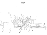
- FIG. 1 illustrates an example of a gas turbine to which are applied turbine blades according to an embodiment of the invention.
- the gas turbine 100 includes a compressor 1, a combustor 2, and a turbine 3.
- the compressor 1 compresses the air 4 drawn in via an intake section (not illustrated) to generate high-pressure compressed air (air used for combustion) 5 and supplies it to the combustor 2.
- the combustor 2 mixes the compressed air 5 supplied from the compressor 1 with the fuel supplied from a fuel supply system (not illustrated) and combusts the mixed gas.
- the resultant combustion gas (working fluid) 6 is supplied to the turbine 3.
- the turbine rotor 8 (described later in detail) of the turbine 3 is rotated by the expansion of the combustion gas 6 supplied from the combustor 2.
- the turbine rotor 8 is connected to the rotor of the compressor 1 (not illustrated), whereby the rotational power obtained in the turbine 3 is used to drive the compressor 1.
- a generator or a load (not illustrated) is also connected to the turbine rotor 8, whereby the power remaining after subtracting the power needed to drive the compressor 1 from the rotational power obtained in the turbine 3 is converted into electric power by the generator.
- the combustion gas 6 that has driven the turbine rotor 8 is eventually discharged into the atmosphere as turbine exhaust.
- the turbine 3 includes a stator 7 and the turbine rotor 8 that rotates relative to the stator 7.
- the stator 7 includes a casing 9 and stator vanes (turbine blades) 10.
- the casing 9 is a cylindrical member forming the outer wall of the turbine 3. Housed within the casing 9 are the stator vanes 10 and the turbine rotor 8.
- the stator vanes 10 are provided on the circumferentially inner wall 9a of the casing 9 along a circumferential direction of the turbine rotor 8.
- the stator vanes 10 each includes a circumferentially outer endwall section (stator vane circumferentially outer endwall section) 11, a blade section (stator vane blade section) 12, and a circumferentially inner endwall section (stator vane circumferentially inner endwall section) 13.
- the circumferentially outer endwall section 11 is a cylindrical member extending in a circumferential direction of the turbine rotor 8 and is supported by the circumferentially inner wall 9a of the casing 9.
- the blade section 12 extends from the circumferentially inner surface of the circumferentially outer endwall section 11 toward the radially inner side of the turbine rotor 8.
- the blade section 12 has an internal cooling passage (not illustrated).
- the circumferentially inner endwall section 13 is also a cylindrical member extending in a circumferential direction of the turbine rotor 8 and is provided on the radially inner side of the circumferentially outer endwall section 11.
- the blade section 12 is connected to the circumferentially outer surface of the circumferentially inner endwall section 13. In other words, the blade section 12 is fixed between the circumferentially outer endwall section 11 and the circumferentially inner endwall section 13.
- the turbine rotor 8 includes a turbine shaft section 14 and rotor blades (turbine blades) 15.
- the turbine shaft section 14 extends along the rotary shaft (central axis) 43 of the turbine 3 and includes a turbine disk 16.
- the turbine disk 16 extends from the circumferentially outer surface of the turbine shaft section 14 toward the radially outer side.
- the turbine disk 16 includes an inner hollow section 22 (described later).
- the rotor blades 15 are provided on the circumferentially outer surface of the turbine disk 16 along a circumferential direction of the turbine rotor 8. Together with the turbine shaft section 14, the rotor blades 15 rotate relative to the rotary shaft 43 by the combustion gas 6 flowing through a combustion gas passage (working fluid passage) 17.
- the stator vanes 10 and the rotor blades 15 are provided alternately in the flowing direction of the combustion gas 6. That is, from the entrance of the combustion gas passage 17 to the downstream side of the flowing direction of the combustion gas 6, a stator vane 10 is first provided, followed by a rotor blade 15, then by another stator vane 10 and another rotor blade 15, and so forth.
- a pair of a stator vane 10 and a rotor blade 15 that are adjacent to each other in the direction from the entrance of the combustion gas passage 17 to the downstream side of the flowing direction of the combustion gas 6 constitutes a blade stage. Note that hereinafter the upstream and downstream sides of the flowing direction of the combustion gas 6 are referred to simply as “the combustion upstream side” and “the combustion downstream side.”
- FIG. 2 is a cross section illustrating the internal structure of a rotor blade according to the present embodiment.
- the rotor blade 15 includes a circumferentially inner endwall section (rotor blade circumferentially inner endwall section) 18 and a blade section (rotor-blade blade section) 19.
- the circumferentially inner endwall section 18 is provided on the turbine disk 16 such that it faces the circumferentially inner wall 9a of the casing 9 with the combustion gas passage 17 placed therebetween.
- the combustion gas passage 17 is the annular space surrounded by the circumferentially outer surface of the circumferentially inner endwall section 13, the circumferentially outer surface 18a of the circumferentially inner endwall section 18, the circumferentially inner wall 9a of the casing 9, and the circumferentially inner surface of the circumferentially outer endwall section 11.
- the circumferentially inner walls of the combustion gas passage 17 are formed by the circumferentially outer surface of the circumferentially inner endwall section 13 and the circumferentially outer surface 18a of the circumferentially inner endwall section 18 while the circumferentially outer walls of the combustion gas passage 17 are formed by the circumferentially inner wall 9a of the casing 9 and the circumferentially inner surface of the circumferentially outer endwall section 11.
- the blade section 19 extends from the circumferentially outer surface 18a of the circumferentially inner endwall section 18 toward the radially outer side.
- a space 20 is formed between the circumferentially outer section (radially outer side end) of the blade section 19 and the circumferentially inner wall 9a of the casing 9.
- the blade section 19 includes an internal cooling passage 23.
- the cooling passage 23 communicates with the inner hollow section 22 of the turbine disk 16 via an opening (cooling air inlet) 21.
- the blade section 19 is cooled from within by the cooling air flowing through the cooling passage 23.
- the cooling passage 23 includes a first cooling passage 23a, a second cooling passage 23b, and a third cooling passage 23c.
- the first cooling passage 23a is the section located on the combustion downstream side of the cooling passage 23 and extends from the opening 21 toward the radially outer side.
- Multiple pin fins 25 are provided in the first cooling passage 23a to disturb the flow of the cooling air flowing through the first cooling passage 23a.
- the second cooling passage 23b is the section located on the combustion upstream side of the first cooling passage 23a in the cooling passage 23.
- the second cooling passage 23b communicates with the other side (radially outer side) end of the first cooling passage 23a and extends therefrom toward the radially inner side.
- the third cooling passage 23c is the section located on the combustion upstream side of the second cooling passage 23b in the cooling passage 23.
- the third cooling passage 23c communicates with the one end (radially inner end) of the second cooling passage 23b and extends therefrom toward the radially outer side.
- Multiple fins 26 are provided in the second cooling passage 23b and the third cooling passage 23c. The fins 26 are used to promote heat exchange between the cooling air flowing through the second and third cooling passages 23b and 23c and the blade section 19.
- the cooling passage 23 includes the first, second, and third cooling passages 23a, 23b, and 23c, and the blade section 19 is cooled by convection cooling.
- FIG. 3 is a cross section taken along arrow III-III of FIG. 2 and viewed from the direction of the arrow.
- the cross section of the blade section 19 illustrated in FIG. 3 is hereinafter referred to also as the blade cross section.
- the blade section 19 includes a positive pressure surface (pressure surface) 27b located on the front side of the blade, a negative pressure surface 27a located across from the positive pressure surface 27b or on the back side of the blade, a blade leading edge 28a, and a blade trailing edge 28b.
- a positive pressure surface 27b located on the front side of the blade
- a negative pressure surface 27a located across from the positive pressure surface 27b or on the back side of the blade
- a blade leading edge 28a located across from the positive pressure surface 27b or on the back side of the blade
- a blade leading edge 28a located across from the positive pressure surface 27b or on the back side of the blade
- a blade leading edge 28a located across from the positive pressure surface 27b or on the back side of the blade
- a blade leading edge 28a located across from the positive pressure surface 27b or on the back side of the blade
- a blade leading edge 28a located across from the positive pressure surface 27b or on the back side of the blade
- a blade leading edge 28a located across from the
- the blade section 19 is formed such that its thickness (the distance between the positive pressure surface 27b and the negative pressure surface 27a in a direction perpendicular to the blade center line 30) becomes gradually large as viewed from the blade leading edge 28a to the middle of the blade section 19 and becomes gradually small as viewed from the middle of the blade section 19 to the blade trailing edge 28b.
- FIG. 4 is an enlarged view of the dotted area A of FIG. 3 .
- the blade section 19 includes film cooling holes (communication holes) 36 and a projection 37.
- the communication holes 36 establish communication between the third cooling passage 23c and the combustion gas passage 17.
- Each of the communication holes 36 includes an opening (first opening) 39 provided on a wall surface (first wall surface) 38 that faces the third cooling passage 23c and constitutes the circumferentially outer surface of the third cooling passage 23c and an opening (second opening) 40 provided on the negative pressure surface (second wall surface) 27a that faces the combustion gas passage 17 of the blade section 19.
- the first opening 39 is the inlet into which the cooling air (rotor blade cooling air) 35 flowing through the third cooling passage 23c flows while the second opening 40 is the outlet from which the cooling air 35 flows out via the communication hole 36.
- the communication holes 36 are provided in a longitudinal direction of the blade section 19 (in a direction perpendicular to the drawing plane of FIG. 4 ).
- Each of the communication holes 36 is formed such that the second opening 40 is displaced relative to the first opening 39 toward the combustion downstream side. If the second opening 40 and the first opening 39 are assumed to coincide with each other in the flowing direction of the combustion gas, connecting the centers of the first and second openings results in the reference central axis X of the communication hole being obtained.
- the actual central axis Y of the communication hole 36 obtained by connecting the centers of the first and second openings is slanted relative to the reference central axis X toward the combustion downstream side.
- the first and second openings 39 and 40 of the communication hole 36 are ellipse-shaped. The tilt angle.
- N of the communication hole 36 (the angle between the reference central axis X and the actual central axis Y) is set such that the cooling air 35 discharged toward the combustion gas passage 17 through the communication hole 36 flows as close to the outer surfaces of the blade section 19 as possible.
- the projection 37 is provided on the downstream side of the flowing direction of the cooling air 35 in the first opening 39 of the communication hole 36 (in FIG. 4 , on the combustion downstream side of the first opening 39 of the communication hole 36).
- the upstream and downstream sides of the flowing direction of the cooling air 35 are referred to also as “the cooling upstream side” and “the cooling downstream side.”
- the projection 37 protrudes from the first wall surface 38 toward the third cooling passage 23c.
- the length L1 from the negative pressure surface 27a of the blade section 19 measured at the farthest position of the projection 37 from the first wall surface 38 (also referred to as "the apex") is larger than the length L between the negative pressure surface 27a of the blade section 19 and the first wall surface 38.
- the passage area of the section of the third cooling passage 23c where the projection 37 is provided is smaller than that of the other section where the projection 37 is not provided.
- the third cooling passage 23c is made narrower where the projection 37 is provided.
- the projection 37 includes a slope section 37A and a curved section 37B.
- the slope section 37A is a slope ascending from the first wall surface 38 in the direction opposite the flowing direction of the cooling air 35 (toward the cooling upstream side); thus, it ascends toward the third cooling passage 23c.
- the length L2 from the negative pressure surface 27a of the blade section 19 to the slope section 37A gets larger as it advances against the flowing direction of the cooling air 35.
- the slope section 37A forms a smooth surface that lies between the curved section 37B and the first wall surface 38.
- the curved section 37B forms a convex-shaped surface protruding toward the third cooling passage 23c; in other words, it forms an arc-shaped surface that lies between the slope section 37A and the first opening 39 of the communication hole 36.
- the curvature of the curved section 37B is determined to achieve such a smooth arc-shaped surface.
- FIG. 5 is an enlarged view of the communication hole 36 as viewed from the third cooling passage 23c.
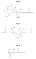
- FIG. 6 is a cross section taken along arrow VI-VI of FIG. 5 and viewed from the direction of the arrow.
- FIG. 7 is a cross section taken along arrow VII-VII of FIG. 5 and viewed from the direction of the arrow.
- FIG. 8 is a cross section taken along arrow VIII-VIII of FIG. 5 and viewed from the direction of the arrow.
- the projection 37 is provided in the area W1 of the area W (described later in detail).
- the area W is formed between the edge of the first opening 39 and the ellipse F' surrounding the first opening 39, and the area W1 is the section of the area W enclosed by the two boundaries B1 and B2.
- a curved section (second curved section) 41 is formed at the edge of the first opening 39 of the communication hole 36.
- the second curved section 41 forms a smooth curved surface from the first wall surface 38 to the first opening 39; in other words, it forms a convex-shaped surface facing the third cooling passage 23c.
- the second curved section 41 is provided adjacent to the projection 37 in a circumferential direction of the first opening 39.
- the second curved section 41 is provided in the areas W2 and W3 that are adjacent to the area W1 of the area W in a circumferential direction of the first opening 39.
- the projection 37 and the second curved section 41 are in contact with the first wall surface 38 on the same plane. If the length of the projection 37 from the first wall surface 38 to the apex of the projection 37 is defined as the height h1 (see FIG. 6 ) and the length of the second curved section 41 from the first wall surface 38 to the edge of the second curved section 41 on the side of the first opening 39 is defined as the height h2 (see FIG. 7 ), the height h1 of the projection 37 is smaller at sections closer to the second curved section 41 while the height h2 of the second curved section 41 is smaller at sections closer to the projection 37 in the circumferential direction of the first opening 39.
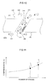
- FIG. 9 is a flowchart illustrating the procedures for forming the projection 37 and the second curved section 41. The procedures for forming the projection 37 and the second curved section 41 are described below with reference to FIGS. 5 and 9 .
- a reference angle M is determined based on the oscillatory width of the cooling air 35 flowing through the communication hole 36.
- the oscillatory width of the cooling air 35 is an index indicating the degrees of deviation of the flowing direction of the cooling air 35 relative to the central axis of the communication hole 36.
- the reference angle M is a circumferential angle relative to the longitudinal axis of the first opening 39 of the communication hole 36 when the communication hole 36 is viewed from the side of the third cooling passage 23c, and as stated above, the reference angle M is determined based on the oscillatory width of the cooling air 35.
- the reference angle M is 45 degrees, for example.
- the longitudinal axis C of the first opening 39 of the communication hole 36 is hereinafter also called the communication hole longitudinal axis.
- the lines (tangents) A1 and A2 are determined.
- the lines A1 and A2 are the lines that are in contact with the edge of the first opening 39 of the communication hole 36 and have the reference angle M determined in Step S1 relative to the communication hole longitudinal axis C.
- the reference point O is determined.
- the reference point O is the intersecting point among the lines A1 and A2 and an extension of the communication hole longitudinal axis C that runs in the direction opposite the flowing direction of the cooling air 35.
- the contact points S and P are determined.
- the contact points S and P are the points at which the lines A1 and A2 are in contact with the edge of the first opening 39 of the communication hole 36.
- the ellipse F' is determined.
- the ellipse F' is inscribed in the lines A1 and A2, and an extension of its longitudinal axis C' passes the reference point O and matches the communication hole longitudinal axis C.
- the contact points R and Q at which the lines A1 and A2 are in contact with the ellipse F' are determined.
- the area W is determined. First, the curve G1 that starts from the contact point Q, passes the contact points P and S clockwise, and ends at the contact point R is obtained. Then, the curve G2 that starts from contact point R, passes along the ellipse F' clockwise, and ends at the contact point Q is obtained.
- the area W is determined by excluding the first opening 39 of the communication hole 36 from the area enclosed by the curves G1 and G2. The area W is not limited to particular sizes as long as it does not interfere with the areas W of the adjacent communication holes 36 arranged in a longitudinal direction of the blade section 19.
- the area W is divided into the first area W1, the second area W2, and the third area W3.
- the first area W1 is larger than the second area W2 and the third area W3, and the second area W2 and the third area W3 are equal in size.
- the projection 37 is formed in the first area W1, and the second curved section 41 is formed in the second and third areas W2 and W3.
- An example of the method of forming the projection 37 and the second curved section 41 is precision casting. By precision casting, the blade section 19 having the projection 37 can be formed.
- part of the compressed air is extracted from an intermediate stage or the outlet of the compressor 1 (see FIG. 1 ) to use it as the cooling air.
- the compressed air extracted from the compressor 1 flows into the turbine shaft section 14 of the turbine rotor 8 as the cooling air via a hole section of the turbine shaft section 14 (not illustrated).
- part of the cooling air flowing through the turbine shaft section 14 flows into the combustion gas passage 17 via the gap 33 formed between the rotor blade 15 and the adjacent stator vane 10 located on the combustion upstream side and via the gap 34 formed between the rotor blade 15 and the adjacent stator vane 10 located on the combustion downstream side and merges with the combustion gas 6.
- Part of the cooling air flowing through the turbine shaft section 14 also flows into the hollow section 22 of the turbine disk 16 as the cooling air 35.
- the cooling air 35 flowing through the hollow section 22 enters the first cooling passage 23a via the opening 21 while cooling the turbine disk 16 from within.
- the cooling air 35 that has entered the first cooling passage 23a flows through it toward the radially outer side (in the upper direction of FIG. 2 ).
- the cooling air 35 flowing through the first cooling passage 23a is directed toward the radially inner side (in the lower direction of FIG. 2 ) at the radially outer end of the first cooling passage 23a and thus flows into the second cooling passage 23b.
- the cooling air 35 that has entered the second cooling passage 23b flows through it toward the radially inner side.
- the cooling air 35 flowing through the second cooling passage 23b is directed toward the radially outer side at the radially inner end of the second cooling passage 23b and thus flows into the third cooling passage 23c.
- the cooling air 35 that has entered the third cooling passage 23c flows through it toward the radially outer side.
- the cooling air 35 flowing through the third cooling passage 23c flows into the combustion gas passage 17 via the opening 42, thus merging with the combustion gas 6.
- the cooling air 35 flowing close to the first wall surface 38 collides with the cooling-upstream-side wall surface at the curved section 37B of the projection 37 and decelerates.
- the cooling air 35 that has decelerated is directed toward the communication hole 36 along the surface of the curved section 37B.
- the cooling air 35 directed into the communication hole 36 flows through it to be discharged into the combustion gas passage 17.
- the cooling air 35 discharged into the combustion gas passage 17 flows along the surface of the blade section 19 to form a cooling film. Meanwhile the cooling air 35 that has flowed close to the first wall surface 38 and has not entered the communication hole 36 flows toward the cooling downstream side along the surface of the curved section 37B.
- the passage area of the section of the third cooling passage 23c where the projection 37 is provided is smaller than that of the other section where the projection 37 is not provided.
- the cooling air 35 flowing toward the cooling downstream side along the surface of the curved section 37B is accelerated and flows along the surface of the slope section 37A.
- the invention is not limited to the embodiment described above but allows various modifications.
- the above embodiment is intended to be illustrative only, and the invention does not necessarily need to have all the components of the embodiment. For example, some components of the embodiment can be removed or replaced.
- the essential object of the invention is to improve the cooling performance of turbine blades, and the invention is not limited to the above structure as long as that essential object can be achieved.
- a communication hole 36 establishes fluid communication between the third cooling passage 23 of the blade section 19 and the combustion gas passage 17.
- the invention is not limited to that structure as long as that essential object can be achieved.
- the' communication hole 36 it is also possible for the' communication hole 36 to establish communication among the first cooling passage 23a and the second cooling passage 23b of the blade section 19 and the combustion gas passage 17. In that case as well, advantageous effects similar to those of the above embodiment can be obtained.
Landscapes
- Engineering & Computer Science (AREA)
- Mechanical Engineering (AREA)
- General Engineering & Computer Science (AREA)
- Physics & Mathematics (AREA)
- Fluid Mechanics (AREA)
- Turbine Rotor Nozzle Sealing (AREA)
Claims (4)
- Turbinenschaufel (15), die Folgendes umfasst:eine erste Wandfläche (38), die einem Kühldurchgang (23) zugewandt ist, durch den Kühlluft (35) strömt;eine zweite Wandfläche (27a), die einem Arbeitsfluiddurchgang (17) zugewandt ist, durch den ein Arbeitsfluid (6) strömt; undeine Kommunikationsloch (36), das eine Kommunikation zwischen dem Kühldurchgang (23) und dem Arbeitsfluiddurchgang (17) schafft; undeinen Vorsprung (37), der auf einer stromabwärts gelegenen Seite der Strömungsrichtung der Kühlluft (35) in einer Öffnung (39) des Kommunikationslochs (36) vorgesehen ist, wobei die Öffnung (39) in der ersten Wandfläche (38) gebildet ist und der Vorsprung (37) von der ersten Wandfläche (38) zum Kühldurchgang (23) vorsteht, dadurch gekennzeichnet, dassein gekrümmter Abschnitt (41) angrenzend an den Vorsprung (37) in einer Umfangsrichtung der Öffnung (39) vorgesehen ist, wobei der gekrümmte Abschnitt (41) nahtlos zwischen der ersten Wandfläche (38) und der Öffnung (39) verbunden ist, wobeider Vorsprung (37) und der gekrümmte Abschnitt (41) auf derselben Ebene in Kontakt mit der ersten Wandfläche (38) sind.
- Turbinenschaufel (15) nach Anspruch 1, wobei der Vorsprung einen geneigten Abschnitt (37A), der an der ersten Wandfläche (38) gebildet ist, umfasst, wobei der geneigte Abschnitt (37A) in einer Richtung, die zu der Strömungsrichtung der Kühlluft (35) entgegengesetzt ist, zum Kühldurchgang (23) ansteigt und ein weiterer gekrümmter Abschnitt (37B) als ein konvexer Abschnitt auf Seiten des Kühldurchgangs (23) gebildet ist, wobei der weitere gekrümmte Abschnitt (37B) mit der Öffnung (39) in Form eines Bogens verbunden ist.
- Turbinenschaufel (15) nach einem der Ansprüche 1 bis 2, wobei die Öffnung (39) ellipsenförmig ist.
- Gasturbine (100), die Schaufelstufen umfasst, die die Turbinenschaufel (15) nach einem der Ansprüche 1 bis 3 umfassen.
Applications Claiming Priority (1)
| Application Number | Priority Date | Filing Date | Title |
|---|---|---|---|
| JP2017049392A JP6767901B2 (ja) | 2017-03-15 | 2017-03-15 | タービン翼及びそれを備えたガスタービン |
Publications (2)
| Publication Number | Publication Date |
|---|---|
| EP3375978A1 EP3375978A1 (de) | 2018-09-19 |
| EP3375978B1 true EP3375978B1 (de) | 2019-09-04 |
Family
ID=61094268
Family Applications (1)
| Application Number | Title | Priority Date | Filing Date |
|---|---|---|---|
| EP18154029.5A Active EP3375978B1 (de) | 2017-03-15 | 2018-01-30 | Filmgekühlte turbinenschaufel |
Country Status (6)
| Country | Link |
|---|---|
| US (1) | US10415398B2 (de) |
| EP (1) | EP3375978B1 (de) |
| JP (1) | JP6767901B2 (de) |
| KR (1) | KR102008606B1 (de) |
| CN (1) | CN108625905B (de) |
| RU (1) | RU2685403C1 (de) |
Family Cites Families (13)
| Publication number | Priority date | Publication date | Assignee | Title |
|---|---|---|---|---|
| US2489683A (en) * | 1943-11-19 | 1949-11-29 | Edward A Stalker | Turbine |
| US5383766A (en) * | 1990-07-09 | 1995-01-24 | United Technologies Corporation | Cooled vane |
| GB2262314A (en) * | 1991-12-10 | 1993-06-16 | Rolls Royce Plc | Air cooled gas turbine engine aerofoil. |
| US5771577A (en) * | 1996-05-17 | 1998-06-30 | General Electric Company | Method for making a fluid cooled article with protective coating |
| US7316539B2 (en) * | 2005-04-07 | 2008-01-08 | Siemens Power Generation, Inc. | Vane assembly with metal trailing edge segment |
| US7887300B2 (en) * | 2007-02-27 | 2011-02-15 | Siemens Energy, Inc. | CMC airfoil with thin trailing edge |
| US8052378B2 (en) | 2009-03-18 | 2011-11-08 | General Electric Company | Film-cooling augmentation device and turbine airfoil incorporating the same |
| US8807943B1 (en) * | 2010-02-15 | 2014-08-19 | Florida Turbine Technologies, Inc. | Turbine blade with trailing edge cooling circuit |
| EP2584148A1 (de) * | 2011-10-21 | 2013-04-24 | Siemens Aktiengesellschaft | Filmgekühlte Turbinenschaufel für eine Strömungsmaschine |
| US10101030B2 (en) * | 2014-09-02 | 2018-10-16 | Honeywell International Inc. | Gas turbine engines with plug resistant effusion cooling holes |
| US10982552B2 (en) | 2014-09-08 | 2021-04-20 | Raytheon Technologies Corporation | Gas turbine engine component with film cooling hole |
| US9957810B2 (en) | 2014-10-20 | 2018-05-01 | United Technologies Corporation | Film hole with protruding flow accumulator |
| US10495309B2 (en) | 2016-02-12 | 2019-12-03 | General Electric Company | Surface contouring of a flowpath wall of a gas turbine engine |
-
2017
- 2017-03-15 JP JP2017049392A patent/JP6767901B2/ja active Active
-
2018
- 2018-01-26 KR KR1020180009803A patent/KR102008606B1/ko active Active
- 2018-01-29 RU RU2018103176A patent/RU2685403C1/ru active
- 2018-01-29 CN CN201810084896.4A patent/CN108625905B/zh active Active
- 2018-01-30 US US15/883,564 patent/US10415398B2/en active Active
- 2018-01-30 EP EP18154029.5A patent/EP3375978B1/de active Active
Non-Patent Citations (1)
| Title |
|---|
| None * |
Also Published As
| Publication number | Publication date |
|---|---|
| US20180266255A1 (en) | 2018-09-20 |
| JP2018150913A (ja) | 2018-09-27 |
| JP6767901B2 (ja) | 2020-10-14 |
| CN108625905B (zh) | 2020-11-20 |
| RU2685403C1 (ru) | 2019-04-18 |
| US10415398B2 (en) | 2019-09-17 |
| KR102008606B1 (ko) | 2019-08-07 |
| CN108625905A (zh) | 2018-10-09 |
| EP3375978A1 (de) | 2018-09-19 |
Similar Documents
| Publication | Publication Date | Title |
|---|---|---|
| EP2412925B1 (de) | Turbinenschaufel und gasturbine | |
| US8668453B2 (en) | Cooling system having reduced mass pin fins for components in a gas turbine engine | |
| EP3708272B1 (de) | Gusskern für eine kühlanordnung eines gasturbinenbauteils | |
| EP1630352B1 (de) | Turbinenbauteil | |
| EP2912274B1 (de) | Kühlanordnung für ein gasturbinenbauteil | |
| EP2235328B1 (de) | Schaufelkühlung | |
| EP1990507A1 (de) | Prallkühlungsstruktur | |
| US9181807B2 (en) | Blade member and rotary machine | |
| CN107448300A (zh) | 用于涡轮发动机的翼型件 | |
| JP2006132536A (ja) | エーロフォイルとこれを含んだタービンブレードおよびガスタービンエンジン | |
| JP2005264934A (ja) | タービンエアフォイルおよび冷却回路の入口の配置方法 | |
| EP3184743B1 (de) | Turbinenschaufel mit hinterkantenkühlkreis | |
| CN110043325B (zh) | 带有成组冷却孔的发动机构件 | |
| US20170002685A1 (en) | Guide vane of a gas turbine engine, in particular of an aircraft engine | |
| JP7778221B2 (ja) | ガスタービンの静翼の冷却方法および冷却構造 | |
| US20050042096A1 (en) | Thermally loaded component | |
| EP3375978B1 (de) | Filmgekühlte turbinenschaufel | |
| JPS59231102A (ja) | ガスタ−ビンの翼 | |
| JP7720988B2 (ja) | ガスタービンの静翼の冷却方法および冷却構造 | |
| CN116753037B (zh) | 一种动叶结构及燃气轮机 | |
| CN110382823B (zh) | 涡轮叶片、涡轮及涡轮叶片的冷却方法 | |
| WO2017082907A1 (en) | Turbine airfoil with a cooled trailing edge | |
| WO2024106091A1 (ja) | ガスタービンの静翼の冷却方法および冷却構造 | |
| KR20240055099A (ko) | 터빈 정익 | |
| CN116085058A (zh) | 用于涡轮发动机的具有冷却通道的部件 |
Legal Events
| Date | Code | Title | Description |
|---|---|---|---|
| PUAI | Public reference made under article 153(3) epc to a published international application that has entered the european phase |
Free format text: ORIGINAL CODE: 0009012 |
|
| STAA | Information on the status of an ep patent application or granted ep patent |
Free format text: STATUS: REQUEST FOR EXAMINATION WAS MADE |
|
| 17P | Request for examination filed |
Effective date: 20180206 |
|
| AK | Designated contracting states |
Kind code of ref document: A1 Designated state(s): AL AT BE BG CH CY CZ DE DK EE ES FI FR GB GR HR HU IE IS IT LI LT LU LV MC MK MT NL NO PL PT RO RS SE SI SK SM TR |
|
| AX | Request for extension of the european patent |
Extension state: BA ME |
|
| RIN1 | Information on inventor provided before grant (corrected) |
Inventor name: MIYOSHI, ICHIRO |
|
| GRAP | Despatch of communication of intention to grant a patent |
Free format text: ORIGINAL CODE: EPIDOSNIGR1 |
|
| STAA | Information on the status of an ep patent application or granted ep patent |
Free format text: STATUS: GRANT OF PATENT IS INTENDED |
|
| INTG | Intention to grant announced |
Effective date: 20190509 |
|
| GRAS | Grant fee paid |
Free format text: ORIGINAL CODE: EPIDOSNIGR3 |
|
| GRAA | (expected) grant |
Free format text: ORIGINAL CODE: 0009210 |
|
| STAA | Information on the status of an ep patent application or granted ep patent |
Free format text: STATUS: THE PATENT HAS BEEN GRANTED |
|
| AK | Designated contracting states |
Kind code of ref document: B1 Designated state(s): AL AT BE BG CH CY CZ DE DK EE ES FI FR GB GR HR HU IE IS IT LI LT LU LV MC MK MT NL NO PL PT RO RS SE SI SK SM TR |
|
| REG | Reference to a national code |
Ref country code: GB Ref legal event code: FG4D |
|
| REG | Reference to a national code |
Ref country code: CH Ref legal event code: EP |
|
| REG | Reference to a national code |
Ref country code: AT Ref legal event code: REF Ref document number: 1175616 Country of ref document: AT Kind code of ref document: T Effective date: 20190915 |
|
| REG | Reference to a national code |
Ref country code: DE Ref legal event code: R096 Ref document number: 602018000533 Country of ref document: DE |
|
| REG | Reference to a national code |
Ref country code: IE Ref legal event code: FG4D |
|
| REG | Reference to a national code |
Ref country code: NL Ref legal event code: MP Effective date: 20190904 |
|
| REG | Reference to a national code |
Ref country code: LT Ref legal event code: MG4D |
|
| PG25 | Lapsed in a contracting state [announced via postgrant information from national office to epo] |
Ref country code: SE Free format text: LAPSE BECAUSE OF FAILURE TO SUBMIT A TRANSLATION OF THE DESCRIPTION OR TO PAY THE FEE WITHIN THE PRESCRIBED TIME-LIMIT Effective date: 20190904 Ref country code: HR Free format text: LAPSE BECAUSE OF FAILURE TO SUBMIT A TRANSLATION OF THE DESCRIPTION OR TO PAY THE FEE WITHIN THE PRESCRIBED TIME-LIMIT Effective date: 20190904 Ref country code: NO Free format text: LAPSE BECAUSE OF FAILURE TO SUBMIT A TRANSLATION OF THE DESCRIPTION OR TO PAY THE FEE WITHIN THE PRESCRIBED TIME-LIMIT Effective date: 20191204 Ref country code: LT Free format text: LAPSE BECAUSE OF FAILURE TO SUBMIT A TRANSLATION OF THE DESCRIPTION OR TO PAY THE FEE WITHIN THE PRESCRIBED TIME-LIMIT Effective date: 20190904 Ref country code: BG Free format text: LAPSE BECAUSE OF FAILURE TO SUBMIT A TRANSLATION OF THE DESCRIPTION OR TO PAY THE FEE WITHIN THE PRESCRIBED TIME-LIMIT Effective date: 20191204 Ref country code: FI Free format text: LAPSE BECAUSE OF FAILURE TO SUBMIT A TRANSLATION OF THE DESCRIPTION OR TO PAY THE FEE WITHIN THE PRESCRIBED TIME-LIMIT Effective date: 20190904 |
|
| PG25 | Lapsed in a contracting state [announced via postgrant information from national office to epo] |
Ref country code: LV Free format text: LAPSE BECAUSE OF FAILURE TO SUBMIT A TRANSLATION OF THE DESCRIPTION OR TO PAY THE FEE WITHIN THE PRESCRIBED TIME-LIMIT Effective date: 20190904 Ref country code: GR Free format text: LAPSE BECAUSE OF FAILURE TO SUBMIT A TRANSLATION OF THE DESCRIPTION OR TO PAY THE FEE WITHIN THE PRESCRIBED TIME-LIMIT Effective date: 20191205 Ref country code: RS Free format text: LAPSE BECAUSE OF FAILURE TO SUBMIT A TRANSLATION OF THE DESCRIPTION OR TO PAY THE FEE WITHIN THE PRESCRIBED TIME-LIMIT Effective date: 20190904 Ref country code: ES Free format text: LAPSE BECAUSE OF FAILURE TO SUBMIT A TRANSLATION OF THE DESCRIPTION OR TO PAY THE FEE WITHIN THE PRESCRIBED TIME-LIMIT Effective date: 20190904 Ref country code: AL Free format text: LAPSE BECAUSE OF FAILURE TO SUBMIT A TRANSLATION OF THE DESCRIPTION OR TO PAY THE FEE WITHIN THE PRESCRIBED TIME-LIMIT Effective date: 20190904 |
|
| REG | Reference to a national code |
Ref country code: AT Ref legal event code: MK05 Ref document number: 1175616 Country of ref document: AT Kind code of ref document: T Effective date: 20190904 |
|
| PG25 | Lapsed in a contracting state [announced via postgrant information from national office to epo] |
Ref country code: AT Free format text: LAPSE BECAUSE OF FAILURE TO SUBMIT A TRANSLATION OF THE DESCRIPTION OR TO PAY THE FEE WITHIN THE PRESCRIBED TIME-LIMIT Effective date: 20190904 Ref country code: EE Free format text: LAPSE BECAUSE OF FAILURE TO SUBMIT A TRANSLATION OF THE DESCRIPTION OR TO PAY THE FEE WITHIN THE PRESCRIBED TIME-LIMIT Effective date: 20190904 Ref country code: IT Free format text: LAPSE BECAUSE OF FAILURE TO SUBMIT A TRANSLATION OF THE DESCRIPTION OR TO PAY THE FEE WITHIN THE PRESCRIBED TIME-LIMIT Effective date: 20190904 Ref country code: RO Free format text: LAPSE BECAUSE OF FAILURE TO SUBMIT A TRANSLATION OF THE DESCRIPTION OR TO PAY THE FEE WITHIN THE PRESCRIBED TIME-LIMIT Effective date: 20190904 Ref country code: PL Free format text: LAPSE BECAUSE OF FAILURE TO SUBMIT A TRANSLATION OF THE DESCRIPTION OR TO PAY THE FEE WITHIN THE PRESCRIBED TIME-LIMIT Effective date: 20190904 Ref country code: NL Free format text: LAPSE BECAUSE OF FAILURE TO SUBMIT A TRANSLATION OF THE DESCRIPTION OR TO PAY THE FEE WITHIN THE PRESCRIBED TIME-LIMIT Effective date: 20190904 Ref country code: PT Free format text: LAPSE BECAUSE OF FAILURE TO SUBMIT A TRANSLATION OF THE DESCRIPTION OR TO PAY THE FEE WITHIN THE PRESCRIBED TIME-LIMIT Effective date: 20200106 |
|
| PG25 | Lapsed in a contracting state [announced via postgrant information from national office to epo] |
Ref country code: IS Free format text: LAPSE BECAUSE OF FAILURE TO SUBMIT A TRANSLATION OF THE DESCRIPTION OR TO PAY THE FEE WITHIN THE PRESCRIBED TIME-LIMIT Effective date: 20200224 Ref country code: SK Free format text: LAPSE BECAUSE OF FAILURE TO SUBMIT A TRANSLATION OF THE DESCRIPTION OR TO PAY THE FEE WITHIN THE PRESCRIBED TIME-LIMIT Effective date: 20190904 Ref country code: CZ Free format text: LAPSE BECAUSE OF FAILURE TO SUBMIT A TRANSLATION OF THE DESCRIPTION OR TO PAY THE FEE WITHIN THE PRESCRIBED TIME-LIMIT Effective date: 20190904 Ref country code: SM Free format text: LAPSE BECAUSE OF FAILURE TO SUBMIT A TRANSLATION OF THE DESCRIPTION OR TO PAY THE FEE WITHIN THE PRESCRIBED TIME-LIMIT Effective date: 20190904 |
|
| REG | Reference to a national code |
Ref country code: DE Ref legal event code: R097 Ref document number: 602018000533 Country of ref document: DE |
|
| PLBE | No opposition filed within time limit |
Free format text: ORIGINAL CODE: 0009261 |
|
| STAA | Information on the status of an ep patent application or granted ep patent |
Free format text: STATUS: NO OPPOSITION FILED WITHIN TIME LIMIT |
|
| PG2D | Information on lapse in contracting state deleted |
Ref country code: IS |
|
| PG25 | Lapsed in a contracting state [announced via postgrant information from national office to epo] |
Ref country code: DK Free format text: LAPSE BECAUSE OF FAILURE TO SUBMIT A TRANSLATION OF THE DESCRIPTION OR TO PAY THE FEE WITHIN THE PRESCRIBED TIME-LIMIT Effective date: 20190904 Ref country code: IS Free format text: LAPSE BECAUSE OF FAILURE TO SUBMIT A TRANSLATION OF THE DESCRIPTION OR TO PAY THE FEE WITHIN THE PRESCRIBED TIME-LIMIT Effective date: 20200105 |
|
| 26N | No opposition filed |
Effective date: 20200605 |
|
| PG25 | Lapsed in a contracting state [announced via postgrant information from national office to epo] |
Ref country code: SI Free format text: LAPSE BECAUSE OF FAILURE TO SUBMIT A TRANSLATION OF THE DESCRIPTION OR TO PAY THE FEE WITHIN THE PRESCRIBED TIME-LIMIT Effective date: 20190904 Ref country code: MC Free format text: LAPSE BECAUSE OF FAILURE TO SUBMIT A TRANSLATION OF THE DESCRIPTION OR TO PAY THE FEE WITHIN THE PRESCRIBED TIME-LIMIT Effective date: 20190904 |
|
| REG | Reference to a national code |
Ref country code: BE Ref legal event code: MM Effective date: 20200131 |
|
| PG25 | Lapsed in a contracting state [announced via postgrant information from national office to epo] |
Ref country code: LU Free format text: LAPSE BECAUSE OF NON-PAYMENT OF DUE FEES Effective date: 20200130 |
|
| PG25 | Lapsed in a contracting state [announced via postgrant information from national office to epo] |
Ref country code: BE Free format text: LAPSE BECAUSE OF NON-PAYMENT OF DUE FEES Effective date: 20200131 |
|
| REG | Reference to a national code |
Ref country code: DE Ref legal event code: R082 Ref document number: 602018000533 Country of ref document: DE Representative=s name: MERH-IP MATIAS ERNY REICHL HOFFMANN PATENTANWA, DE Ref country code: DE Ref legal event code: R081 Ref document number: 602018000533 Country of ref document: DE Owner name: MITSUBISHI POWER, LTD., JP Free format text: FORMER OWNER: MITSUBISHI HITACHI POWER SYSTEMS, LTD., YOKOHAMA, KANAGAWA, JP |
|
| PG25 | Lapsed in a contracting state [announced via postgrant information from national office to epo] |
Ref country code: IE Free format text: LAPSE BECAUSE OF NON-PAYMENT OF DUE FEES Effective date: 20200130 |
|
| REG | Reference to a national code |
Ref country code: CH Ref legal event code: PL |
|
| PG25 | Lapsed in a contracting state [announced via postgrant information from national office to epo] |
Ref country code: LI Free format text: LAPSE BECAUSE OF NON-PAYMENT OF DUE FEES Effective date: 20210131 Ref country code: CH Free format text: LAPSE BECAUSE OF NON-PAYMENT OF DUE FEES Effective date: 20210131 |
|
| PG25 | Lapsed in a contracting state [announced via postgrant information from national office to epo] |
Ref country code: TR Free format text: LAPSE BECAUSE OF FAILURE TO SUBMIT A TRANSLATION OF THE DESCRIPTION OR TO PAY THE FEE WITHIN THE PRESCRIBED TIME-LIMIT Effective date: 20190904 Ref country code: MT Free format text: LAPSE BECAUSE OF FAILURE TO SUBMIT A TRANSLATION OF THE DESCRIPTION OR TO PAY THE FEE WITHIN THE PRESCRIBED TIME-LIMIT Effective date: 20190904 Ref country code: CY Free format text: LAPSE BECAUSE OF FAILURE TO SUBMIT A TRANSLATION OF THE DESCRIPTION OR TO PAY THE FEE WITHIN THE PRESCRIBED TIME-LIMIT Effective date: 20190904 |
|
| PG25 | Lapsed in a contracting state [announced via postgrant information from national office to epo] |
Ref country code: MK Free format text: LAPSE BECAUSE OF FAILURE TO SUBMIT A TRANSLATION OF THE DESCRIPTION OR TO PAY THE FEE WITHIN THE PRESCRIBED TIME-LIMIT Effective date: 20190904 |
|
| PGFP | Annual fee paid to national office [announced via postgrant information from national office to epo] |
Ref country code: GB Payment date: 20251211 Year of fee payment: 9 |
|
| PGFP | Annual fee paid to national office [announced via postgrant information from national office to epo] |
Ref country code: FR Payment date: 20251128 Year of fee payment: 9 |
|
| PGFP | Annual fee paid to national office [announced via postgrant information from national office to epo] |
Ref country code: DE Payment date: 20251203 Year of fee payment: 9 |