EP3376039A1 - Groupe pompe centrifuge - Google Patents
Groupe pompe centrifuge Download PDFInfo
- Publication number
- EP3376039A1 EP3376039A1 EP17160841.7A EP17160841A EP3376039A1 EP 3376039 A1 EP3376039 A1 EP 3376039A1 EP 17160841 A EP17160841 A EP 17160841A EP 3376039 A1 EP3376039 A1 EP 3376039A1
- Authority
- EP
- European Patent Office
- Prior art keywords
- valve element
- centrifugal pump
- impeller
- bearing
- pump housing
- Prior art date
- Legal status (The legal status is an assumption and is not a legal conclusion. Google has not performed a legal analysis and makes no representation as to the accuracy of the status listed.)
- Granted
Links
Images





Classifications
-
- F—MECHANICAL ENGINEERING; LIGHTING; HEATING; WEAPONS; BLASTING
- F04—POSITIVE - DISPLACEMENT MACHINES FOR LIQUIDS; PUMPS FOR LIQUIDS OR ELASTIC FLUIDS
- F04D—NON-POSITIVE-DISPLACEMENT PUMPS
- F04D1/00—Radial-flow pumps, e.g. centrifugal pumps; Helico-centrifugal pumps
-
- F—MECHANICAL ENGINEERING; LIGHTING; HEATING; WEAPONS; BLASTING
- F04—POSITIVE - DISPLACEMENT MACHINES FOR LIQUIDS; PUMPS FOR LIQUIDS OR ELASTIC FLUIDS
- F04D—NON-POSITIVE-DISPLACEMENT PUMPS
- F04D13/00—Pumping installations or systems
- F04D13/02—Units comprising pumps and their driving means
- F04D13/021—Units comprising pumps and their driving means containing a coupling
-
- F—MECHANICAL ENGINEERING; LIGHTING; HEATING; WEAPONS; BLASTING
- F04—POSITIVE - DISPLACEMENT MACHINES FOR LIQUIDS; PUMPS FOR LIQUIDS OR ELASTIC FLUIDS
- F04D—NON-POSITIVE-DISPLACEMENT PUMPS
- F04D13/00—Pumping installations or systems
- F04D13/02—Units comprising pumps and their driving means
- F04D13/06—Units comprising pumps and their driving means the pump being electrically driven
-
- F—MECHANICAL ENGINEERING; LIGHTING; HEATING; WEAPONS; BLASTING
- F04—POSITIVE - DISPLACEMENT MACHINES FOR LIQUIDS; PUMPS FOR LIQUIDS OR ELASTIC FLUIDS
- F04D—NON-POSITIVE-DISPLACEMENT PUMPS
- F04D13/00—Pumping installations or systems
- F04D13/02—Units comprising pumps and their driving means
- F04D13/06—Units comprising pumps and their driving means the pump being electrically driven
- F04D13/0686—Mechanical details of the pump control unit
-
- F—MECHANICAL ENGINEERING; LIGHTING; HEATING; WEAPONS; BLASTING
- F04—POSITIVE - DISPLACEMENT MACHINES FOR LIQUIDS; PUMPS FOR LIQUIDS OR ELASTIC FLUIDS
- F04D—NON-POSITIVE-DISPLACEMENT PUMPS
- F04D15/00—Control, e.g. regulation, of pumps, pumping installations or systems
- F04D15/0005—Control, e.g. regulation, of pumps, pumping installations or systems by using valves
-
- F—MECHANICAL ENGINEERING; LIGHTING; HEATING; WEAPONS; BLASTING
- F04—POSITIVE - DISPLACEMENT MACHINES FOR LIQUIDS; PUMPS FOR LIQUIDS OR ELASTIC FLUIDS
- F04D—NON-POSITIVE-DISPLACEMENT PUMPS
- F04D15/00—Control, e.g. regulation, of pumps, pumping installations or systems
- F04D15/0005—Control, e.g. regulation, of pumps, pumping installations or systems by using valves
- F04D15/0016—Control, e.g. regulation, of pumps, pumping installations or systems by using valves mixing-reversing- or deviation valves
-
- F—MECHANICAL ENGINEERING; LIGHTING; HEATING; WEAPONS; BLASTING
- F04—POSITIVE - DISPLACEMENT MACHINES FOR LIQUIDS; PUMPS FOR LIQUIDS OR ELASTIC FLUIDS
- F04D—NON-POSITIVE-DISPLACEMENT PUMPS
- F04D15/00—Control, e.g. regulation, of pumps, pumping installations or systems
- F04D15/0005—Control, e.g. regulation, of pumps, pumping installations or systems by using valves
- F04D15/0022—Control, e.g. regulation, of pumps, pumping installations or systems by using valves throttling valves or valves varying the pump inlet opening or the outlet opening
-
- F—MECHANICAL ENGINEERING; LIGHTING; HEATING; WEAPONS; BLASTING
- F04—POSITIVE - DISPLACEMENT MACHINES FOR LIQUIDS; PUMPS FOR LIQUIDS OR ELASTIC FLUIDS
- F04D—NON-POSITIVE-DISPLACEMENT PUMPS
- F04D15/00—Control, e.g. regulation, of pumps, pumping installations or systems
- F04D15/0066—Control, e.g. regulation, of pumps, pumping installations or systems by changing the speed, e.g. of the driving engine
-
- F—MECHANICAL ENGINEERING; LIGHTING; HEATING; WEAPONS; BLASTING
- F04—POSITIVE - DISPLACEMENT MACHINES FOR LIQUIDS; PUMPS FOR LIQUIDS OR ELASTIC FLUIDS
- F04D—NON-POSITIVE-DISPLACEMENT PUMPS
- F04D29/00—Details, component parts, or accessories
- F04D29/04—Shafts or bearings, or assemblies thereof
- F04D29/046—Bearings
-
- F—MECHANICAL ENGINEERING; LIGHTING; HEATING; WEAPONS; BLASTING
- F04—POSITIVE - DISPLACEMENT MACHINES FOR LIQUIDS; PUMPS FOR LIQUIDS OR ELASTIC FLUIDS
- F04D—NON-POSITIVE-DISPLACEMENT PUMPS
- F04D29/00—Details, component parts, or accessories
- F04D29/08—Sealings
- F04D29/086—Sealings especially adapted for liquid pumps
-
- F—MECHANICAL ENGINEERING; LIGHTING; HEATING; WEAPONS; BLASTING
- F04—POSITIVE - DISPLACEMENT MACHINES FOR LIQUIDS; PUMPS FOR LIQUIDS OR ELASTIC FLUIDS
- F04D—NON-POSITIVE-DISPLACEMENT PUMPS
- F04D29/00—Details, component parts, or accessories
- F04D29/08—Sealings
- F04D29/10—Shaft sealings
- F04D29/106—Shaft sealings especially adapted for liquid pumps
-
- F—MECHANICAL ENGINEERING; LIGHTING; HEATING; WEAPONS; BLASTING
- F04—POSITIVE - DISPLACEMENT MACHINES FOR LIQUIDS; PUMPS FOR LIQUIDS OR ELASTIC FLUIDS
- F04D—NON-POSITIVE-DISPLACEMENT PUMPS
- F04D29/00—Details, component parts, or accessories
- F04D29/40—Casings; Connections of working fluid
- F04D29/42—Casings; Connections of working fluid for radial or helico-centrifugal pumps
- F04D29/426—Casings; Connections of working fluid for radial or helico-centrifugal pumps especially adapted for liquid pumps
- F04D29/4293—Details of fluid inlet or outlet
-
- F—MECHANICAL ENGINEERING; LIGHTING; HEATING; WEAPONS; BLASTING
- F04—POSITIVE - DISPLACEMENT MACHINES FOR LIQUIDS; PUMPS FOR LIQUIDS OR ELASTIC FLUIDS
- F04D—NON-POSITIVE-DISPLACEMENT PUMPS
- F04D29/00—Details, component parts, or accessories
- F04D29/40—Casings; Connections of working fluid
- F04D29/42—Casings; Connections of working fluid for radial or helico-centrifugal pumps
- F04D29/44—Fluid-guiding means, e.g. diffusers
- F04D29/46—Fluid-guiding means, e.g. diffusers adjustable
- F04D29/48—Fluid-guiding means, e.g. diffusers adjustable for unidirectional fluid flow in reversible pumps
- F04D29/486—Fluid-guiding means, e.g. diffusers adjustable for unidirectional fluid flow in reversible pumps especially adapted for liquid pumps
Definitions
- the invention relates to a centrifugal pump unit with an electric drive motor, an impeller driven by this and a rotatable valve element integrated in the centrifugal pump unit.
- Centrifugal pump units which have a movable, in particular pivotable valve element in the pump housing in order to selectively direct the fluid flow conveyed by the centrifugal pump unit into two different pressure-side flow paths, in particular depending on the direction of rotation of the drive motor.
- Arrangements are also known in which a switching device is integrated between two suction-side flow paths in the centrifugal pump unit.
- Such an arrangement is for example off DE 90 139 92 U1 known.
- This known switching device has a located on the pressure side of the impeller flow, which switches the valve device on the suction side depending on the direction of rotation. This requires a relatively complex mechanism.
- the centrifugal pump assembly has an electric drive motor, by which at least one impeller is rotationally driven.
- the impeller is rotatably connected to the magnet rotor of the drive motor, either directly or z. B. via a shaft.
- the drive motor is preferably designed as a wet-running electric drive motor, d. H. it preferably has a split tube or a split pot between the stator and rotor, so that the rotor rotates in the fluid to be conveyed by the impeller.
- the impeller is disposed in a pump housing defining the flow paths to and from the impeller.
- a valve element is further arranged, which is rotatable between at least two switching positions. This may be for example a valve element of a switching valve or mixing valve, as described below.
- the valve element is rotatably held in the interior of the pump housing at a bearing.
- the bearing is arranged in a storage space which is separated from the remaining interior of the pump housing, which accommodates a fluid to be delivered or a liquid to be delivered, by at least one seal.
- the pump unit is designed for water as the fluid to be delivered. So is the centrifugal pump unit z. B. for use as a circulation pump in a heating and / or air conditioning.
- the seal of the storage room relative to the interior of the pump housing has the advantage that impurities in the fluid to be conveyed are kept substantially away from storage. At the same time, however, no absolutely hermetic seal is required which would be required if the bearing were located outside the pump housing. Some leakage in the bearing can be tolerated. However, liquid can not escape to the outside of the pump housing.
- a smooth bearing of the valve element can be ensured. The smooth bearing is advantageous if the valve element is to be moved by the drive motor without an additional drive, in particular by hydraulic coupling via the fluid to be delivered.
- the storage space can be formed integrally with the valve element. Ie. at least a portion of a wall which defines the storage space is formed integrally with at least one wall of the valve element. Particularly preferably, the storage space is formed by a recess on a wall of the valve element, in particular an end face of the valve element.
- the storage space preferably has a tubular or blind-hole-like shape.
- the at least one bearing in the interior of the storage space by a lubricant preferably factory, be lubricated.
- the lubricant may be, for example, a grease or other suitable lubricant.
- the lubricant is preferably introduced at the factory, ie the lubricant is already arranged in the storage room at delivery of the centrifugal pump unit. If the seal of the storage room is not absolutely tight, but lets through a certain amount of the liquid to be pumped, it is possible that over time the lubricant is diluted and replaced during operation of the centrifugal pump assembly by the liquid to be delivered or the fluid to be delivered. Then, over time, the fluid to be pumped can take over the function of the lubricant. That is, the bearing is preferably designed so that the fluid to be delivered or the liquid to be delivered can serve as a lubricant.
- the bearing is designed as a plain bearing. This allows a very simple storage structure. Furthermore, such a bearing can also be lubricated by the liquid to be delivered.
- the seal for that fluid or the liquid to the promotion of the centrifugal pump unit is formed, not be completely sealed.
- the fluid to be pumped is water, so that the seal is adjusted accordingly so that it passes a certain amount of liquid or water.
- the seal can be made simpler and, moreover, the friction in the region of the seal can be reduced.
- a permanent lubrication of the bearing can advantageously be ensured if the penetrating liquid, in particular the penetrating water takes over the function of a lubricant over time.
- the seal is designed such that it retains particles in the fluid to be conveyed by the impeller. Thus, impurities are kept away from the warehouse, so that the long-term ease of movement of the at least one warehouse is ensured in the storage room.
- the storage space can be designed so that it is open only on one side to the interior of the pump housing, so that only one side of the bearing, a seal is arranged. It is however, also conceivable that the storage space is formed so that on each of two sides of the bearing a seal is arranged, which seals the storage space in the manner described with respect to the remaining interior of the pump housing.
- the at least one bearing is arranged centrally on the valve element. That is, the bearing surrounds centrally the axis of rotation of the valve element.
- the bearing can be made very small in diameter, so that the friction in the bearing is reduced.
- the valve element preferably protrudes in the radial direction over the bearing, so that in this area favorable lever ratios for rotation of the valve element to the at least one bearing exist.
- the diameter of the bearing is preferably less than a quarter of the diameter of the valve element.
- the at least one bearing is located in a region of the pump housing located on the suction side of the impeller. This means that at least one bearing is located in the region of the pump housing through which the liquid drawn in by the impeller flows. This has the advantage that the bearing of the valve element does not collide with the impeller and the drive motor.
- the at least one valve element is mechanically, magnetically and / or hydraulically coupled to its movement between the switching positions with the drive motor.
- a coupling between the drive motor and the valve element may be provided, for example between a rotor shaft or the impeller on one side and the valve element on the other side.
- the coupling can be designed to be non-positive and / or frictionally engaged. More preferably, the coupling can be detachable, so that it can be selectively disengaged. This can, for example, depending on the speed of the Drive motor and / or the pressure in the pressure-side region of the pump housing done.
- the valve element between the switching positions can be selectively moved by the drive motor, without a separate drive for the valve element would be required.
- this hydraulic coupling is preferably carried out via the fluid set in motion by the impeller.
- the fluid or the fluid in the pump housing can be set by the impeller in a rotational movement, which is transmitted by friction to the valve element, so that the valve element is rotated by the flow and can be moved between the switching positions.
- the drive motor and thus the impeller can preferably be driven in two opposite directions of rotation, so that the rotating flow in the pump housing optionally extends in different directions of rotation.
- the hydraulic coupling has the advantage that it can easily disengage from slippage.
- valve element when the valve element reaches a predetermined switching position and is fixed therein, the flow in the pump housing can continue to run without the valve element to move on. The flow then causes a friction on the surface of the valve element, which, however, substantially corresponds to the usual hydraulic friction on the inside of the pump housing.
- axis of rotation of the valve element is flush with the axis of rotation of the drive motor.
- At least one force generating means may be present, which exerts a force on the at least one valve element in the direction of one of the at least two switching positions, the force preferably being a spring force, a magnetic force and / or gravity.
- the valve element by the force generating means when switching off the drive motor is automatically moved back into an initial position, which preferably corresponds to one of the switching positions. That is, in this embodiment, no reversal of the direction of rotation of the drive motor is required to move the valve element back to its original position. From the initial position into the other switching position, the valve element can be moved by virtue of its rotation due to a coupling with the drive motor.
- a second clutch may be provided, which fixes the valve element in this position, in particular by friction.
- This coupling can be pressed, for example, by the pressure in the interior of the pump housing, which is caused by the impeller, in a coupled and thus holding position. Whether the valve element is moved from the starting position or not can be achieved in such a configuration by appropriate control of the drive motor.
- the drive motor is preferably provided with a control device which makes it possible to regulate the speed and / or acceleration of the drive motor.
- the drive motor is accelerated very quickly, this can lead to a pressure building up very quickly in the pump chamber, which can be used to quickly engage a coupling which fixes the valve element before the valve element is moved by a flow the other switching position is moved.
- the valve element can be kept in its initial position.
- a rotating flow may form in the pump housing before the pressure is high enough to fix the valve member.
- the valve element can then be moved by the flow in the other switching position.
- the at least one bearing preferably permits axial movement of the valve element between a first and a second position.
- This configuration makes it possible to move the valve member axially to make it z. B. in the second position in a sealing and holding system to bring the pump housing or connected to the pump housing bearing surface. In this position, the valve element can then rest, for example, sealingly against at least one valve seat.
- the system can take over the function of the above-described second coupling for fixing the valve element.
- the valve element In the first position, however, the valve element is preferably spaced from the contact surfaces, so that it can preferably rotate freely around the at least one bearing.
- the first position and / or the second position are preferably limited by a stop, wherein preferably at least one of the stops is located within the storage space.
- the stop may for example be formed by a contact surface, in which the valve element comes to rest.
- a second stop is preferably provided in the opposite direction to allow the valve member to move no further than a predetermined amount away from the abutment surface or pump housing.
- At least one return element in particular a return spring is provided, which exerts a restoring force in the axial direction on the valve element.
- the return element is arranged so that it moves the valve element in a position in which it is spaced from a abutment and / or sealing surface and is freely rotatable about the at least one bearing.
- the valve element is preferably pressed by a pressure force generated in the pump housing.
- the valve element preferably has a pressure surface, which is a pressure chamber in the interior of the pump housing and on which the fluid pressure, which is generated by the impeller in the interior of the pump housing, acts. When the force generated by the return element is exceeded by this pressure force, the valve element moves against the return element in a holding and / or sealing position, as described above.
- the return element is arranged within the storage space. So it is protected from contamination by the at least one seal.
- the valve element is arranged in the pump housing such that it separates a suction chamber connected to a suction side of the impeller from a pressure chamber connected to the pressure side of the impeller.
- the differential pressure between the suction chamber and the pressure chamber can be used to press the valve element against a sealing or contact surface, on the one hand to seal the suction side against the pressure side and on the other hand to seal valve openings in the desired manner.
- a coupling can be created, which fixes the valve element in contact with the contact surface in a desired switching position. Facing the pressure chamber, the valve element has in the manner described preferably a pressure surface on which the output side pressure of the impeller acts.
- the centrifugal pump unit on two alternative flow paths, wherein the at least one valve element is arranged in these flow paths such that in the at least two switching positions, the flow paths are opened differently.
- the valve element may be designed as a pure switching valve so that it opens in a first switching position, a first flow path and shoots a second flow path and vice versa in one second switching position closes the first flow path and opens the second flow path.
- a coupled arrangement of two valve elements which are coupled to each other to move, to understand.
- the valve element can provide a mixing function in that, for example, it can also assume intermediate positions between the described two switching positions, in which both flow paths are open to a certain extent.
- the valve element By displacing the valve element in these intermediate positions, the flow paths can be opened differently wide, so that a mixing ratio of the flows through the two flow paths can be changed.
- the valve element is designed and arranged so that it opens during its movement of the flow paths by the same amount, which is closed at the same time the other flow path.
- the two flow paths are particularly preferably located on the suction side of the impeller. That is, the impeller sucks depending on the position of the valve element from one of the two flow paths or from both flow paths, in which case by displacement of the valve element, the mixture of the flows from the two flow paths can be changed.
- the valve element can also be situated on the pressure side of the impeller, so that it switches over the flow between two pressure-side flow paths or mixes it as a mixing valve when configured.
- centrifugal pump assembly according to the invention described in the following description relate to applications in heating and / or air conditioning systems, in which of the centrifugal pump unit, a liquid heat carrier, in particular water, is circulated.
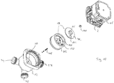
- the centrifugal pump assembly has a motor housing 2, in which an electric drive motor is arranged.
- This has in known manner a stator 4 and a rotor 6, which is arranged on a rotor shaft 8.
- the rotor 6 rotates in a rotor space, which is separated from the stator space in which the stator 4 is arranged by a split tube or a split pot 10. That is, it is a wet-running electric drive motor.
- the motor housing 2 is connected to a pump housing 12, in which a rotatably connected to the rotor shaft 8 impeller 14 rotates.
- an electronics housing 16 is arranged, which includes a control electronics or control device 17 for controlling the electric drive motor in the pump housing 2.
- the electronics housing 16 could also be arranged in a corresponding manner on another side of the stator housing 2.
- a movable valve element 18 is arranged in the pump housing 12.
- This valve element 18 is rotatably mounted on an axis 20 in the interior of the pump housing 12, namely such that the axis of rotation of the valve element 18 is aligned with the axis of rotation X of the impeller 14.
- the axis 20 is rotatably fixed to the bottom of the pump housing 12.
- the valve element 18 is not only rotatable about the axis 20, but by a certain amount in the longitudinal direction X movable. In one direction, this linear mobility is limited by the pump housing 12, against which the valve element 18 abuts with its outer circumference.
- the valve element 18 separates in the pump housing 12 a suction chamber 24 from a pressure chamber 26.
- a suction chamber 24 In the pressure chamber 26 rotates the impeller 14.
- the pressure chamber 26 is connected to the pressure connection or discharge nozzle 27 of the centrifugal pump assembly, which forms the outlet of the centrifugal pump assembly.
- a mechanical coupling between the drive motor and the valve element is provided, wherein in these embodiments, the drive motor can be controlled by the control device 17 in two different operating modes or operating modes.
- a first mode which corresponds to the normal operation of the circulating pump unit
- the drive motor rotates in a conventional manner with a desired, in particular adjustable by the control device 17, speed.
- the second operating mode the drive motor is activated in open-loop operation, so that the rotor can be turned stepwise in individual angular steps predetermined by the control device 17, which are smaller than 360 °.
- the drive motor in the manner of a stepping motor can be moved in individual steps, which is used in these embodiments, the valve element targeted to move in small angular increments in a defined position, as will be described below.
- a mixing valve as it can be used for example for temperature adjustment for underfloor heating.
- the motor housing 2 with the electronics housing 16 corresponds to the embodiment described above.
- the pump housing 12 has, in addition to the pressure port 27, two suction-side ports 32 and 34 which open at the bottom of the pump housing 12 in inputs 28 and 30, which are located in a plane transverse to the axis of rotation X.
- the valve element 18 is drum-shaped and consists of a cup-shaped lower part 76, which is closed on its side facing the impeller 14 by a cover 78. In the central region of the lid 78, a suction opening 36 is formed. The suction opening 36 is in engagement with the suction mouth 38 of the impeller 14.
- the valve element 18 is rotatably mounted on an axle 20, which is arranged in the bottom of the pump housing 12. The axis of rotation of the valve element 18 corresponds to the axis of rotation X of the rotor shaft 8.
- the valve element 18 is also axially displaceable along the axis X and is by a spring 48 in the in Fig.
- the valve element 18 As an axial stop acting in the released position, the front end of the rotor shaft 8, which is designed as a coupling 108.
- the clutch 108 engages with a counter-coupling 110, which is arranged non-rotatably on the valve element 18 in engagement.
- the coupling 108 has tapered coupling surfaces, which essentially describe a sawtooth profile along a circumferential line in such a way that torque transmission from the coupling 108 to the counter-coupling 110 is possible only in one direction of rotation is, namely in the direction of rotation A in Fig.
- the direction of rotation B is the direction of rotation in which the pump unit is driven in normal operation.
- the direction of rotation A is used for targeted adjustment of the valve element 18. That is, here is a direction of rotation dependent coupling is formed.
- the mating coupling 110 disengages from the coupling 108 by the pressure in the pressure chamber 26. If the pressure in the pressure chamber 26 increases, a pressure force acting on the cover 78, which is opposite to the spring force of the spring 48 and exceeds this, so that the valve element 18 is pressed into the applied position, which in Fig. 4 is shown.
- the lower part 76 is located on the bottom side of the pump housing 12, so that on the one hand, the valve element 18 is frictionally held and on the other a tight contact is achieved, which seals the pressure and suction side in the manner described below against each other.
- the suction port 32 opens at the inlet 28 and the suction port 34 opens at the inlet 30 in the bottom of the pump housing 12 in the interior, that is, the suction chamber 24 into it.
- the lower part 76 of the valve element 18 has in its bottom an arcuate opening 112, which extends substantially over 90 °.
- Fig. 6 shows a first switching position in which the opening 112 covers only the input 30, so that a flow path is given only from the suction port 34 to the suction port 36 and thus to the suction port 38 of the impeller 14.
- the second input 28 is sealed by the voltage applied in its peripheral region bottom of the valve element 18.
- Fig. 8 shows the second switching position in which the opening 112 covers only the input 28 while the input 30 is closed.
- FIG. 7 now shows an intermediate position in which the opening 112 covers both inputs 28 and 30, the input 30 is only partially released.
- a mixing ratio between the flows from the inputs 28 and 30 can be changed.
- about the stepwise adjustment of the rotor shaft 8 and the valve element 18 can be adjusted in small steps to change the mixing ratio.
- Such functionality may, for example, be used in a hydraulic system as shown in FIG. There, the centrifugal pump assembly with the integrated valve, as described above, characterized by the dashed line 1.
- the hydraulic circuit has a heat source 114 in the form of, for example, a gas boiler, whose outlet opens into, for example, the suction port 34 of the pump housing 12.
- a floor heating circuit 116 connects to the pressure connection 27 of the centrifugal pump assembly 1, the return of which is connected both to the inlet of the heat source 114 and to the suction connection 32 of the centrifugal pump unit.
- a further heating circuit 120 can be supplied with a heat carrier, which has the output-side temperature of the heat source 114.
- the floor heating circuit 116 can be controlled in its flow temperature in such a way that cold water from the return to the hot water on the output side of the heat source 114 is mixed, whereby by changing the opening ratios of the inputs 28 and 30 in the manner described above, the mixing ratio Rotation of the valve element 18h can be changed.
- the second embodiment according to Fig. 10 to 19 shows a centrifugal pump unit, which in addition to the above-described mixer functionality nor a switching functionality for having additional supply of a secondary heat exchanger for domestic water heating.
- valve element 18i in this embodiment, is the same as in the ninth embodiment.
- valve element 18i in addition to the opening 112 on a passage 122 which extends from an opening 124 in the lid 78i to an opening in the bottom of the lower part 76i and thus connects the two axial ends of the valve element 18i together.
- the valve element 18i is still an only to the bottom, that is, to the bottom of the lower part 76i and thus open to the suction chamber 24 toward arcuate bridging opening 126 is formed, which is closed to the pressure chamber 26 through the lid 78i.
- the pump housing 12 has, in addition to the pressure port 27 and the two previously described suction ports 34 and 32, a further port 128.
- the port 128 opens into an inlet 130 in the bottom of Umisselzpumpenaggregates 12 in addition to the inputs 28 and 30 in the suction chamber 24 into it.
- the lid 78i of the valve element 18i is shown partially opened to illustrate the position of the underlying openings.
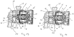
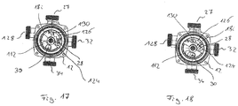
- Fig. 15 shows a first switching position, in which the opening 112 opposite the input 30, so that a flow connection from the suction port 34 to the suction port 38 of the impeller 14 is made. In the switching position according to Fig.
- the opening 112 is located above the inlet 130 so that a flow connection is created from the connection 128 to the suction opening 36 and via this into the suction mouth 38 of the impeller 14.
- the opening 112 is above the entrance 30, so in turn, a flow connection from the suction port 34th given to the suction mouth 38 of the impeller 14.
- a partial overlap of the opening 124 and the through hole 122 with the input 28 takes place, so that a connection between the pressure chamber 26 and the suction port 32 is made, which acts as a pressure port.
- the bypass opening 126 concurrently covers the input 130 and a portion of the input 28, so that also a connection from the terminal 128 via the input 130, the bypass opening 126 and the input 28 to the terminal 32 is provided.
- Fig. 18 shows a fourth switching position in which the passageway 122 completely covers the input 28, so that the terminal 32 is connected via the passage 122 and the opening 124 with the pressure chamber 26. At the same time, the bridging opening 126 only covers the entrance 130. The opening 112 also covers the entrance 30.
- the heating system in turn has a primary heat exchanger or a heat source 114, which may be, for example, a gas boiler.
- a first heating circuit 120 On the output side of the flow path is in a first heating circuit 120, which may be formed for example by conventional radiators or radiators.
- a flow path branches off to a secondary heat exchanger 56 for heating service water.
- the heating system further includes a floor heating circuit 116. The returns of the heating circuit 120 and the floor heating circuit 116 open into the suction port 34 on the pump housing 12. The return from the secondary heat exchanger 56 opens into the port 128, which, as will be described below, offers two functionalities.
- the connection 32 of the pump housing 12 is connected to the flow of the floor heating circuit 116.
- the impeller 14 promotes liquid from the suction port 34 via the pressure port 27 through the heat source 140 and the heating circuit 120 and back to the suction port 34.
- the valve element 18i in the second switching position which in Fig. 16 is shown, the plant is switched to domestic water operation, in this state, the pump assembly or the impeller 14 promotes liquid from the port 128, which serves as a suction port, through the pressure port 27, via the heat source 114 through the secondary heat exchanger 56 and back to the terminal 128.
- the valve element 18i in the third switching position which in Fig. 17 is shown, the underfloor heating circuit 116 is additionally supplied.
- the water flows into the suction mouth 38 of the impeller 14 and is conveyed via the pressure connection 27 via the heat source 114 in the manner described by the first heating circuit 120.
- the liquid emerges on the output side of the impeller 14 from the pressure chamber 26 into the opening 124 and through the through-passage 122 and thus flows to the connection 32 and via this into the underfloor heating circuit 116.
- FIG. 17 The switch position shown flows simultaneously via the bridging opening 126 liquid via the terminal 128 and the input 130 into the terminal 32. That is, here water flows through the heat source 114 through the secondary heat exchanger 26 and the terminal 128 to the terminal 32. Since in this heating operation on Secondary heat exchanger 56 is removed substantially no heat, so the port 32 hot water in addition to the cold water, which flows from the pressure chamber 26 via the passage 122 to the port 32, admixed. By changing the Opening degree over the valve position 18i, the amount of mixed warm water at port 32 can be varied.
- Fig. 18 shows a switching position in which the admixture is turned off and the terminal 32 is exclusively in communication with the pressure chamber 26 directly.
- the rotor 6 is preferably initially positioned when the second change of mode is performed again in such a way that the control device 17 rotates the rotor 6 by appropriate control of the stator 4 is not quite up to the stored angular position rotates, sondem preferably shortly before stops. Ie.
- the rotor 6 is rotated into a previously stored angular position or into an angular position which is slightly ahead of the last stored angular position in the direction of rotation.
- the rotor can be rotated together with the valve element 18, 18i in a desired second angular position, wherein the control device 17 controls the stator 6 so that the rotor 6 rotates in this second mode exactly to the desired angle.
- the counter-coupling 110 is taken over the clutch 108, so that the valve element 18, 18i is then rotated to the desired angular position.
- the rotor 6 is stopped and the control device 17 switches back to the first mode or the first operating mode and starts the rotor 6 in the opposite direction of rotation, so that the clutch 108 can disengage from the counter-coupling 110 and the rest by the axial Displacement of the valve element 18, 18i by the pressure generated in the pressure chamber 26, the clutch 108 and the counter-coupling 110 completely disengage and the valve element 18, 18i is held by engagement with the bottom of the pump housing 12 in the achieved switching position.
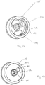
- the coupling 108 has two bevels 132 which extend from two end edges 134 which extend substantially diametrically with respect to the axis of rotation X.
- engagement surfaces 136 which essentially run in a plane which is spanned by the rotation axis X and a diameter line to this rotation axis X extend.
- the counter-coupling 110 has a web-shaped projection 138 extending in the diameter direction with respect to the axis of rotation X, which protrudes in the axial direction and has two substantially mutually parallel side surfaces, which in turn extend in planes which in the Essentially spanned by the diameter line and the axis of rotation X or parallel to these axes.
- a fixed axis extends in the direction of the axis of rotation X in the interior of the pump housing 12.
- the valve element 18, 18i is rotatably mounted.
- the axis 20 engages in a blind hole 140 in the bottom of the valve element 18, 18i, which faces away from the impeller 14, a.
- a seal 142 is arranged, which is on the outer circumference of the axis 20 slidably in abutment. The seal 142 seals the interior of the blind hole 140 to the outside.
- a lubricant can be arranged to lubricate the slide bearing permanently or pre-lubricate.
- the seal 142 allows a slight leakage, so that long-term liquid from the pump housing 12, in particular water, can penetrate into the interior of the blind hole 140 and there the lubrication between the valve element 18, 18i and axis 20 is used.
- the seal 142 is designed so that particles and impurities are retained so that a permanent ease of storage is ensured.
- the axis 20 also has a the impeller 14 facing circumferential shoulder 144, at which the axis 20 tapers. Between this shoulder 144 and the bottom of the blind hole 140, which is located on the impeller 14 facing the end, the spring 48 is supported, whose function has already been described above. In this way, the spring 48 is completely located in the interior of the blind hole 140, which defines the storage space, so that the spring 48 is protected from contamination from the pumped by the pump unit fluid.
- valve element 18, 18i could also be used together with the valve element 18, 18i, if this would be hydraulically coupled instead of the described mechanical coupling 108, 110. If the said coupling 108, 110 is omitted, the valve element could instead be rotated by the flow rotated by the impeller 14 in the pressure space 26 by acting on the cover 78, 78i. In addition, in such an embodiment could be stops which define the switching positions of the valve element 18, 18i. The movement between these switching positions could then be achieved by reversing the direction of rotation of the impeller 14.
- the pump housing 12 which also serves as a valve housing, integrally formed.
- the pump housing 12 could also be composed of several individual parts or could be designed in several parts.
- a pump housing separate from the valve housing could be provided, wherein the valve housing accommodates the valve element 18, 18i, while the pressure chamber 26 is formed in the pump housing.
Landscapes
- Engineering & Computer Science (AREA)
- Mechanical Engineering (AREA)
- General Engineering & Computer Science (AREA)
- Physics & Mathematics (AREA)
- Fluid Mechanics (AREA)
- Structures Of Non-Positive Displacement Pumps (AREA)
Priority Applications (2)
| Application Number | Priority Date | Filing Date | Title |
|---|---|---|---|
| EP17160841.7A EP3376039B1 (fr) | 2017-03-14 | 2017-03-14 | Groupe pompe centrifuge |
| PCT/EP2018/056099 WO2018166979A1 (fr) | 2017-03-14 | 2018-03-12 | Ensemble pompe centrifuge |
Applications Claiming Priority (1)
| Application Number | Priority Date | Filing Date | Title |
|---|---|---|---|
| EP17160841.7A EP3376039B1 (fr) | 2017-03-14 | 2017-03-14 | Groupe pompe centrifuge |
Publications (2)
| Publication Number | Publication Date |
|---|---|
| EP3376039A1 true EP3376039A1 (fr) | 2018-09-19 |
| EP3376039B1 EP3376039B1 (fr) | 2021-08-04 |
Family
ID=58347149
Family Applications (1)
| Application Number | Title | Priority Date | Filing Date |
|---|---|---|---|
| EP17160841.7A Active EP3376039B1 (fr) | 2017-03-14 | 2017-03-14 | Groupe pompe centrifuge |
Country Status (2)
| Country | Link |
|---|---|
| EP (1) | EP3376039B1 (fr) |
| WO (1) | WO2018166979A1 (fr) |
Citations (5)
| Publication number | Priority date | Publication date | Assignee | Title |
|---|---|---|---|---|
| CH463896A (de) * | 1963-09-21 | 1968-10-15 | Louis Dipl Ing Siber | Misch- und Temperaturregelvorrichtung in einem Gehäuse mit mehreren Anschluss-Stutzen für Warmwasserheizungs- und -bereitungsanlagen |
| DE1928839A1 (de) * | 1968-06-17 | 1969-12-18 | Heinrich Gieselmann | Umwaelzpumpe |
| FR2074692A2 (fr) * | 1970-01-19 | 1971-10-08 | Materiel Telephonique | Pompe-vanne, en particulier pour le chaffage central |
| DE9013992U1 (de) | 1990-10-08 | 1991-10-24 | Grundfos International A/S, Bjerringbro | Motorpumpenaggregat für Kreislaufsysteme mit zwei parallelen Kreisläufen |
| US5924432A (en) * | 1995-10-17 | 1999-07-20 | Whirlpool Corporation | Dishwasher having a wash liquid recirculation system |
Family Cites Families (2)
| Publication number | Priority date | Publication date | Assignee | Title |
|---|---|---|---|---|
| FR2646212B1 (fr) * | 1989-04-21 | 1994-04-15 | Icf | Appareil de circulation et de distribution de fluide |
| DE10207653C1 (de) * | 2002-02-22 | 2003-09-25 | Gpm Geraete Und Pumpenbau Gmbh | Elektrische Kühlmittelpumpe mit integriertem Ventil, sowie Verfahren zu dessen Steuerung |
-
2017
- 2017-03-14 EP EP17160841.7A patent/EP3376039B1/fr active Active
-
2018
- 2018-03-12 WO PCT/EP2018/056099 patent/WO2018166979A1/fr not_active Ceased
Patent Citations (5)
| Publication number | Priority date | Publication date | Assignee | Title |
|---|---|---|---|---|
| CH463896A (de) * | 1963-09-21 | 1968-10-15 | Louis Dipl Ing Siber | Misch- und Temperaturregelvorrichtung in einem Gehäuse mit mehreren Anschluss-Stutzen für Warmwasserheizungs- und -bereitungsanlagen |
| DE1928839A1 (de) * | 1968-06-17 | 1969-12-18 | Heinrich Gieselmann | Umwaelzpumpe |
| FR2074692A2 (fr) * | 1970-01-19 | 1971-10-08 | Materiel Telephonique | Pompe-vanne, en particulier pour le chaffage central |
| DE9013992U1 (de) | 1990-10-08 | 1991-10-24 | Grundfos International A/S, Bjerringbro | Motorpumpenaggregat für Kreislaufsysteme mit zwei parallelen Kreisläufen |
| US5924432A (en) * | 1995-10-17 | 1999-07-20 | Whirlpool Corporation | Dishwasher having a wash liquid recirculation system |
Also Published As
| Publication number | Publication date |
|---|---|
| WO2018166979A1 (fr) | 2018-09-20 |
| EP3376039B1 (fr) | 2021-08-04 |
Similar Documents
| Publication | Publication Date | Title |
|---|---|---|
| WO2018167043A1 (fr) | Groupe motopompe | |
| WO2018166967A1 (fr) | Ensemble pompe centrifuge | |
| DE10323900A1 (de) | Mehrwegeventil für ein Fahrzeug-Kühl/Heiz-System | |
| EP3376037B1 (fr) | Groupe pompe centrifuge | |
| EP3376038B1 (fr) | Groupe motopompe | |
| EP3540233A1 (fr) | Groupe pompe centrifuge avec valve rotative | |
| EP3376051B1 (fr) | Groupe motopompe | |
| EP3267042B1 (fr) | Groupe motopompe | |
| DE102010050605A1 (de) | Vorrichtung zur Regelung eines Kühlmittelstroms sowie Kühlsystem | |
| WO2018167047A1 (fr) | Ensemble pompe centrifuge | |
| EP2818726A1 (fr) | Pompe centrifuge avec roue à aubes déplaçable axialement pour l'alimentation de circuits différents | |
| EP3325859B1 (fr) | Module de répartition d'un agent de refroidissement pour un circuit de refroidissement | |
| EP3376040B1 (fr) | Groupe motopompe | |
| EP3438556A1 (fr) | Dispositif de mélange, système de chauffage avec dispositif de mélange et procédé | |
| DE102020207028A1 (de) | Pumpeneinheit | |
| EP3376039B1 (fr) | Groupe pompe centrifuge | |
| EP1293678B1 (fr) | Rouet de pompe avec fonction de clapet anti-retour intégré | |
| EP3376052B1 (fr) | Groupe pompe centrifuge | |
| DE3006386A1 (de) | Drehzahlabhaengig steuerbares rotations-ventil | |
| WO2012089499A1 (fr) | Soupape de commande de débits volumétriques | |
| DE102012220450B4 (de) | Ventilbaugruppe, Kühlmittelbaugruppe und Motorbaugruppe | |
| EP3392505A1 (fr) | Dispositif mitigeur pour un système hydraulique ainsi que système de refroidissement à huile et installation de compresseur pourvu d'un tel dispositif mitigeur | |
| EP3376131A1 (fr) | Station d'appartement | |
| DE102010049059B4 (de) | Drehmomentübertragungseinrichtung | |
| DE102013202761A1 (de) | Thermostatventil |
Legal Events
| Date | Code | Title | Description |
|---|---|---|---|
| PUAI | Public reference made under article 153(3) epc to a published international application that has entered the european phase |
Free format text: ORIGINAL CODE: 0009012 |
|
| STAA | Information on the status of an ep patent application or granted ep patent |
Free format text: STATUS: THE APPLICATION HAS BEEN PUBLISHED |
|
| AK | Designated contracting states |
Kind code of ref document: A1 Designated state(s): AL AT BE BG CH CY CZ DE DK EE ES FI FR GB GR HR HU IE IS IT LI LT LU LV MC MK MT NL NO PL PT RO RS SE SI SK SM TR |
|
| AX | Request for extension of the european patent |
Extension state: BA ME |
|
| STAA | Information on the status of an ep patent application or granted ep patent |
Free format text: STATUS: REQUEST FOR EXAMINATION WAS MADE |
|
| 17P | Request for examination filed |
Effective date: 20190315 |
|
| RBV | Designated contracting states (corrected) |
Designated state(s): AL AT BE BG CH CY CZ DE DK EE ES FI FR GB GR HR HU IE IS IT LI LT LU LV MC MK MT NL NO PL PT RO RS SE SI SK SM TR |
|
| STAA | Information on the status of an ep patent application or granted ep patent |
Free format text: STATUS: EXAMINATION IS IN PROGRESS |
|
| 17Q | First examination report despatched |
Effective date: 20200702 |
|
| GRAP | Despatch of communication of intention to grant a patent |
Free format text: ORIGINAL CODE: EPIDOSNIGR1 |
|
| STAA | Information on the status of an ep patent application or granted ep patent |
Free format text: STATUS: GRANT OF PATENT IS INTENDED |
|
| INTG | Intention to grant announced |
Effective date: 20210315 |
|
| GRAS | Grant fee paid |
Free format text: ORIGINAL CODE: EPIDOSNIGR3 |
|
| GRAA | (expected) grant |
Free format text: ORIGINAL CODE: 0009210 |
|
| STAA | Information on the status of an ep patent application or granted ep patent |
Free format text: STATUS: THE PATENT HAS BEEN GRANTED |
|
| AK | Designated contracting states |
Kind code of ref document: B1 Designated state(s): AL AT BE BG CH CY CZ DE DK EE ES FI FR GB GR HR HU IE IS IT LI LT LU LV MC MK MT NL NO PL PT RO RS SE SI SK SM TR |
|
| REG | Reference to a national code |
Ref country code: GB Ref legal event code: FG4D Free format text: NOT ENGLISH |
|
| REG | Reference to a national code |
Ref country code: AT Ref legal event code: REF Ref document number: 1417244 Country of ref document: AT Kind code of ref document: T Effective date: 20210815 |
|
| REG | Reference to a national code |
Ref country code: CH Ref legal event code: EP |
|
| REG | Reference to a national code |
Ref country code: DE Ref legal event code: R096 Ref document number: 502017011070 Country of ref document: DE |
|
| REG | Reference to a national code |
Ref country code: IE Ref legal event code: FG4D Free format text: LANGUAGE OF EP DOCUMENT: GERMAN |
|
| REG | Reference to a national code |
Ref country code: LT Ref legal event code: MG9D |
|
| REG | Reference to a national code |
Ref country code: NL Ref legal event code: MP Effective date: 20210804 |
|
| PG25 | Lapsed in a contracting state [announced via postgrant information from national office to epo] |
Ref country code: LT Free format text: LAPSE BECAUSE OF FAILURE TO SUBMIT A TRANSLATION OF THE DESCRIPTION OR TO PAY THE FEE WITHIN THE PRESCRIBED TIME-LIMIT Effective date: 20210804 Ref country code: BG Free format text: LAPSE BECAUSE OF FAILURE TO SUBMIT A TRANSLATION OF THE DESCRIPTION OR TO PAY THE FEE WITHIN THE PRESCRIBED TIME-LIMIT Effective date: 20211104 Ref country code: ES Free format text: LAPSE BECAUSE OF FAILURE TO SUBMIT A TRANSLATION OF THE DESCRIPTION OR TO PAY THE FEE WITHIN THE PRESCRIBED TIME-LIMIT Effective date: 20210804 Ref country code: FI Free format text: LAPSE BECAUSE OF FAILURE TO SUBMIT A TRANSLATION OF THE DESCRIPTION OR TO PAY THE FEE WITHIN THE PRESCRIBED TIME-LIMIT Effective date: 20210804 Ref country code: HR Free format text: LAPSE BECAUSE OF FAILURE TO SUBMIT A TRANSLATION OF THE DESCRIPTION OR TO PAY THE FEE WITHIN THE PRESCRIBED TIME-LIMIT Effective date: 20210804 Ref country code: PT Free format text: LAPSE BECAUSE OF FAILURE TO SUBMIT A TRANSLATION OF THE DESCRIPTION OR TO PAY THE FEE WITHIN THE PRESCRIBED TIME-LIMIT Effective date: 20211206 Ref country code: NO Free format text: LAPSE BECAUSE OF FAILURE TO SUBMIT A TRANSLATION OF THE DESCRIPTION OR TO PAY THE FEE WITHIN THE PRESCRIBED TIME-LIMIT Effective date: 20211104 Ref country code: SE Free format text: LAPSE BECAUSE OF FAILURE TO SUBMIT A TRANSLATION OF THE DESCRIPTION OR TO PAY THE FEE WITHIN THE PRESCRIBED TIME-LIMIT Effective date: 20210804 Ref country code: RS Free format text: LAPSE BECAUSE OF FAILURE TO SUBMIT A TRANSLATION OF THE DESCRIPTION OR TO PAY THE FEE WITHIN THE PRESCRIBED TIME-LIMIT Effective date: 20210804 |
|
| PG25 | Lapsed in a contracting state [announced via postgrant information from national office to epo] |
Ref country code: PL Free format text: LAPSE BECAUSE OF FAILURE TO SUBMIT A TRANSLATION OF THE DESCRIPTION OR TO PAY THE FEE WITHIN THE PRESCRIBED TIME-LIMIT Effective date: 20210804 Ref country code: LV Free format text: LAPSE BECAUSE OF FAILURE TO SUBMIT A TRANSLATION OF THE DESCRIPTION OR TO PAY THE FEE WITHIN THE PRESCRIBED TIME-LIMIT Effective date: 20210804 Ref country code: GR Free format text: LAPSE BECAUSE OF FAILURE TO SUBMIT A TRANSLATION OF THE DESCRIPTION OR TO PAY THE FEE WITHIN THE PRESCRIBED TIME-LIMIT Effective date: 20211105 |
|
| PG25 | Lapsed in a contracting state [announced via postgrant information from national office to epo] |
Ref country code: NL Free format text: LAPSE BECAUSE OF FAILURE TO SUBMIT A TRANSLATION OF THE DESCRIPTION OR TO PAY THE FEE WITHIN THE PRESCRIBED TIME-LIMIT Effective date: 20210804 |
|
| PG25 | Lapsed in a contracting state [announced via postgrant information from national office to epo] |
Ref country code: DK Free format text: LAPSE BECAUSE OF FAILURE TO SUBMIT A TRANSLATION OF THE DESCRIPTION OR TO PAY THE FEE WITHIN THE PRESCRIBED TIME-LIMIT Effective date: 20210804 |
|
| PGFP | Annual fee paid to national office [announced via postgrant information from national office to epo] |
Ref country code: GB Payment date: 20220324 Year of fee payment: 6 Ref country code: DE Payment date: 20220323 Year of fee payment: 6 |
|
| REG | Reference to a national code |
Ref country code: DE Ref legal event code: R097 Ref document number: 502017011070 Country of ref document: DE |
|
| PG25 | Lapsed in a contracting state [announced via postgrant information from national office to epo] |
Ref country code: SM Free format text: LAPSE BECAUSE OF FAILURE TO SUBMIT A TRANSLATION OF THE DESCRIPTION OR TO PAY THE FEE WITHIN THE PRESCRIBED TIME-LIMIT Effective date: 20210804 Ref country code: SK Free format text: LAPSE BECAUSE OF FAILURE TO SUBMIT A TRANSLATION OF THE DESCRIPTION OR TO PAY THE FEE WITHIN THE PRESCRIBED TIME-LIMIT Effective date: 20210804 Ref country code: RO Free format text: LAPSE BECAUSE OF FAILURE TO SUBMIT A TRANSLATION OF THE DESCRIPTION OR TO PAY THE FEE WITHIN THE PRESCRIBED TIME-LIMIT Effective date: 20210804 Ref country code: EE Free format text: LAPSE BECAUSE OF FAILURE TO SUBMIT A TRANSLATION OF THE DESCRIPTION OR TO PAY THE FEE WITHIN THE PRESCRIBED TIME-LIMIT Effective date: 20210804 Ref country code: CZ Free format text: LAPSE BECAUSE OF FAILURE TO SUBMIT A TRANSLATION OF THE DESCRIPTION OR TO PAY THE FEE WITHIN THE PRESCRIBED TIME-LIMIT Effective date: 20210804 Ref country code: AL Free format text: LAPSE BECAUSE OF FAILURE TO SUBMIT A TRANSLATION OF THE DESCRIPTION OR TO PAY THE FEE WITHIN THE PRESCRIBED TIME-LIMIT Effective date: 20210804 |
|
| PGFP | Annual fee paid to national office [announced via postgrant information from national office to epo] |
Ref country code: FR Payment date: 20220322 Year of fee payment: 6 |
|
| PLBE | No opposition filed within time limit |
Free format text: ORIGINAL CODE: 0009261 |
|
| STAA | Information on the status of an ep patent application or granted ep patent |
Free format text: STATUS: NO OPPOSITION FILED WITHIN TIME LIMIT |
|
| 26N | No opposition filed |
Effective date: 20220506 |
|
| PG25 | Lapsed in a contracting state [announced via postgrant information from national office to epo] |
Ref country code: IT Free format text: LAPSE BECAUSE OF FAILURE TO SUBMIT A TRANSLATION OF THE DESCRIPTION OR TO PAY THE FEE WITHIN THE PRESCRIBED TIME-LIMIT Effective date: 20210804 |
|
| PG25 | Lapsed in a contracting state [announced via postgrant information from national office to epo] |
Ref country code: SI Free format text: LAPSE BECAUSE OF FAILURE TO SUBMIT A TRANSLATION OF THE DESCRIPTION OR TO PAY THE FEE WITHIN THE PRESCRIBED TIME-LIMIT Effective date: 20210804 |
|
| REG | Reference to a national code |
Ref country code: DE Ref legal event code: R082 Ref document number: 502017011070 Country of ref document: DE |
|
| PG25 | Lapsed in a contracting state [announced via postgrant information from national office to epo] |
Ref country code: MC Free format text: LAPSE BECAUSE OF FAILURE TO SUBMIT A TRANSLATION OF THE DESCRIPTION OR TO PAY THE FEE WITHIN THE PRESCRIBED TIME-LIMIT Effective date: 20210804 |
|
| REG | Reference to a national code |
Ref country code: CH Ref legal event code: PL |
|
| REG | Reference to a national code |
Ref country code: BE Ref legal event code: MM Effective date: 20220331 |
|
| PG25 | Lapsed in a contracting state [announced via postgrant information from national office to epo] |
Ref country code: LU Free format text: LAPSE BECAUSE OF NON-PAYMENT OF DUE FEES Effective date: 20220314 Ref country code: LI Free format text: LAPSE BECAUSE OF NON-PAYMENT OF DUE FEES Effective date: 20220331 Ref country code: IE Free format text: LAPSE BECAUSE OF NON-PAYMENT OF DUE FEES Effective date: 20220314 Ref country code: CH Free format text: LAPSE BECAUSE OF NON-PAYMENT OF DUE FEES Effective date: 20220331 |
|
| PG25 | Lapsed in a contracting state [announced via postgrant information from national office to epo] |
Ref country code: BE Free format text: LAPSE BECAUSE OF NON-PAYMENT OF DUE FEES Effective date: 20220331 |
|
| REG | Reference to a national code |
Ref country code: AT Ref legal event code: MM01 Ref document number: 1417244 Country of ref document: AT Kind code of ref document: T Effective date: 20220314 |
|
| PG25 | Lapsed in a contracting state [announced via postgrant information from national office to epo] |
Ref country code: AT Free format text: LAPSE BECAUSE OF NON-PAYMENT OF DUE FEES Effective date: 20220314 |
|
| REG | Reference to a national code |
Ref country code: DE Ref legal event code: R119 Ref document number: 502017011070 Country of ref document: DE |
|
| GBPC | Gb: european patent ceased through non-payment of renewal fee |
Effective date: 20230314 |
|
| PG25 | Lapsed in a contracting state [announced via postgrant information from national office to epo] |
Ref country code: GB Free format text: LAPSE BECAUSE OF NON-PAYMENT OF DUE FEES Effective date: 20230314 |
|
| PG25 | Lapsed in a contracting state [announced via postgrant information from national office to epo] |
Ref country code: GB Free format text: LAPSE BECAUSE OF NON-PAYMENT OF DUE FEES Effective date: 20230314 Ref country code: FR Free format text: LAPSE BECAUSE OF NON-PAYMENT OF DUE FEES Effective date: 20230331 Ref country code: DE Free format text: LAPSE BECAUSE OF NON-PAYMENT OF DUE FEES Effective date: 20231003 |
|
| PG25 | Lapsed in a contracting state [announced via postgrant information from national office to epo] |
Ref country code: HU Free format text: LAPSE BECAUSE OF FAILURE TO SUBMIT A TRANSLATION OF THE DESCRIPTION OR TO PAY THE FEE WITHIN THE PRESCRIBED TIME-LIMIT; INVALID AB INITIO Effective date: 20170314 |
|
| PG25 | Lapsed in a contracting state [announced via postgrant information from national office to epo] |
Ref country code: MK Free format text: LAPSE BECAUSE OF FAILURE TO SUBMIT A TRANSLATION OF THE DESCRIPTION OR TO PAY THE FEE WITHIN THE PRESCRIBED TIME-LIMIT Effective date: 20210804 Ref country code: CY Free format text: LAPSE BECAUSE OF FAILURE TO SUBMIT A TRANSLATION OF THE DESCRIPTION OR TO PAY THE FEE WITHIN THE PRESCRIBED TIME-LIMIT Effective date: 20210804 |
|
| PG25 | Lapsed in a contracting state [announced via postgrant information from national office to epo] |
Ref country code: MT Free format text: LAPSE BECAUSE OF FAILURE TO SUBMIT A TRANSLATION OF THE DESCRIPTION OR TO PAY THE FEE WITHIN THE PRESCRIBED TIME-LIMIT Effective date: 20210804 |
|
| PG25 | Lapsed in a contracting state [announced via postgrant information from national office to epo] |
Ref country code: TR Free format text: LAPSE BECAUSE OF FAILURE TO SUBMIT A TRANSLATION OF THE DESCRIPTION OR TO PAY THE FEE WITHIN THE PRESCRIBED TIME-LIMIT Effective date: 20210804 |