EP3376083A1 - Actionneur de soupape - Google Patents
Actionneur de soupape Download PDFInfo
- Publication number
- EP3376083A1 EP3376083A1 EP16864130.6A EP16864130A EP3376083A1 EP 3376083 A1 EP3376083 A1 EP 3376083A1 EP 16864130 A EP16864130 A EP 16864130A EP 3376083 A1 EP3376083 A1 EP 3376083A1
- Authority
- EP
- European Patent Office
- Prior art keywords
- valve
- cylinder
- disc
- output disc
- link
- Prior art date
- Legal status (The legal status is an assumption and is not a legal conclusion. Google has not performed a legal analysis and makes no representation as to the accuracy of the status listed.)
- Granted
Links
Images


Classifications
-
- F—MECHANICAL ENGINEERING; LIGHTING; HEATING; WEAPONS; BLASTING
- F16—ENGINEERING ELEMENTS AND UNITS; GENERAL MEASURES FOR PRODUCING AND MAINTAINING EFFECTIVE FUNCTIONING OF MACHINES OR INSTALLATIONS; THERMAL INSULATION IN GENERAL
- F16K—VALVES; TAPS; COCKS; ACTUATING-FLOATS; DEVICES FOR VENTING OR AERATING
- F16K31/00—Actuating devices; Operating means; Releasing devices
- F16K31/44—Mechanical actuating means
-
- F—MECHANICAL ENGINEERING; LIGHTING; HEATING; WEAPONS; BLASTING
- F04—POSITIVE - DISPLACEMENT MACHINES FOR LIQUIDS; PUMPS FOR LIQUIDS OR ELASTIC FLUIDS
- F04B—POSITIVE-DISPLACEMENT MACHINES FOR LIQUIDS; PUMPS
- F04B39/00—Component parts, details, or accessories, of pumps or pumping systems specially adapted for elastic fluids, not otherwise provided for in, or of interest apart from, groups F04B25/00 - F04B37/00
- F04B39/10—Adaptations or arrangements of distribution members
- F04B39/1013—Adaptations or arrangements of distribution members the members being of the poppet valve type
-
- F—MECHANICAL ENGINEERING; LIGHTING; HEATING; WEAPONS; BLASTING
- F16—ENGINEERING ELEMENTS AND UNITS; GENERAL MEASURES FOR PRODUCING AND MAINTAINING EFFECTIVE FUNCTIONING OF MACHINES OR INSTALLATIONS; THERMAL INSULATION IN GENERAL
- F16K—VALVES; TAPS; COCKS; ACTUATING-FLOATS; DEVICES FOR VENTING OR AERATING
- F16K1/00—Lift valves or globe valves, i.e. cut-off apparatus with closure members having at least a component of their opening and closing motion perpendicular to the closing faces
-
- F—MECHANICAL ENGINEERING; LIGHTING; HEATING; WEAPONS; BLASTING
- F16—ENGINEERING ELEMENTS AND UNITS; GENERAL MEASURES FOR PRODUCING AND MAINTAINING EFFECTIVE FUNCTIONING OF MACHINES OR INSTALLATIONS; THERMAL INSULATION IN GENERAL
- F16K—VALVES; TAPS; COCKS; ACTUATING-FLOATS; DEVICES FOR VENTING OR AERATING
- F16K1/00—Lift valves or globe valves, i.e. cut-off apparatus with closure members having at least a component of their opening and closing motion perpendicular to the closing faces
- F16K1/16—Lift valves or globe valves, i.e. cut-off apparatus with closure members having at least a component of their opening and closing motion perpendicular to the closing faces with pivoted closure-members
- F16K1/18—Lift valves or globe valves, i.e. cut-off apparatus with closure members having at least a component of their opening and closing motion perpendicular to the closing faces with pivoted closure-members with pivoted discs or flaps
- F16K1/20—Lift valves or globe valves, i.e. cut-off apparatus with closure members having at least a component of their opening and closing motion perpendicular to the closing faces with pivoted closure-members with pivoted discs or flaps with axis of rotation arranged externally of valve member
-
- F—MECHANICAL ENGINEERING; LIGHTING; HEATING; WEAPONS; BLASTING
- F16—ENGINEERING ELEMENTS AND UNITS; GENERAL MEASURES FOR PRODUCING AND MAINTAINING EFFECTIVE FUNCTIONING OF MACHINES OR INSTALLATIONS; THERMAL INSULATION IN GENERAL
- F16K—VALVES; TAPS; COCKS; ACTUATING-FLOATS; DEVICES FOR VENTING OR AERATING
- F16K31/00—Actuating devices; Operating means; Releasing devices
- F16K31/02—Actuating devices; Operating means; Releasing devices electric; magnetic
- F16K31/04—Actuating devices; Operating means; Releasing devices electric; magnetic using a motor
- F16K31/047—Actuating devices; Operating means; Releasing devices electric; magnetic using a motor characterised by mechanical means between the motor and the valve, e.g. lost motion means reducing backlash, clutches, brakes or return means
-
- F—MECHANICAL ENGINEERING; LIGHTING; HEATING; WEAPONS; BLASTING
- F16—ENGINEERING ELEMENTS AND UNITS; GENERAL MEASURES FOR PRODUCING AND MAINTAINING EFFECTIVE FUNCTIONING OF MACHINES OR INSTALLATIONS; THERMAL INSULATION IN GENERAL
- F16K—VALVES; TAPS; COCKS; ACTUATING-FLOATS; DEVICES FOR VENTING OR AERATING
- F16K31/00—Actuating devices; Operating means; Releasing devices
- F16K31/12—Actuating devices; Operating means; Releasing devices actuated by fluid
- F16K31/16—Actuating devices; Operating means; Releasing devices actuated by fluid with a mechanism, other than pulling-or pushing-rod, between fluid motor and closure member
Definitions
- the present disclosure relates to a valve actuator.
- Patent Literature 1 Japanese Patent No. 5600760 (Patent Literature 1)).
- a valve actuator described in Patent Literature 1 uses an electric motor as a drive source, and converts rotational movement made by the electric motor into linear movement by using a ball screw to operate a valve plug of a poppet valve at a constant speed with a constant force independently of the stroke.
- Patent Literature 1 Japanese Patent No. 5600760
- an object of the present disclosure is to provide a valve actuator that can achieve both an open/close speed needed to open and close a poppet valve and a shutting force needed to close the valve.
- a valve actuator is a valve actuator that drives opening and closing of a poppet valve and includes a motor and a transmission mechanism that transmits a drive force of the motor to the poppet valve.
- the transmission mechanism includes a booster mechanism, and the booster mechanism is a three-dimensional toggle mechanism that includes a cylinder, an input disc that rotates about an axis in the cylinder, an output disc that reciprocates along an axial direction in the cylinder, and a link that connects the input disc and the output disc.
- the booster mechanism may include a ball joint, and the ball joint may be disposed in the cylinder to be in contact with an inner periphery of the cylinder, and interconnect an outer edge portion of the input disc and one end of the link as well as interconnect an outer edge portion of the output disc and the other end of the link.
- the booster mechanism may include a load limiter that is provided between the output disc and a valve plug of the poppet valve, and that limits a load transmitted from the output disc to a valve seat via the valve plug.
- the booster mechanism may include a stopper that is formed on the inner periphery of the cylinder and that restricts movement of the link, and the stopper may be disposed at an advanced position beyond a position where the link comes in parallel to the axis of the cylinder.
- both an open/close speed needed to open and close a poppet valve and a shutting force needed to close the valve can be achieved.
- a valve actuator 1 is what drives opening and closing of a poppet valve 2 illustrated in Fig. 1 .
- the poppet valve 2 is a valve of a type in which a valve plug moves in a direction at a right angle to a valve seat surface (JIS). This poppet valve 2 is used, for example, to open and close a flow channel for supplying fuel to a rocket engine.
- JIS valve seat surface
- the poppet valve 2 includes a valve housing 4 in which a fluid flow channel 3 is formed, and a valve seat 5 disposed in the middle of the flow channel 3.
- a valve plug 6 which opens and closes the valve seat 5, is disposed.
- the valve plug 6 includes a valve stem 7 as a shaft portion of the valve plug 6, and a umbrella portion 8 attached on a tip end portion of the valve stem 7.
- a reference sign 9a denotes a hole portion provided in an output disc 18, to be described later, for coupling the valve plug 6,
- a reference sign 9b denotes a nut for coupling the valve plug 6,
- a reference sign 10 denotes an aligning mechanism of the valve plug 6, and
- a reference sign 11 denotes bellows.
- the valve actuator 1 includes a motor 12 and a transmission mechanism 13, which transmits a drive force of the motor 12 to the poppet valve 2.
- the motor 12 is a stepping motor, for example.
- the motor 12 provided in the valve actuator 1 is operated by an electric signal transmitted from a power source driver (not illustrated) provided outside of the valve actuator 1 to the motor 12.
- the motor 12 is not limited to a stepping motor and may be a motor other than a stepping motor.
- the transmission mechanism 13 includes a decelerator 14 and a booster mechanism 15.
- the decelerator 14 is a planetary gear mechanism, for example. Rotation of the motor 12 is transmitted to the booster mechanism 15 after the number of rotations is reduced and torque is increased by the decelerator 14.
- the decelerator 14 is not limited to a planetary gear mechanism and may be a general gear transmission, a non-stage transmission, and a transmission of a type using a cam and the like.
- the booster mechanism 15 is a three-dimensional toggle mechanism that includes a cylinder 16, an input disc 17, which rotates about an axis CL in the cylinder 16, the output disc 18, which reciprocates along an axis CL direction in the cylinder 16, and links 19, which connect the input disc 17 and the output disc 18.
- the input disc 17 is coupled with an output shaft of the decelerator 14, and the output disc 18 is coupled with the valve plug 6 of the poppet valve 2.
- the input disc 17 is capable of rotating about the axis CL of the cylinder 16 while incapable of reciprocating in the axis CL direction.
- the output disc 18 is incapable of rotating about the axis CL of the cylinder 16 while capable of reciprocating in the axis CL direction.
- the input disc 17 and the output disc 18 are formed in circular shapes; however, they are not limited thereto.
- the input disc 17 and the output disc 18 may be formed in shapes other than the circular shapes.
- the input disc 17 and the output disc 18 are connected with each other via the three links 19.
- Ball joints 20 interconnect an outer edge portion of the input disc 17 and ends on one side of the links 19 as well as an outer edge portion of the output disc 18 and ends on the other side of the links 19.
- the ball joint 20 includes a ball 21 provided on the outer edge portion of the input disc 17 and the outer edge portion of the output disc 18, and a hemisphere-shaped socket 22 provided at an end portion of the link 19.
- This ball joints 20 are disposed in the cylinder 16 to be in contact with an inner periphery of the cylinder 16.
- the rotation of the motor 12 is converted from rotational movement to linear movement and the force thereof is increased and transmitted to the valve plug 6 of the poppet valve 2 by the booster mechanism 15. Specifically, the rotation of the motor 12 transmitted from the decelerator 14 to the input disc 17 is outputted by the output disc 18 as reciprocating movement along the axis CL direction of the cylinder 16.
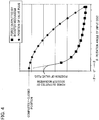
- Fig. 4 is a graph illustrating a relation between the force outputted by the booster mechanism 15 and the position of the valve plug 6.
- the horizontal axis represents rotation angles of the input disc 17, and a rotation angle of the input disc 17 when the links 19 are parallel to the axis CL of the cylinder 16 is set to "0°.”
- the vertical axis represents forces outputted by the booster mechanism 15 and positions of the valve plug 6 and shows that the valve plug 6 comes closer to the valve seat 5 as the line rises from the lower side to the upper side of the graph.
- the rotation of the motor 12 is transmitted from the input disc 17 to the output disc 18 via the links 19.
- the open/close speed of the valve plug 6 is slow, but the force outputted by the booster mechanism 15 (a force to press the valve plug 6 against the valve seat 5) is large.
- the force outputted by the booster mechanism 15 is small, but the open/close speed of the valve plug 6 is fast.
- the booster mechanism 15 further includes a load limiter 23 and a stopper (a mechanical stopper) 24.
- the load limiter 23 is provided between the output disc 18 and the valve plug 6 of the poppet valve 2, and limits the load transmitted from the output disc 18 to the valve seat 5 via the valve plug 6.
- a disc spring 25 is interposed between the output disc 18 of the booster mechanism 15 and the valve plug 6 of the poppet valve 2. This allows the disc spring 25 to exert a function as the load limiter 23 that prevents a predetermined amount or more of a load from being transmitted from the output disc 18 to the valve seat 5 via the valve plug 6 (see Fig. 4 ).
- a characteristic of the load limiter 23 can be changed by changing the number and the combination of the disc springs 25 (parallel, straight, or parallel-straight).
- the stopper 24 is formed on the inner periphery of the cylinder 16 and restricts the movement of the link 19.
- the stopper 24 is provided at an advanced position which the link 19 reaches when moved a bit more beyond a position where the link 19 comes in parallel to the axis CL of the cylinder 16, and the stopper 24 only allows the link 19 to move up to the position of the stopper 24.
- This allows the disc spring 25 and the stopper 24 to exert a function as a latching mechanism that enables the valve plug 6 to stay at the completely-closed position even when the power for the motor 12 turns off.
- valve plug 6 since it is needed to apply a force determined by the disc spring 25 to the valve plug 6 to make the valve plug 6 back to the open direction from the state illustrated in Fig. 3B , the valve plug 6 will not move back to the open direction unless such a force is applied thereto.
- the valve plug 6 coupled with the output disc 18 can reliably stop at a predetermined position (for example, the completely-closed position).
- the stopper 24 since the stopper 24 is disposed at the advanced position beyond the position where the link 19 comes in parallel to the axis CL of the cylinder 16, the stopper 24 can exert a function as a latching mechanism.
- valve actuator of the present disclosure is described with the above-described embodiment as an example, it is not limited thereto. Various other embodiments can be employed without departing from the scope of the present disclosure.
- the connecting portions between the input disc and the links as well as the connecting portions between the output disc and the links are not limited to the ball joints, and universal joints may also be used.
- the number of the links that connect the input disc and the output disc is not limited to three, but the number can be selected arbitrarily.
Landscapes
- Engineering & Computer Science (AREA)
- General Engineering & Computer Science (AREA)
- Mechanical Engineering (AREA)
- Mechanically-Actuated Valves (AREA)
- Transmission Devices (AREA)
Applications Claiming Priority (2)
| Application Number | Priority Date | Filing Date | Title |
|---|---|---|---|
| JP2015223058A JP6609168B2 (ja) | 2015-11-13 | 2015-11-13 | バルブアクチュエータ |
| PCT/JP2016/082810 WO2017082168A1 (fr) | 2015-11-13 | 2016-11-04 | Actionneur de soupape |
Publications (3)
| Publication Number | Publication Date |
|---|---|
| EP3376083A1 true EP3376083A1 (fr) | 2018-09-19 |
| EP3376083A4 EP3376083A4 (fr) | 2019-07-24 |
| EP3376083B1 EP3376083B1 (fr) | 2022-06-01 |
Family
ID=58696000
Family Applications (1)
| Application Number | Title | Priority Date | Filing Date |
|---|---|---|---|
| EP16864130.6A Active EP3376083B1 (fr) | 2015-11-13 | 2016-11-04 | Actionneur de soupape |
Country Status (5)
| Country | Link |
|---|---|
| US (1) | US10527189B2 (fr) |
| EP (1) | EP3376083B1 (fr) |
| JP (1) | JP6609168B2 (fr) |
| RU (1) | RU2685171C1 (fr) |
| WO (1) | WO2017082168A1 (fr) |
Cited By (2)
| Publication number | Priority date | Publication date | Assignee | Title |
|---|---|---|---|---|
| WO2023041993A1 (fr) * | 2021-09-20 | 2023-03-23 | Weatherford Technology Holdings, Llc | Système de commande de forage à pression régulée avec transmission à variation continue |
| US11988064B2 (en) | 2016-12-12 | 2024-05-21 | Weatherford Technology Holdings, Llc | Managed pressure drilling control system with continuously variable transmission |
Families Citing this family (3)
| Publication number | Priority date | Publication date | Assignee | Title |
|---|---|---|---|---|
| CN108561264B (zh) * | 2018-05-22 | 2024-03-19 | 西南交通大学 | 一种用于跨海大桥的波浪能回收装置 |
| US11306806B2 (en) * | 2019-04-11 | 2022-04-19 | Danbury Mission Technologies, Llc | Actuators for converting rotational input to axial output |
| JP7229479B2 (ja) * | 2019-06-24 | 2023-02-28 | Ntn株式会社 | ロケットエンジンのバルブアクチュエータ |
Family Cites Families (29)
| Publication number | Priority date | Publication date | Assignee | Title |
|---|---|---|---|---|
| US3095901A (en) * | 1962-03-16 | 1963-07-02 | Vincent H Larson | Rapid opening valve |
| US3156161A (en) * | 1963-04-10 | 1964-11-10 | Keystone Valve Corp | Pressure fluid actuated fractional rotation operator for valves and the like |
| DE1283168B (de) * | 1964-12-01 | 1968-11-14 | Franz Arnold | Mechanische Spannvorrichtung zur Erzeugung einer hohen Spannkraft |
| GB1145845A (en) * | 1965-10-14 | 1969-03-19 | Lucas Industries Ltd | Device simulating a screw and nut mechanism of varying helix angle |
| JPS4722515Y1 (fr) | 1968-08-16 | 1972-07-21 | ||
| JPS526485A (en) | 1975-07-04 | 1977-01-18 | Murata Mfg Co Ltd | Production process of parallel electric field driving piezo-electric v ibrator |
| US4133215A (en) * | 1976-08-11 | 1979-01-09 | Worcester Controls Ag | Linear-rotary converter |
| US4106170A (en) * | 1976-11-03 | 1978-08-15 | Rockwell International Corporation | Method of assembling a coupling |
| GB2044879B (en) * | 1979-03-29 | 1983-03-16 | Ford J | Drive mechanism for converting rotory to reciprocating motion and vice versa |
| JPS5835425B2 (ja) | 1979-06-18 | 1983-08-02 | 富士通株式会社 | 回線速度制御方式 |
| JPS58196380A (ja) | 1982-05-10 | 1983-11-15 | Shimadzu Corp | バルブ装置 |
| SU1155825A1 (ru) * | 1983-08-12 | 1985-05-15 | Бердский Ордена Трудового Красного Знамени Химический Завод | Клапан |
| US4815699A (en) * | 1987-12-21 | 1989-03-28 | Sundstrand Corporation | Valve with resilient, bellows mounted valve seat |
| JP3526485B2 (ja) | 1995-04-25 | 2004-05-17 | 東京瓦斯株式会社 | 超音波モータを用いた弁アクチュエータ |
| FR2772429B1 (fr) * | 1997-12-16 | 2000-06-02 | Sagem | Vanne de controle pour systeme de recirculation des gaz d'echappement d'un moteur a combustion interne |
| US7086636B2 (en) * | 2002-07-02 | 2006-08-08 | Borgwarner Inc. | Gaseous fluid metering valve |
| RU2234019C2 (ru) * | 2002-07-09 | 2004-08-10 | Путивлев Леонид Иванович | Предохранительно-запорный клапан |
| ITTO20020985A1 (it) * | 2002-11-13 | 2004-05-14 | Skf Ind Spa | Attuatore elettromeccanico lineare a corsa corta. |
| JP4055002B2 (ja) * | 2003-09-02 | 2008-03-05 | Smc株式会社 | 真空調圧用バルブ |
| JP4544927B2 (ja) | 2004-07-15 | 2010-09-15 | 株式会社鷺宮製作所 | 電動式コントロールバルブおよび冷凍サイクル装置 |
| DE202006016354U1 (de) | 2006-10-23 | 2008-02-28 | Asturia Automotive Systems Ag | Einrichtung zum Ausgleich und/oder zur Übertragung von Kräften/Momenten und Drehbewegungen zwischen zwei Bauteilen |
| DE202007008749U1 (de) * | 2007-06-20 | 2008-10-30 | Asturia Automotive Systems Ag | Fußpunktverstellung für Fahrzeugfederungen |
| DE202008007303U1 (de) * | 2008-05-30 | 2009-10-08 | Asturia Automotive Systems Ag | Torsionsschwingungsdämpfer |
| JP2010023185A (ja) | 2008-07-18 | 2010-02-04 | Tokyo Institute Of Technology | 把持装置 |
| DE202008013633U1 (de) * | 2008-10-19 | 2010-03-18 | Asturia Automotive Systems Ag | Differential-Exzentergetriebe |
| JP4469931B1 (ja) * | 2009-05-28 | 2010-06-02 | 克也 水井 | 伸縮装置 |
| JP4581117B1 (ja) | 2010-05-24 | 2010-11-17 | 国立大学法人東京工業大学 | 開閉両方向に力を出せる把持装置 |
| DE102010022736A1 (de) | 2010-06-04 | 2011-12-08 | Mahle International Gmbh | Stellantrieb, Abgasrückführventil, Abgasturbolader |
| JP5600760B2 (ja) | 2013-02-05 | 2014-10-01 | 島津エミット株式会社 | 電動バルブアクチュエータ |
-
2015
- 2015-11-13 JP JP2015223058A patent/JP6609168B2/ja active Active
-
2016
- 2016-11-04 RU RU2018121352A patent/RU2685171C1/ru active
- 2016-11-04 WO PCT/JP2016/082810 patent/WO2017082168A1/fr not_active Ceased
- 2016-11-04 EP EP16864130.6A patent/EP3376083B1/fr active Active
-
2018
- 2018-04-30 US US15/966,573 patent/US10527189B2/en active Active
Cited By (2)
| Publication number | Priority date | Publication date | Assignee | Title |
|---|---|---|---|---|
| US11988064B2 (en) | 2016-12-12 | 2024-05-21 | Weatherford Technology Holdings, Llc | Managed pressure drilling control system with continuously variable transmission |
| WO2023041993A1 (fr) * | 2021-09-20 | 2023-03-23 | Weatherford Technology Holdings, Llc | Système de commande de forage à pression régulée avec transmission à variation continue |
Also Published As
| Publication number | Publication date |
|---|---|
| JP6609168B2 (ja) | 2019-11-20 |
| JP2017089824A (ja) | 2017-05-25 |
| US10527189B2 (en) | 2020-01-07 |
| WO2017082168A1 (fr) | 2017-05-18 |
| EP3376083B1 (fr) | 2022-06-01 |
| US20180245710A1 (en) | 2018-08-30 |
| RU2685171C1 (ru) | 2019-04-16 |
| EP3376083A4 (fr) | 2019-07-24 |
Similar Documents
| Publication | Publication Date | Title |
|---|---|---|
| US10527189B2 (en) | Valve actuator for an electrically actuated poppet valve including a continuously variable transmission and a power free latching mechanism | |
| CN103403382B (zh) | 用于操作车辆离合器的自调整离合器促动器 | |
| CN211869498U (zh) | 车辆转向系统和车辆 | |
| US10125852B2 (en) | Linear driving device, connector and exhaust gas recirculation control valve | |
| NO343325B1 (no) | Koplingsapparat som brukes sammen med elektriske aktuatorer | |
| NO340106B1 (no) | Manuelt overstyringsapparat for lineære aktuatorer | |
| NO20190378A1 (en) | Electric actuator system and method | |
| US11199275B2 (en) | Spool valve | |
| GB2587945A (en) | Spool valve | |
| JP2016133156A (ja) | 電動弁 | |
| KR101028505B1 (ko) | 수동조작으로의 전환이 가능한 자동밸브 | |
| US10125873B2 (en) | Valve assembly with rotatable element | |
| US10399668B2 (en) | Actuator drive disconnection system | |
| CN201802328U (zh) | 液压动力钳液压安全控制系统 | |
| KR101444195B1 (ko) | 나사조임식 버터플라이 밸브 | |
| JP5598021B2 (ja) | 無段変速機及びアクチュエータ | |
| CN114992375B (zh) | 水下阀门液压驱动装置 | |
| CN117212357A (zh) | 一种离合器执行机构及车辆 | |
| JP6763657B2 (ja) | ベルト式無段変速機 | |
| EP3245408A1 (fr) | Actionneur rotatif | |
| RU2725336C1 (ru) | Двухскоростной ручной привод запорной арматуры | |
| EP2832942B1 (fr) | Charnière pour les parties mobiles de carrosseries de véhicule automobile, comme portes, couvercles de coffre, capots et/ou hayons | |
| CN207598637U (zh) | 动态扭矩作用力液压反馈、调节结构 | |
| JP2016028207A (ja) | 無段変速機用アクチュエータ及びこれを備える無段変速機 | |
| KR20160061085A (ko) | 배기가스 재순환 밸브 장치 |
Legal Events
| Date | Code | Title | Description |
|---|---|---|---|
| STAA | Information on the status of an ep patent application or granted ep patent |
Free format text: STATUS: THE INTERNATIONAL PUBLICATION HAS BEEN MADE |
|
| PUAI | Public reference made under article 153(3) epc to a published international application that has entered the european phase |
Free format text: ORIGINAL CODE: 0009012 |
|
| STAA | Information on the status of an ep patent application or granted ep patent |
Free format text: STATUS: REQUEST FOR EXAMINATION WAS MADE |
|
| 17P | Request for examination filed |
Effective date: 20180613 |
|
| AK | Designated contracting states |
Kind code of ref document: A1 Designated state(s): AL AT BE BG CH CY CZ DE DK EE ES FI FR GB GR HR HU IE IS IT LI LT LU LV MC MK MT NL NO PL PT RO RS SE SI SK SM TR |
|
| AX | Request for extension of the european patent |
Extension state: BA ME |
|
| DAV | Request for validation of the european patent (deleted) | ||
| DAX | Request for extension of the european patent (deleted) | ||
| A4 | Supplementary search report drawn up and despatched |
Effective date: 20190621 |
|
| RIC1 | Information provided on ipc code assigned before grant |
Ipc: F16K 1/00 20060101ALI20190614BHEP Ipc: F04B 39/10 20060101ALI20190614BHEP Ipc: F16K 31/04 20060101ALI20190614BHEP Ipc: F16K 31/44 20060101AFI20190614BHEP Ipc: F16K 31/16 20060101ALI20190614BHEP |
|
| RIC1 | Information provided on ipc code assigned before grant |
Ipc: F04B 39/10 20060101ALI20220103BHEP Ipc: F16K 31/04 20060101ALI20220103BHEP Ipc: F16K 1/00 20060101ALI20220103BHEP Ipc: F16K 31/16 20060101ALI20220103BHEP Ipc: F16K 31/44 20060101AFI20220103BHEP |
|
| GRAP | Despatch of communication of intention to grant a patent |
Free format text: ORIGINAL CODE: EPIDOSNIGR1 |
|
| STAA | Information on the status of an ep patent application or granted ep patent |
Free format text: STATUS: GRANT OF PATENT IS INTENDED |
|
| INTG | Intention to grant announced |
Effective date: 20220222 |
|
| GRAA | (expected) grant |
Free format text: ORIGINAL CODE: 0009210 |
|
| GRAS | Grant fee paid |
Free format text: ORIGINAL CODE: EPIDOSNIGR3 |
|
| STAA | Information on the status of an ep patent application or granted ep patent |
Free format text: STATUS: THE PATENT HAS BEEN GRANTED |
|
| AK | Designated contracting states |
Kind code of ref document: B1 Designated state(s): AL AT BE BG CH CY CZ DE DK EE ES FI FR GB GR HR HU IE IS IT LI LT LU LV MC MK MT NL NO PL PT RO RS SE SI SK SM TR |
|
| REG | Reference to a national code |
Ref country code: GB Ref legal event code: FG4D |
|
| REG | Reference to a national code |
Ref country code: AT Ref legal event code: REF Ref document number: 1495581 Country of ref document: AT Kind code of ref document: T Effective date: 20220615 Ref country code: CH Ref legal event code: EP Ref country code: DE Ref legal event code: R096 Ref document number: 602016072594 Country of ref document: DE |
|
| REG | Reference to a national code |
Ref country code: IE Ref legal event code: FG4D |
|
| RIN2 | Information on inventor provided after grant (corrected) |
Inventor name: TAKAKI TAKESHI Inventor name: TANAKA MASAHIRO Inventor name: HIRATA YU Inventor name: HIRAI KENJI Inventor name: MORI HATSUO Inventor name: TAYA KOHEI |
|
| REG | Reference to a national code |
Ref country code: LT Ref legal event code: MG9D |
|
| REG | Reference to a national code |
Ref country code: NL Ref legal event code: MP Effective date: 20220601 |
|
| PG25 | Lapsed in a contracting state [announced via postgrant information from national office to epo] |
Ref country code: SE Free format text: LAPSE BECAUSE OF FAILURE TO SUBMIT A TRANSLATION OF THE DESCRIPTION OR TO PAY THE FEE WITHIN THE PRESCRIBED TIME-LIMIT Effective date: 20220601 Ref country code: NO Free format text: LAPSE BECAUSE OF FAILURE TO SUBMIT A TRANSLATION OF THE DESCRIPTION OR TO PAY THE FEE WITHIN THE PRESCRIBED TIME-LIMIT Effective date: 20220901 Ref country code: LT Free format text: LAPSE BECAUSE OF FAILURE TO SUBMIT A TRANSLATION OF THE DESCRIPTION OR TO PAY THE FEE WITHIN THE PRESCRIBED TIME-LIMIT Effective date: 20220601 Ref country code: HR Free format text: LAPSE BECAUSE OF FAILURE TO SUBMIT A TRANSLATION OF THE DESCRIPTION OR TO PAY THE FEE WITHIN THE PRESCRIBED TIME-LIMIT Effective date: 20220601 Ref country code: GR Free format text: LAPSE BECAUSE OF FAILURE TO SUBMIT A TRANSLATION OF THE DESCRIPTION OR TO PAY THE FEE WITHIN THE PRESCRIBED TIME-LIMIT Effective date: 20220902 Ref country code: FI Free format text: LAPSE BECAUSE OF FAILURE TO SUBMIT A TRANSLATION OF THE DESCRIPTION OR TO PAY THE FEE WITHIN THE PRESCRIBED TIME-LIMIT Effective date: 20220601 Ref country code: ES Free format text: LAPSE BECAUSE OF FAILURE TO SUBMIT A TRANSLATION OF THE DESCRIPTION OR TO PAY THE FEE WITHIN THE PRESCRIBED TIME-LIMIT Effective date: 20220601 Ref country code: BG Free format text: LAPSE BECAUSE OF FAILURE TO SUBMIT A TRANSLATION OF THE DESCRIPTION OR TO PAY THE FEE WITHIN THE PRESCRIBED TIME-LIMIT Effective date: 20220901 |
|
| REG | Reference to a national code |
Ref country code: AT Ref legal event code: MK05 Ref document number: 1495581 Country of ref document: AT Kind code of ref document: T Effective date: 20220601 |
|
| PG25 | Lapsed in a contracting state [announced via postgrant information from national office to epo] |
Ref country code: RS Free format text: LAPSE BECAUSE OF FAILURE TO SUBMIT A TRANSLATION OF THE DESCRIPTION OR TO PAY THE FEE WITHIN THE PRESCRIBED TIME-LIMIT Effective date: 20220601 Ref country code: PL Free format text: LAPSE BECAUSE OF FAILURE TO SUBMIT A TRANSLATION OF THE DESCRIPTION OR TO PAY THE FEE WITHIN THE PRESCRIBED TIME-LIMIT Effective date: 20220601 Ref country code: LV Free format text: LAPSE BECAUSE OF FAILURE TO SUBMIT A TRANSLATION OF THE DESCRIPTION OR TO PAY THE FEE WITHIN THE PRESCRIBED TIME-LIMIT Effective date: 20220601 |
|
| PG25 | Lapsed in a contracting state [announced via postgrant information from national office to epo] |
Ref country code: NL Free format text: LAPSE BECAUSE OF FAILURE TO SUBMIT A TRANSLATION OF THE DESCRIPTION OR TO PAY THE FEE WITHIN THE PRESCRIBED TIME-LIMIT Effective date: 20220601 |
|
| PG25 | Lapsed in a contracting state [announced via postgrant information from national office to epo] |
Ref country code: SM Free format text: LAPSE BECAUSE OF FAILURE TO SUBMIT A TRANSLATION OF THE DESCRIPTION OR TO PAY THE FEE WITHIN THE PRESCRIBED TIME-LIMIT Effective date: 20220601 Ref country code: SK Free format text: LAPSE BECAUSE OF FAILURE TO SUBMIT A TRANSLATION OF THE DESCRIPTION OR TO PAY THE FEE WITHIN THE PRESCRIBED TIME-LIMIT Effective date: 20220601 Ref country code: RO Free format text: LAPSE BECAUSE OF FAILURE TO SUBMIT A TRANSLATION OF THE DESCRIPTION OR TO PAY THE FEE WITHIN THE PRESCRIBED TIME-LIMIT Effective date: 20220601 Ref country code: PT Free format text: LAPSE BECAUSE OF FAILURE TO SUBMIT A TRANSLATION OF THE DESCRIPTION OR TO PAY THE FEE WITHIN THE PRESCRIBED TIME-LIMIT Effective date: 20221003 Ref country code: EE Free format text: LAPSE BECAUSE OF FAILURE TO SUBMIT A TRANSLATION OF THE DESCRIPTION OR TO PAY THE FEE WITHIN THE PRESCRIBED TIME-LIMIT Effective date: 20220601 Ref country code: CZ Free format text: LAPSE BECAUSE OF FAILURE TO SUBMIT A TRANSLATION OF THE DESCRIPTION OR TO PAY THE FEE WITHIN THE PRESCRIBED TIME-LIMIT Effective date: 20220601 Ref country code: AT Free format text: LAPSE BECAUSE OF FAILURE TO SUBMIT A TRANSLATION OF THE DESCRIPTION OR TO PAY THE FEE WITHIN THE PRESCRIBED TIME-LIMIT Effective date: 20220601 |
|
| PG25 | Lapsed in a contracting state [announced via postgrant information from national office to epo] |
Ref country code: IS Free format text: LAPSE BECAUSE OF FAILURE TO SUBMIT A TRANSLATION OF THE DESCRIPTION OR TO PAY THE FEE WITHIN THE PRESCRIBED TIME-LIMIT Effective date: 20221001 |
|
| REG | Reference to a national code |
Ref country code: DE Ref legal event code: R097 Ref document number: 602016072594 Country of ref document: DE |
|
| PG25 | Lapsed in a contracting state [announced via postgrant information from national office to epo] |
Ref country code: AL Free format text: LAPSE BECAUSE OF FAILURE TO SUBMIT A TRANSLATION OF THE DESCRIPTION OR TO PAY THE FEE WITHIN THE PRESCRIBED TIME-LIMIT Effective date: 20220601 |
|
| PLBE | No opposition filed within time limit |
Free format text: ORIGINAL CODE: 0009261 |
|
| STAA | Information on the status of an ep patent application or granted ep patent |
Free format text: STATUS: NO OPPOSITION FILED WITHIN TIME LIMIT |
|
| PG25 | Lapsed in a contracting state [announced via postgrant information from national office to epo] |
Ref country code: DK Free format text: LAPSE BECAUSE OF FAILURE TO SUBMIT A TRANSLATION OF THE DESCRIPTION OR TO PAY THE FEE WITHIN THE PRESCRIBED TIME-LIMIT Effective date: 20220601 |
|
| 26N | No opposition filed |
Effective date: 20230302 |
|
| PG25 | Lapsed in a contracting state [announced via postgrant information from national office to epo] |
Ref country code: SI Free format text: LAPSE BECAUSE OF FAILURE TO SUBMIT A TRANSLATION OF THE DESCRIPTION OR TO PAY THE FEE WITHIN THE PRESCRIBED TIME-LIMIT Effective date: 20220601 |
|
| REG | Reference to a national code |
Ref country code: DE Ref legal event code: R119 Ref document number: 602016072594 Country of ref document: DE |
|
| PG25 | Lapsed in a contracting state [announced via postgrant information from national office to epo] |
Ref country code: MC Free format text: LAPSE BECAUSE OF FAILURE TO SUBMIT A TRANSLATION OF THE DESCRIPTION OR TO PAY THE FEE WITHIN THE PRESCRIBED TIME-LIMIT Effective date: 20220601 |
|
| REG | Reference to a national code |
Ref country code: CH Ref legal event code: PL |
|
| GBPC | Gb: european patent ceased through non-payment of renewal fee |
Effective date: 20221104 |
|
| REG | Reference to a national code |
Ref country code: BE Ref legal event code: MM Effective date: 20221130 |
|
| PG25 | Lapsed in a contracting state [announced via postgrant information from national office to epo] |
Ref country code: LI Free format text: LAPSE BECAUSE OF NON-PAYMENT OF DUE FEES Effective date: 20221130 Ref country code: CH Free format text: LAPSE BECAUSE OF NON-PAYMENT OF DUE FEES Effective date: 20221130 |
|
| PG25 | Lapsed in a contracting state [announced via postgrant information from national office to epo] |
Ref country code: LU Free format text: LAPSE BECAUSE OF NON-PAYMENT OF DUE FEES Effective date: 20221104 |
|
| PG25 | Lapsed in a contracting state [announced via postgrant information from national office to epo] |
Ref country code: IE Free format text: LAPSE BECAUSE OF NON-PAYMENT OF DUE FEES Effective date: 20221104 Ref country code: GB Free format text: LAPSE BECAUSE OF NON-PAYMENT OF DUE FEES Effective date: 20221104 Ref country code: DE Free format text: LAPSE BECAUSE OF NON-PAYMENT OF DUE FEES Effective date: 20230601 |
|
| PG25 | Lapsed in a contracting state [announced via postgrant information from national office to epo] |
Ref country code: BE Free format text: LAPSE BECAUSE OF NON-PAYMENT OF DUE FEES Effective date: 20221130 |
|
| PG25 | Lapsed in a contracting state [announced via postgrant information from national office to epo] |
Ref country code: IT Free format text: LAPSE BECAUSE OF FAILURE TO SUBMIT A TRANSLATION OF THE DESCRIPTION OR TO PAY THE FEE WITHIN THE PRESCRIBED TIME-LIMIT Effective date: 20220601 |
|
| PG25 | Lapsed in a contracting state [announced via postgrant information from national office to epo] |
Ref country code: HU Free format text: LAPSE BECAUSE OF FAILURE TO SUBMIT A TRANSLATION OF THE DESCRIPTION OR TO PAY THE FEE WITHIN THE PRESCRIBED TIME-LIMIT; INVALID AB INITIO Effective date: 20161104 |
|
| PG25 | Lapsed in a contracting state [announced via postgrant information from national office to epo] |
Ref country code: CY Free format text: LAPSE BECAUSE OF FAILURE TO SUBMIT A TRANSLATION OF THE DESCRIPTION OR TO PAY THE FEE WITHIN THE PRESCRIBED TIME-LIMIT Effective date: 20220601 |
|
| PG25 | Lapsed in a contracting state [announced via postgrant information from national office to epo] |
Ref country code: MK Free format text: LAPSE BECAUSE OF FAILURE TO SUBMIT A TRANSLATION OF THE DESCRIPTION OR TO PAY THE FEE WITHIN THE PRESCRIBED TIME-LIMIT Effective date: 20220601 |
|
| PG25 | Lapsed in a contracting state [announced via postgrant information from national office to epo] |
Ref country code: MT Free format text: LAPSE BECAUSE OF FAILURE TO SUBMIT A TRANSLATION OF THE DESCRIPTION OR TO PAY THE FEE WITHIN THE PRESCRIBED TIME-LIMIT Effective date: 20220601 |
|
| PG25 | Lapsed in a contracting state [announced via postgrant information from national office to epo] |
Ref country code: BG Free format text: LAPSE BECAUSE OF FAILURE TO SUBMIT A TRANSLATION OF THE DESCRIPTION OR TO PAY THE FEE WITHIN THE PRESCRIBED TIME-LIMIT Effective date: 20220601 |
|
| PG25 | Lapsed in a contracting state [announced via postgrant information from national office to epo] |
Ref country code: BG Free format text: LAPSE BECAUSE OF FAILURE TO SUBMIT A TRANSLATION OF THE DESCRIPTION OR TO PAY THE FEE WITHIN THE PRESCRIBED TIME-LIMIT Effective date: 20220601 |
|
| PG25 | Lapsed in a contracting state [announced via postgrant information from national office to epo] |
Ref country code: TR Free format text: LAPSE BECAUSE OF FAILURE TO SUBMIT A TRANSLATION OF THE DESCRIPTION OR TO PAY THE FEE WITHIN THE PRESCRIBED TIME-LIMIT Effective date: 20220601 |
|
| PGFP | Annual fee paid to national office [announced via postgrant information from national office to epo] |
Ref country code: FR Payment date: 20251022 Year of fee payment: 10 |