EP3376100A1 - Module d'éclairage led doté du support plat pour led - Google Patents
Module d'éclairage led doté du support plat pour led Download PDFInfo
- Publication number
- EP3376100A1 EP3376100A1 EP18162323.2A EP18162323A EP3376100A1 EP 3376100 A1 EP3376100 A1 EP 3376100A1 EP 18162323 A EP18162323 A EP 18162323A EP 3376100 A1 EP3376100 A1 EP 3376100A1
- Authority
- EP
- European Patent Office
- Prior art keywords
- carrier
- leds
- cover
- luminaire module
- led luminaire
- Prior art date
- Legal status (The legal status is an assumption and is not a legal conclusion. Google has not performed a legal analysis and makes no representation as to the accuracy of the status listed.)
- Granted
Links
Images


Classifications
-
- F—MECHANICAL ENGINEERING; LIGHTING; HEATING; WEAPONS; BLASTING
- F21—LIGHTING
- F21V—FUNCTIONAL FEATURES OR DETAILS OF LIGHTING DEVICES OR SYSTEMS THEREOF; STRUCTURAL COMBINATIONS OF LIGHTING DEVICES WITH OTHER ARTICLES, NOT OTHERWISE PROVIDED FOR
- F21V17/00—Fastening of component parts of lighting devices, e.g. shades, globes, refractors, reflectors, filters, screens, grids or protective cages
- F21V17/10—Fastening of component parts of lighting devices, e.g. shades, globes, refractors, reflectors, filters, screens, grids or protective cages characterised by specific fastening means or way of fastening
- F21V17/104—Fastening of component parts of lighting devices, e.g. shades, globes, refractors, reflectors, filters, screens, grids or protective cages characterised by specific fastening means or way of fastening using feather joints, e.g. tongues and grooves, with or without friction
-
- F—MECHANICAL ENGINEERING; LIGHTING; HEATING; WEAPONS; BLASTING
- F21—LIGHTING
- F21V—FUNCTIONAL FEATURES OR DETAILS OF LIGHTING DEVICES OR SYSTEMS THEREOF; STRUCTURAL COMBINATIONS OF LIGHTING DEVICES WITH OTHER ARTICLES, NOT OTHERWISE PROVIDED FOR
- F21V19/00—Fastening of light sources or lamp holders
- F21V19/001—Fastening of light sources or lamp holders the light sources being semiconductors devices, e.g. LEDs
- F21V19/003—Fastening of light source holders, e.g. of circuit boards or substrates holding light sources
-
- F—MECHANICAL ENGINEERING; LIGHTING; HEATING; WEAPONS; BLASTING
- F21—LIGHTING
- F21V—FUNCTIONAL FEATURES OR DETAILS OF LIGHTING DEVICES OR SYSTEMS THEREOF; STRUCTURAL COMBINATIONS OF LIGHTING DEVICES WITH OTHER ARTICLES, NOT OTHERWISE PROVIDED FOR
- F21V3/00—Globes; Bowls; Cover glasses
- F21V3/02—Globes; Bowls; Cover glasses characterised by the shape
-
- H—ELECTRICITY
- H05—ELECTRIC TECHNIQUES NOT OTHERWISE PROVIDED FOR
- H05K—PRINTED CIRCUITS; CASINGS OR CONSTRUCTIONAL DETAILS OF ELECTRIC APPARATUS; MANUFACTURE OF ASSEMBLAGES OF ELECTRICAL COMPONENTS
- H05K3/00—Apparatus or processes for manufacturing printed circuits
- H05K3/0058—Laminating printed circuit boards onto other substrates, e.g. metallic substrates
- H05K3/0061—Laminating printed circuit boards onto other substrates, e.g. metallic substrates onto a metallic substrate, e.g. a heat sink
-
- F—MECHANICAL ENGINEERING; LIGHTING; HEATING; WEAPONS; BLASTING
- F21—LIGHTING
- F21V—FUNCTIONAL FEATURES OR DETAILS OF LIGHTING DEVICES OR SYSTEMS THEREOF; STRUCTURAL COMBINATIONS OF LIGHTING DEVICES WITH OTHER ARTICLES, NOT OTHERWISE PROVIDED FOR
- F21V23/00—Arrangement of electric circuit elements in or on lighting devices
- F21V23/001—Arrangement of electric circuit elements in or on lighting devices the elements being electrical wires or cables
- F21V23/002—Arrangements of cables or conductors inside a lighting device, e.g. means for guiding along parts of the housing or in a pivoting arm
-
- F—MECHANICAL ENGINEERING; LIGHTING; HEATING; WEAPONS; BLASTING
- F21—LIGHTING
- F21Y—INDEXING SCHEME ASSOCIATED WITH SUBCLASSES F21K, F21L, F21S and F21V, RELATING TO THE FORM OR THE KIND OF THE LIGHT SOURCES OR OF THE COLOUR OF THE LIGHT EMITTED
- F21Y2103/00—Elongate light sources, e.g. fluorescent tubes
- F21Y2103/10—Elongate light sources, e.g. fluorescent tubes comprising a linear array of point-like light-generating elements
-
- F—MECHANICAL ENGINEERING; LIGHTING; HEATING; WEAPONS; BLASTING
- F21—LIGHTING
- F21Y—INDEXING SCHEME ASSOCIATED WITH SUBCLASSES F21K, F21L, F21S and F21V, RELATING TO THE FORM OR THE KIND OF THE LIGHT SOURCES OR OF THE COLOUR OF THE LIGHT EMITTED
- F21Y2103/00—Elongate light sources, e.g. fluorescent tubes
- F21Y2103/30—Elongate light sources, e.g. fluorescent tubes curved
- F21Y2103/33—Elongate light sources, e.g. fluorescent tubes curved annular
-
- F—MECHANICAL ENGINEERING; LIGHTING; HEATING; WEAPONS; BLASTING
- F21—LIGHTING
- F21Y—INDEXING SCHEME ASSOCIATED WITH SUBCLASSES F21K, F21L, F21S and F21V, RELATING TO THE FORM OR THE KIND OF THE LIGHT SOURCES OR OF THE COLOUR OF THE LIGHT EMITTED
- F21Y2105/00—Planar light sources
- F21Y2105/10—Planar light sources comprising a two-dimensional [2D] array of point-like light-generating elements
- F21Y2105/14—Planar light sources comprising a two-dimensional [2D] array of point-like light-generating elements characterised by the overall shape of the two-dimensional [2D] array
- F21Y2105/18—Planar light sources comprising a two-dimensional [2D] array of point-like light-generating elements characterised by the overall shape of the two-dimensional [2D] array annular; polygonal other than square or rectangular, e.g. for spotlights or for generating an axially symmetrical light beam
-
- F—MECHANICAL ENGINEERING; LIGHTING; HEATING; WEAPONS; BLASTING
- F21—LIGHTING
- F21Y—INDEXING SCHEME ASSOCIATED WITH SUBCLASSES F21K, F21L, F21S and F21V, RELATING TO THE FORM OR THE KIND OF THE LIGHT SOURCES OR OF THE COLOUR OF THE LIGHT EMITTED
- F21Y2115/00—Light-generating elements of semiconductor light sources
- F21Y2115/10—Light-emitting diodes [LED]
-
- H—ELECTRICITY
- H05—ELECTRIC TECHNIQUES NOT OTHERWISE PROVIDED FOR
- H05K—PRINTED CIRCUITS; CASINGS OR CONSTRUCTIONAL DETAILS OF ELECTRIC APPARATUS; MANUFACTURE OF ASSEMBLAGES OF ELECTRICAL COMPONENTS
- H05K1/00—Printed circuits
- H05K1/18—Printed circuits structurally associated with non-printed electric components
- H05K1/189—Printed circuits structurally associated with non-printed electric components characterised by the use of flexible or folded printed circuits
-
- H—ELECTRICITY
- H05—ELECTRIC TECHNIQUES NOT OTHERWISE PROVIDED FOR
- H05K—PRINTED CIRCUITS; CASINGS OR CONSTRUCTIONAL DETAILS OF ELECTRIC APPARATUS; MANUFACTURE OF ASSEMBLAGES OF ELECTRICAL COMPONENTS
- H05K2201/00—Indexing scheme relating to printed circuits covered by H05K1/00
- H05K2201/01—Dielectrics
- H05K2201/0104—Properties and characteristics in general
- H05K2201/0108—Transparent
-
- H—ELECTRICITY
- H05—ELECTRIC TECHNIQUES NOT OTHERWISE PROVIDED FOR
- H05K—PRINTED CIRCUITS; CASINGS OR CONSTRUCTIONAL DETAILS OF ELECTRIC APPARATUS; MANUFACTURE OF ASSEMBLAGES OF ELECTRICAL COMPONENTS
- H05K2201/00—Indexing scheme relating to printed circuits covered by H05K1/00
- H05K2201/01—Dielectrics
- H05K2201/0137—Materials
- H05K2201/0145—Polyester, e.g. polyethylene terephthalate [PET], polyethylene naphthalate [PEN]
-
- H—ELECTRICITY
- H05—ELECTRIC TECHNIQUES NOT OTHERWISE PROVIDED FOR
- H05K—PRINTED CIRCUITS; CASINGS OR CONSTRUCTIONAL DETAILS OF ELECTRIC APPARATUS; MANUFACTURE OF ASSEMBLAGES OF ELECTRICAL COMPONENTS
- H05K2201/00—Indexing scheme relating to printed circuits covered by H05K1/00
- H05K2201/03—Conductive materials
- H05K2201/032—Materials
- H05K2201/0323—Carbon
-
- H—ELECTRICITY
- H05—ELECTRIC TECHNIQUES NOT OTHERWISE PROVIDED FOR
- H05K—PRINTED CIRCUITS; CASINGS OR CONSTRUCTIONAL DETAILS OF ELECTRIC APPARATUS; MANUFACTURE OF ASSEMBLAGES OF ELECTRICAL COMPONENTS
- H05K2201/00—Indexing scheme relating to printed circuits covered by H05K1/00
- H05K2201/06—Thermal details
- H05K2201/066—Heatsink mounted on the surface of the printed circuit board [PCB]
-
- H—ELECTRICITY
- H05—ELECTRIC TECHNIQUES NOT OTHERWISE PROVIDED FOR
- H05K—PRINTED CIRCUITS; CASINGS OR CONSTRUCTIONAL DETAILS OF ELECTRIC APPARATUS; MANUFACTURE OF ASSEMBLAGES OF ELECTRICAL COMPONENTS
- H05K2201/00—Indexing scheme relating to printed circuits covered by H05K1/00
- H05K2201/10—Details of components or other objects attached to or integrated in a printed circuit board
- H05K2201/10007—Types of components
- H05K2201/10106—Light emitting diode [LED]
-
- H—ELECTRICITY
- H05—ELECTRIC TECHNIQUES NOT OTHERWISE PROVIDED FOR
- H05K—PRINTED CIRCUITS; CASINGS OR CONSTRUCTIONAL DETAILS OF ELECTRIC APPARATUS; MANUFACTURE OF ASSEMBLAGES OF ELECTRICAL COMPONENTS
- H05K2201/00—Indexing scheme relating to printed circuits covered by H05K1/00
- H05K2201/20—Details of printed circuits not provided for in H05K2201/01 - H05K2201/10
- H05K2201/2054—Light-reflecting surface, e.g. conductors, substrates, coatings, dielectrics
-
- H—ELECTRICITY
- H05—ELECTRIC TECHNIQUES NOT OTHERWISE PROVIDED FOR
- H05K—PRINTED CIRCUITS; CASINGS OR CONSTRUCTIONAL DETAILS OF ELECTRIC APPARATUS; MANUFACTURE OF ASSEMBLAGES OF ELECTRICAL COMPONENTS
- H05K2203/00—Indexing scheme relating to apparatus or processes for manufacturing printed circuits covered by H05K3/00
- H05K2203/07—Treatments involving liquids, e.g. plating, rinsing
- H05K2203/0756—Uses of liquids, e.g. rinsing, coating, dissolving
- H05K2203/0759—Forming a polymer layer by liquid coating, e.g. a non-metallic protective coating or an organic bonding layer
Definitions
- the invention relates to an LED luminaire module, which e.g. is designed for use in indoor or outdoor lighting for lighting purposes or is designed as a complete luminaire, and in particular an LED luminaire module, which has a flat carrier, which is equipped with LEDs (Light Emitting Diodes, by which any type of semiconductor light sources is to understand) ,
- LEDs Light Emitting Diodes, by which any type of semiconductor light sources is to understand
- the LED luminaire module comprises a support for the LEDs in the form of a printed circuit board, also known as a printed circuit board, which not only carries the LEDs but is also set up for the electrical contacting of the LEDs.
- a lighting fixture is in the DE 20 2009 011 688 U1 described.
- the LEDs are arranged on a printed circuit board, the printed circuit board possibly also being designed as a metal core printed circuit board in order to better dissipate the heat generated by the LEDs.
- the circuit board itself serves as a back wall for the lighting fixture.
- the LED carrier of this lighting device comprises a ceramic substrate or a metal core board.
- the LED carrier is in this case thermally connected to a heat sink.
- a disadvantage of the mentioned modules is that a printed circuit board populated with LEDs is relatively expensive both because of the materials and also because of the production. It adds to aggravating that due to a necessary thermal cooling of the LEDs usually metal core boards must be used, which are even more expensive than ordinary plastic circuit boards.
- Object of the present invention is to provide a cost-effective variant of an LED lighting module, which is simple in construction and the special thermal requirements that require LEDs as a light source, is fair.
- the object is achieved by an LED luminaire module according to claim 1 and a manufacturing method according to claim 19.
- a special feature of the LED lighting module according to the present invention is the design of the flat support of the LEDs of a painted metal sheet.
- An inexpensive producible metal sheet can replace the circuit board as a classic carrier of the LEDs.
- the metal sheet is electrically insulated from the LEDs mounted thereon by painting.
- the paint can be inexpensively made on the sheet, but meets the requirements for the necessary electrical insulation for a lighting module.
- the coating can also be used for other functions in the luminaire module, in particular as a reflector surface.
- the sheet can be brought into a desired shape, which is not readily possible with a conventional printed circuit board with or without a metal core.
- the carrier is tape-coated on the at least one surface side.
- a strip coating also known as roll coating, can be easily produced in large-scale industrial production and is suitable for producing a thin, homogeneous and even high-gloss lacquer layer on the metal sheet.
- the tape coating has the advantage that the connection between the lacquered insulating layer and the metal sheet is formed in such a way that even the lacquered metal sheet can be subsequently reshaped without damaging the lacquer layer.
- the layer thickness of the coating is between 5 .mu.m and 80 .mu.m, in particular between 10 .mu.m and 35 .mu.m.
- the thin lacquer layer is sufficient to provide the necessary electrical insulation.
- a thin paint does not tend to crack if the material is subject to mechanical or thermal influences.
- materials for painting carbon-based polymers, polyurethane, polyester and epoxy-phenol based materials are generally preferred. Possibly.
- required binders can be based on polyester resin, melamine, acrylate or alkyd resin.
- the coating is reflective.
- the metal sheet can also be used as a reflector for the lamp.
- the LEDs are electrically contacted by means of metallic coating applied to the paint.
- the conductor tracks are also electrically insulated from the metal sheet by the coating.
- the conductor tracks can have a layer thickness between 10 ⁇ m and 100 ⁇ m.
- Such interconnects are also suitable for the metal sheet after the assembly with LEDs and the conductor still reshape without damage to the tracks.
- copper, gold, aluminum, tinplate, metallic alloys and electrically conductive pastes are preferred as materials for the conductor tracks. Should a continuous reflective surface of the carrier be required, a reflective solder mask can also be applied to the conductor track.
- the LED lamp module further comprises a cover of an at least partially transparent material (in particular of a transparent plastic such as PMMA or PU) and the cover is arranged opposite the at least one surface side, so that the light of the LEDs predominantly or completely passes through the cover.
- a cover of an at least partially transparent material in particular of a transparent plastic such as PMMA or PU
- the cover is arranged opposite the at least one surface side, so that the light of the LEDs predominantly or completely passes through the cover.
- the cover is integrated together with the carrier in an LED lamp module, because over the lifetime of the LED module usually the LEDs do not need to be replaced. However, it is possible that the parts are also separable from each other.
- the transparent cover can simultaneously perform two functions. On the one hand, the cover can have light-directing properties in order to produce a desired light distribution of the LED luminaire module. Furthermore, the cover can also provide protection for the LEDs and other electrical components. This protection can be a touch protection.
- the live parts are not accessible.
- the touch with a tool such as a screwdriver or a wire should be prevented.
- the cover can also protect against moisture or dust. This is particularly advantageous for luminaire modules, which are used in outdoor or damp-proof lighting, advantage. It can be produced inexpensively the required protection class.
- the flat carrier is connected by a positive connection and / or a frictional connection with the cover, in particular inserted in pre and / or recesses of the cover or clamped.
- the cover is glued to the flat carrier or is connected by separate mechanical fastening means.
- the planar carrier is connected to the cover such that one or more edges of the flat carrier are covered.
- edges can be inserted or clamped in depressions of the cover, so that the cover is not only mechanically held, but also ensures contact protection on the edges.
- the edges are often sharp-edged in the carriers used when the carriers are made by punching. In this area, therefore, the protective insulation is disturbed.
- a safety cover In the event that the carrier is live, therefore, a safety cover must be ensured for safety reasons. This can easily be achieved in the preferred embodiment by holding the edges in the carrier so that they can not be touched from the outside.
- the edges can be inserted in recesses, in particular in elongated grooves, so that the gap between the insulation of the carrier and the adjacent Side wall of the carrier is so small that a contact with the edge of the carrier is effectively prevented even with a wire or a screwdriver.
- the cover may in particular be formed by an injection-molded plastic cover, for example in the form of a trough.
- the cover may also be formed from a glass.
- the cover can be connected, for example, with clips or by gluing to the carrier, in particular to the edges of the carrier.
- the cover may also be secured to the support by fasteners which are secured to the support in the same manner as the LEDs, eg, metal domes on which the cover is mounted.
- the cover may also include integral lens or prism elements which are aligned with the LEDs by attachment to the carrier.
- the carrier has a concave or convex curvature.
- the curvature can be achieved by clamping the carrier, for example in a cover.
- the width of the carrier determines the strength of the curvature.
- This embodiment is advantageous in conjunction with a reflective finish because the desired concave or convex curvature produces a corresponding reflector.
- the curvature can extend over a large area over the entire carrier.
- the entire support, or at least a portion of the support comprising a multiple of the spatial extent of the LEDs (eg, 10 times) may be curved.
- the carrier serving as a reflector can deflect the light of a plurality of LEDs mounted thereon together. the opposite are arrangements in which only locally curved reflector surfaces are provided for each LED, to produce more complex and also require a greater effort to contact the LEDs electrically.
- plug-in connections are provided on the carrier which extend through the carrier from the at least one surface side with the LEDs to the opposite side and are adapted to electrically connect the carrier and / or mechanically to a luminaire component.
- plug contacts may be passed through openings or through edge cutouts of the sheet metal carrier, which are connected on the side carrying the LEDs with electrical conductors and provide an electrical connection on the opposite side of the carrier.
- the carrier can be plugged, for example, into corresponding socket in a luminaire housing or module housing.
- These plug-in elements can also take over the function of mechanically holding the carrier or the entire luminaire module. It may also serve some connectors or all connectors only for mechanically holding the carrier or the LED lamp module.
- further electrical components are provided on the at least one surface side next to the LEDs.
- the electrical components are arranged at a distance from the LEDs, so that the emission angle of the LEDs is not limited by the other electrical components or less than 10 °.
- the electrical component is at least at such a distance to the LED arranged that an outgoing light beam from the LED, which has an angle to the support of more than 10 °, does not impinge on the electronic component.
- the minimum distance between the LEDs and the other electrical components therefore also depends on the height of the electrical component and on the bending radius of the flat carrier.
- the arrangement of the electronic components on the carrier has the advantage that the electronic components can be connected directly to the LEDs via the printed conductors on the carrier. By attaching the electrical components on the occupied with the LEDs page no expensive electrical feedthrough to the back of the carrier formed of sheet metal needs to be established. It can be provided with the LEDs only on one side of the carrier all electrical connections, possibly apart from electrical feedthroughs of the aforementioned connector.
- the flat carrier is formed at one or more edges.
- the edge can also be brought into a shape which is suitable for cooperating with projections and / or recesses of an adjacent component of the module, eg the cover, in order to mechanically hold the carrier against the component.
- the edges may be bent on the side facing away from the LEDs and pushed or clamped in a corresponding recess of a housing or a cover.
- the edge regions of the carrier are bent in the direction of the surface normal of the sides of the carriers occupied by the LEDs, for example to form a housing and / or a reflector.
- the carrier is strip-shaped or annular. As a result, can be produced in a cost effective manner elongated or circular LED lighting modules.
- the carrier has a thickness of between 0.3 mm and 1.2 mm, in particular between 0.4 mm and 0.9 mm.
- the wall thickness is completely sufficient for metal sheets to provide the necessary stability. It should be noted that wall thicknesses can be made substantially thinner than conventional LED circuit boards.
- the planar carrier may be bonded to a housing component on the side opposite the LEDs.
- a housing component on the side opposite the LEDs.
- a film with insulating properties e.g. Kapton, especially suitable.
- all electrical components on the side facing away from the adhesive side of the carrier can be attached.
- the carrier can even be glued on curved surfaces of a housing portal.
- a further advantage is when the bond between the carrier and the adjacent lighting portal is full-surface, because then a good thermal contact between the metallic support and the adjacent component, which may optionally act as a heat sink, is given.
- the carrier may be provided with a housing component be connected.
- the cover can also be connected to a housing component.
- the cover may have hook-shaped projections which engage in the corresponding undercuts of a housing profile.
- the luminaire module comprises a carrier 2, which is formed flat and is made of a metal sheet.
- the support is preferably a tape-coated steel sheet (however, other metals such as aluminum are possible), since this material has very good reflective properties and can be produced extremely inexpensively.
- the steel sheet has a thickness of about 0.7 mm while the coating has a layer thickness of less than 50 microns.
- the paint is made of an electrically insulating material (eg carbon-based polymers).
- the painted carrier 2 is directly connected to a series of LEDs 4 (which is shown in FIG FIG. 1 only one can be seen in the side view).
- conductor tracks are applied directly to the paint of the carrier, for example with a copper application by a plasma process or by applying an electrically conductive phase with a stencil printing and subsequent thermal curing.
- the tracks serve to electrically contact the LEDs 4.
- the carrier 2 is in the in FIG. 1 illustrated embodiment adhesively bonded by means of a double-sided adhesive film 6 on a portion of a housing bottom 8.
- the housing bottom 8 is the FIG. 1 only in one section shown.
- the film 6 may for example have a thickness of less than 200 microns.
- the material DuPont Kapton NH of 25 microns thickness can be used. Kapton has the advantage that it has very good electrical insulating properties.
- the housing 8 may be formed of plastic or an extruded metal profile, for example.
- FIG. 1 is schematically indicated by the rectangle 10 that the carrier 2, the carrier 2 located thereon and the LEDs 4 are surrounded with a contact protection.
- This contact protection can be formed for example by a cover in conjunction with housing components.
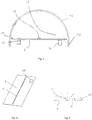
- FIG. 2 shows an alternative embodiment of an LED light module.
- the carrier 2 is not glued to a housing wall 8, as in the embodiment according to FIG. 1 , but arranged cantilevered in a cover 12.
- the cover 12 is formed of a transparent plastic and has on the inside two opposite grooves 14, in which the carrier 2 is inserted lengthwise.
- connectors 16 are also provided in this embodiment, which are inserted into openings of the carrier 2.
- the connectors 16 are electrically connected to the tracks that contact the LEDs 4.
- the connectors On the opposite side of the LEDs, the connectors have a socket which is adapted to be plugged into an opposite plug (not shown in the figures) located, for example, in a housing bottom, thereby mechanically locking the LED lamp module hold as well as connect electrically.
- the cover 12 in this embodiment at the outer ends of a hook-shaped contour 14 which is adapted to be inserted also in recesses of an opposing housing portal, in order to additionally secure the LED lamp module mechanically.
- FIG. 3 shows a variant of the embodiment according to FIG. 2 ,
- an electronic component 18 is additionally arranged on the carrier 2 on the upper side carrying the LEDs 4.
- the electronic component 18 is an LED driver, which is connected to the LEDs 4 on the carrier 2 by means of the previously described conductor tracks. Further, the electronic component 18 is connected to one of the connectors 16 to supply it electrically.
- the opposite connector 16 is formed only as a mechanical support.
- the LEDs 4 on the carrier 2 are arranged in a row one behind the other.
- the electronic component 18 is arranged at a considerable distance, wherein the distance is selected as a function of the emission angle of the LEDs 4.
- the electronic component 18 protrudes into the emission region of the LEDs 4 due to its height.
- the emission range of the LED is limited only insignificantly.
- the arrangement of the electronic component 18 has the same Side of the carrier as the LEDs 4 has the advantage that, apart from the one connector 16 no passage contact must be made more through the metal sheet 2.
- FIG. 6 shows an alternative embodiment in which the carrier 2 at the edges transformations 20 has.
- the deformations of the edges increase the bending strength of the carrier 2 in the longitudinal direction.
- they are set up to cooperate in a form-fitting manner with bulges 22 in the cover 12 in order to hold the carrier 2 in the luminaire module.
- the cover 12 is held by means of the previously described hook-shaped contour 17 on a housing trough 8. It is advantageous that the forces for holding the carrier 2 in the cover 12 are exactly opposite to the forces between the hook-shaped contour 17 and the housing trough 8. By this combination, the components can be joined together without further fasteners are necessary.
- the housing trough 8 can be designed as a closed trough. However, it is possible to provide only one rail 8, in which the cover 12 is inserted.
- housing pan 8 is formed as a continuous profile to provide the live cables 26 as through-wiring along the profile.
- FIGS. 7 and 8 show alternative embodiments in which the carrier 2 is inserted under tension in the cover 12, so that the carrier 2 in the direction of the light exit surface of the LED light module a concave ( FIG. 7 ) or convex ( FIG. 8 ) Has curvature.
- the carrier 2 is designed in these embodiments with a smaller wall thickness, for example 0.5 mm.
- a bias on the carrier 2 is achieved, which achieves a desired defined arc shape of the carrier 2 over the entire carrier.
- the light-directing properties of the acting as a reflector carrier 2 can be set.
- slits 30 are provided in the carrier 2 in this embodiment, which decouple a portion of the light in the direction opposite to the main emission of the LEDs opposite sides. This proportion of light can be used, for example, to form an indirect light component of the LED luminaire module.
- the carrier 2 is inserted into opposite grooves 14 of the cover 12.
- the embodiment according to FIG. 8 In contrast, no additional facilities on the cover 12 are necessary.
- the sharp edges of the carrier 2 formed as a sheet metal spanned in the cover 12, so that the carrier can be held in the cover 12.
- FIGS. 9 and 10 a further embodiment of the LED light module is shown.
- the carrier 2 and the cover 12 is annular. Since a deep drawing of the tape-coated sheet of the carrier 2 is possible, annular modules can be produced inexpensively.
- the carrier 2 can as in the previous described embodiments are secured in the cover 12 by a force and / or positive connection. Also in this embodiment, integrated electrical components and electrical connectors are possible.
- FIGS. 11 to 14 a further embodiment of an LED light module and its manufacture will be described.
- the manufacturing process begins with the provision of a flat carrier.
- the flat carrier consists of a painted sheet steel. Alternatively, aluminum sheet is also considered.
- the paint can be, for example, a tape coating. It may also be provided a composite sheet with a plastic coating. For a simple insulation, a coating with a thickness between 5 ⁇ m and 50 ⁇ m is sufficient. For an increased insulation, an insulation with a thickness of 5 microns to 100 microns may be provided.
- the carrier 2 is formed by a stamping process. Edge regions of the carrier 2 are cut such that they are suitable for a later forming process for forming sidewall regions of the LED module. Furthermore, a bushing 32 for an electrical terminal and openings 34 for a holder as a ceiling installation element is already integrated in the carrier 2.
- the electrical terminal may be configured to contact printed conductors applied to the substrate.
- the electrical clamp and fixture elements may cover the edges of the apertures 32, 34 and, in particular, be latched therewith.
- the LEDs 4 are mechanically attached and electrically contacted before the forming on the carrier 2. It is advantageous that the carrier is still flat. Furthermore, an electrical component 18 in the form of an integrated driver for the LEDs is also applied to the carrier 2. All electrical components have a sufficient minimum distance to the bends, which are bent in the subsequent step.
- the edge regions of the carrier 2, in the illustrated embodiment along all four edges, are deformed in the direction of the surface normal on the surface of the LEDs. The result is in FIG. 13 shown.
- the edge regions of the carrier 2 in this embodiment form the side walls of the LED module.
- an at least partially transparent cover 12 is placed on the module, as in FIG FIG. 14 shown.
- the transparent cover 12 has, on the side facing the edge regions of the carrier 2, integrated grooves 14, which are plugged onto the outer edges of the carrier.
- This type of connection has the advantage that all outer edges of the carrier 2 are covered by the cover. This is not only easy to manufacture but also has the advantage that the edges of the carrier 2 that are sharp-edged by the punching process are protected against contact. A risk of injury is therefore counteracted. Furthermore, an electrical contact protection is ensured in the event that the carrier 2 itself is live.
- the grooves 14 of the cover 12 close tightly against the carrier 2, so that even by a screwdriver or a wire, a contact of the exposed edges of the carrier 2 is prevented.
- the cover 12 may also have projections, in particular with grooves, which also the lateral The edges of the erected side walls of the module overlap and cover it.
- the cover 12 may be fastened to the carrier 2 via latching elements, in particular with a latching connection between the lateral edges of the side walls or between the corner regions of the surface on which the LEDs are mounted, and the protrusions of the cover.
- the illustrated LED luminaire module is suitable, for example, as a recessed luminaire for a ceiling or as an insert module for a surface-mounted luminaire.
- the structure of the LED light module is formed so that it is non-destructive non-solvable. This is not necessary because the LEDs and LED driver are maintenance free and have a relatively long lifetime. The module therefore only has to be exchanged as a whole if there is a defect.
- This LED module is designed for a luminaire, in particular for a luminaire with a higher degree of protection (eg IP44 or higher).
- the manufacturing process begins with the provision of a lacquered elongate carrier 2, which is initially populated with LEDs 4.
- the LEDs 4 can in particular in a row, as in FIG. 15 can be shown, arranged and electrically connected to each other in this series.
- the application of the LEDs may either be a repetitive conductor structure or be endless, with endless preference being given to the simple manufacturing process.
- In the endless assembly can be provided that separation points between the LEDs are not equipped to allow a cutting of the carrier.
- too defined positions in the row of LEDs are replaced by a line bridge (0-ohm resistor). At this point, the carrier 2 can be cut to length without an LED being destroyed.
- the carrier 2 As in FIG. 16 shown, reshaped.
- the two longitudinal regions of the carrier 2 are repeatedly formed.
- the bends may be formed by a roll forming process.
- This method is particularly in elongate carriers 2 as in the embodiment according to FIGS. 15 to 17 shown, an advantage.
- other methods in particular folding, thermoforming or deep drawing into consideration.
- the already mounted electrical components, in particular the LEDs 4 are covered to prevent damage to the LEDs by the hydraulic fluid used (eg a water-oil mixture).
- the in FIG. 16 illustrated carrier can then be integrated into a lamp housing 40 and provided with a cover 12.
- the cover can be attached by dome-shaped fasteners to projections of the housing 40.
- the fasteners may be attached to the carrier 2 in the same manner as the LED.
- the deformed edge region of the carrier 2 has a run-on slope 42 and a recessed region 44. Due to the elasticity of the metal sheet of the carrier 2, these areas are elastic, so that a cover, for example in the form of an optical well as in FIG. 17 represented, with retaining lugs 46 can be attached to the edge regions of the carrier 2.
- a cover for example in the form of an optical well as in FIG. 17 represented, with retaining lugs 46 can be attached to the edge regions of the carrier 2.
- between the housing 40 and the Cover 12 still provided a seal to form the light higher degree of protection.
- FIGS. 18 and 19 show a further alternative embodiment.
- the carrier 2 is bent several times in the edge region in the direction of the surface normal to the LEDs.
- This curvature structure is particularly suitable for the formation of defined optical properties of the carrier when the carrier is used as a reflector.
- FIG. 19 a cross section through the carrier 2 is shown.
- the facing to the LEDs 4 inner surfaces are preferably formed light-reflecting.
- a cover in the form of a primary optic is mounted directly above the LEDs 4.
- the integrated structure shown is suitable, for example, for use in a rail system to form a luminaire.
- the embodiments are not limited to the concrete shapes of the carriers formed from sheet metal and the various covers.
- the cover is formed so that it completely surrounds the carrier 2 on the side occupied by the LEDs without gaps, so that a contact protection of the electronic components is ensured on the carrier.
- diodes, resistors, 0-ohm resistors and / or capacitors can be arranged on the carrier and contacted electrically.
- the LED light module can also be designed as a light.
- the lamp can be an outdoor lamp, such. As a street lamp or tunnel light, and an interior light, such as a recessed light, surface-mounted luminaire, pendant or floor lamp, be.
Landscapes
- Engineering & Computer Science (AREA)
- General Engineering & Computer Science (AREA)
- Manufacturing & Machinery (AREA)
- Microelectronics & Electronic Packaging (AREA)
- Non-Portable Lighting Devices Or Systems Thereof (AREA)
- Fastening Of Light Sources Or Lamp Holders (AREA)
- Arrangement Of Elements, Cooling, Sealing, Or The Like Of Lighting Devices (AREA)
Applications Claiming Priority (1)
| Application Number | Priority Date | Filing Date | Title |
|---|---|---|---|
| DE102017105722.6A DE102017105722A1 (de) | 2017-03-16 | 2017-03-16 | LED-Leuchtenmodul mit flächigem Träger für LEDs |
Publications (3)
| Publication Number | Publication Date |
|---|---|
| EP3376100A1 true EP3376100A1 (fr) | 2018-09-19 |
| EP3376100B1 EP3376100B1 (fr) | 2025-10-29 |
| EP3376100C0 EP3376100C0 (fr) | 2025-10-29 |
Family
ID=61691696
Family Applications (1)
| Application Number | Title | Priority Date | Filing Date |
|---|---|---|---|
| EP18162323.2A Active EP3376100B1 (fr) | 2017-03-16 | 2018-03-16 | Module d'éclairage led doté du support plat pour led |
Country Status (3)
| Country | Link |
|---|---|
| EP (1) | EP3376100B1 (fr) |
| DE (1) | DE102017105722A1 (fr) |
| PL (1) | PL3376100T3 (fr) |
Families Citing this family (1)
| Publication number | Priority date | Publication date | Assignee | Title |
|---|---|---|---|---|
| DE102019114547A1 (de) * | 2019-05-29 | 2020-12-03 | Siteco Gmbh | Befestigung eines Geräteträgers in einer optischen Abdeckung ohne Zusatzbauteile |
Citations (6)
| Publication number | Priority date | Publication date | Assignee | Title |
|---|---|---|---|---|
| WO2010016950A1 (fr) * | 2008-08-07 | 2010-02-11 | Relume Technologies, Inc. | Écrans anti-éblouissement individuels |
| DE102009054840A1 (de) * | 2009-12-17 | 2011-06-22 | Poly-Tech Service GmbH, 67681 | Leuchtmittel mit einer Mehrzahl von Leuchtdioden |
| US20120201023A1 (en) * | 2009-10-06 | 2012-08-09 | Ccs Inc. | Light irradiating device |
| US20140321110A1 (en) * | 2013-04-29 | 2014-10-30 | Lextar Electronics Corporation | Light tube device |
| US20150233533A1 (en) * | 2012-09-21 | 2015-08-20 | Koninklijke Philips N.V. | Led based line illumination luminaire and system |
| EP3222902A2 (fr) * | 2016-03-24 | 2017-09-27 | Zumtobel Lighting GmbH | Platine à del pour éclairage, procédé de fabrication pour une platine à del et éclairage |
Family Cites Families (7)
| Publication number | Priority date | Publication date | Assignee | Title |
|---|---|---|---|---|
| US8188503B2 (en) * | 2004-05-10 | 2012-05-29 | Permlight Products, Inc. | Cuttable illuminated panel |
| EP1767849A1 (fr) * | 2005-09-23 | 2007-03-28 | Alcan Technology & Management Ltd. | Dispositif d'éclairage |
| DE102008039364A1 (de) | 2008-08-22 | 2010-03-04 | Osram Gesellschaft mit beschränkter Haftung | Halbleiter-Leuchtvorrichtung |
| AT11504U1 (de) | 2008-09-01 | 2010-11-15 | Mse Elektronik Gmbh | Beleuchtungskörper mit homogener leuchtfläche bei geringer bauhöhe und hoher lichtausbeute |
| US8313213B2 (en) * | 2009-08-12 | 2012-11-20 | Cpumate Inc. | Assembly structure for LED lamp |
| DE102012108719A1 (de) * | 2012-09-17 | 2014-03-20 | Alanod Gmbh & Co. Kg | Reflektor, Beleuchtungskörper mit einem derartigen Reflektor und Verwendung eines Basismaterials zu dessen Herstellung |
| TW201506301A (zh) * | 2013-08-15 | 2015-02-16 | Luxul Technology Inc | Led燈管 |
-
2017
- 2017-03-16 DE DE102017105722.6A patent/DE102017105722A1/de not_active Withdrawn
-
2018
- 2018-03-16 PL PL18162323.2T patent/PL3376100T3/pl unknown
- 2018-03-16 EP EP18162323.2A patent/EP3376100B1/fr active Active
Patent Citations (6)
| Publication number | Priority date | Publication date | Assignee | Title |
|---|---|---|---|---|
| WO2010016950A1 (fr) * | 2008-08-07 | 2010-02-11 | Relume Technologies, Inc. | Écrans anti-éblouissement individuels |
| US20120201023A1 (en) * | 2009-10-06 | 2012-08-09 | Ccs Inc. | Light irradiating device |
| DE102009054840A1 (de) * | 2009-12-17 | 2011-06-22 | Poly-Tech Service GmbH, 67681 | Leuchtmittel mit einer Mehrzahl von Leuchtdioden |
| US20150233533A1 (en) * | 2012-09-21 | 2015-08-20 | Koninklijke Philips N.V. | Led based line illumination luminaire and system |
| US20140321110A1 (en) * | 2013-04-29 | 2014-10-30 | Lextar Electronics Corporation | Light tube device |
| EP3222902A2 (fr) * | 2016-03-24 | 2017-09-27 | Zumtobel Lighting GmbH | Platine à del pour éclairage, procédé de fabrication pour une platine à del et éclairage |
Also Published As
| Publication number | Publication date |
|---|---|
| PL3376100T3 (pl) | 2026-03-23 |
| EP3376100B1 (fr) | 2025-10-29 |
| EP3376100C0 (fr) | 2025-10-29 |
| DE102017105722A1 (de) | 2018-09-20 |
Similar Documents
| Publication | Publication Date | Title |
|---|---|---|
| EP1831055B1 (fr) | Module de commande | |
| DE102010062331B4 (de) | Herstellungsverfahren für eine LED-Lampe und eine entsprechende LED-Lampe | |
| DE19909399C1 (de) | Flexibles LED-Mehrfachmodul, insb. für ein Leuchtengehäuse eines Kraftfahrzeuges | |
| DE102007041817B4 (de) | Leuchtmodul | |
| EP2863114B1 (fr) | Lampe de surface à DEL | |
| EP2521876A1 (fr) | Dispositif d'éclairage à del et procédé de production d'un dispositif d'éclairage à del | |
| DE102010007522A1 (de) | Beleuchtungseinheit und ein mit der Beleuchtungseinheit ausgerüsteter Leitungssatz | |
| DE102010018018A1 (de) | Niedrigprofilextrusionsteil | |
| DE102006048230A1 (de) | Leuchtdiodensystem, Verfahren zur Herstellung eines solchen und Hinterleuchtungseinrichtung | |
| DE102007055133A1 (de) | Beleuchtungsvorrichtung mit einem Kühlkörper | |
| DE102015207893B3 (de) | Elektronische Baugruppe, insbesondere für ein Getriebesteuermodul | |
| DE102017131063A1 (de) | LED-Modul mit einem stabilisierten Leadframe | |
| EP0373434B1 (fr) | Module de circuit de puissance pour véhicule | |
| DE202018105898U1 (de) | Beleuchtungsvorrichtung mit Leadframe | |
| DE102005044482B4 (de) | Flexible Flachbandleitung mit Elektronikbaugruppe | |
| EP3376100B1 (fr) | Module d'éclairage led doté du support plat pour led | |
| DE202009009802U1 (de) | Leuchten-Moduleinheit | |
| DE102006021973A1 (de) | Leuchte mit wenigstens einer Leuchtmitteleinheit für Fahrzeuge, vorzugsweise für Kraftfahrzeuge | |
| DE102015222187A1 (de) | Wannenleuchte | |
| CH715292A1 (de) | Optikrohling, Optik und Linearleuchte. | |
| EP2738454B1 (fr) | Lampe dotée d'un boîtier de lampe et d'un circuit électronique | |
| EP3763992A1 (fr) | Système d'éclairage ainsi que support d'appareil pour un tel système d'éclairage | |
| WO2017129621A1 (fr) | Lampe à del comprenant un élément directeur de lumière | |
| EP3336419B1 (fr) | Lampe avec élément de positionnement pouvant supporter la platine et les composants optiques | |
| EP3088796B1 (fr) | Rail profile destine au positionnement de modules a del dans des condensateurs lumineux |
Legal Events
| Date | Code | Title | Description |
|---|---|---|---|
| PUAI | Public reference made under article 153(3) epc to a published international application that has entered the european phase |
Free format text: ORIGINAL CODE: 0009012 |
|
| STAA | Information on the status of an ep patent application or granted ep patent |
Free format text: STATUS: THE APPLICATION HAS BEEN PUBLISHED |
|
| AK | Designated contracting states |
Kind code of ref document: A1 Designated state(s): AL AT BE BG CH CY CZ DE DK EE ES FI FR GB GR HR HU IE IS IT LI LT LU LV MC MK MT NL NO PL PT RO RS SE SI SK SM TR |
|
| AX | Request for extension of the european patent |
Extension state: BA ME |
|
| STAA | Information on the status of an ep patent application or granted ep patent |
Free format text: STATUS: REQUEST FOR EXAMINATION WAS MADE |
|
| STAA | Information on the status of an ep patent application or granted ep patent |
Free format text: STATUS: EXAMINATION IS IN PROGRESS |
|
| 17P | Request for examination filed |
Effective date: 20190319 |
|
| RBV | Designated contracting states (corrected) |
Designated state(s): AL AT BE BG CH CY CZ DE DK EE ES FI FR GB GR HR HU IE IS IT LI LT LU LV MC MK MT NL NO PL PT RO RS SE SI SK SM TR |
|
| 17Q | First examination report despatched |
Effective date: 20190409 |
|
| RAP1 | Party data changed (applicant data changed or rights of an application transferred) |
Owner name: SITECO GMBH |
|
| RIC1 | Information provided on ipc code assigned before grant |
Ipc: F21V 17/10 20060101AFI20201102BHEP Ipc: F21Y 115/10 20160101ALN20201102BHEP Ipc: F21Y 103/10 20160101ALN20201102BHEP |
|
| RIC1 | Information provided on ipc code assigned before grant |
Ipc: F21Y 103/10 20160101ALN20241015BHEP Ipc: F21Y 115/10 20160101ALN20241015BHEP Ipc: F21V 17/10 20060101AFI20241015BHEP |
|
| GRAP | Despatch of communication of intention to grant a patent |
Free format text: ORIGINAL CODE: EPIDOSNIGR1 |
|
| RIC1 | Information provided on ipc code assigned before grant |
Ipc: F21Y 103/10 20160101ALN20241113BHEP Ipc: F21Y 115/10 20160101ALN20241113BHEP Ipc: F21V 17/10 20060101AFI20241113BHEP |
|
| STAA | Information on the status of an ep patent application or granted ep patent |
Free format text: STATUS: GRANT OF PATENT IS INTENDED |
|
| RIC1 | Information provided on ipc code assigned before grant |
Ipc: F21Y 103/10 20160101ALN20241210BHEP Ipc: F21Y 115/10 20160101ALN20241210BHEP Ipc: F21V 17/10 20060101AFI20241210BHEP |
|
| INTG | Intention to grant announced |
Effective date: 20241219 |
|
| GRAJ | Information related to disapproval of communication of intention to grant by the applicant or resumption of examination proceedings by the epo deleted |
Free format text: ORIGINAL CODE: EPIDOSDIGR1 |
|
| STAA | Information on the status of an ep patent application or granted ep patent |
Free format text: STATUS: EXAMINATION IS IN PROGRESS |
|
| INTC | Intention to grant announced (deleted) | ||
| GRAP | Despatch of communication of intention to grant a patent |
Free format text: ORIGINAL CODE: EPIDOSNIGR1 |
|
| STAA | Information on the status of an ep patent application or granted ep patent |
Free format text: STATUS: GRANT OF PATENT IS INTENDED |
|
| RIC1 | Information provided on ipc code assigned before grant |
Ipc: F21Y 103/10 20160101ALN20250424BHEP Ipc: F21Y 115/10 20160101ALN20250424BHEP Ipc: F21V 17/10 20060101AFI20250424BHEP |
|
| INTG | Intention to grant announced |
Effective date: 20250526 |
|
| GRAS | Grant fee paid |
Free format text: ORIGINAL CODE: EPIDOSNIGR3 |
|
| GRAA | (expected) grant |
Free format text: ORIGINAL CODE: 0009210 |
|
| STAA | Information on the status of an ep patent application or granted ep patent |
Free format text: STATUS: THE PATENT HAS BEEN GRANTED |
|
| AK | Designated contracting states |
Kind code of ref document: B1 Designated state(s): AL AT BE BG CH CY CZ DE DK EE ES FI FR GB GR HR HU IE IS IT LI LT LU LV MC MK MT NL NO PL PT RO RS SE SI SK SM TR |
|
| REG | Reference to a national code |
Ref country code: CH Ref legal event code: F10 Free format text: ST27 STATUS EVENT CODE: U-0-0-F10-F00 (AS PROVIDED BY THE NATIONAL OFFICE) Effective date: 20251029 Ref country code: GB Ref legal event code: FG4D Free format text: NOT ENGLISH |
|
| REG | Reference to a national code |
Ref country code: CH Ref legal event code: R17 Free format text: ST27 STATUS EVENT CODE: U-0-0-R10-R17 (AS PROVIDED BY THE NATIONAL OFFICE) Effective date: 20251031 |
|
| REG | Reference to a national code |
Ref country code: IE Ref legal event code: FG4D Free format text: LANGUAGE OF EP DOCUMENT: GERMAN |
|
| U01 | Request for unitary effect filed |
Effective date: 20251107 |
|
| U07 | Unitary effect registered |
Designated state(s): AT BE BG DE DK EE FI FR IT LT LU LV MT NL PT RO SE SI Effective date: 20251114 |
|
| REG | Reference to a national code |
Ref country code: CH Ref legal event code: U11 Free format text: ST27 STATUS EVENT CODE: U-0-0-U10-U11 (AS PROVIDED BY THE NATIONAL OFFICE) Effective date: 20260401 |
|
| PGFP | Annual fee paid to national office [announced via postgrant information from national office to epo] |
Ref country code: GB Payment date: 20260317 Year of fee payment: 9 |
|
| PG25 | Lapsed in a contracting state [announced via postgrant information from national office to epo] |
Ref country code: ES Free format text: LAPSE BECAUSE OF FAILURE TO SUBMIT A TRANSLATION OF THE DESCRIPTION OR TO PAY THE FEE WITHIN THE PRESCRIBED TIME-LIMIT Effective date: 20251029 |
|
| PG25 | Lapsed in a contracting state [announced via postgrant information from national office to epo] |
Ref country code: NO Free format text: LAPSE BECAUSE OF FAILURE TO SUBMIT A TRANSLATION OF THE DESCRIPTION OR TO PAY THE FEE WITHIN THE PRESCRIBED TIME-LIMIT Effective date: 20260129 |
|
| PG25 | Lapsed in a contracting state [announced via postgrant information from national office to epo] |
Ref country code: HR Free format text: LAPSE BECAUSE OF FAILURE TO SUBMIT A TRANSLATION OF THE DESCRIPTION OR TO PAY THE FEE WITHIN THE PRESCRIBED TIME-LIMIT Effective date: 20251029 |
|
| PG25 | Lapsed in a contracting state [announced via postgrant information from national office to epo] |
Ref country code: RS Free format text: LAPSE BECAUSE OF FAILURE TO SUBMIT A TRANSLATION OF THE DESCRIPTION OR TO PAY THE FEE WITHIN THE PRESCRIBED TIME-LIMIT Effective date: 20260129 |
|
| PG25 | Lapsed in a contracting state [announced via postgrant information from national office to epo] |
Ref country code: IS Free format text: LAPSE BECAUSE OF FAILURE TO SUBMIT A TRANSLATION OF THE DESCRIPTION OR TO PAY THE FEE WITHIN THE PRESCRIBED TIME-LIMIT Effective date: 20260228 |
|
| PGFP | Annual fee paid to national office [announced via postgrant information from national office to epo] |
Ref country code: PL Payment date: 20260304 Year of fee payment: 9 |