EP3376129A2 - Traversée de paroi destinée à la connexion à un appareil domestique et procédé de montage d'une traversée de paroi - Google Patents
Traversée de paroi destinée à la connexion à un appareil domestique et procédé de montage d'une traversée de paroi Download PDFInfo
- Publication number
- EP3376129A2 EP3376129A2 EP18160083.4A EP18160083A EP3376129A2 EP 3376129 A2 EP3376129 A2 EP 3376129A2 EP 18160083 A EP18160083 A EP 18160083A EP 3376129 A2 EP3376129 A2 EP 3376129A2
- Authority
- EP
- European Patent Office
- Prior art keywords
- guide body
- fluid
- fluid guide
- wall
- opening
- Prior art date
- Legal status (The legal status is an assumption and is not a legal conclusion. Google has not performed a legal analysis and makes no representation as to the accuracy of the status listed.)
- Granted
Links
Images

Classifications
-
- F—MECHANICAL ENGINEERING; LIGHTING; HEATING; WEAPONS; BLASTING
- F24—HEATING; RANGES; VENTILATING
- F24F—AIR-CONDITIONING; AIR-HUMIDIFICATION; VENTILATION; USE OF AIR CURRENTS FOR SCREENING
- F24F13/00—Details common to, or for air-conditioning, air-humidification, ventilation or use of air currents for screening
- F24F13/02—Ducting arrangements
- F24F13/0272—Modules for easy installation or transport
-
- F—MECHANICAL ENGINEERING; LIGHTING; HEATING; WEAPONS; BLASTING
- F24—HEATING; RANGES; VENTILATING
- F24F—AIR-CONDITIONING; AIR-HUMIDIFICATION; VENTILATION; USE OF AIR CURRENTS FOR SCREENING
- F24F13/00—Details common to, or for air-conditioning, air-humidification, ventilation or use of air currents for screening
- F24F13/02—Ducting arrangements
- F24F13/0209—Ducting arrangements characterised by their connecting means, e.g. flanges
-
- F—MECHANICAL ENGINEERING; LIGHTING; HEATING; WEAPONS; BLASTING
- F24—HEATING; RANGES; VENTILATING
- F24F—AIR-CONDITIONING; AIR-HUMIDIFICATION; VENTILATION; USE OF AIR CURRENTS FOR SCREENING
- F24F7/00—Ventilation
- F24F2007/0025—Ventilation using vent ports in a wall
-
- F—MECHANICAL ENGINEERING; LIGHTING; HEATING; WEAPONS; BLASTING
- F24—HEATING; RANGES; VENTILATING
- F24F—AIR-CONDITIONING; AIR-HUMIDIFICATION; VENTILATION; USE OF AIR CURRENTS FOR SCREENING
- F24F2221/00—Details or features not otherwise provided for
- F24F2221/17—Details or features not otherwise provided for mounted in a wall
Definitions
- the present invention relates to a wall bushing for connection to a building services equipment, in particular an internally deployable heat pump or a ventilation device and a method for mounting the wall feedthrough.
- Home technology devices in particular air-water heat pumps or central ventilation devices that are installed within buildings require a wall outlet to the outside through which the required supply air can be supplied and the exhaust air can be discharged.
- a fluid line to the heat pump or the central ventilation unit is provided and attached the other end to a wall duct.
- flexible systems are known as sheet metal structures with thermal insulation mats in the market in length, which can be adapted telescopically to the wall thickness of the house.
- the final wall thickness is often known only at a later date, when the insulation of the facade and the final exterior plaster are applied to the shell.
- a correct installation and positioning of the wall duct in the opening of the building wall can only be carried out at a later time.
- a wall duct for guiding the air, which can be used in an opening of a building wall.
- the wall bushing is constructed in several parts and consists of at least two parts, a first fluid guide body and a second fluid guide body, which fit from an inner side and / or an outer side into the opening of the building wall and are telescopically or telescopically slidable.
- the first fluid guide body has at an inner opening a receptacle for connecting a fluid line of a home automation device and the second fluid guide body has at an outer opening to the outside air.
- the first fluid guide body and the second fluid guide body in the installed state are at least partially overlapping and have an internal connection point.
- the second fluid guide body abuts with its second slot on at least one wall of the first fluid guide body.
- the embodiment of the wall bushing according to the invention allows flexible adaptation to different wall thicknesses of a building, such as in a wooden stand construction, massive masonry, walls with external thermal insulation in different thicknesses and plastered and / or verklinkerten exterior walls.
- the first fluid guide body of the wall duct is preferably designed at least partially double-walled and has a guide space arranged radially to a longitudinal axis, advantageously in the form of a groove, in which the second fluid guide body can be inserted and / or guided.
- the second fluid guide body rests with its second slot in the guide space in particular on a guide and / or on a first jacket.
- the guide space preferably has a spacing which is designed such that a firm seat is formed when the first and second fluid guide bodies are pushed together.
- the guide space may have a round, wavy, angular, triangular, quadrangular or polygonal shape, in which the second and / or a third fluid guide body is immersed and guided.
- a further feature of the invention is that the first fluid guide body has a flow cross-section which increases in size in the longitudinal direction of the wall passage from the inner opening to the outer opening.
- the flow cross section at the inner opening is smaller than the flow cross section at a leading end of the first fluid guide body. Further advantageously, the flow cross section at the inner opening is smaller than the flow cross section at the outer opening of the second fluid guide body. Preferably, the flow cross section at the inner opening is smaller than the flow cross section at an insertion end of the second fluid guide body. Further advantageously, the flow cross section at the leading end is smaller than the flow cross section at the insertion end.
- the inventive design of the inner contour with a slope from the inner opening to the outer opening of the wall bushing is used in particular to the fact that optionally moisture, in particular incoming water, can easily run off, in particular to the outside.
- the first and the second fluid guide body is advantageously formed symmetrically, in particular about rotations between 0 degrees and 90 degrees and / or 90 degrees and 180 degrees and / or 180 degrees and 270 degrees with respect to the Wandnormalen perpendicular to the building wall is to run.
- the gradient is advantageously independent of the orientation during installation of the wall feedthrough.
- the invention formed by the inner opening to the outer opening towards the slope that even with an installation of a slightly sloping to the inside wall penetration secure drainage of moisture is ensured to the outside.
- the wall bushing additionally has a third fluid guide body, which preferably serves as a temporary installation aid, in particular during the plastering work and when applying the thermal insulation, and acts as a placeholder in place of the final second fluid guide body.
- the assembly aid or the third fluid guide body has an outer geometry which is identical or at least partially identical over the entire length of the third fluid guide body with the outer geometry of the second fluid guide body.
- the outer geometry of the third fluid guide body can be made slightly larger than that of the second fluid guide body.
- the third fluid guide body advantageously has a removable fluid partition wall.
- an opening as a passage from the fluid partition wall are separated out.
- the third fluid guide body advantageously has a third jacket, which is designed to be longer in length than the second jacket of the second fluid guide body for attachment of the surface and / or the thermal insulation. Due to the longer third mantle this stands out with the peripheral edge of the opening of the building wall.
- the third fluid guide body of the wall duct until the completion of the wall structure including the plaster work at the location of the second fluid guide body in the opening of the building wall, in particular in the guide space of the first fluid guide body, remain. Only then, when the final state is reached, the third fluid guide body can be removed from the opening of the building wall and replaced or replaced by the second fluid guide body,
- first, second and / or third fluid guide body are advantageously formed of a heat-insulating material.
- a heat-insulating material Preferably, in particular expanded polystyrene (EPS) or expanded polypropylene (EPP) can be used for the production of the wall feedthrough.
- EPS and / or EPP is advantageous because the use of an occurring condensation in or on the masonry is prevented.
- expanded thermoplastics have high strength, stability and robustness, in particular with correspondingly high bulk density.
- plastic granules can be dyed dark or at least partially dark in their manufacture.
- a low or at least a partially lower sensitivity to dirt of the wall feedthrough is generated.
- the fluid guide bodies are especially painted on the inside in order to facilitate drainage of water. Thus, icing is prevented.
- a sealing means between the first and the second fluid guide body for connection and / or sealing against fluid is applied or attachable.
- the sealing means is arranged on at least one internal connection point, on a seam, in particular in a joint area, circumferentially between the first and second fluid guide body.
- the sealant should prevent moisture from entering the masonry and causing damage there.
- sealing means is preferably attachable to the inner surface of the peripheral edge of the second fluid guide body to connect the wall duct with the building wall.
- At least one expansion sealing tape, compression band, silicone, rubber seals and / or adhesive may be used as the sealant.
- sealing rings or lip seals can be used.
- another commercially available sealing means can be used, which in particular ensures a fluid-tight connection to possible openings, cold bridges or weak points.
- the seal may be completely circumferential or even formed only in the lower region of the wall duct where moisture could possibly occur.
- the third fluid guide body and / or the second fluid guide body are designed such that a fluid-carrying cover device can be attached to the respective outer opening or at least temporarily provisionally fastened.
- the second fluid guide body for final attachment of the fluid-carrying cover at least one fastening device.
- fastening means nails, screws or the like can be used to attach the fluid-carrying cover device to the second and / or third fluid guide body.
- the fastening device is foamed in the production of the second fluid guide body to the outer opening, in particular in the peripheral edge, with.
- the first fluid guide body on the inner opening, in particular on the inside of the building wall preferably a receptacle for connecting a fluid line of the building services device, in particular an internally deployable heat pump or a ventilation device comprises.
- the fluid line can be connected to the receptacle and fastened by fastening means to the outer opening of the first fluid guide body.
- the pre-assembled with the fluid line spigot is connected by plugging and screwing to the inner opening.
- the separate connecting piece preferably has a cylindrical or at least one elliptical shape and is preferably made of EPS, EPP, as a plastic injection molded part or of metal.
- connection piece As fastening means of the connecting piece to the wall bushing screws are used, which are screwed into threaded nuts in the wall bushing, in particular in the first fluid guide body. Furthermore, clamping connections such as clamps, adhesives or other commercially available fastening means can be used for this purpose.
- the sealing of the connection piece takes place in particular by means of sealing tape.
- the wall bushing preferably has at least two absorption elements for noise reduction in the interior.
- the absorption elements are in particular made of the same material as that of the wall leadthrough.
- the absorption elements may be made of a different material.
- the wall bushing on absorption elements which are arranged along or at least partially along the longitudinal axis of each other and spaced from each other.
- the absorption elements can be arranged vertically spaced from one another longitudinally of the longitudinal axis and also have openings for air passage.
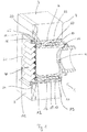
- Fig. 1 shows a sectional view of a wall duct with a first and second fluid guide body according to the invention.
- the wall bushing 1 is designed in several parts and has a first fluid guide body 10 and a second fluid guide body 20.
- the first fluid guide body 10 preferably has a guide 13, a first jacket 15, a guide space 12 and a receptacle 16 on its inner opening 11.
- the second fluid guide body 20 preferably has a second insert 22, a second jacket 25 and a peripheral second edge 26 at its outer opening 21.
- the second fluid guide body 20 can be introduced into the first fluid guide body 10, in particular into the guide space 12, and lies with an inner surface 24 of the second rim 26 preferably flat or flush on the outer side 5 of the building wall 3.
- the second fluid guide body 20 preferably has at its outer opening 21 a fluid-conducting cover device 40, which can be fastened to the second edge 26.
- an overlap region 60 partially forms between the second insert 22 and the guide 13 and / or the first jacket 15.
- the first fluid guide body 10 can be inserted into the second fluid guide body 20, whereby a closure in the overlap region 60 or at least partially made.
- the second insert 22 of the second fluid guide body 20 is preferably at most as long as the guide 13 of the first fluid guide body 10 is formed.
- the second slot 22 may be slightly shorter than the guide 13 may be formed when applied to the building wall 3 surface and / or Thermal insulation should have a smaller thickness. Incidentally, by a shorter execution of the second insert 22 material costs can be saved.
- the double wall of the first fluid guide body 10, which is formed in particular by the guide 13 and the first jacket 15, serves to form a stable connection between the two fluid guide bodies 10, 20 in an opening 2 of the building wall 3.
- the second shell 25 of the second fluid guide body 20 has a length which corresponds to the thickness of the surface and / or the thermal insulation on the building wall 3 or mostly.
- the first and second fluid guide body 10, 20 have a material thickness between 10 mm and 100 mm, in particular between 10 mm and 50 mm.
- first and second fluid guide bodies 10, 20 of the wall duct 1 preferably have square dimensions.
- first and second fluid guide body 10, 20 along a longitudinal axis 70 may also be made round.
- first and second fluid guide bodies 10, 20 may be rectangular, with an aspect ratio between 1: 1 and / or 1: 2.5.
- the first fluid guide body 10 has an outer geometry that adapts to the geometry of the opening in the building wall. Furthermore, the first fluid guide body 10 has an inner contour with an aerodynamic shape for optimum air guidance.
- the first fluid guide body 10 of the wall duct 1 is inserted from the inside 4 of the building wall 3 into the opening 2.
- the first fluid guide body 10 can be introduced from the outside 5 of the building wall 3 into the opening 2.
- the second fluid guide body 20 and / or a third fluid guide body (in Fig. 1 not shown) is preferably inserted from the outside 5 in the opening 2.
- first the first fluid guide body 10 and then the second fluid guide body 20 is inserted into the opening 2 of the building wall 3. If the final wall structure has not yet been reached, instead of the second fluid guide body 20, the third fluid guide body 30 is advantageously first inserted into the opening of the building wall 3 as a mounting aid.
- the third fluid guide body 30 can be used simultaneously with the first fluid guide body in the opening.
- the third fluid guide body can be timed before or after the time Insertion of the first fluid guide body 10 are inserted.
- the second fluid guide body 20 can be inserted into the opening 2 in time before the first fluid guide body 10 or at the same time as the first fluid guide body 10.
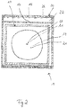
- Fig. 2 shows the front view of the second fluid guide body in the installed state according to Fig. 1 in a sketched schematic representation.
- the preferably square or rectangular wall duct 1 has different body edges.
- the second fluid guide body 20 is framed by the circumferential second edge 26 at the outer opening 21, to which the fluid-carrying cover device 40 can be fastened (in Fig. 2 not shown, but eg in Fig. 1 and Fig. 3 ).
- the outer opening 21 has the largest flow cross section A4.
- the second insert 22 is advantageously framed and / or bounded by a first jacket 15 and / or a guide 13, which has a flow cross-section A2. Since the first jacket 15 of the first fluid guide body 10 is not visible in the front view, are in Fig. 2 the hidden edges are shown in dashed lines.
- the inner opening 11 of the first fluid guide body 10 is preferably round and has over the multi-part wall duct 1, the smallest flow area A1.
- the transition of the rectangular or at least partially rectangular flow cross section to a round or at least partially round flow cross section serves to arrange a rectangular fluid-conducting cover device 40 on the outer opening 21 and a fluid line 6 of round cross section on the inner opening 11.
- first and second fluid guide body 10, 20 may be formed radially over the entire length of the wall duct 1 oval, in particular round.
- the embodiment according to the invention of a flow cross-section (A1-A4) which increases from the inner opening 11 to the outer opening 21 preferably serves to allow any condensate occurring inside the wall duct or penetrating moisture, such as driving rain, to drain easily from the outside at the outer opening.
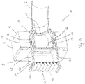
- Fig. 3 shows a sectional view of a wall duct consisting of a first and a third fluid guide body.
- the third fluid guide body 30 has a third one Sheath 35 on, which has a greater length than the second sheath 25, as in Fig. 1 shown.
- the plaster and / or the thermal insulation can be applied to the intended locations on the building wall 3 without restriction on a longer third shell 35.
- the third guide body 30 has a removable fluid separation wall 36, which is preferably formed on a base 37.
- the fluid separation wall 36 is disposed at the level of the outside 5 of the building wall 3.
- the closed supporting fluid separation wall 36 in the interior of the third fluid guide body 30 a stabilization and support of the wall bushing 1 is preferably achieved against deformations in the radial direction. Furthermore, the fluid separation wall 36 serves in particular to prevent an air passage through the wall duct 1, in particular in the installation phase of the wall duct 1. Optionally, the fluid separation wall 36 can be cut out, if a temporary air passage through the wall duct 1 is temporarily desired.
- the first and third fluid guide body 10, 30 preferably have a material thickness between 10 mm and 100 mm, in particular between 10 mm and 50 mm.
- Fig. 4 shows a schematic diagram of a fastening device for connecting the fluid-carrying cover to the outer opening.
- the fastening device 41 preferably has a basic framework 42, in particular in the form of an angle plate with at least one sleeve 43.
- the skeleton 42 preferably tensions an angle that corresponds or partially corresponds to the geometry of the second edge 26 and / or the second shell 25 (see FIG Fig. 1 ).
- the fastening device 41 is disposed in or on the second edge 26 of the second fluid guide body 20 and serves to receive and attach the fluid-carrying cover 40 at the outer opening 21.
- the skeleton 42 of the fastening device 41 with at least one sleeve 43 already in the manufacture of second fluid guide body 20 inserted into the second edge 26 of the second fluid guide body 20.
- the end 44 of the sleeve 43 is flush with the outer surface 27 of the second edge 26 from.
- the sleeve 43 is a threaded sleeve having an internal thread.
- the sleeve 43 designed as a threaded pin with external thread and protrudes for attachment with a fastener outside the outer surface 27 of the second edge 26 out.
- the sleeve 43 has a length which preferably corresponds to the material thickness of the second edge 26.
- the skeleton 42 is designed as a lightweight variant with recesses in the material.
- the number of required fastening devices - depending on the design of the second fluid guide body 20 - vary.
- at least two fastening devices are needed.
- four fastening devices can be used.
- longer angle plates with at least one sleeve, in particular two, preferably four, sleeves can be used in order to produce a uniform fit between the fluid-carrying cover device 40 and the second edge 26 of the second fluid guide body 20.
- the fastening device 41 may advantageously be formed from a one-piece round angle plate with at least two threaded sleeves.
- the round angle plate can be constructed in two parts or in several parts.
Landscapes
- Engineering & Computer Science (AREA)
- Chemical & Material Sciences (AREA)
- Combustion & Propulsion (AREA)
- Mechanical Engineering (AREA)
- General Engineering & Computer Science (AREA)
- Building Environments (AREA)
- Duct Arrangements (AREA)
- Ventilation (AREA)
Applications Claiming Priority (1)
| Application Number | Priority Date | Filing Date | Title |
|---|---|---|---|
| DE102017002396.4A DE102017002396A1 (de) | 2017-03-14 | 2017-03-14 | Wanddurchführung zum Anschluss an ein Haustechnikgerät und Verfahren zur Montage einer Wanddurchführung |
Publications (3)
| Publication Number | Publication Date |
|---|---|
| EP3376129A2 true EP3376129A2 (fr) | 2018-09-19 |
| EP3376129A3 EP3376129A3 (fr) | 2018-09-26 |
| EP3376129B1 EP3376129B1 (fr) | 2022-11-16 |
Family
ID=61569145
Family Applications (1)
| Application Number | Title | Priority Date | Filing Date |
|---|---|---|---|
| EP18160083.4A Active EP3376129B1 (fr) | 2017-03-14 | 2018-03-06 | Traversée de paroi destinée à la connexion à un appareil domestique et procédé de montage d'une traversée de paroi |
Country Status (2)
| Country | Link |
|---|---|
| EP (1) | EP3376129B1 (fr) |
| DE (1) | DE102017002396A1 (fr) |
Cited By (2)
| Publication number | Priority date | Publication date | Assignee | Title |
|---|---|---|---|---|
| EP4015931A1 (fr) * | 2020-12-17 | 2022-06-22 | Stiebel Eltron GmbH & Co. KG | Unité de traversée murale pour le branchement d'un appareil domotique |
| EP4293266A1 (fr) * | 2022-06-14 | 2023-12-20 | Naber Holding GmbH & Co. KG | Manchon de paroi pour un boîtier de mur, boîtier de mur et agencement d'un boîtier de mur et d'un mur |
Families Citing this family (3)
| Publication number | Priority date | Publication date | Assignee | Title |
|---|---|---|---|---|
| DE102020134041A1 (de) | 2020-12-17 | 2022-06-23 | Stiebel Eltron Gmbh & Co. Kg | Außenwandgitter für eine Wanddurchführungseinheit für den Anschluss eines Haustechnikgeräts |
| DE102022114506A1 (de) | 2022-06-09 | 2023-12-14 | Stiebel Eltron Gmbh & Co. Kg | Wanddurchführungseinheit und Wanddurchführungselement mit einer Adapterplatte |
| DE102023106138A1 (de) * | 2023-03-13 | 2024-09-19 | Airoluxx GmbH | Anschlussrahmen und Lüftungseinrichtung |
Family Cites Families (11)
| Publication number | Priority date | Publication date | Assignee | Title |
|---|---|---|---|---|
| DE1900060U (de) | 1964-05-15 | 1964-09-03 | Karl-Heinz Graefe | Verschlussstopfen fuer in unterputz verlegte wasserleitungen od. dgl. |
| AT281353B (de) | 1968-11-05 | 1970-05-25 | Vepa Vorrichtungsbau Emil Pfis | Kachelofen-einsatz |
| CH566470A5 (en) * | 1973-05-30 | 1975-09-15 | Vallotton Georges | Trans-wall duct for extraction of kitchen fumes - uses two telescoping plastics tubes to adjust to wall thickness and has outer louvred grille |
| DE7903055U1 (de) | 1979-02-05 | 1979-05-23 | Kiparski, Heinz, 4390 Gladbeck | Mauerkasten zum anschluss an das ende eines lueftungskanals |
| DE2945749C2 (de) * | 1979-11-13 | 1982-03-18 | Heinz 4390 Gladbeck Kiparski | Wandanschlußstück |
| US5257824A (en) | 1991-12-30 | 1993-11-02 | Eggen Harald I | Extender for a plumbing mount with spring loaded sealing piston |
| DE29719484U1 (de) * | 1997-11-03 | 1998-01-02 | Eslon B.V., Roermond | Ab- und Zuluftmauerkasten |
| DE102009057355B4 (de) * | 2009-12-07 | 2025-01-02 | Ventomaxx Gmbh | Lüftungseinrichtung zum Zuführen und/oder Abführen von Luft |
| DE202010002280U1 (de) | 2010-02-12 | 2010-09-09 | Henschke, Volker | Adapter zur Verbindung von Rauchgasleitungen mit unterschiedlichem Querschnitt |
| DE202010004800U1 (de) | 2010-04-09 | 2011-09-02 | Stiebel Eltron Gmbh & Co. Kg | Wanddurchführung für eine innen aufstellbare Wärmepumpenanlage |
| PL2887478T3 (pl) | 2013-12-20 | 2017-01-31 | Hauff-Technik Gmbh & Co. Kg | Montaż przewodu w elemencie ściennym lub podłogowym |
-
2017
- 2017-03-14 DE DE102017002396.4A patent/DE102017002396A1/de not_active Withdrawn
-
2018
- 2018-03-06 EP EP18160083.4A patent/EP3376129B1/fr active Active
Non-Patent Citations (1)
| Title |
|---|
| None |
Cited By (2)
| Publication number | Priority date | Publication date | Assignee | Title |
|---|---|---|---|---|
| EP4015931A1 (fr) * | 2020-12-17 | 2022-06-22 | Stiebel Eltron GmbH & Co. KG | Unité de traversée murale pour le branchement d'un appareil domotique |
| EP4293266A1 (fr) * | 2022-06-14 | 2023-12-20 | Naber Holding GmbH & Co. KG | Manchon de paroi pour un boîtier de mur, boîtier de mur et agencement d'un boîtier de mur et d'un mur |
Also Published As
| Publication number | Publication date |
|---|---|
| DE102017002396A1 (de) | 2018-09-20 |
| EP3376129B1 (fr) | 2022-11-16 |
| EP3376129A3 (fr) | 2018-09-26 |
Similar Documents
| Publication | Publication Date | Title |
|---|---|---|
| EP3376129B1 (fr) | Traversée de paroi destinée à la connexion à un appareil domestique et procédé de montage d'une traversée de paroi | |
| EP3913155B1 (fr) | Dispositif de protection de montage pour tuyauterie raccordée à la céramique sanitaire, ainsi que cadre de montage pour une céramique sanitaire doté d'un tel dispositif de protection de montage | |
| DE102010021245A1 (de) | Universalanschlussfitting | |
| EP2586934B1 (fr) | Boîte de raccordement de gicleur | |
| DE102014005312B4 (de) | Vorrichtung zum Fixieren von Plattenelementen und deren Verwendung | |
| EP2381150B1 (fr) | Unité d'étanchéité pour un passage de toiture ou de mur et procédé de fabrication d'un passage de toiture ou de mur | |
| DE102010012209A1 (de) | Anordnung zur Herstellung einer Anschlussmöglichkeit, insbesondere für einen Sprinkler an einer Beton- oder Stahlbetondecke, und Verfahren zur Herstellung einer derartigen Anschlussmöglichkeit | |
| DE8212628U1 (de) | Anschlussdose fuer eine wasserleitungsanlage | |
| DE102010034200A1 (de) | Abdichtung zur Einarbeitung für Flächenabdichtungen mit Fliesen im Verbund(II) | |
| EP2781842B1 (fr) | Revêtement de mur ou de plafond | |
| DE102013210798B3 (de) | Vorrichtung für eine Durchführung durch eine Wand eines Fertighauses sowie Verfahren zur Anbringung einer derartigen Durchführung an einem Bauelement eines Fertighauses | |
| AT503339A2 (de) | Gehäuse, insbesondere für heizungs-, lüftungs- oder klimageräte | |
| DE4040495C2 (fr) | ||
| DE202013104336U1 (de) | Dichtungsanordnung mit Kunststoffflansch | |
| DE202017007717U1 (de) | Wanddurchführung zum Anschluss an ein Haustechnikgerät | |
| DE202009017155U1 (de) | Bodenablauf für eine sanitäre Installation | |
| DE10227217B4 (de) | Unterflur-Bodendose | |
| EP3913154B1 (fr) | Dispositif de protection de montage pour tuyauterie raccordée à la céramique sanitaire, ainsi que cadre de montage pour une céramique sanitaire doté d'un tel dispositif de protection de montage | |
| DE102021106490B4 (de) | Schutzrohr für eine Hauseinführung und Mehrspartenhauseinführung | |
| DE102022114506A1 (de) | Wanddurchführungseinheit und Wanddurchführungselement mit einer Adapterplatte | |
| DE102017002395B4 (de) | Anschlussstutzen zum Anschluss an ein Haustechnikgerät und Verfahren zur Montage eines Anschlussstutzens | |
| DE10102882A1 (de) | Fugenprofil | |
| DE102011050428B4 (de) | Verkleidungsbausatz für ein Zentralstaubsaugersystem | |
| EP0410100A2 (fr) | Pièce tubulaire avec un espace interne pour la réception d'au moins une ligne | |
| EP2558762B1 (fr) | Raccordement entre un tuyau et un élément de tuyau |
Legal Events
| Date | Code | Title | Description |
|---|---|---|---|
| PUAI | Public reference made under article 153(3) epc to a published international application that has entered the european phase |
Free format text: ORIGINAL CODE: 0009012 |
|
| STAA | Information on the status of an ep patent application or granted ep patent |
Free format text: STATUS: THE APPLICATION HAS BEEN PUBLISHED |
|
| PUAL | Search report despatched |
Free format text: ORIGINAL CODE: 0009013 |
|
| AK | Designated contracting states |
Kind code of ref document: A2 Designated state(s): AL AT BE BG CH CY CZ DE DK EE ES FI FR GB GR HR HU IE IS IT LI LT LU LV MC MK MT NL NO PL PT RO RS SE SI SK SM TR |
|
| AX | Request for extension of the european patent |
Extension state: BA ME |
|
| AK | Designated contracting states |
Kind code of ref document: A3 Designated state(s): AL AT BE BG CH CY CZ DE DK EE ES FI FR GB GR HR HU IE IS IT LI LT LU LV MC MK MT NL NO PL PT RO RS SE SI SK SM TR |
|
| AX | Request for extension of the european patent |
Extension state: BA ME |
|
| RIC1 | Information provided on ipc code assigned before grant |
Ipc: F24F 13/02 20060101AFI20180820BHEP Ipc: F24F 7/00 20060101ALI20180820BHEP |
|
| STAA | Information on the status of an ep patent application or granted ep patent |
Free format text: STATUS: REQUEST FOR EXAMINATION WAS MADE |
|
| 17P | Request for examination filed |
Effective date: 20190326 |
|
| RBV | Designated contracting states (corrected) |
Designated state(s): AL AT BE BG CH CY CZ DE DK EE ES FI FR GB GR HR HU IE IS IT LI LT LU LV MC MK MT NL NO PL PT RO RS SE SI SK SM TR |
|
| STAA | Information on the status of an ep patent application or granted ep patent |
Free format text: STATUS: EXAMINATION IS IN PROGRESS |
|
| 17Q | First examination report despatched |
Effective date: 20200316 |
|
| GRAP | Despatch of communication of intention to grant a patent |
Free format text: ORIGINAL CODE: EPIDOSNIGR1 |
|
| STAA | Information on the status of an ep patent application or granted ep patent |
Free format text: STATUS: GRANT OF PATENT IS INTENDED |
|
| INTG | Intention to grant announced |
Effective date: 20220830 |
|
| GRAS | Grant fee paid |
Free format text: ORIGINAL CODE: EPIDOSNIGR3 |
|
| GRAA | (expected) grant |
Free format text: ORIGINAL CODE: 0009210 |
|
| STAA | Information on the status of an ep patent application or granted ep patent |
Free format text: STATUS: THE PATENT HAS BEEN GRANTED |
|
| AK | Designated contracting states |
Kind code of ref document: B1 Designated state(s): AL AT BE BG CH CY CZ DE DK EE ES FI FR GB GR HR HU IE IS IT LI LT LU LV MC MK MT NL NO PL PT RO RS SE SI SK SM TR |
|
| REG | Reference to a national code |
Ref country code: GB Ref legal event code: FG4D Free format text: NOT ENGLISH |
|
| REG | Reference to a national code |
Ref country code: CH Ref legal event code: EP |
|
| REG | Reference to a national code |
Ref country code: IE Ref legal event code: FG4D Free format text: LANGUAGE OF EP DOCUMENT: GERMAN |
|
| REG | Reference to a national code |
Ref country code: DE Ref legal event code: R096 Ref document number: 502018011032 Country of ref document: DE |
|
| REG | Reference to a national code |
Ref country code: AT Ref legal event code: REF Ref document number: 1531978 Country of ref document: AT Kind code of ref document: T Effective date: 20221215 |
|
| REG | Reference to a national code |
Ref country code: SE Ref legal event code: TRGR |
|
| REG | Reference to a national code |
Ref country code: LT Ref legal event code: MG9D |
|
| REG | Reference to a national code |
Ref country code: NL Ref legal event code: MP Effective date: 20221116 |
|
| PG25 | Lapsed in a contracting state [announced via postgrant information from national office to epo] |
Ref country code: PT Free format text: LAPSE BECAUSE OF FAILURE TO SUBMIT A TRANSLATION OF THE DESCRIPTION OR TO PAY THE FEE WITHIN THE PRESCRIBED TIME-LIMIT Effective date: 20230316 Ref country code: NO Free format text: LAPSE BECAUSE OF FAILURE TO SUBMIT A TRANSLATION OF THE DESCRIPTION OR TO PAY THE FEE WITHIN THE PRESCRIBED TIME-LIMIT Effective date: 20230216 Ref country code: LT Free format text: LAPSE BECAUSE OF FAILURE TO SUBMIT A TRANSLATION OF THE DESCRIPTION OR TO PAY THE FEE WITHIN THE PRESCRIBED TIME-LIMIT Effective date: 20221116 Ref country code: FI Free format text: LAPSE BECAUSE OF FAILURE TO SUBMIT A TRANSLATION OF THE DESCRIPTION OR TO PAY THE FEE WITHIN THE PRESCRIBED TIME-LIMIT Effective date: 20221116 Ref country code: ES Free format text: LAPSE BECAUSE OF FAILURE TO SUBMIT A TRANSLATION OF THE DESCRIPTION OR TO PAY THE FEE WITHIN THE PRESCRIBED TIME-LIMIT Effective date: 20221116 |
|
| PG25 | Lapsed in a contracting state [announced via postgrant information from national office to epo] |
Ref country code: RS Free format text: LAPSE BECAUSE OF FAILURE TO SUBMIT A TRANSLATION OF THE DESCRIPTION OR TO PAY THE FEE WITHIN THE PRESCRIBED TIME-LIMIT Effective date: 20221116 Ref country code: PL Free format text: LAPSE BECAUSE OF FAILURE TO SUBMIT A TRANSLATION OF THE DESCRIPTION OR TO PAY THE FEE WITHIN THE PRESCRIBED TIME-LIMIT Effective date: 20221116 Ref country code: LV Free format text: LAPSE BECAUSE OF FAILURE TO SUBMIT A TRANSLATION OF THE DESCRIPTION OR TO PAY THE FEE WITHIN THE PRESCRIBED TIME-LIMIT Effective date: 20221116 Ref country code: IS Free format text: LAPSE BECAUSE OF FAILURE TO SUBMIT A TRANSLATION OF THE DESCRIPTION OR TO PAY THE FEE WITHIN THE PRESCRIBED TIME-LIMIT Effective date: 20230316 Ref country code: HR Free format text: LAPSE BECAUSE OF FAILURE TO SUBMIT A TRANSLATION OF THE DESCRIPTION OR TO PAY THE FEE WITHIN THE PRESCRIBED TIME-LIMIT Effective date: 20221116 Ref country code: GR Free format text: LAPSE BECAUSE OF FAILURE TO SUBMIT A TRANSLATION OF THE DESCRIPTION OR TO PAY THE FEE WITHIN THE PRESCRIBED TIME-LIMIT Effective date: 20230217 |
|
| PGFP | Annual fee paid to national office [announced via postgrant information from national office to epo] |
Ref country code: SE Payment date: 20230314 Year of fee payment: 6 Ref country code: DE Payment date: 20230321 Year of fee payment: 6 |
|
| P01 | Opt-out of the competence of the unified patent court (upc) registered |
Effective date: 20230524 |
|
| PG25 | Lapsed in a contracting state [announced via postgrant information from national office to epo] |
Ref country code: NL Free format text: LAPSE BECAUSE OF FAILURE TO SUBMIT A TRANSLATION OF THE DESCRIPTION OR TO PAY THE FEE WITHIN THE PRESCRIBED TIME-LIMIT Effective date: 20221116 |
|
| PG25 | Lapsed in a contracting state [announced via postgrant information from national office to epo] |
Ref country code: SM Free format text: LAPSE BECAUSE OF FAILURE TO SUBMIT A TRANSLATION OF THE DESCRIPTION OR TO PAY THE FEE WITHIN THE PRESCRIBED TIME-LIMIT Effective date: 20221116 Ref country code: RO Free format text: LAPSE BECAUSE OF FAILURE TO SUBMIT A TRANSLATION OF THE DESCRIPTION OR TO PAY THE FEE WITHIN THE PRESCRIBED TIME-LIMIT Effective date: 20221116 Ref country code: EE Free format text: LAPSE BECAUSE OF FAILURE TO SUBMIT A TRANSLATION OF THE DESCRIPTION OR TO PAY THE FEE WITHIN THE PRESCRIBED TIME-LIMIT Effective date: 20221116 Ref country code: DK Free format text: LAPSE BECAUSE OF FAILURE TO SUBMIT A TRANSLATION OF THE DESCRIPTION OR TO PAY THE FEE WITHIN THE PRESCRIBED TIME-LIMIT Effective date: 20221116 Ref country code: CZ Free format text: LAPSE BECAUSE OF FAILURE TO SUBMIT A TRANSLATION OF THE DESCRIPTION OR TO PAY THE FEE WITHIN THE PRESCRIBED TIME-LIMIT Effective date: 20221116 |
|
| REG | Reference to a national code |
Ref country code: DE Ref legal event code: R097 Ref document number: 502018011032 Country of ref document: DE |
|
| PG25 | Lapsed in a contracting state [announced via postgrant information from national office to epo] |
Ref country code: SK Free format text: LAPSE BECAUSE OF FAILURE TO SUBMIT A TRANSLATION OF THE DESCRIPTION OR TO PAY THE FEE WITHIN THE PRESCRIBED TIME-LIMIT Effective date: 20221116 Ref country code: AL Free format text: LAPSE BECAUSE OF FAILURE TO SUBMIT A TRANSLATION OF THE DESCRIPTION OR TO PAY THE FEE WITHIN THE PRESCRIBED TIME-LIMIT Effective date: 20221116 |
|
| PLBE | No opposition filed within time limit |
Free format text: ORIGINAL CODE: 0009261 |
|
| STAA | Information on the status of an ep patent application or granted ep patent |
Free format text: STATUS: NO OPPOSITION FILED WITHIN TIME LIMIT |
|
| 26N | No opposition filed |
Effective date: 20230817 |
|
| PG25 | Lapsed in a contracting state [announced via postgrant information from national office to epo] |
Ref country code: MC Free format text: LAPSE BECAUSE OF FAILURE TO SUBMIT A TRANSLATION OF THE DESCRIPTION OR TO PAY THE FEE WITHIN THE PRESCRIBED TIME-LIMIT Effective date: 20221116 |
|
| GBPC | Gb: european patent ceased through non-payment of renewal fee |
Effective date: 20230306 |
|
| PG25 | Lapsed in a contracting state [announced via postgrant information from national office to epo] |
Ref country code: SI Free format text: LAPSE BECAUSE OF FAILURE TO SUBMIT A TRANSLATION OF THE DESCRIPTION OR TO PAY THE FEE WITHIN THE PRESCRIBED TIME-LIMIT Effective date: 20221116 |
|
| REG | Reference to a national code |
Ref country code: BE Ref legal event code: MM Effective date: 20230331 |
|
| PG25 | Lapsed in a contracting state [announced via postgrant information from national office to epo] |
Ref country code: LU Free format text: LAPSE BECAUSE OF NON-PAYMENT OF DUE FEES Effective date: 20230306 |
|
| REG | Reference to a national code |
Ref country code: IE Ref legal event code: MM4A |
|
| PG25 | Lapsed in a contracting state [announced via postgrant information from national office to epo] |
Ref country code: GB Free format text: LAPSE BECAUSE OF NON-PAYMENT OF DUE FEES Effective date: 20230306 |
|
| PG25 | Lapsed in a contracting state [announced via postgrant information from national office to epo] |
Ref country code: IE Free format text: LAPSE BECAUSE OF NON-PAYMENT OF DUE FEES Effective date: 20230306 Ref country code: GB Free format text: LAPSE BECAUSE OF NON-PAYMENT OF DUE FEES Effective date: 20230306 Ref country code: FR Free format text: LAPSE BECAUSE OF NON-PAYMENT OF DUE FEES Effective date: 20230331 |
|
| PG25 | Lapsed in a contracting state [announced via postgrant information from national office to epo] |
Ref country code: BE Free format text: LAPSE BECAUSE OF NON-PAYMENT OF DUE FEES Effective date: 20230331 |
|
| PG25 | Lapsed in a contracting state [announced via postgrant information from national office to epo] |
Ref country code: IT Free format text: LAPSE BECAUSE OF FAILURE TO SUBMIT A TRANSLATION OF THE DESCRIPTION OR TO PAY THE FEE WITHIN THE PRESCRIBED TIME-LIMIT Effective date: 20221116 |
|
| REG | Reference to a national code |
Ref country code: DE Ref legal event code: R119 Ref document number: 502018011032 Country of ref document: DE |
|
| REG | Reference to a national code |
Ref country code: SE Ref legal event code: EUG |
|
| PG25 | Lapsed in a contracting state [announced via postgrant information from national office to epo] |
Ref country code: BG Free format text: LAPSE BECAUSE OF FAILURE TO SUBMIT A TRANSLATION OF THE DESCRIPTION OR TO PAY THE FEE WITHIN THE PRESCRIBED TIME-LIMIT Effective date: 20221116 |
|
| PG25 | Lapsed in a contracting state [announced via postgrant information from national office to epo] |
Ref country code: BG Free format text: LAPSE BECAUSE OF FAILURE TO SUBMIT A TRANSLATION OF THE DESCRIPTION OR TO PAY THE FEE WITHIN THE PRESCRIBED TIME-LIMIT Effective date: 20221116 |
|
| PG25 | Lapsed in a contracting state [announced via postgrant information from national office to epo] |
Ref country code: DE Free format text: LAPSE BECAUSE OF NON-PAYMENT OF DUE FEES Effective date: 20241001 |
|
| PG25 | Lapsed in a contracting state [announced via postgrant information from national office to epo] |
Ref country code: DE Free format text: LAPSE BECAUSE OF NON-PAYMENT OF DUE FEES Effective date: 20241001 |
|
| PGFP | Annual fee paid to national office [announced via postgrant information from national office to epo] |
Ref country code: CH Payment date: 20250401 Year of fee payment: 8 |
|
| PG25 | Lapsed in a contracting state [announced via postgrant information from national office to epo] |
Ref country code: CY Free format text: LAPSE BECAUSE OF FAILURE TO SUBMIT A TRANSLATION OF THE DESCRIPTION OR TO PAY THE FEE WITHIN THE PRESCRIBED TIME-LIMIT; INVALID AB INITIO Effective date: 20180306 |
|
| PG25 | Lapsed in a contracting state [announced via postgrant information from national office to epo] |
Ref country code: HU Free format text: LAPSE BECAUSE OF FAILURE TO SUBMIT A TRANSLATION OF THE DESCRIPTION OR TO PAY THE FEE WITHIN THE PRESCRIBED TIME-LIMIT; INVALID AB INITIO Effective date: 20180306 |
|
| PG25 | Lapsed in a contracting state [announced via postgrant information from national office to epo] |
Ref country code: SE Free format text: LAPSE BECAUSE OF NON-PAYMENT OF DUE FEES Effective date: 20240307 |
|
| PG25 | Lapsed in a contracting state [announced via postgrant information from national office to epo] |
Ref country code: TR Free format text: LAPSE BECAUSE OF FAILURE TO SUBMIT A TRANSLATION OF THE DESCRIPTION OR TO PAY THE FEE WITHIN THE PRESCRIBED TIME-LIMIT Effective date: 20221116 |
|
| REG | Reference to a national code |
Ref country code: CH Ref legal event code: U11 Free format text: ST27 STATUS EVENT CODE: U-0-0-U10-U11 (AS PROVIDED BY THE NATIONAL OFFICE) Effective date: 20260401 |
|
| PGFP | Annual fee paid to national office [announced via postgrant information from national office to epo] |
Ref country code: AT Payment date: 20260320 Year of fee payment: 9 |