EP3376158A1 - Appareil de vérification de positionnement de pièces tubulaires métalliques, équipement de vérification et procédé de vérification de positionnement - Google Patents
Appareil de vérification de positionnement de pièces tubulaires métalliques, équipement de vérification et procédé de vérification de positionnement Download PDFInfo
- Publication number
- EP3376158A1 EP3376158A1 EP18382070.3A EP18382070A EP3376158A1 EP 3376158 A1 EP3376158 A1 EP 3376158A1 EP 18382070 A EP18382070 A EP 18382070A EP 3376158 A1 EP3376158 A1 EP 3376158A1
- Authority
- EP
- European Patent Office
- Prior art keywords
- casing
- verification apparatus
- positioning
- hole
- optical sensors
- Prior art date
- Legal status (The legal status is an assumption and is not a legal conclusion. Google has not performed a legal analysis and makes no representation as to the accuracy of the status listed.)
- Withdrawn
Links
Images





Classifications
-
- G—PHYSICS
- G01—MEASURING; TESTING
- G01B—MEASURING LENGTH, THICKNESS OR SIMILAR LINEAR DIMENSIONS; MEASURING ANGLES; MEASURING AREAS; MEASURING IRREGULARITIES OF SURFACES OR CONTOURS
- G01B11/00—Measuring arrangements characterised by the use of optical techniques
- G01B11/24—Measuring arrangements characterised by the use of optical techniques for measuring contours or curvatures
- G01B11/245—Measuring arrangements characterised by the use of optical techniques for measuring contours or curvatures using a plurality of fixed, simultaneously operating transducers
-
- B—PERFORMING OPERATIONS; TRANSPORTING
- B21—MECHANICAL METAL-WORKING WITHOUT ESSENTIALLY REMOVING MATERIAL; PUNCHING METAL
- B21C—MANUFACTURE OF METAL SHEETS, WIRE, RODS, TUBES, PROFILES OR LIKE SEMI-MANUFACTURED PRODUCTS OTHERWISE THAN BY ROLLING; AUXILIARY OPERATIONS USED IN CONNECTION WITH METAL-WORKING WITHOUT ESSENTIALLY REMOVING MATERIAL
- B21C31/00—Control devices for metal extruding, e.g. for regulating the pressing speed or temperature of metal; Measuring devices, e.g. for temperature of metal, combined with or specially adapted for use in connection with extrusion presses
-
- B—PERFORMING OPERATIONS; TRANSPORTING
- B21—MECHANICAL METAL-WORKING WITHOUT ESSENTIALLY REMOVING MATERIAL; PUNCHING METAL
- B21C—MANUFACTURE OF METAL SHEETS, WIRE, RODS, TUBES, PROFILES OR LIKE SEMI-MANUFACTURED PRODUCTS OTHERWISE THAN BY ROLLING; AUXILIARY OPERATIONS USED IN CONNECTION WITH METAL-WORKING WITHOUT ESSENTIALLY REMOVING MATERIAL
- B21C23/00—Extruding metal; Impact extrusion
- B21C23/21—Presses specially adapted for extruding metal
- B21C23/212—Details
- B21C23/215—Devices for positioning or centering press components, e.g. die or container
-
- B—PERFORMING OPERATIONS; TRANSPORTING
- B21—MECHANICAL METAL-WORKING WITHOUT ESSENTIALLY REMOVING MATERIAL; PUNCHING METAL
- B21C—MANUFACTURE OF METAL SHEETS, WIRE, RODS, TUBES, PROFILES OR LIKE SEMI-MANUFACTURED PRODUCTS OTHERWISE THAN BY ROLLING; AUXILIARY OPERATIONS USED IN CONNECTION WITH METAL-WORKING WITHOUT ESSENTIALLY REMOVING MATERIAL
- B21C23/00—Extruding metal; Impact extrusion
- B21C23/21—Presses specially adapted for extruding metal
- B21C23/217—Tube extrusion presses
-
- B—PERFORMING OPERATIONS; TRANSPORTING
- B21—MECHANICAL METAL-WORKING WITHOUT ESSENTIALLY REMOVING MATERIAL; PUNCHING METAL
- B21C—MANUFACTURE OF METAL SHEETS, WIRE, RODS, TUBES, PROFILES OR LIKE SEMI-MANUFACTURED PRODUCTS OTHERWISE THAN BY ROLLING; AUXILIARY OPERATIONS USED IN CONNECTION WITH METAL-WORKING WITHOUT ESSENTIALLY REMOVING MATERIAL
- B21C51/00—Measuring, gauging, indicating, counting, or marking devices specially adapted for use in the production or manipulation of material in accordance with subclasses B21B - B21F
-
- G—PHYSICS
- G01—MEASURING; TESTING
- G01B—MEASURING LENGTH, THICKNESS OR SIMILAR LINEAR DIMENSIONS; MEASURING ANGLES; MEASURING AREAS; MEASURING IRREGULARITIES OF SURFACES OR CONTOURS
- G01B11/00—Measuring arrangements characterised by the use of optical techniques
- G01B11/26—Measuring arrangements characterised by the use of optical techniques for measuring angles or tapers; for testing the alignment of axes
- G01B11/27—Measuring arrangements characterised by the use of optical techniques for measuring angles or tapers; for testing the alignment of axes for testing the alignment of axes
- G01B11/272—Measuring arrangements characterised by the use of optical techniques for measuring angles or tapers; for testing the alignment of axes for testing the alignment of axes using photoelectric detection means
Definitions
- the present application relates to a positioning and alignment verification apparatus for parts or components that intervene in an extrusion process of metal tubular pieces of an extruder press, in which each of said parts or components to be verified defines a central axis.
- the invention proposes the development of a verification apparatus for determining the positioning and alignment of different parts that intervene in the extrusion process carried out by means of extruder presses with tubular profiles or any other shape that include continuous puncturing, such as, for example, tubes, square or rectangular transverse cross section profiles, or any other profile that includes continuous puncturing.
- eccentricity is an indicative value of the concentricity of a tube and is calculated by measuring the thicknesses of the tube along the entire circumference thereof.
- verifier apparatuses are known in the state of the art, such as, for example, gauges with styli or other measuring apparatuses that are handled by an expert or an operator, wherein the alignments of each part that intervenes in the extrusion process of the presses are controlled through the contact of the stylus on the outer surface of the piece to be controlled, the alignment of which is to be verified.
- the present invention has been developed with the aim of providing a verifier apparatus that constitutes a novelty within the field of application, and solves the disadvantages mentioned above while also contributing other additional advantages, which will become evident from the description provided below.
- This apparatus is provided to verify the dimensions of the elements or pieces responsible for obtaining a tubular-shaped body from material in a melted state in a press, with the aim of predicting the value of eccentricity prior to the production of the tube to be manufactured, in order to correct and/or carry out the adjustments needed before producing the tubular body, thus avoiding problems in the process.
- an object of the present invention is to provide a positioning and alignment verification apparatus for different pieces and parts that intervene in the extrusion process of the extruder presses with tubular profiles of any type, profiles produced by extrusion having a continuous hole along the entire length of the extruded profile, which are circular or have any other profile that requires a constant and uniform thickness.
- the invention is characterized by the fact that it comprises a casing provided with a through hole through which the tubular piece to be verified, such as, for example, a puncturing mandrel of an extruder press, can be passed, in which said mandrel should be perfectly aligned and centered with regard to the rest of the parts that intervene in the extrusion process, including at least three light beam emitting optical sensors arranged in a stationary way and angularly equidistant in the casing, preferably inside the casing.
- the tubular piece to be verified such as, for example, a puncturing mandrel of an extruder press
- Said sensors are attached to a control unit through electrical connections, and they are arranged separately and radially around the through hole, such that the laser beam of each sensor is oriented towards the central longitudinal axis defined by the through hole. Furthermore, the casing comprises cooling means for cooling each of these optical sensors.
- a device is obtained to verify, for example, the coaxiality of the axis of the puncturing mandrel with a central axis of symmetry defined by the extruder press, where the verification is carried out in an "smart" way (in other words, with the help of software), such that it is not based on the personal criteria of an operator or qualified person, and therefore makes it possible to increase the degree of reliability during the verification process. Furthermore, this fact makes it possible to avoid physical contact between the verifying means and the puncturing mandrel to be verified via the use of means based on laser technology.
- This device is especially provided to be placed in the inlet area of an extruder machine, such that it makes it possible to verify the piece to be controlled (puncturing mandrel as it enters the container present in the extruder press).
- a laser beam to make the measurements is ideal for pieces which may be at 400oC in the extruder press, since they are not affected by the temperature unlike other measurement devices, where, due to the high temperature, components or parts (for example, probes) of the measurement apparatus may expand due to the temperature changes.
- the arrangement of the cooling means prevents the optical sensors from being damaged due to the overheating thereof caused by the temperature that the pieces of the extruder press to be verified may have; it provides a constant and suitable temperature at all times for the correct operation of the electronic components present inside the casing of the apparatus.
- the apparatus includes coupling means to couple the casing to the inlet area of the container of an extruder press with tubular profiles, such that the verification can be carried out at the machine.
- the cooling means comprise at least an inlet that can be connected to an external fluid supply source, for example, compressed or pressurized air at a pressure of 6 bars, as well as an outlet and channels present inside the casing attached to the inlet and the outlet, in order to circulate a fluid, there being channels with ends oriented towards the optical sensors.
- an external fluid supply source for example, compressed or pressurized air at a pressure of 6 bars
- the cooling means may comprise an insert that can be coupled to the casing which has a ring-shaped body that internally includes a hydraulic circuit provided with at least one inlet and one outlet for the liquid (such as, for example, water or another cooling liquid) to be circulated throughout the inside of the hydraulic circuit.
- a hydraulic circuit provided with at least one inlet and one outlet for the liquid (such as, for example, water or another cooling liquid) to be circulated throughout the inside of the hydraulic circuit.
- the apparatus may include sealing means located between two faces facing each other of the insert and the casing, which prevent the emergence of leaks of the cooling fluid that circulates through the insert towards the area of the casing where the optical sensors are located.
- the sealing means comprise toric joints arranged radially around the hydraulic circuit present inside the insert.
- each optical sensor is inside a housing that is located in recessed sections present inside the casing.
- each housing is comprised by a box-shaped structure that includes securing means to attach to the casing.
- the box structure is made from a plastic material resistant to high temperatures.
- plastic material may consist of Teflon® or Teflon-based plastic material, which is a plastic material known to have good thermal properties, in other words, withstand higher temperatures than other plastic materials.
- the casing that forms the outer part of the apparatus is comprised by two bodies that can be coupled together, which facilitates the mounting and maintenance of the components housed inside the casing.
- guide means present in each of the two front and rear casing bodies may be included.
- These guide means comprise a male-female system present in the inner face of each of the two bodies that form the casing.
- the casing may include securing means that will make it possible to handle the apparatus, for example, to transport it for the calibration thereof, maintenance tasks, etc.
- the securing means have an extension that protrudes from the casing that includes a through hole to allow a tool to pass through the through hole.
- the verification apparatus comprises four optical sensors arranged in a cruciform configuration around the through hole.
- the casing may have an elongated tubular prolongation that extends outwards which allows for the passage of ducts, such that it prevents these ducts from overheating due to the closeness of the tubular piece or extruder mandrel that is being verified.
- This is especially useful in tubular pieces of steel, copper, etc. where the protruding tube of the forming machine has a high temperature which could melt the ducts with continued heat exposure.
- Another aspect of the invention is to provide verification equipment that comprises a moveable table, a verification apparatus such as that described above and calibration means for calibrating the optical sensors present in the verification apparatus.
- the calibration means comprise a cylindrical body that protrudes from the top of a horizontal surface, the cylindrical body being arranged around positioning means of the casing that forms part of the verification apparatus.
- Said positioning means comprise a ring-shaped protruding element that protrudes from the horizontal surface and is arranged centrally with respect to the cylindrical body.
- Another object of the invention is to provide a positioning verification method, in particular, to verify the coaxiality of a puncturing mandrel of an extruder press with respect to a container of the extruder press itself, which comprises the following steps:
- the verification method may include a step for calibrating each optical sensor prior to the operation of the optical sensors.
- one embodiment of the alignment and concentricity verification apparatus for a puncturing mandrel of an extruder press of a ferromagnetic or non-ferromagnetic material comprises a metal casing provided with a through hole through which the puncturing mandrel of the extruder press can be passed.
- Said casing is comprised by two front and rear casing bodies (1, 2), respectively, that can be coupled together in a condition of use, including a male-female system present in the inner face of each of the two bodies that form the casing, which acts as guide means for facilitating the mounting of the two front and rear casing bodies (1, 2) during the manufacture of the apparatus described in this invention.
- lugs (15) present in a casing body which can be inserted in bores present in the other casing body facing it, are provided.
- the casing includes securing means that make it possible to facilitate the handling thereof by an operator manually or with the help of external means or tools.
- Said securing means have an extension (3) that protrudes from the body of the front casing (1) that includes a through hole (7) that facilitates the coupling of a tool (not shown), for example, a hook or other gripping means, through the through hole (4).
- One of the bodies of the casing has an elongated tubular prolongation (5) that extends outwards whereby the cables or electrical connections pass for the operation of the apparatus.
- the apparatus includes four laser beam emitting optical sensors (6), arranged in a stationary and cruciform way inside the housing, said sensors being equidistantly separated from each other.
- the optical sensor (6) used for this case is a class 1 model IL-3 laser sensor supplied by the commercial firm Keyence, with a measurement range of 20-45 mm with a margin of error of 1-5 ⁇ m.
- the optical sensors (6) are attached to a control unit through the electrical connections, preferably arranged separately and radially equidistant around the through hole (7), such that the laser beam of each sensor is oriented towards the central longitudinal axis defined by the through hole (7).
- the casing includes cooling means to cool each optical sensor that is explained below.
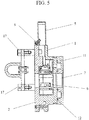
- these cooling means comprise at least one inlet (8) that can be connected to an external fluid supply source, one outlet (9) and channels present inside the casing attached to the inlet (8) and the outlet (9) to circulate a fluid, there being channels with hole-like ends oriented towards each optical sensor (6).
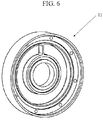
- the cooling means may be comprised of an insert (11) with a generally cylindrical shape that can be coupled to the front face of the casing body that has a ring-shaped body that internally includes a hydraulic circuit formed by ring-shaped slots in an inlet and an outlet for the liquid to be circulated throughout the inside of the hydraulic circuit.
- sealing means placed between two faces facing each other of the insert and the casing body comprising a pair of toric joints (12) separated from each other and arranged radially around the hydraulic circuit, as shown in Figure 5 .
- the sensors are placed inside a housing (13) that is located in recessed sections (14) present inside the front casing body (1).
- each housing (13) is comprised by a box-shaped structure made from Teflon material and defined by lateral walls that includes securing means to attach to the casing.
- the outer face of the rear casing body (2) includes coupling means to couple the casing to the inlet area or mouthpiece of the container of the extruder press.
- These coupling means are comprised by a series of projections (17) that protrude from the outer face of the rear casing body (2) which act as positioners that can be fit into specifically designed areas, for example, in the inlet area or mouthpiece of the container of the extruder press.
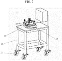
- verification equipment comprises a table (18) provided with a horizontal surface supported by vertical legs (21), with wheels (22) optionally provided at the bottom, which includes calibration means provided to calibrate the optical sensors present in the verification apparatus before operating and mounting the verification apparatus in the extruder press with tubes.
- the calibration means comprise a cylindrical body (23) that protrudes from the top of the horizontal surface (20) of the table (18), the cylindrical body being arranged around positioning means of the casing that forms part of the verification apparatus.
- the positioning means comprise a ring-shaped protruding element (24) that protrudes from the horizontal surface arranged centrally with respect to the cylindrical body (23).
- the calibration of the optical sensors present in the verification apparatus described above, prior to the use thereof in order to verify the positioning of metal tubular pieces, is carried out by the verification equipment described, which comprises the calibration means, through the following steps:
- the ideal distance between each laser beam emitting optical sensor (6) and the ring-shaped protruding element (24) is the distance at which all optical sensors (6) are found at the same distance with respect to the ring-shaped protruding element (24).
Landscapes
- Engineering & Computer Science (AREA)
- Mechanical Engineering (AREA)
- Physics & Mathematics (AREA)
- General Physics & Mathematics (AREA)
- Length Measuring Devices By Optical Means (AREA)
- Extrusion Of Metal (AREA)
- Extrusion Moulding Of Plastics Or The Like (AREA)
Applications Claiming Priority (1)
| Application Number | Priority Date | Filing Date | Title |
|---|---|---|---|
| ES201730365A ES2640093B2 (es) | 2017-03-17 | 2017-03-17 | Aparato de verificación de posicionamiento para piezas tubulares metálicas, equipo de verificación y método de verificación de posicionamiento |
Publications (1)
| Publication Number | Publication Date |
|---|---|
| EP3376158A1 true EP3376158A1 (fr) | 2018-09-19 |
Family
ID=60154218
Family Applications (1)
| Application Number | Title | Priority Date | Filing Date |
|---|---|---|---|
| EP18382070.3A Withdrawn EP3376158A1 (fr) | 2017-03-17 | 2018-02-08 | Appareil de vérification de positionnement de pièces tubulaires métalliques, équipement de vérification et procédé de vérification de positionnement |
Country Status (2)
| Country | Link |
|---|---|
| EP (1) | EP3376158A1 (fr) |
| ES (1) | ES2640093B2 (fr) |
Cited By (2)
| Publication number | Priority date | Publication date | Assignee | Title |
|---|---|---|---|---|
| CN113770192A (zh) * | 2020-06-09 | 2021-12-10 | 无锡市源昌机械制造有限公司 | 高精金属型材弯曲成型挤压模具 |
| CN116105638A (zh) * | 2023-03-24 | 2023-05-12 | 长春理工大学 | 一种u型转台同轴度检测系统及检测方法 |
Citations (4)
| Publication number | Priority date | Publication date | Assignee | Title |
|---|---|---|---|---|
| US5028798A (en) * | 1988-10-18 | 1991-07-02 | Sms Hasenclever Gmbh | Method and apparatus for determining the geometry of a body |
| US5094600A (en) * | 1989-12-21 | 1992-03-10 | Sikora Industrieelektronik Gmbh | Apparatus for measuring eccentricities of a rod of plastic material |
| US5421181A (en) * | 1992-09-12 | 1995-06-06 | Sms Hasenclever Gmbh | Horizontal metal extrusion press |
| EP0692697A2 (fr) * | 1994-07-12 | 1996-01-17 | Beta Instrument Company Limited | Jauge d'excentricité |
Family Cites Families (3)
| Publication number | Priority date | Publication date | Assignee | Title |
|---|---|---|---|---|
| US3808859A (en) * | 1971-08-05 | 1974-05-07 | Cefilac | Hydraulic presses |
| JPS63132716A (ja) * | 1986-11-21 | 1988-06-04 | Sumitomo Metal Ind Ltd | 押出機の偏芯測定装置 |
| ITUB20152138A1 (it) * | 2015-07-13 | 2017-01-13 | Presezzi Extrusion S P A | Dispositivo per il controllo automatico dell'eccentricita' di un mandrino in una pressa di estrusione |
-
2017
- 2017-03-17 ES ES201730365A patent/ES2640093B2/es active Active
-
2018
- 2018-02-08 EP EP18382070.3A patent/EP3376158A1/fr not_active Withdrawn
Patent Citations (4)
| Publication number | Priority date | Publication date | Assignee | Title |
|---|---|---|---|---|
| US5028798A (en) * | 1988-10-18 | 1991-07-02 | Sms Hasenclever Gmbh | Method and apparatus for determining the geometry of a body |
| US5094600A (en) * | 1989-12-21 | 1992-03-10 | Sikora Industrieelektronik Gmbh | Apparatus for measuring eccentricities of a rod of plastic material |
| US5421181A (en) * | 1992-09-12 | 1995-06-06 | Sms Hasenclever Gmbh | Horizontal metal extrusion press |
| EP0692697A2 (fr) * | 1994-07-12 | 1996-01-17 | Beta Instrument Company Limited | Jauge d'excentricité |
Cited By (3)
| Publication number | Priority date | Publication date | Assignee | Title |
|---|---|---|---|---|
| CN113770192A (zh) * | 2020-06-09 | 2021-12-10 | 无锡市源昌机械制造有限公司 | 高精金属型材弯曲成型挤压模具 |
| CN113770192B (zh) * | 2020-06-09 | 2024-01-16 | 无锡市源昌机械制造有限公司 | 高精金属型材弯曲成型挤压模具 |
| CN116105638A (zh) * | 2023-03-24 | 2023-05-12 | 长春理工大学 | 一种u型转台同轴度检测系统及检测方法 |
Also Published As
| Publication number | Publication date |
|---|---|
| ES2640093A8 (es) | 2017-11-14 |
| ES2640093A1 (es) | 2017-10-31 |
| ES2640093B2 (es) | 2018-04-24 |
Similar Documents
| Publication | Publication Date | Title |
|---|---|---|
| TWI673473B (zh) | 用於基板距離監控的面板、處理腔室及方法 | |
| CN104254759B (zh) | 用于在片材制造或处理系统中校正片材产品的卡尺厚度测量值的系统和方法 | |
| EP3376158A1 (fr) | Appareil de vérification de positionnement de pièces tubulaires métalliques, équipement de vérification et procédé de vérification de positionnement | |
| US20210162508A1 (en) | Internal defect detection system, three-dimensional additive manufacturing device, internal defect detection method, method of manufacturing three-dimensional additive manufactured product, and three-dimensional additive manufactured product | |
| CN109475917A (zh) | 径向偏移监测器 | |
| US10627204B2 (en) | Coefficient-of-thermal-expansion measurement method and measuring device for coefficient of thermal expansion | |
| US5094600A (en) | Apparatus for measuring eccentricities of a rod of plastic material | |
| EP3025844A1 (fr) | Appareil permettant de mesurer la température superficielle d'un produit moulée | |
| KR101005595B1 (ko) | 타이어 제조용 분할 금형의 진원도 측정 장지 | |
| US20020146478A1 (en) | Heated roller for a heating device for warming a film strip comprising thermoplastic plastic | |
| US9782925B2 (en) | Temperature probe | |
| KR102636172B1 (ko) | 반사 내부 링 | |
| US20110104418A1 (en) | Pre-marked building materials and method of manufacture | |
| US20110099827A1 (en) | Method for measuring a distance from a base surface to a tapering surface of a body | |
| JP5707150B2 (ja) | 成形材料の成形装置および成形材料の成形方法 | |
| US11897220B2 (en) | Method for measuring or calibrating utensils used in a press | |
| CN105479469B (zh) | 用于自动机械的正交定位装置、系统和方法 | |
| CN215725562U (zh) | 高效的螺栓检测装置 | |
| US20200055228A1 (en) | Method and device for producing profiled plastic sections | |
| Marcotuli et al. | Compensation of temperature effects on an automatic system for diameter measurement | |
| JP2018073862A5 (fr) | ||
| CA2729026A1 (fr) | Materiaux de construction pre-marques et procede de fabrication | |
| CN110763352B (zh) | 一种挤压筒装配后测温孔对齐的方法 | |
| CN115046519B (zh) | 定子直径测量装置及定子直径测量方法 | |
| KR101945411B1 (ko) | 축 정렬 장치 |
Legal Events
| Date | Code | Title | Description |
|---|---|---|---|
| PUAI | Public reference made under article 153(3) epc to a published international application that has entered the european phase |
Free format text: ORIGINAL CODE: 0009012 |
|
| STAA | Information on the status of an ep patent application or granted ep patent |
Free format text: STATUS: THE APPLICATION HAS BEEN PUBLISHED |
|
| AK | Designated contracting states |
Kind code of ref document: A1 Designated state(s): AL AT BE BG CH CY CZ DE DK EE ES FI FR GB GR HR HU IE IS IT LI LT LU LV MC MK MT NL NO PL PT RO RS SE SI SK SM TR |
|
| AX | Request for extension of the european patent |
Extension state: BA ME |
|
| RAP1 | Party data changed (applicant data changed or rights of an application transferred) |
Owner name: LA FARGA YOURCOPPERSOLUTIONS, S.A. |
|
| STAA | Information on the status of an ep patent application or granted ep patent |
Free format text: STATUS: REQUEST FOR EXAMINATION WAS MADE |
|
| 17P | Request for examination filed |
Effective date: 20190319 |
|
| STAA | Information on the status of an ep patent application or granted ep patent |
Free format text: STATUS: EXAMINATION IS IN PROGRESS |
|
| 17Q | First examination report despatched |
Effective date: 20210527 |
|
| STAA | Information on the status of an ep patent application or granted ep patent |
Free format text: STATUS: THE APPLICATION IS DEEMED TO BE WITHDRAWN |
|
| 18D | Application deemed to be withdrawn |
Effective date: 20211007 |