EP3376177B1 - Ultraschallflussmesser - Google Patents
Ultraschallflussmesser Download PDFInfo
- Publication number
- EP3376177B1 EP3376177B1 EP17160814.4A EP17160814A EP3376177B1 EP 3376177 B1 EP3376177 B1 EP 3376177B1 EP 17160814 A EP17160814 A EP 17160814A EP 3376177 B1 EP3376177 B1 EP 3376177B1
- Authority
- EP
- European Patent Office
- Prior art keywords
- ultrasonic
- measuring tube
- transducer
- protrusion
- ultrasonic flowmeter
- Prior art date
- Legal status (The legal status is an assumption and is not a legal conclusion. Google has not performed a legal analysis and makes no representation as to the accuracy of the status listed.)
- Active
Links
Images

Classifications
-
- G—PHYSICS
- G01—MEASURING; TESTING
- G01F—MEASURING VOLUME, VOLUME FLOW, MASS FLOW OR LIQUID LEVEL; METERING BY VOLUME
- G01F1/00—Measuring the volume flow or mass flow of fluid or fluent solid material wherein the fluid passes through a meter in a continuous flow
- G01F1/66—Measuring the volume flow or mass flow of fluid or fluent solid material wherein the fluid passes through a meter in a continuous flow by measuring frequency, phase shift or propagation time of electromagnetic or other waves, e.g. using ultrasonic flowmeters
- G01F1/662—Constructional details
-
- G—PHYSICS
- G01—MEASURING; TESTING
- G01F—MEASURING VOLUME, VOLUME FLOW, MASS FLOW OR LIQUID LEVEL; METERING BY VOLUME
- G01F1/00—Measuring the volume flow or mass flow of fluid or fluent solid material wherein the fluid passes through a meter in a continuous flow
- G01F1/66—Measuring the volume flow or mass flow of fluid or fluent solid material wherein the fluid passes through a meter in a continuous flow by measuring frequency, phase shift or propagation time of electromagnetic or other waves, e.g. using ultrasonic flowmeters
- G01F1/667—Arrangements of transducers for ultrasonic flowmeters; Circuits for operating ultrasonic flowmeters
Definitions
- This invention concerns to ultrasonic flowmeters for measuring a flowspeed or a volume flow of a medium through a measuring pipe.
- the patent application WO2014012707A1 for example describes such an ultrasonic flowmeter, wherein ultrasonic transducers are installed within a measuring tube in order to generate and/or sense ultrasonic pulses sent along a path through said measuring tube to a sensing transducer.
- the flow of a medium through said measuring tube influences the travel time of said pulses between said generating transducer and said sensing transducer dependent on the flow speed and on the flow direction of said medium.
- Important for any flowmeter is a good linearity between a measured flow and a real flow considering a flow range ranging from a slow medium to a fast medium. Unfortunately there are several disturbing effects which make the achievement of said linearity difficult.
- the region around the transducer, as lumps and bumps of said transducer as well as of a housing of said transducer may cause vortices of said medium close to the transducer such that the travel time of ultrasonic pulses may be heavily influenced.
- the influence of said vortices on the travel time of said pulses also show a complex dependency from flow speed.
- the patent application US 2015/0114134 A1 discloses an ultrasonic flowmeter with a shield protruding from the end face of the transducer, to reduce the influence of the vortices on the measurements.
- the problem to be solved by the invention is to reduce the influence of said vortices on the travel time of said ultrasonic pulses.
- This feature prevents a rotational flow around the transducer when said first and/or last subpath of said path is skew with said measuring tube axis.
- the asymmetric allocation of said housing and said transducer with respect to said measuring tube in this case causes a rotational flow in said gap which extends to a region in front of said end face creating a vortex of the medium in front of said end face. Suppressing said vortex with the help of said first protrusion improves the measurement performance of said ultrasonic flowmeter.
- the height of said first protrusion is at least 20% and especially at least 40% of said width of said gap. In order to provide a resistance for said rotational flow, the height of said first protrusion has to cross a least value.
- the height of said second protrusion is at least 20% and especially at least 40% of said width of said gap. In order to provide a resistance for said rotational flow, the height of said second protrusion has to cross a least value.
- a positioning of said first protrusion is tangentially offset to a positioning of said second protrusion.
- a ratio of said second diameter and said first diameter is within a first interval I1 or a second interval I2, wherein said intervals do not overlap, wherein an upper bound of said first interval is smaller than 1 and wherein a lower bound of said first interval is bigger than at least 0,87 and especially at least 0,90 and preferred at least 0,95, and wherein an upper bound of said second interval is bigger than 0,1 and wherein a lower bound of said second interval is smaller than 0,62 and especially smaller than 0,55 and preferred smaller than 0,52.
- the advantage of installing such a ratio is to place a vortex of the medium created at an edge of said housing and said measuring tube upstream of said end face aside of said end face.
- the complex behavior of said vortex dependent on the flow speed of said medium and the influence of said vortex on the travel time of said ultrasonic pulses is limited. It has been found, that the vortex is sufficiently spaced apart from said end face when arranging said ratio within said first interval or second interval.
- Said transducing element may be a piezoelectric element.
- Said transducer body may be fabricated out of one or more of following materials: steel, alumina, titanium, magnesium, glass, alloy comprising nickel and/or molybdenum and/or copper.
- a first and/or last subpath of said path is skew with said measuring tube axis.
- said first longitudinal axis and said second longitudinal axis are parallel to each other.
- said transducer body is axially symmetric with respect to said second longitudinal axis.
- said inner surface follows a cylindric shape.
- the fabrication of said measuring tube comprises welding and/or casting.
- said flowmeter comprises a multitude of said pairs of housings and said pairs of transducers.
- said flowmeter is set for flow measurement based on measuring a difference of a transit time of an ultrasonic pulse traveling upstream of said medium and a transit time of an ultrasonic pulse traveling downstream of said medium, and wherein within a range of flow speed of said medium along said measuring tube axis a relation between a real flow and a measured flow essentially follows a linear function of said real flow.
- a lower limit of said range is less than 10 m/s and especially less than 5 m/s and preferably less than 2,5 m/s and/or wherein an upper limit of said range is more than 20 m/s and especially more than 30 m/s and preferably more than 40 m/s.
- a deviation of said measured flow from said linear function is less than 3% and especially less than 1.5% and preferably less than 0.5% of said real flow.
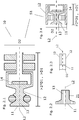
- Fig. 1 shows a schematic simplified longitudinal section of an ultrasonic flowmeter 1 comprising a measuring tube 20, a pair of ultrasonic transducers 10 each with a second longitudinal axis L2, which ultrasonic transducers 1 are each placed in a housing 22, which housings being included to the measuring tube, wherein each housing 22 has a first longitudinal axis L1.
- the housing has an inner first diameter D1
- a transducer body 13 of said ultrasonic transducer 10 in a region comprising an end face 11 exposable to a medium flowing through said measurement tube has a maximum second diameter D2 in a region comprising said end face 11.
- a flow break-away edge of an opening of said housing 22 towards said measuring tube 20 upstream of said end face 11 of said ultrasonic transducer 10 may cause a first vortex of said medium being located in front of said end face with a rotational axis approximately perpendicular to a first longitudinal axis of said housing.
- Ultrasonic pulses generated by a transducing element see Figs. 2.1 and 2.4 , for example a piezoelectric transducer, of said ultrasonic transducer and transferred by said end face into said medium will be influenced in case said first vortex is located in front of said end face.
- ultrasonic pulses having travelled along a path from a generating ultrasonic transducer to a sensing ultrasonic transducer of a pair of ultrasonic transducers will be influenced by a first vortex in front of said end face 11 of said sensing ultrasonic transducer 10.
- a typical ultrasonic transducer 10 has a second diameter D2 between 5 millimeters and 16 millimeters. Reference numerals shown only at one of the transducers 10 apply for the other transducer 10 as well.
- transducer body is symmetric with respect to said second longitudinal axis L2 and/or said housing follows a cylindrical shape with respect to said first longitudinal axis.
- a path of said ultrasonic pulses may be a more complex path including several subpath which may be skew with said measuring tube axis, or perpendicular or intercepting with said measuring tube axis.
- the considerations concerning said first protrusion P1 and said second protrusion P2 are valid as well if said path comprises several subpath, wherein a first and/or a last subpath is skew with said measuring tube axis.
- a rotational flow may be provoked inside a gap between a circumferential surface 12 of said transducer body 13 and said housing encompassing said circumferential surface at least partially. Said rotational flow may extend into said region comprising said end face 11 creating a second vortex with a rotational axis approximately perpendicular to said end face 11 influencing said ultrasonic pulses.
- said transducer body 13 comprises at least a first protrusion P1 protruding into said gap or/and said housing 22 comprises at least a second protrusion P2 protruding into said gap, which protrusions increase a flow resistance for said rotational flow inside said gap.
- said ultrasonic flowmeter 1 comprises both, at least one first protrusion and at least one second protrusion, a positioning of said first protrusion is tangentially offset to a positioning of said second protrusion.
- Said ultrasonic flowmeter 1 may comprise only at least one first protrusion and/or at least one second protrusion without installing a certain ratio of said second diameter D2 and said first diameter D1.
- Said housing 22 may be welded to said measuring tube. However, the measuring tube and said housing 22 may be fabricated at the same time by casting.
- Said ultrasonic flowmeter 1 further comprises an electronic circuit 80 for operating said ultrasonic transducers and for evaluating of sensed ultrasonic pulses, wherein said electronic circuit 80 is connected to said transducers via cable connections (not shown).
- Said ultrasonic flowmeter 1 may comprise several pair of transducers 10 for measuring the flow of said medium with several ultrasonic pulse paths. Said path do not necessarily have a similar shape.
- Figs. 2.1 - 2.4 show more detailed longitudinal sections of said first sector S1 of exemplary ultrasonic transducers 10 according to the invention comprising said end face 11 of said transducer body 13.
- Fig. 2.1 shows said first sector S1 comprising said ultrasonic transducer body 13, wherein a radial extension of said circumferential surface 12 decreases in a frontal part with increasing distance from said end face 11 such that said transducer body comprises within said frontal part a conically shaped section.
- An ultrasonic transducer according to the invention may comprise one or more damping rings surrounding said transducer body 13 as sketched by two round shapes.
- Said transducer body 13 may comprise a chamber for housing said transducing element 14.
- Said transducer body 13 with increasing distance to said end face 11 may further comprise one or more widenings.
- said second diameter D2 is a maximum diameter of said transducer within an area of said ultrasonic transducer 10 comprising said end face 11 along said second longitudinal axis L2 within a range of less than two times said first diameter D1 and preferably less than D1 from said end face 11.
- D2 is a maximum diameter of the transducer within said range.
- said second diameter D2 is the diameter of said widenings.
- said second diameter D2 is determined by the radial extension of said chamber.
- said second diameter D2 may be determined by said damping ring or by said end face 11.
- Fig. 2.2 shows an alternative embodiment of said frontal part of said ultrasonic transducer body 13 as shown in Fig. 2.1 , wherein a radial extension of said circumferential surface 12 decreases in a section with increasing distance from said end face 11 wherein the decreasing is nonlinear.
- Fig. 2.3 shows an alternative embodiment of said frontal part of said ultrasonic transducer body 13 as shown in Fig. 2.1 , wherein a radial extension of said circumferential surface 12 is mainly constant.
- Fig. 2.4 shows a first sector of another embodiment of said ultrasonic transducer with a chamber for housing said transducing element as shown in Fig. 2.1 further comprising a protecting sleeve and a sealing/damping-element, wherein said ultrasonic transducer body 13 is surrounded by said protecting sleeve at least partially, wherein said sealing/damping-element is arranged in order to seal said chamber from said medium.
- relevant for a determination of said second diameter D2 is a maximum diameter of said transducer within a range of less than two times said first diameter D1 and preferably less than D1 from said end face 11.
- D2 is a maximum diameter of the transducer within said range.
- said second diameter D2 is a maximum outer diameter of said protecting sleeve such that said circumferential surface is a surface of said protecting sleeve.
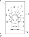
- Fig. 3 shows a simplified front view of an ultrasonic transducer according to the invention from a direction A as shown in Fig. 1 , wherein said end face 11 of said ultrasonic transducer, four first protrusions P1 of said transducer 10 and four second protrusions P2 of said housing 22 are shown, and wherein the positioning of said first protrusion P1 is tangentially offset to a positioning of said second protrusion P2.
- the first protrusions are placed on said circumferential surface 12.
- the first and/or second protrusions have a height of at least 20% and especially at least 40% of said width of said gap. This may also be valid for an ultrasonic flowmeter with any number of first protrusions P1 and second protrusions P2.
- said protrusions have a height less than 90 % of said width of said gap in order to avoid coupling between said transducer body and said housing due to formation of droplets due to condensation of said medium or a component of said medium at an edge of said protrusions. It is advantageous if a tangential distance of said first protrusions P1 to each other is essentially constant. It is advantageous if a tangential distance of said second protrusions P2 to each other is essentially constant.
- the gap is surrounded by a measuring tube wall 21.
- said ultrasonic transducer may comprise a protecting sleeve.
- the radial extension of said end face 11 is limited to the dashed circle such that said circumferential surface is a surface of said protecting sleeve.
- the at least one first protrusion is placed within said first sector and preferably placed on an outer side of said chamber.
- said at least one first projection is placed on an outer side of said protection sleeve.
- An ultrasonic transducer according to the invention however does not necessarily need both, first protrusions and second protrusion.
- Such an ultrasonic transducer may also comprise only a first protrusion, or a second protrusion or no protrusions at all.
- a relation between a real flow and a measured flow is essentially linear in a flow range wherein a lower limit of said flow range is less than 10 m/s and especially less than 5 m/s and preferably less than 2,5 m/s and/or wherein an upper limit of said range is more than 20 m/s and especially more than 30 m/s and preferably more than 40 m/s.
- a deviation of said measured flow from said linear function is less than 3% and especially less than 1.5% and preferably less than 0.5% of said real flow.
- the application of said ratio of said second diameter D2 and said first diameter D1 and/or said first protrusion P1 and/or said second protrusion P2 helps for obtaining an essentially linear relation between said absolute deviation of said measured flow from said real flow and said real flow within said flow range, wherein said flowmeter is set for flow measurement based on measuring a difference of a transit time of an ultrasonic pulse traveling upstream of said medium and a transit time of an ultrasonic pulse traveling downstream of said medium.
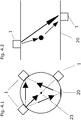
- Figs. 4.1 and 4.2 sketch different signal path between a pair of transducers with one or two signal subpath, wherein Fig. 4.1 shows a frontal projection of said signal path, and wherein Fig. 4.2 shows a side projection of said signal path.
- Fig. 4.1 sketches three signal path, wherein a first signal path is a direct signal path between a pair of ultrasonic transducers such that said signal path is a first sub path and a last subpath, wherein said signal is skew with said measuring tube axis.
- a second signal path is also a direct path crossing said measuring tube axis 23.
- a third signal path comprises a first subpath between a generating transducer and a reflecting element and a second subpath between said second element and a receiving transducer.
- the reflecting element may be said measuring tube wall or a mirror installed on said measuring tube wall.
- a signal path may be extended such that it comprises more than two signal subpath.
- Fig. 4.2 sketches a side projection of a direct subpath crossing a measuring tube axis and of a signal path comprising two subpath being reflected once at an reflecting element, which may be said measuring tube wall or a mirror installed on said measuring tube wall.
Landscapes
- Physics & Mathematics (AREA)
- Electromagnetism (AREA)
- Fluid Mechanics (AREA)
- General Physics & Mathematics (AREA)
- Measuring Volume Flow (AREA)
Claims (14)
- Ultraschall-Durchflussmessgerät (1) für die Messung des Durchflusses eines durch ein Messrohr fließenden Mediums basierend auf dem Prinzip der Laufzeitdifferenz, Folgendes umfassend:Ein Messrohr (20) mit einer Messrohrwand (21) für die Leitung besagten Mediums und mindestens einem sich zu einer äußeren Seite besagter Messrohrwand erstreckenden Gehäusepaar (22);mindestens ein Paar Ultraschall-Messumformer (10) mit jeweils einem Umformelement (14) für die Erzeugung und/oder die Erfassung von Ultraschallimpulsen und ein Umformerkörper (13) mit besagtem Umformungselement, wobei sich besagte Ultraschallimpulse zwischen besagten Messumformern entlang eines Weges bewegen, wobei mindestens ein Teilweg eines Weges, der sich zwischen dem besagten Paar Messumformer erstreckt, nicht parallel zu einer Messrohrachse besagten Messrohrs (20) ist;eine elektronische Schaltung (80) für den Betrieb besagter Ultraschall-Messumformer und für die Auswertung der erfassten Ultraschallimpulse;wobei jedes der besagten Gehäuse (22) so angeordnet ist, dass einer der besagten Messumformer (10) darin aufgenommen wird, und wobei besagte Gehäuse (22) eine Innenfläche und eine erste Längsachse (L1) und einen inneren ersten Durchmesser (D1), der orthogonal zu besagter erster Längsachse ist, umfassen;wobei besagter Messumformer (10) eine umlaufende Fläche (12) umfasst,und wobei besagter Umformerkörper (13) eine zweite Längsachse (L2) umfasst, und wobei besagter Messumformer (10) eine Endfläche (11), die besagtem Medium ausgesetzt werden kann, umfasst, wobei besagte Endfläche (11) für die Übertragung besagter Ultraschallimpulse zwischen dem besagten Umformerelement (14) und dem besagten Medium und umgekehrt eingerichtet ist, und wobei ein erster Abschnitt (S1) des besagten Messumformers, der die besagte Endfläche des besagten Umformerkörpers umfasst, einen maximalen zweiten Durchmesser (D2), der orthogonal zu der besagten zweiten Längsachse (L2) ist, aufweist,und wobei das besagte Gehäuse die besagte umlaufende Fläche (12) mindestens teilweise umschließt,dadurch gekennzeichnet, dassbesagter Messumformer mindestens einen ersten Überstand (P1), der aus besagter umlaufenden Fläche (12) in eine Lücke zwischen besagtem Umformerkörper (13) und besagtem Gehäuse (22) ragt, umfasst, wobei eine Höhe des ersten Überstands (P1) kleiner als die Breite der besagten Lücke ist,und/oderdass besagtes Gehäuse mindestens einen zweiten Überstand (P2), der in besagte Lücke ragt, umfasst, wobei eine Höhe des zweiten Überstands kleiner als die Breite der besagten Lücke ist.
- Ultraschall-Durchflussmessgerät nach Anspruch 1,
wobei die Höhe des besagten ersten Überstands mindestens 20 % und insbesondere mindestens 40 % der besagten Breite der besagten Lücke entspricht. - Ultraschall-Durchflussmessgerät nach Anspruch 1 oder 2,
wobei die Höhe des besagten zweiten Überstands mindestens 20 % und insbesondere mindestens 40 % der besagten Breite der besagten Lücke entspricht. - Ultraschall-Durchflussmessgerät nach einem der vorhergehenden Ansprüche, wobei eine Positionierung des besagten Überstands tangential zu einer Positionierung des besagten zweiten Überstands versetzt ist.
- Ultraschall-Durchflussmessgerät nach einem der vorhergehenden Ansprüche, wobei ein Verhältnis des besagten zweiten Durchmessers (D2) und des besagten ersten Durchmessers (D1) innerhalb eines ersten Intervalls I1 oder eines zweiten Intervalls I2 liegt, wobei besagte Intervalle nicht überlappen,
wobei eine obere Grenze des besagten ersten Intervalls kleiner als 1 ist und wobei eine untere Grenze des besagten ersten Intervalls größer als mindestens 0,87 und insbesondere mindestens 0,90 und vorzugsweise mindestens 0,95 ist,
und wobei eine obere Grenze des besagten zweiten Intervalls größer als 0,1 ist und wobei eine untere Grenze des besagten zweiten Intervalls kleiner als 0,62 und insbesondere kleiner als 0,55 und vorzugsweise kleiner als 0,52 ist. - Ultraschall-Durchflussmessgerät nach einem der vorhergehenden Ansprüche, wobei ein erster und/oder letzter Teilweg des besagten Weges schräg zur besagten Messrohrachse verläuft.
- Ultraschall-Durchflussmessgerät nach einem der vorhergehenden Ansprüche, wobei die besagte erste Längsachse (L1) und die besagte zweite Längsachse (L2) parallel zueinander sind.
- Ultraschall-Durchflussmessgerät nach einem der vorhergehenden Ansprüche, wobei besagter Umformerkörper axialsymmetrisch in Bezug auf die besagte zweite Längsachse ist.
- Ultraschall-Durchflussmessgerät nach einem der vorhergehenden Ansprüche, wobei besagte Innenfläche einer zylindrischen Form entspricht.
- Ultraschall-Durchflussmessgerät nach einem der vorhergehenden Ansprüche, wobei die Herstellung des besagten Messrohrs Schweiß- und/oder Gussarbeiten umfasst.
- Ultraschall-Durchflussmessgerät nach einem der vorhergehenden Ansprüche, wobei besagtes Durchflussmessgerät (1) eine Vielzahl an besagten Gehäusepaaren und besagten Messumformerpaaren umfasst.
- Ultraschall-Durchflussmessgerät nach einem der vorhergehenden Ansprüche, wobei besagtes Durchflussmessgerät (1) für die Durchflussmessung basierend auf der Messung einer Differenz einer Laufzeit eines Ultraschallimpuls, der sich entgegen der Stromrichtung des besagten Mediums bewegt, und einer Laufzeit eines Ultraschallimpuls, der sich in Stromrichtung des besagten Mediums bewegt, eingerichtet ist, und wobei innerhalb eines Bereichs der Durchflussgeschwindigkeit des besagten Mediums entlang der besagten Messrohrachse ein Verhältnis zwischen einem tatsächlichen Durchfluss und einem gemessen Durchfluss im Wesentlichen einer linearen Funktion des besagten tatsächlichen Durchflusses folgt.
- Ultraschall-Durchflussmessgerät nach Anspruch 12,
wobei ein unterer Grenzwert des besagten Bereichs niedriger als 10 m/s und insbesondere niedriger als 5 m/s und vorzugsweise niedriger als 2,5 m/s ist und/oder wobei ein oberer Grenzwert des besagten Bereichs höher als 20 m/s und insbesondere höher als 30 m/s and vorzugsweise höher als 40 m/s ist. - Ultraschall-Durchflussmessgerät nach Anspruch 12 oder 13,
wobei eine Abweichung des besagten gemessenen Durchflusses von besagter linearer Funktion weniger als 3 % und insbesondere weniger als 1,5 % und vorzugsweise weniger als 0,5 % des besagten tatsächlichen Durchflusses entspricht.
Priority Applications (4)
| Application Number | Priority Date | Filing Date | Title |
|---|---|---|---|
| EP17160814.4A EP3376177B1 (de) | 2017-03-14 | 2017-03-14 | Ultraschallflussmesser |
| CN201880016082.5A CN110383013B (zh) | 2017-03-14 | 2018-02-15 | 超声流量计 |
| PCT/EP2018/053779 WO2018166742A1 (en) | 2017-03-14 | 2018-02-15 | Ultrasonic flowmeter |
| US16/493,383 US10895479B2 (en) | 2017-03-14 | 2018-02-15 | Ultrasonic flowmeter |
Applications Claiming Priority (1)
| Application Number | Priority Date | Filing Date | Title |
|---|---|---|---|
| EP17160814.4A EP3376177B1 (de) | 2017-03-14 | 2017-03-14 | Ultraschallflussmesser |
Publications (2)
| Publication Number | Publication Date |
|---|---|
| EP3376177A1 EP3376177A1 (de) | 2018-09-19 |
| EP3376177B1 true EP3376177B1 (de) | 2019-11-20 |
Family
ID=58347136
Family Applications (1)
| Application Number | Title | Priority Date | Filing Date |
|---|---|---|---|
| EP17160814.4A Active EP3376177B1 (de) | 2017-03-14 | 2017-03-14 | Ultraschallflussmesser |
Country Status (4)
| Country | Link |
|---|---|
| US (1) | US10895479B2 (de) |
| EP (1) | EP3376177B1 (de) |
| CN (1) | CN110383013B (de) |
| WO (1) | WO2018166742A1 (de) |
Families Citing this family (8)
| Publication number | Priority date | Publication date | Assignee | Title |
|---|---|---|---|---|
| US11590535B2 (en) * | 2017-10-25 | 2023-02-28 | Honeywell International Inc. | Ultrasonic transducer |
| GB201808918D0 (en) * | 2018-05-31 | 2018-07-18 | Sentec Ltd | Flow measurement improvement |
| US12460958B2 (en) | 2019-02-22 | 2025-11-04 | Onesubsea Ip Uk Limited | Flowmeter with attenuating ribbed transducer housings |
| US12320777B2 (en) | 2019-02-22 | 2025-06-03 | Onesubsea Ip Uk Limited | Oilfield production particulate monitoring assembly |
| US12320686B2 (en) | 2019-02-22 | 2025-06-03 | Onesubsea Ip Uk Limited | Flowmeter with attenuating ribbed transducer housings |
| EP3889552B1 (de) * | 2020-04-03 | 2023-08-02 | SICK Engineering GmbH | Durchflussmessgerät |
| EP3964801B1 (de) * | 2020-09-08 | 2024-12-25 | Kamstrup A/S | Durchflussrohr mit ultraschalldurchflussmesser und verfahren zur herstellung des durchflussrohres |
| CN119618328B (zh) * | 2024-11-28 | 2025-11-14 | 山西科达信创科技有限公司 | 一种具有漏水检测功能的超声波水表 |
Citations (1)
| Publication number | Priority date | Publication date | Assignee | Title |
|---|---|---|---|---|
| US20130283930A1 (en) * | 2010-12-21 | 2013-10-31 | Endress + Hauser Flowtec Ag | Ultrasonic, Flow Measuring Device |
Family Cites Families (11)
| Publication number | Priority date | Publication date | Assignee | Title |
|---|---|---|---|---|
| US3906791A (en) * | 1973-10-01 | 1975-09-23 | Panametrics | Area averaging ultrasonic flowmeters |
| JP3669580B2 (ja) * | 2002-05-24 | 2005-07-06 | 学校法人慶應義塾 | 超音波流速分布及び流量計 |
| JP4033341B2 (ja) * | 2002-09-30 | 2008-01-16 | 本多電子株式会社 | 超音波流量計センサ |
| CN101672671A (zh) * | 2009-10-14 | 2010-03-17 | 江苏迈拓智能仪表有限公司 | 超声流量、热量表换能器用z型管段 |
| US8181534B2 (en) | 2010-01-06 | 2012-05-22 | Daniel Measurement And Control, Inc. | Ultrasonic flow meter with transducer assembly, and method of manufacturing the same while maintaining the radial position of the piezoelectric element |
| WO2011119596A2 (en) * | 2010-03-25 | 2011-09-29 | Daniel Measurement And Control, Inc. | Ultrasonic flow meter with liquid drainage system |
| CN102062623B (zh) | 2010-11-09 | 2012-06-20 | 郭荣岭 | 消除零点误差的超声波流量计 |
| EP2696174A4 (de) * | 2011-04-05 | 2014-08-27 | Panasonic Corp | Ultraschall-flussratenmessvorrichtung |
| DE102012013916A1 (de) | 2012-07-16 | 2014-01-16 | Endress + Hauser Flowtec Ag | Ultraschall-Durchflussmessgerät |
| PL2888560T3 (pl) * | 2012-08-22 | 2023-08-21 | Apator Miitors Aps | Kompaktowy przepływomierz ultradźwiękowy |
| DE102014004747B4 (de) * | 2013-10-30 | 2023-02-16 | Krohne Ag | Ultraschall-Durchflussmesser |
-
2017
- 2017-03-14 EP EP17160814.4A patent/EP3376177B1/de active Active
-
2018
- 2018-02-15 CN CN201880016082.5A patent/CN110383013B/zh active Active
- 2018-02-15 US US16/493,383 patent/US10895479B2/en active Active
- 2018-02-15 WO PCT/EP2018/053779 patent/WO2018166742A1/en not_active Ceased
Patent Citations (1)
| Publication number | Priority date | Publication date | Assignee | Title |
|---|---|---|---|---|
| US20130283930A1 (en) * | 2010-12-21 | 2013-10-31 | Endress + Hauser Flowtec Ag | Ultrasonic, Flow Measuring Device |
Also Published As
| Publication number | Publication date |
|---|---|
| WO2018166742A1 (en) | 2018-09-20 |
| CN110383013B (zh) | 2021-03-12 |
| US20200072649A1 (en) | 2020-03-05 |
| CN110383013A (zh) | 2019-10-25 |
| EP3376177A1 (de) | 2018-09-19 |
| US10895479B2 (en) | 2021-01-19 |
Similar Documents
| Publication | Publication Date | Title |
|---|---|---|
| US10895479B2 (en) | Ultrasonic flowmeter | |
| CN107735652B (zh) | 包括测量通道和副通道的流量计 | |
| US6101885A (en) | Substitution kits for volumetric flow sensors and corresponding vortex flow sensors | |
| US9506788B2 (en) | Ultrasonic flowmeter having a transducer housing with an ultrasound window which is mounted in a transducer pocket, and a shielding for protecting the ultrasonic signal path from the effects of vortices generated by the transducer pocket | |
| CN102483339A (zh) | 流体流量调节器 | |
| CN108027260B (zh) | 用于传感器的传感器组件、传感器以及用其制造的测量系统 | |
| CA2778063C (en) | Accessory apparatus for flowmeters | |
| US5913247A (en) | Transducer for a vortex flowmeter | |
| US5922970A (en) | Vortex flow sensor with a turbulence grid | |
| JP3100926B2 (ja) | 乱流格子を備えた渦流センサ | |
| EP3376178A1 (de) | Ultraschallflussmesser | |
| JP4693990B2 (ja) | パイプ内の液体の流量を測定するための装置 | |
| CN112050874A (zh) | 超声波流量测量计、其在闭塞器具中的使用和闭塞器具 | |
| CN112050876B (zh) | 超声流量测量仪、超声流量测量仪在闭塞机构中的应用和闭塞机构 | |
| JP2005502038A (ja) | 渦流ピックアップ | |
| CN111566453B (zh) | 根据旋涡测量原理的流量计装置、用于其的测量管和用于测量介质的流量或流速的方法 | |
| JP4411917B2 (ja) | 渦流量計 | |
| EP3574290B1 (de) | Vortex-durchflussmesselement zum einführen | |
| RU2162206C2 (ru) | Вихревой счетчик текучей среды | |
| JP2024522957A (ja) | 流量計 | |
| JP3270171B2 (ja) | フルイディック流量計 | |
| US20190368905A1 (en) | Magnetic-inductive flowmeter and measuring tube | |
| JP2984689B2 (ja) | 流体量計 | |
| RU2149360C1 (ru) | Вихревой преобразователь расхода | |
| JPS63269018A (ja) | 渦流量計 |
Legal Events
| Date | Code | Title | Description |
|---|---|---|---|
| PUAI | Public reference made under article 153(3) epc to a published international application that has entered the european phase |
Free format text: ORIGINAL CODE: 0009012 |
|
| STAA | Information on the status of an ep patent application or granted ep patent |
Free format text: STATUS: THE APPLICATION HAS BEEN PUBLISHED |
|
| AK | Designated contracting states |
Kind code of ref document: A1 Designated state(s): AL AT BE BG CH CY CZ DE DK EE ES FI FR GB GR HR HU IE IS IT LI LT LU LV MC MK MT NL NO PL PT RO RS SE SI SK SM TR |
|
| AX | Request for extension of the european patent |
Extension state: BA ME |
|
| STAA | Information on the status of an ep patent application or granted ep patent |
Free format text: STATUS: REQUEST FOR EXAMINATION WAS MADE |
|
| 17P | Request for examination filed |
Effective date: 20180918 |
|
| RBV | Designated contracting states (corrected) |
Designated state(s): AL AT BE BG CH CY CZ DE DK EE ES FI FR GB GR HR HU IE IS IT LI LT LU LV MC MK MT NL NO PL PT RO RS SE SI SK SM TR |
|
| GRAP | Despatch of communication of intention to grant a patent |
Free format text: ORIGINAL CODE: EPIDOSNIGR1 |
|
| STAA | Information on the status of an ep patent application or granted ep patent |
Free format text: STATUS: GRANT OF PATENT IS INTENDED |
|
| INTG | Intention to grant announced |
Effective date: 20190710 |
|
| GRAA | (expected) grant |
Free format text: ORIGINAL CODE: 0009210 |
|
| STAA | Information on the status of an ep patent application or granted ep patent |
Free format text: STATUS: THE PATENT HAS BEEN GRANTED |
|
| GRAS | Grant fee paid |
Free format text: ORIGINAL CODE: EPIDOSNIGR3 |
|
| AK | Designated contracting states |
Kind code of ref document: B1 Designated state(s): AL AT BE BG CH CY CZ DE DK EE ES FI FR GB GR HR HU IE IS IT LI LT LU LV MC MK MT NL NO PL PT RO RS SE SI SK SM TR |
|
| REG | Reference to a national code |
Ref country code: GB Ref legal event code: FG4D |
|
| REG | Reference to a national code |
Ref country code: CH Ref legal event code: EP |
|
| REG | Reference to a national code |
Ref country code: IE Ref legal event code: FG4D |
|
| REG | Reference to a national code |
Ref country code: DE Ref legal event code: R096 Ref document number: 602017008788 Country of ref document: DE |
|
| REG | Reference to a national code |
Ref country code: AT Ref legal event code: REF Ref document number: 1204703 Country of ref document: AT Kind code of ref document: T Effective date: 20191215 |
|
| REG | Reference to a national code |
Ref country code: LT Ref legal event code: MG4D |
|
| PG25 | Lapsed in a contracting state [announced via postgrant information from national office to epo] |
Ref country code: LT Free format text: LAPSE BECAUSE OF FAILURE TO SUBMIT A TRANSLATION OF THE DESCRIPTION OR TO PAY THE FEE WITHIN THE PRESCRIBED TIME-LIMIT Effective date: 20191120 Ref country code: SE Free format text: LAPSE BECAUSE OF FAILURE TO SUBMIT A TRANSLATION OF THE DESCRIPTION OR TO PAY THE FEE WITHIN THE PRESCRIBED TIME-LIMIT Effective date: 20191120 Ref country code: FI Free format text: LAPSE BECAUSE OF FAILURE TO SUBMIT A TRANSLATION OF THE DESCRIPTION OR TO PAY THE FEE WITHIN THE PRESCRIBED TIME-LIMIT Effective date: 20191120 Ref country code: BG Free format text: LAPSE BECAUSE OF FAILURE TO SUBMIT A TRANSLATION OF THE DESCRIPTION OR TO PAY THE FEE WITHIN THE PRESCRIBED TIME-LIMIT Effective date: 20200220 Ref country code: LV Free format text: LAPSE BECAUSE OF FAILURE TO SUBMIT A TRANSLATION OF THE DESCRIPTION OR TO PAY THE FEE WITHIN THE PRESCRIBED TIME-LIMIT Effective date: 20191120 Ref country code: NO Free format text: LAPSE BECAUSE OF FAILURE TO SUBMIT A TRANSLATION OF THE DESCRIPTION OR TO PAY THE FEE WITHIN THE PRESCRIBED TIME-LIMIT Effective date: 20200220 Ref country code: GR Free format text: LAPSE BECAUSE OF FAILURE TO SUBMIT A TRANSLATION OF THE DESCRIPTION OR TO PAY THE FEE WITHIN THE PRESCRIBED TIME-LIMIT Effective date: 20200221 |
|
| REG | Reference to a national code |
Ref country code: NL Ref legal event code: FP |
|
| PG25 | Lapsed in a contracting state [announced via postgrant information from national office to epo] |
Ref country code: HR Free format text: LAPSE BECAUSE OF FAILURE TO SUBMIT A TRANSLATION OF THE DESCRIPTION OR TO PAY THE FEE WITHIN THE PRESCRIBED TIME-LIMIT Effective date: 20191120 Ref country code: IS Free format text: LAPSE BECAUSE OF FAILURE TO SUBMIT A TRANSLATION OF THE DESCRIPTION OR TO PAY THE FEE WITHIN THE PRESCRIBED TIME-LIMIT Effective date: 20200320 Ref country code: RS Free format text: LAPSE BECAUSE OF FAILURE TO SUBMIT A TRANSLATION OF THE DESCRIPTION OR TO PAY THE FEE WITHIN THE PRESCRIBED TIME-LIMIT Effective date: 20191120 |
|
| PG25 | Lapsed in a contracting state [announced via postgrant information from national office to epo] |
Ref country code: AL Free format text: LAPSE BECAUSE OF FAILURE TO SUBMIT A TRANSLATION OF THE DESCRIPTION OR TO PAY THE FEE WITHIN THE PRESCRIBED TIME-LIMIT Effective date: 20191120 |
|
| PG25 | Lapsed in a contracting state [announced via postgrant information from national office to epo] |
Ref country code: EE Free format text: LAPSE BECAUSE OF FAILURE TO SUBMIT A TRANSLATION OF THE DESCRIPTION OR TO PAY THE FEE WITHIN THE PRESCRIBED TIME-LIMIT Effective date: 20191120 Ref country code: PT Free format text: LAPSE BECAUSE OF FAILURE TO SUBMIT A TRANSLATION OF THE DESCRIPTION OR TO PAY THE FEE WITHIN THE PRESCRIBED TIME-LIMIT Effective date: 20200412 Ref country code: RO Free format text: LAPSE BECAUSE OF FAILURE TO SUBMIT A TRANSLATION OF THE DESCRIPTION OR TO PAY THE FEE WITHIN THE PRESCRIBED TIME-LIMIT Effective date: 20191120 Ref country code: CZ Free format text: LAPSE BECAUSE OF FAILURE TO SUBMIT A TRANSLATION OF THE DESCRIPTION OR TO PAY THE FEE WITHIN THE PRESCRIBED TIME-LIMIT Effective date: 20191120 Ref country code: ES Free format text: LAPSE BECAUSE OF FAILURE TO SUBMIT A TRANSLATION OF THE DESCRIPTION OR TO PAY THE FEE WITHIN THE PRESCRIBED TIME-LIMIT Effective date: 20191120 Ref country code: DK Free format text: LAPSE BECAUSE OF FAILURE TO SUBMIT A TRANSLATION OF THE DESCRIPTION OR TO PAY THE FEE WITHIN THE PRESCRIBED TIME-LIMIT Effective date: 20191120 |
|
| REG | Reference to a national code |
Ref country code: AT Ref legal event code: MK05 Ref document number: 1204703 Country of ref document: AT Kind code of ref document: T Effective date: 20191120 |
|
| REG | Reference to a national code |
Ref country code: DE Ref legal event code: R097 Ref document number: 602017008788 Country of ref document: DE |
|
| PG25 | Lapsed in a contracting state [announced via postgrant information from national office to epo] |
Ref country code: SK Free format text: LAPSE BECAUSE OF FAILURE TO SUBMIT A TRANSLATION OF THE DESCRIPTION OR TO PAY THE FEE WITHIN THE PRESCRIBED TIME-LIMIT Effective date: 20191120 Ref country code: SM Free format text: LAPSE BECAUSE OF FAILURE TO SUBMIT A TRANSLATION OF THE DESCRIPTION OR TO PAY THE FEE WITHIN THE PRESCRIBED TIME-LIMIT Effective date: 20191120 |
|
| PLBE | No opposition filed within time limit |
Free format text: ORIGINAL CODE: 0009261 |
|
| STAA | Information on the status of an ep patent application or granted ep patent |
Free format text: STATUS: NO OPPOSITION FILED WITHIN TIME LIMIT |
|
| 26N | No opposition filed |
Effective date: 20200821 |
|
| PG25 | Lapsed in a contracting state [announced via postgrant information from national office to epo] |
Ref country code: MC Free format text: LAPSE BECAUSE OF FAILURE TO SUBMIT A TRANSLATION OF THE DESCRIPTION OR TO PAY THE FEE WITHIN THE PRESCRIBED TIME-LIMIT Effective date: 20191120 |
|
| REG | Reference to a national code |
Ref country code: CH Ref legal event code: PL |
|
| PG25 | Lapsed in a contracting state [announced via postgrant information from national office to epo] |
Ref country code: SI Free format text: LAPSE BECAUSE OF FAILURE TO SUBMIT A TRANSLATION OF THE DESCRIPTION OR TO PAY THE FEE WITHIN THE PRESCRIBED TIME-LIMIT Effective date: 20191120 Ref country code: AT Free format text: LAPSE BECAUSE OF FAILURE TO SUBMIT A TRANSLATION OF THE DESCRIPTION OR TO PAY THE FEE WITHIN THE PRESCRIBED TIME-LIMIT Effective date: 20191120 Ref country code: PL Free format text: LAPSE BECAUSE OF FAILURE TO SUBMIT A TRANSLATION OF THE DESCRIPTION OR TO PAY THE FEE WITHIN THE PRESCRIBED TIME-LIMIT Effective date: 20191120 |
|
| REG | Reference to a national code |
Ref country code: BE Ref legal event code: MM Effective date: 20200331 |
|
| PG25 | Lapsed in a contracting state [announced via postgrant information from national office to epo] |
Ref country code: LU Free format text: LAPSE BECAUSE OF NON-PAYMENT OF DUE FEES Effective date: 20200314 |
|
| PG25 | Lapsed in a contracting state [announced via postgrant information from national office to epo] |
Ref country code: LI Free format text: LAPSE BECAUSE OF NON-PAYMENT OF DUE FEES Effective date: 20200331 Ref country code: CH Free format text: LAPSE BECAUSE OF NON-PAYMENT OF DUE FEES Effective date: 20200331 Ref country code: IT Free format text: LAPSE BECAUSE OF FAILURE TO SUBMIT A TRANSLATION OF THE DESCRIPTION OR TO PAY THE FEE WITHIN THE PRESCRIBED TIME-LIMIT Effective date: 20191120 Ref country code: IE Free format text: LAPSE BECAUSE OF NON-PAYMENT OF DUE FEES Effective date: 20200314 |
|
| PG25 | Lapsed in a contracting state [announced via postgrant information from national office to epo] |
Ref country code: BE Free format text: LAPSE BECAUSE OF NON-PAYMENT OF DUE FEES Effective date: 20200331 |
|
| PG25 | Lapsed in a contracting state [announced via postgrant information from national office to epo] |
Ref country code: TR Free format text: LAPSE BECAUSE OF FAILURE TO SUBMIT A TRANSLATION OF THE DESCRIPTION OR TO PAY THE FEE WITHIN THE PRESCRIBED TIME-LIMIT Effective date: 20191120 Ref country code: MT Free format text: LAPSE BECAUSE OF FAILURE TO SUBMIT A TRANSLATION OF THE DESCRIPTION OR TO PAY THE FEE WITHIN THE PRESCRIBED TIME-LIMIT Effective date: 20191120 Ref country code: CY Free format text: LAPSE BECAUSE OF FAILURE TO SUBMIT A TRANSLATION OF THE DESCRIPTION OR TO PAY THE FEE WITHIN THE PRESCRIBED TIME-LIMIT Effective date: 20191120 |
|
| PG25 | Lapsed in a contracting state [announced via postgrant information from national office to epo] |
Ref country code: MK Free format text: LAPSE BECAUSE OF FAILURE TO SUBMIT A TRANSLATION OF THE DESCRIPTION OR TO PAY THE FEE WITHIN THE PRESCRIBED TIME-LIMIT Effective date: 20191120 |
|
| P01 | Opt-out of the competence of the unified patent court (upc) registered |
Effective date: 20230601 |
|
| PGFP | Annual fee paid to national office [announced via postgrant information from national office to epo] |
Ref country code: GB Payment date: 20260324 Year of fee payment: 10 |
|
| PGFP | Annual fee paid to national office [announced via postgrant information from national office to epo] |
Ref country code: DE Payment date: 20260319 Year of fee payment: 10 |
|
| PGFP | Annual fee paid to national office [announced via postgrant information from national office to epo] |
Ref country code: NL Payment date: 20260319 Year of fee payment: 10 |
|
| PGFP | Annual fee paid to national office [announced via postgrant information from national office to epo] |
Ref country code: FR Payment date: 20260320 Year of fee payment: 10 |