EP3376185A1 - Dispositif de pesage par combinaison - Google Patents
Dispositif de pesage par combinaison Download PDFInfo
- Publication number
- EP3376185A1 EP3376185A1 EP18161405.8A EP18161405A EP3376185A1 EP 3376185 A1 EP3376185 A1 EP 3376185A1 EP 18161405 A EP18161405 A EP 18161405A EP 3376185 A1 EP3376185 A1 EP 3376185A1
- Authority
- EP
- European Patent Office
- Prior art keywords
- screw
- weighing
- trough
- article
- hopper
- Prior art date
- Legal status (The legal status is an assumption and is not a legal conclusion. Google has not performed a legal analysis and makes no representation as to the accuracy of the status listed.)
- Granted
Links
Images



Classifications
-
- G—PHYSICS
- G01—MEASURING; TESTING
- G01G—WEIGHING
- G01G19/00—Weighing apparatus or methods adapted for special purposes not provided for in the preceding groups
- G01G19/387—Weighing apparatus or methods adapted for special purposes not provided for in the preceding groups for combinatorial weighing, i.e. selecting a combination of articles whose total weight or number is closest to a desired value
- G01G19/393—Weighing apparatus or methods adapted for special purposes not provided for in the preceding groups for combinatorial weighing, i.e. selecting a combination of articles whose total weight or number is closest to a desired value using two or more weighing units
Definitions
- the present disclosure relates to a combination weighing device.
- the screw described in Patent Literature 1 includes a rod which is formed in a spiral shape and a pillar core which is disposed inside the rod.
- the core suppresses staying of a weighing target inside the spiral rod. Accordingly, the screw can highly accurately convey a predetermined amount of the weighing target.
- Patent Literature 1 when the screw described in Patent Literature 1 is cleaned, it is necessary to separate the core and the rod in order to clean a gap between the outer peripheral surface of the core and the rod. As a result, a cleaning performance is poor.
- the present disclosure describes a combination weighing device capable of highly accurately conveying a predetermined amount of a weighing target by a screw and improving a screw cleaning performance.
- a combination weighing device includes: a weighing unit which weighs a weighing target; a trough which extends toward the weighing unit; a screw which is rotated inside the trough so that the weighing target fed into the trough is conveyed toward the weighing unit; and a rotational driving unit which rotates the screw, wherein the screw is a non-axial member that is formed as a spiral plate-shaped member extending in a weighing target conveying direction.
- the screw of the combination weighing device is the non-axial member formed as the spiral plate-shaped member. Accordingly, the screw can decrease a space formed around the spiral axis or eliminate the space when viewed in the spiral axis direction. For this reason, the screw can suppress staying of the weighing target around the spiral axis and highly accurately convey a predetermined amount of the weighing target. Further, the screw does not include a core or the like for suppressing the staying of the weighing target. For this reason, the screw can be easily cleaned. As described above, the combination weighing device can highly accurately convey a predetermined amount of the weighing target by the screw and improve a screw cleaning performance. Further, the screw is non-axial, that is, does not include a shaft member other than the plate-shaped member. For this reason, a decrease in weight of the screw can be realized.
- the screw may be formed as a cantilever structure in which an upstream end portion in the weighing target conveying direction is connected to the rotational driving unit and is supported by the upstream end portion connected to the rotational driving unit.
- the screw can deliver the weighing target toward the weighing unit from the downstream end portion in the conveying direction without causing the weighing target to stay at the downstream end portion in the conveying direction.
- a gap between a bottom surface of the trough and the screw may be widened toward a downstream side in the weighing target conveying direction.
- the screw since the screw has a cantilever structure, it is considered that the screw is bent so that the downstream end portion of the screw in the weighing target conveying direction approaches the bottom surface of the trough. Since a gap between the bottom surface of the trough and the screw is widened toward the downstream side in the weighing target conveying direction, it is possible to suppress contacting of the screw with the bottom surface of the trough even when the screw is bent.
- An upper portion of the trough may be opened in an entire area of a portion provided with the screw in the weighing target conveying direction.
- the screw conveys a solid material (a semisolid material) such as meat as the weighing target.
- the weighing target can escape to the upper portion of the trough even when the weighing target stays in the trough and thus the clogging of the weighing target inside the trough is suppressed.
- a combination weighing device capable of highly accurately conveying a predetermined amount of a weighing target by a screw and improving a screw cleaning performance.
- a combination weighing device 1 includes a feeding chute 2, a dispersion feeder 3, a plurality of radiation feeders 4, a plurality of pool hoppers 5, a plurality of weighing hoppers 6, a plurality of booster hoppers 7, a collecting chute 8, a timing hopper 9, a weighing unit 11, and a control unit 20.
- the combination weighing device 1 weighs an article A (an article (a weighing target) which is different in unit mass such as agricultural products, fishery products, meats, and processed foods) supplied by a conveyor 50 to be a target weighed value and supplies the article A to a bag manufacturing and packaging machine 60.
- the bag manufacturing and packaging machine 60 packs the article A weighed and supplied by the combination weighing device 1 while forming a film into a bag of a predetermined capacity.
- the feeding chute 2 is disposed below a conveying end 50a of the conveyor 50.
- the feeding chute 2 receives the article A dropped from the conveying end 50a of the conveyor 50 and discharges the article A downward.
- the dispersion feeder 3 is disposed below the feeding chute 2.
- the dispersion feeder 3 includes a conical conveying surface 3a which spreads downward. The dispersion feeder 3 is rotated around the rotation axis extending in the vertical direction so that the article A discharged from the feeding chute 2 onto the top portion of the conveying surface 3a is uniformly conveyed toward the outer edge of the conveying surface 3a.
- the plurality of radiation feeders 4 are disposed radially along the outer edge of the conveying surface 3a of the dispersion feeder 3.
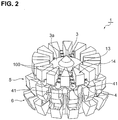
- Each radiation feeder 4 includes a trough 41 which extends outward toward the pool hopper 5 from the lower side of the outer edge of the conveying surface 3a and a screw 100 which is disposed in the trough 41.
- the screw 100 is rotated inside the trough 41 so that the article A fed into the trough 41 is conveyed toward the pool hopper 5.
- a guide block 14 is disposed between the adjacent radiation feeders 4 (see FIG. 2 ). The guide block 14 suppresses falling of the article A between the adjacent radiation feeders 4.
- Each pool hopper 5 is disposed below the front end portion of the trough 41 of each radiation feeder 4.
- Each pool hopper 5 includes a gate 5a which is able to be opened and closed with respect to the bottom portion thereof.
- Each pool hopper 5 temporarily stores the article A discharged from the front end portion of the corresponding trough 41 by closing the gate 5a. Further, each pool hopper 5 discharges the temporarily stored article A downward by opening the gate 5a.
- Each weighing hopper 6 is disposed below the gate 5a of each pool hopper 5.
- Each weighing hopper 6 includes a gate 6a and a gate 6b which are able to be opened and closed with respect to the bottom portion thereof.
- Each weighing hopper 6 temporarily stores the article A discharged from the corresponding pool hopper 5 by closing the gate 6a and the gate 6b. Further, each weighing hopper 6 discharges the temporarily stored article A downward by opening the gate 6a or the gate 6b.
- Each booster hopper 7 is disposed below the gate 6a of each weighing hopper 6.
- Each booster hopper 7 includes a gate 7a which is able to be opened and closed with respect to the bottom portion thereof.
- Each booster hopper 7 temporarily stores the article A discharged from the gate 6a of the corresponding weighing hopper 6 by closing the gate 7a. Further, each booster hopper 7 discharges the temporarily stored article A downward by opening the gate 7a.
- the collecting chute 8 has a cylindrical structure with a conical inner surface 8a which is narrowed downward.
- the collecting chute 8 is disposed so that the inner surface 8a is located below all weighing hoppers 6 and all booster hoppers 7.
- the collecting chute 8 receives the article A discharged from the gate 6b of each weighing hopper 6 and the article A discharged from each booster hopper 7 by the inner surface 8a and discharges the article A downward.
- the timing hopper 9 is disposed below the collecting chute 8.
- the timing hopper 9 includes a gate 9a which is able to be opened and closed with respect to the bottom portion thereof.
- the timing hopper 9 temporarily stores the article A discharged from the collecting chute 8 by closing the gate 9a. Further, the timing hopper 9 discharges the temporarily stored article A to the bag manufacturing and packaging machine 60 by opening the gate 9a.
- the weighing unit 11 is disposed inside a casing 13 supported by a frame 12.
- the weighing unit 11 includes a plurality of load cells 11a. Each load cell 11a supports the corresponding weighing hopper 6.
- the weighing unit 11 weighs the weighed value in response to the mass of the article A when the article A is temporarily stored in each weighing hopper 6.
- the control unit 20 is disposed inside the casing 13.
- the control unit 20 includes a central processing unit (CPU), a read only memory (ROM), a random access memory (RAM), and the like.
- the control unit 20 controls the operations of the components of the combination weighing device 1, such as the operations of the dispersion feeder 3 and the screw 100, the opening and closing operation of the gate 5a of each pool hopper 5, the opening and closing operations of the gate 6a and the gate 6b of each weighing hopper 6, the opening and closing operation of the gate 7a of each booster hopper 7, and the opening and closing operation of the gate 9a of each timing hopper 9. Additionally, the control unit 20 is connected to the bag manufacturing and packaging machine 60 to communicate with each other.
- the control unit 20 stores the weighed value weighed by the weighing unit 11 to correspond to at least one of the weighing hopper 6 and the booster hopper 7 storing the article A corresponding to the weighed value. Specifically, when the article A weighed by the weighing unit 11 is stored in the weighing hopper 6, the control unit 20 stores the weighed value weighed by the weighing unit 11 to correspond to the weighing hopper 6 storing the article A corresponding to the weighed value. When the article A weighed by the weighing unit 11 is discharged to the booster hopper 7 corresponding to the weighing hopper 6, the control unit 20 stores the weighed value of the article A weighed by the weighing unit 11 to correspond to the booster hopper 7 corresponding to the weighing hopper 6.
- the control unit 20 selects a combination of the weighed values from a plurality of weighed values weighed by the weighing unit 11 and corresponding to at least one of the plurality of weighing hoppers 6 and the plurality of booster hoppers 7 so that the total value becomes the target weighed value. Specifically, the control unit 20 selects a combination of the weighed values from the plurality of weighed values output from the weighing unit 11 so that the total value enters a predetermined range in which the target weighed value is a lower-limit value. Then, the control unit 20 causes at least one of the weighing hopper 6 and the booster hopper 7 corresponding to the combination to discharge the article A.
- the feeding chute 2, the dispersion feeder 3, the plurality of radiation feeders 4, the plurality of pool hoppers 5, and the plurality of weighing hoppers 6 are directly or indirectly supported by the casing 13.
- the plurality of booster hoppers 7, the collecting chute 8, and the timing hopper 9 are directly or indirectly supported by the frame 12.
- FIG. 2 shows a state where the feeding chute 2 shown in FIG. 1 is separated. Further, FIG. 2 only shows the upper portion of the weighing hopper 6.
- FIG. 3 shows a state where the guide block 14 shown in FIG. 2 is separated. Further, FIG. 3 shows a state where the screw 100 shown in FIG. 1 is separated except for one screw.
- FIG. 6 shows a state where the dispersion feeder 3 shown in FIG. 1 is separated.
- the plurality of radiation feeders 4 are attached to the side surface of the casing 13 to surround the periphery of the casing 13.
- Each radiation feeder 4 includes the trough 41 and the screw 100.
- the trough 41 is attached to the casing 13 and extends toward the pool hopper 5 disposed at the outside of the casing 13 (see FIG. 6 ).
- the article A is supplied to the weighing hopper 6 through the pool hopper 5 and is weighed by the weighing unit 11.
- the trough 41 constitutes a part of a conveying path for supplying the article A to the weighing unit 11. That is, the trough 41 extends toward the weighing unit 11 along the path of conveying the article A.
- the upper portion of the trough 41 is opened in the entire area of the portion provided with the screw 100 in the direction of conveying the article A.
- a bottom surface 41a (see FIG. 4 ) of the trough 41 is inclined downward toward the pool hopper 5. That is, as in gaps D1 and D2 shown in FIGS. 5A and 5B , a gap between the bottom surface 41a of the trough 41 and the screw 100 is widened toward the downstream side in the direction of conveying the article A.
- FIG. 5B is a cross-sectional view at the downstream position in the direction of conveying the article A in relation to FIG. 5A .
- the screw 100 is disposed inside the trough 41. As shown in FIG. 4 , the screw 100 includes a screw member 101, an end plate 102, and a screw shaft 103.
- the end plate 102 is a disc-shaped plate.
- the screw member 101 is attached to the downstream surface of the end plate 102 in the direction of conveying the article A by welding or the like.
- the screw shaft 103 is provided at the upstream surface of the end plate 102 in the direction of conveying the article A.
- the casing 13 accommodates a motor (a rotational driving unit) 105 and a drive shaft 104 rotated by the motor 105 for each radiation feeder 4.
- the drive shaft 104 includes a connection member 104a connected to the screw shaft 103 of the screw 100.
- the screw shaft 103 of the screw 100 is inserted into the casing 13 through a hole 13a provided in the casing 13 and is connected to the connection member 104a of the drive shaft 104. That is, the screw 100 is formed as a cantilever structure supported by an end portion connected to the drive shaft 104 (an upstream end portion in the direction of conveying the article A).
- the motor 105 rotates, the screw 100 rotates around the rotation axis C extending in the horizontal direction. Accordingly, the screw 100 conveys the article A fed into the trough 41 toward the pool hopper 5. Additionally, the rotation of the motor 105 is controlled by the control unit 20.
- the screw shaft 103 of the screw 100 is connected to the connection member 104a of the drive shaft 104 to be separable. For example, the screw 100 is separated when a cleaning operation is performed.
- the screw member 101 is a non-axial member that is formed as a spiral plate-shaped member extending in the direction of conveying the article A.
- the screw member 101 is rotated by the motor 105 to convey the article A toward the pool hopper 5.
- the motor 105 rotates the screw 100 in a direction in which the article A is conveyed to the pool hopper 5 by the screw member 101.
- the rotation axis C and the spiral axis of the screw member 101 are coaxial to each other.
- the screw member 101 of the embodiment has a space S extending in the direction of conveying the article A when viewed in the direction of conveying the article A. That is, the space S is formed around the rotation axis C of the screw member 101.
- the screw member 101 of the screw 100 is the non-axial member formed as the spiral plate-shaped member. Accordingly, the screw member 101 can decrease the space S formed around the spiral axis compared to a case where the screw member 101 is formed as a spiral rod when viewed in the spiral axis direction. For this reason, the screw 100 can suppress staying of the article A around the spiral axis of the screw member 101 and highly accurately convey a predetermined amount of the article A. Further, the screw 100 does not include a core or the like for suppressing the staying of the article A. For this reason, the screw 100 can be easily cleaned.
- the combination weighing device 1 can highly accurately convey a predetermined amount of the article A by the screw 100 and improve the cleaning performance of the screw 100.
- the screw member 101 of the screw 100 is non-axial, that is, does not have a shaft member other than the plate-shaped member. For this reason, a decrease in weight of the screw 100 can be realized.
- the screw 100 is formed as a cantilever structure supported by the upstream end portion (the screw shaft 103) in the direction of conveying the article A.
- the screw 100 can deliver the article A toward the pool hopper 5 from the downstream end portion in the conveying direction without causing the article A to stay at the downstream end portion in the conveying direction.
- a gap between the bottom surface 41a of the trough 41 and the screw 100 is widened toward the downstream side in the direction of conveying the article A.
- the screw 100 has a cantilever structure, a case is considered in which the screw 100 is bent so that the downstream end portion of the screw 100 in the direction of conveying the article A approaches the bottom surface 41a of the trough 41. Since a gap between the bottom surface 41a of the trough 41 and the screw 100 is widened toward the downstream side in the direction of conveying the article A, it is possible to suppress contacting of the screw 100 with the bottom surface 41a of the trough 41 even when the screw 100 is bent.
- the upper portion of the trough 41 is opened in the entire area of the portion provided with the screw 100 in the direction of conveying the article A.
- the screw 100 conveys a solid material (a semisolid material) such as meat as the article A.
- a screw 100A of the modified example includes a screw member 101A, an end plate 102, and a screw shaft 103.
- the screw member 101A is a non-axial member that is formed as a spiral plate-shaped member extending in the direction of conveying the article A.
- a space is not formed around the rotation axis C when viewed in the direction of conveying the article A (the rotation axis C of the screw 100A). That is, the screw member 101A has a shape in which the plate-shaped member is twisted around the rotation axis C.
- the screw 100A can suppress staying of the article A around the spiral axis of the screw member 101A and can highly accurately convey a predetermined amount of the article A.
- the plurality of hoppers may not be disposed in an annular shape as in the plurality of weighing hoppers 6 and the plurality of booster hoppers 7, but may be disposed in a matrix shape. Further, the combination weighing device of the present disclosure may not include the plurality of booster hoppers 7.
Landscapes
- Physics & Mathematics (AREA)
- General Physics & Mathematics (AREA)
- Weight Measurement For Supplying Or Discharging Of Specified Amounts Of Material (AREA)
Applications Claiming Priority (1)
| Application Number | Priority Date | Filing Date | Title |
|---|---|---|---|
| JP2017053423A JP2018155640A (ja) | 2017-03-17 | 2017-03-17 | 組合せ計量装置 |
Publications (2)
| Publication Number | Publication Date |
|---|---|
| EP3376185A1 true EP3376185A1 (fr) | 2018-09-19 |
| EP3376185B1 EP3376185B1 (fr) | 2020-11-18 |
Family
ID=61912939
Family Applications (1)
| Application Number | Title | Priority Date | Filing Date |
|---|---|---|---|
| EP18161405.8A Active EP3376185B1 (fr) | 2017-03-17 | 2018-03-13 | Dispositif de pesage par combinaison |
Country Status (3)
| Country | Link |
|---|---|
| EP (1) | EP3376185B1 (fr) |
| JP (1) | JP2018155640A (fr) |
| DK (1) | DK3376185T3 (fr) |
Citations (4)
| Publication number | Priority date | Publication date | Assignee | Title |
|---|---|---|---|---|
| EP1164365A1 (fr) * | 1999-12-24 | 2001-12-19 | Ishida Co., Ltd. | Dispositif de comptage et de pesage par lots |
| JP2008537099A (ja) | 2005-03-03 | 2008-09-11 | キャビンプラント・インターナショナル・アクティーゼルスカブ | 計量装置 |
| EP2116823A2 (fr) * | 2008-05-09 | 2009-11-11 | Ishida Co., Ltd. | Appareil de pesée par combinaison |
| DE202015101279U1 (de) * | 2015-01-20 | 2015-05-26 | Ishida Co., Ltd. | Kombinationswiegevorrichtung |
Family Cites Families (7)
| Publication number | Priority date | Publication date | Assignee | Title |
|---|---|---|---|---|
| US2765899A (en) | 1952-04-29 | 1956-10-09 | Wallace & Tiernan Inc | Dry feeder |
| GB1243595A (en) | 1969-06-17 | 1971-08-18 | Coal Industry Patents Ltd | Improvements in screw type feeders |
| DE2324202A1 (de) | 1973-05-12 | 1974-11-14 | Fritz E Knothe | Schneckenfoerderer |
| CN101654185A (zh) | 2008-08-21 | 2010-02-24 | 钱尧翎 | 一种无轴螺旋叶片 |
| WO2013085440A1 (fr) | 2011-12-08 | 2013-06-13 | Mixmo AB | Dispositif distributeur |
| WO2015160681A1 (fr) | 2014-04-15 | 2015-10-22 | Stanley Black & Decker, Inc. | Vis sans fin et manchon |
| JP2016061690A (ja) | 2014-09-18 | 2016-04-25 | 株式会社イシダ | 組合せ計量装置 |
-
2017
- 2017-03-17 JP JP2017053423A patent/JP2018155640A/ja active Pending
-
2018
- 2018-03-13 DK DK18161405.8T patent/DK3376185T3/da active
- 2018-03-13 EP EP18161405.8A patent/EP3376185B1/fr active Active
Patent Citations (4)
| Publication number | Priority date | Publication date | Assignee | Title |
|---|---|---|---|---|
| EP1164365A1 (fr) * | 1999-12-24 | 2001-12-19 | Ishida Co., Ltd. | Dispositif de comptage et de pesage par lots |
| JP2008537099A (ja) | 2005-03-03 | 2008-09-11 | キャビンプラント・インターナショナル・アクティーゼルスカブ | 計量装置 |
| EP2116823A2 (fr) * | 2008-05-09 | 2009-11-11 | Ishida Co., Ltd. | Appareil de pesée par combinaison |
| DE202015101279U1 (de) * | 2015-01-20 | 2015-05-26 | Ishida Co., Ltd. | Kombinationswiegevorrichtung |
Also Published As
| Publication number | Publication date |
|---|---|
| JP2018155640A (ja) | 2018-10-04 |
| DK3376185T3 (da) | 2020-11-30 |
| EP3376185B1 (fr) | 2020-11-18 |
Similar Documents
| Publication | Publication Date | Title |
|---|---|---|
| US10801880B2 (en) | Combination weighing device with hoppers and discharge chutes having complementary surfaces | |
| US11333546B2 (en) | Combination weighing apparatus with improved hopper attachment workability | |
| EP3620759B1 (fr) | Dispositif de pesage | |
| EP3598085B1 (fr) | Dispositif de pesage combiné | |
| EP3564632B1 (fr) | Dispositif de pesage combiné | |
| EP3875923B1 (fr) | Corps de support et dispositif de retenue d'articles | |
| JPWO2017119257A1 (ja) | 組合せ計量装置 | |
| US10794755B2 (en) | Combination weighing device with discharge chutes having receiving and sliding surfaces of varying widths | |
| EP3376185B1 (fr) | Dispositif de pesage par combinaison | |
| EP3546898B1 (fr) | Appareil de transport et appareil de pesée combiné | |
| JPS62175625A (ja) | 物品供給装置 | |
| CN112478267B (zh) | 定时料斗及组合计量装置 | |
| JP2018155638A (ja) | 組合せ計量装置 | |
| US11274959B2 (en) | Weighing apparatus and combination weighing apparatus | |
| KR101141747B1 (ko) | 사료 정량 공급장치 | |
| JP2018155636A (ja) | 分散装置及び組合せ計量装置 | |
| JP2018048837A (ja) | 組合せ計量装置 |
Legal Events
| Date | Code | Title | Description |
|---|---|---|---|
| PUAI | Public reference made under article 153(3) epc to a published international application that has entered the european phase |
Free format text: ORIGINAL CODE: 0009012 |
|
| STAA | Information on the status of an ep patent application or granted ep patent |
Free format text: STATUS: THE APPLICATION HAS BEEN PUBLISHED |
|
| AK | Designated contracting states |
Kind code of ref document: A1 Designated state(s): AL AT BE BG CH CY CZ DE DK EE ES FI FR GB GR HR HU IE IS IT LI LT LU LV MC MK MT NL NO PL PT RO RS SE SI SK SM TR |
|
| AX | Request for extension of the european patent |
Extension state: BA ME |
|
| STAA | Information on the status of an ep patent application or granted ep patent |
Free format text: STATUS: REQUEST FOR EXAMINATION WAS MADE |
|
| 17P | Request for examination filed |
Effective date: 20190319 |
|
| RBV | Designated contracting states (corrected) |
Designated state(s): AL AT BE BG CH CY CZ DE DK EE ES FI FR GB GR HR HU IE IS IT LI LT LU LV MC MK MT NL NO PL PT RO RS SE SI SK SM TR |
|
| GRAP | Despatch of communication of intention to grant a patent |
Free format text: ORIGINAL CODE: EPIDOSNIGR1 |
|
| STAA | Information on the status of an ep patent application or granted ep patent |
Free format text: STATUS: GRANT OF PATENT IS INTENDED |
|
| RIC1 | Information provided on ipc code assigned before grant |
Ipc: G01G 19/393 20060101AFI20200518BHEP |
|
| INTG | Intention to grant announced |
Effective date: 20200615 |
|
| GRAS | Grant fee paid |
Free format text: ORIGINAL CODE: EPIDOSNIGR3 |
|
| GRAA | (expected) grant |
Free format text: ORIGINAL CODE: 0009210 |
|
| STAA | Information on the status of an ep patent application or granted ep patent |
Free format text: STATUS: THE PATENT HAS BEEN GRANTED |
|
| AK | Designated contracting states |
Kind code of ref document: B1 Designated state(s): AL AT BE BG CH CY CZ DE DK EE ES FI FR GB GR HR HU IE IS IT LI LT LU LV MC MK MT NL NO PL PT RO RS SE SI SK SM TR |
|
| REG | Reference to a national code |
Ref country code: GB Ref legal event code: FG4D |
|
| REG | Reference to a national code |
Ref country code: DK Ref legal event code: T3 Effective date: 20201124 Ref country code: CH Ref legal event code: EP |
|
| REG | Reference to a national code |
Ref country code: IE Ref legal event code: FG4D |
|
| REG | Reference to a national code |
Ref country code: DE Ref legal event code: R096 Ref document number: 602018009724 Country of ref document: DE |
|
| REG | Reference to a national code |
Ref country code: AT Ref legal event code: REF Ref document number: 1336273 Country of ref document: AT Kind code of ref document: T Effective date: 20201215 |
|
| REG | Reference to a national code |
Ref country code: AT Ref legal event code: MK05 Ref document number: 1336273 Country of ref document: AT Kind code of ref document: T Effective date: 20201118 |
|
| REG | Reference to a national code |
Ref country code: NL Ref legal event code: MP Effective date: 20201118 |
|
| PG25 | Lapsed in a contracting state [announced via postgrant information from national office to epo] |
Ref country code: RS Free format text: LAPSE BECAUSE OF FAILURE TO SUBMIT A TRANSLATION OF THE DESCRIPTION OR TO PAY THE FEE WITHIN THE PRESCRIBED TIME-LIMIT Effective date: 20201118 Ref country code: PT Free format text: LAPSE BECAUSE OF FAILURE TO SUBMIT A TRANSLATION OF THE DESCRIPTION OR TO PAY THE FEE WITHIN THE PRESCRIBED TIME-LIMIT Effective date: 20210318 Ref country code: FI Free format text: LAPSE BECAUSE OF FAILURE TO SUBMIT A TRANSLATION OF THE DESCRIPTION OR TO PAY THE FEE WITHIN THE PRESCRIBED TIME-LIMIT Effective date: 20201118 Ref country code: NO Free format text: LAPSE BECAUSE OF FAILURE TO SUBMIT A TRANSLATION OF THE DESCRIPTION OR TO PAY THE FEE WITHIN THE PRESCRIBED TIME-LIMIT Effective date: 20210218 Ref country code: GR Free format text: LAPSE BECAUSE OF FAILURE TO SUBMIT A TRANSLATION OF THE DESCRIPTION OR TO PAY THE FEE WITHIN THE PRESCRIBED TIME-LIMIT Effective date: 20210219 |
|
| PG25 | Lapsed in a contracting state [announced via postgrant information from national office to epo] |
Ref country code: AT Free format text: LAPSE BECAUSE OF FAILURE TO SUBMIT A TRANSLATION OF THE DESCRIPTION OR TO PAY THE FEE WITHIN THE PRESCRIBED TIME-LIMIT Effective date: 20201118 Ref country code: BG Free format text: LAPSE BECAUSE OF FAILURE TO SUBMIT A TRANSLATION OF THE DESCRIPTION OR TO PAY THE FEE WITHIN THE PRESCRIBED TIME-LIMIT Effective date: 20210218 Ref country code: LV Free format text: LAPSE BECAUSE OF FAILURE TO SUBMIT A TRANSLATION OF THE DESCRIPTION OR TO PAY THE FEE WITHIN THE PRESCRIBED TIME-LIMIT Effective date: 20201118 Ref country code: IS Free format text: LAPSE BECAUSE OF FAILURE TO SUBMIT A TRANSLATION OF THE DESCRIPTION OR TO PAY THE FEE WITHIN THE PRESCRIBED TIME-LIMIT Effective date: 20210318 Ref country code: PL Free format text: LAPSE BECAUSE OF FAILURE TO SUBMIT A TRANSLATION OF THE DESCRIPTION OR TO PAY THE FEE WITHIN THE PRESCRIBED TIME-LIMIT Effective date: 20201118 Ref country code: SE Free format text: LAPSE BECAUSE OF FAILURE TO SUBMIT A TRANSLATION OF THE DESCRIPTION OR TO PAY THE FEE WITHIN THE PRESCRIBED TIME-LIMIT Effective date: 20201118 |
|
| REG | Reference to a national code |
Ref country code: LT Ref legal event code: MG9D |
|
| PG25 | Lapsed in a contracting state [announced via postgrant information from national office to epo] |
Ref country code: HR Free format text: LAPSE BECAUSE OF FAILURE TO SUBMIT A TRANSLATION OF THE DESCRIPTION OR TO PAY THE FEE WITHIN THE PRESCRIBED TIME-LIMIT Effective date: 20201118 |
|
| PG25 | Lapsed in a contracting state [announced via postgrant information from national office to epo] |
Ref country code: SK Free format text: LAPSE BECAUSE OF FAILURE TO SUBMIT A TRANSLATION OF THE DESCRIPTION OR TO PAY THE FEE WITHIN THE PRESCRIBED TIME-LIMIT Effective date: 20201118 Ref country code: RO Free format text: LAPSE BECAUSE OF FAILURE TO SUBMIT A TRANSLATION OF THE DESCRIPTION OR TO PAY THE FEE WITHIN THE PRESCRIBED TIME-LIMIT Effective date: 20201118 Ref country code: SM Free format text: LAPSE BECAUSE OF FAILURE TO SUBMIT A TRANSLATION OF THE DESCRIPTION OR TO PAY THE FEE WITHIN THE PRESCRIBED TIME-LIMIT Effective date: 20201118 Ref country code: EE Free format text: LAPSE BECAUSE OF FAILURE TO SUBMIT A TRANSLATION OF THE DESCRIPTION OR TO PAY THE FEE WITHIN THE PRESCRIBED TIME-LIMIT Effective date: 20201118 Ref country code: CZ Free format text: LAPSE BECAUSE OF FAILURE TO SUBMIT A TRANSLATION OF THE DESCRIPTION OR TO PAY THE FEE WITHIN THE PRESCRIBED TIME-LIMIT Effective date: 20201118 Ref country code: LT Free format text: LAPSE BECAUSE OF FAILURE TO SUBMIT A TRANSLATION OF THE DESCRIPTION OR TO PAY THE FEE WITHIN THE PRESCRIBED TIME-LIMIT Effective date: 20201118 |
|
| REG | Reference to a national code |
Ref country code: DE Ref legal event code: R026 Ref document number: 602018009724 Country of ref document: DE |
|
| PLBI | Opposition filed |
Free format text: ORIGINAL CODE: 0009260 |
|
| PLAX | Notice of opposition and request to file observation + time limit sent |
Free format text: ORIGINAL CODE: EPIDOSNOBS2 |
|
| 26 | Opposition filed |
Opponent name: MAREL A/S Effective date: 20210818 |
|
| PG25 | Lapsed in a contracting state [announced via postgrant information from national office to epo] |
Ref country code: AL Free format text: LAPSE BECAUSE OF FAILURE TO SUBMIT A TRANSLATION OF THE DESCRIPTION OR TO PAY THE FEE WITHIN THE PRESCRIBED TIME-LIMIT Effective date: 20201118 Ref country code: NL Free format text: LAPSE BECAUSE OF FAILURE TO SUBMIT A TRANSLATION OF THE DESCRIPTION OR TO PAY THE FEE WITHIN THE PRESCRIBED TIME-LIMIT Effective date: 20201118 Ref country code: MC Free format text: LAPSE BECAUSE OF FAILURE TO SUBMIT A TRANSLATION OF THE DESCRIPTION OR TO PAY THE FEE WITHIN THE PRESCRIBED TIME-LIMIT Effective date: 20201118 Ref country code: IT Free format text: LAPSE BECAUSE OF FAILURE TO SUBMIT A TRANSLATION OF THE DESCRIPTION OR TO PAY THE FEE WITHIN THE PRESCRIBED TIME-LIMIT Effective date: 20201118 |
|
| REG | Reference to a national code |
Ref country code: CH Ref legal event code: PL |
|
| PG25 | Lapsed in a contracting state [announced via postgrant information from national office to epo] |
Ref country code: SI Free format text: LAPSE BECAUSE OF FAILURE TO SUBMIT A TRANSLATION OF THE DESCRIPTION OR TO PAY THE FEE WITHIN THE PRESCRIBED TIME-LIMIT Effective date: 20201118 |
|
| REG | Reference to a national code |
Ref country code: BE Ref legal event code: MM Effective date: 20210331 |
|
| PLBB | Reply of patent proprietor to notice(s) of opposition received |
Free format text: ORIGINAL CODE: EPIDOSNOBS3 |
|
| PG25 | Lapsed in a contracting state [announced via postgrant information from national office to epo] |
Ref country code: FR Free format text: LAPSE BECAUSE OF NON-PAYMENT OF DUE FEES Effective date: 20210331 Ref country code: ES Free format text: LAPSE BECAUSE OF FAILURE TO SUBMIT A TRANSLATION OF THE DESCRIPTION OR TO PAY THE FEE WITHIN THE PRESCRIBED TIME-LIMIT Effective date: 20201118 Ref country code: CH Free format text: LAPSE BECAUSE OF NON-PAYMENT OF DUE FEES Effective date: 20210331 Ref country code: LI Free format text: LAPSE BECAUSE OF NON-PAYMENT OF DUE FEES Effective date: 20210331 Ref country code: LU Free format text: LAPSE BECAUSE OF NON-PAYMENT OF DUE FEES Effective date: 20210313 Ref country code: IE Free format text: LAPSE BECAUSE OF NON-PAYMENT OF DUE FEES Effective date: 20210313 |
|
| PG25 | Lapsed in a contracting state [announced via postgrant information from national office to epo] |
Ref country code: IS Free format text: LAPSE BECAUSE OF FAILURE TO SUBMIT A TRANSLATION OF THE DESCRIPTION OR TO PAY THE FEE WITHIN THE PRESCRIBED TIME-LIMIT Effective date: 20210318 |
|
| PG25 | Lapsed in a contracting state [announced via postgrant information from national office to epo] |
Ref country code: BE Free format text: LAPSE BECAUSE OF NON-PAYMENT OF DUE FEES Effective date: 20210331 |
|
| PLCK | Communication despatched that opposition was rejected |
Free format text: ORIGINAL CODE: EPIDOSNREJ1 |
|
| PG25 | Lapsed in a contracting state [announced via postgrant information from national office to epo] |
Ref country code: CY Free format text: LAPSE BECAUSE OF FAILURE TO SUBMIT A TRANSLATION OF THE DESCRIPTION OR TO PAY THE FEE WITHIN THE PRESCRIBED TIME-LIMIT Effective date: 20201118 |
|
| APBM | Appeal reference recorded |
Free format text: ORIGINAL CODE: EPIDOSNREFNO |
|
| APBP | Date of receipt of notice of appeal recorded |
Free format text: ORIGINAL CODE: EPIDOSNNOA2O |
|
| APAH | Appeal reference modified |
Free format text: ORIGINAL CODE: EPIDOSCREFNO |
|
| PG25 | Lapsed in a contracting state [announced via postgrant information from national office to epo] |
Ref country code: HU Free format text: LAPSE BECAUSE OF FAILURE TO SUBMIT A TRANSLATION OF THE DESCRIPTION OR TO PAY THE FEE WITHIN THE PRESCRIBED TIME-LIMIT; INVALID AB INITIO Effective date: 20180313 |
|
| APAL | Date of receipt of statement of grounds of an appeal modified |
Free format text: ORIGINAL CODE: EPIDOSCNOA3O |
|
| APBQ | Date of receipt of statement of grounds of appeal recorded |
Free format text: ORIGINAL CODE: EPIDOSNNOA3O |
|
| PG25 | Lapsed in a contracting state [announced via postgrant information from national office to epo] |
Ref country code: MK Free format text: LAPSE BECAUSE OF FAILURE TO SUBMIT A TRANSLATION OF THE DESCRIPTION OR TO PAY THE FEE WITHIN THE PRESCRIBED TIME-LIMIT Effective date: 20201118 |
|
| APAH | Appeal reference modified |
Free format text: ORIGINAL CODE: EPIDOSCREFNO |
|
| PG25 | Lapsed in a contracting state [announced via postgrant information from national office to epo] |
Ref country code: MT Free format text: LAPSE BECAUSE OF FAILURE TO SUBMIT A TRANSLATION OF THE DESCRIPTION OR TO PAY THE FEE WITHIN THE PRESCRIBED TIME-LIMIT Effective date: 20201118 |
|
| PG25 | Lapsed in a contracting state [announced via postgrant information from national office to epo] |
Ref country code: TR Free format text: LAPSE BECAUSE OF FAILURE TO SUBMIT A TRANSLATION OF THE DESCRIPTION OR TO PAY THE FEE WITHIN THE PRESCRIBED TIME-LIMIT Effective date: 20201118 |
|
| APBU | Appeal procedure closed |
Free format text: ORIGINAL CODE: EPIDOSNNOA9O |
|
| PGFP | Annual fee paid to national office [announced via postgrant information from national office to epo] |
Ref country code: GB Payment date: 20260324 Year of fee payment: 9 |
|
| PGFP | Annual fee paid to national office [announced via postgrant information from national office to epo] |
Ref country code: DE Payment date: 20260320 Year of fee payment: 9 Ref country code: DK Payment date: 20260323 Year of fee payment: 9 |