EP3376200A1 - Vorrichtung zur diagnose von anomalien - Google Patents
Vorrichtung zur diagnose von anomalien Download PDFInfo
- Publication number
- EP3376200A1 EP3376200A1 EP16864285.8A EP16864285A EP3376200A1 EP 3376200 A1 EP3376200 A1 EP 3376200A1 EP 16864285 A EP16864285 A EP 16864285A EP 3376200 A1 EP3376200 A1 EP 3376200A1
- Authority
- EP
- European Patent Office
- Prior art keywords
- heat flux
- sensor
- heat
- flux sensor
- abnormality
- Prior art date
- Legal status (The legal status is an assumption and is not a legal conclusion. Google has not performed a legal analysis and makes no representation as to the accuracy of the status listed.)
- Ceased
Links
Images


Classifications
-
- G—PHYSICS
- G01—MEASURING; TESTING
- G01M—TESTING STATIC OR DYNAMIC BALANCE OF MACHINES OR STRUCTURES; TESTING OF STRUCTURES OR APPARATUS, NOT OTHERWISE PROVIDED FOR
- G01M99/00—Subject matter not provided for in other groups of this subclass
- G01M99/002—Thermal testing
-
- G—PHYSICS
- G01—MEASURING; TESTING
- G01K—MEASURING TEMPERATURE; MEASURING QUANTITY OF HEAT; THERMALLY-SENSITIVE ELEMENTS NOT OTHERWISE PROVIDED FOR
- G01K17/00—Measuring quantity of heat
- G01K17/06—Measuring quantity of heat conveyed by flowing media, e.g. in heating systems e.g. the quantity of heat in a transporting medium, delivered to or consumed in an expenditure device
- G01K17/08—Measuring quantity of heat conveyed by flowing media, e.g. in heating systems e.g. the quantity of heat in a transporting medium, delivered to or consumed in an expenditure device based upon measurement of temperature difference or of a temperature
- G01K17/20—Measuring quantity of heat conveyed by flowing media, e.g. in heating systems e.g. the quantity of heat in a transporting medium, delivered to or consumed in an expenditure device based upon measurement of temperature difference or of a temperature across a radiating surface, combined with ascertainment of the heat-transmission coefficient
-
- G—PHYSICS
- G01—MEASURING; TESTING
- G01M—TESTING STATIC OR DYNAMIC BALANCE OF MACHINES OR STRUCTURES; TESTING OF STRUCTURES OR APPARATUS, NOT OTHERWISE PROVIDED FOR
- G01M13/00—Testing of machine parts
-
- G—PHYSICS
- G01—MEASURING; TESTING
- G01M—TESTING STATIC OR DYNAMIC BALANCE OF MACHINES OR STRUCTURES; TESTING OF STRUCTURES OR APPARATUS, NOT OTHERWISE PROVIDED FOR
- G01M13/00—Testing of machine parts
- G01M13/02—Gearings; Transmission mechanisms
Definitions
- the present invention relates to an abnormality diagnosis apparatus for diagnosing the presence or absence of an abnormality in a target apparatus.
- the present inventors have studied an abnormality diagnosis apparatus which makes a diagnosis regarding an abnormality of a target apparatus which is a diagnostic target using a heat flux sensor, and have found the following problems.
- a target apparatus such as a productive facility
- an operating state and a resting state are repeated. While the target apparatus is operating, heat is generated at the target apparatus by friction, vibration, or the like. While the target apparatus is in a resting state, heat generation at the target apparatus is stopped. Therefore, if an operating state and a resting state of the target apparatus are repeated, a waveform of a heat flux generated from the target apparatus becomes a waveform in which increase and decrease are repeated over time. If the target apparatus operates normally, the heat flux generated from the target apparatus changes within a predetermined range. On the other hand, if an abnormality occurs at the target apparatus, the heat flux generated from the target apparatus falls outside the predetermined range.
- the abnormality diagnosis apparatus includes a heat flux sensor and a determining unit.
- the heat flux sensor detects the hear flux generated from the target apparatus.
- the determining unit determines whether or not a detection value of the heat flux sensor falls within the predetermined range. According to this abnormality diagnosis apparatus, it is possible to diagnose a state of the target apparatus as abnormal when the detection value falls outside the predetermined range.
- the heat flux detected by the heat flux sensor changes by being affected by the environmental temperature. Therefore, in a case where a conventional heat flux sensor is used, there is a possibility that the detection value may fall outside the predetermined range even if the state of the target apparatus is normal, and the abnormality diagnosis apparatus may erroneously diagnose the state of the target apparatus as abnormal. Further, if a wide predetermined range is set in view of influence of the environmental temperature, there is a possibility that the state may be erroneously diagnosed as normal even if the state of the target apparatus is abnormal.
- an object of the present invention is to provide an abnormality diagnosis apparatus capable of making a diagnosis regarding an abnormality of a target apparatus with high accuracy.
- a first aspect according to an abnormality diagnosis apparatus is an abnormality diagnosis apparatus which makes a diagnosis regarding an abnormality of a target apparatus, the apparatus includes a sensor unit provided at the target apparatus and configured to detect a heat flux which flows outward from the target apparatus, and a determining unit configured to detect an abnormality of the target apparatus, the sensor unit including a first heat flux sensor, a second heat flux sensor disposed on a side farther from the target apparatus than the first heat flux sensor is, and a thermal buffer disposed between the first heat flux sensor and the second heat flux sensor and having a predetermined heat capacity, the first heat flux sensor outputting a first sensor signal in accordance with a heat flux which passes through the first heat flux sensor from the target apparatus side toward the thermal buffer side, the second heat flux sensor outputting a second sensor signal in accordance with a heat flux which passes through the second heat flux sensor from the thermal buffer side toward an opposite side to the thermal buffer side, and the determining unit determining whether or not there is an abnormality of the target apparatus on the basis of the first sensor signal and the second sensor
- the thermal buffer is disposed between the first heat flux sensor and the second heat flux sensor. Therefore, when the heat flux emitted from the target apparatus changes, the heat flux which passes through the second heat flux sensor moderately changes later than the change of the heat flux which passes through the first heat flux sensor. It is therefore possible to detect the change of the heat flux emitted from the target apparatus from a difference between the first sensor signal and the second sensor signal.
- the first heat flux sensor and the second heat flux sensor are disposed on both sides of the thermal buffer, and disposed at positions relatively close to each other. Further, change of the environmental temperature which is a temperature in an environment in which the sensor unit is provided normally occurs moderately over a long period of time. Therefore, the first heat flux sensor and the second heat flux sensor are affected by the environmental temperature in the same way or in almost exactly the same way.
- the first heat flux sensor and the second heat flux sensor respectively output sensor signals in accordance with the heat fluxes which are affected by the environmental temperatures which are the same or which are almost exactly the same. It is therefore possible to eliminate or reduce influence by the environmental temperature on the detection result of the sensor unit by using the both sensor signals.
- the abnormality diagnosis apparatus of the present invention it is possible to make a diagnosis regarding an abnormality of a target apparatus with high accuracy.
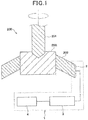
- an abnormality diagnosis apparatus 1 of the present embodiment uses an automatic cutting machine 200 as a target apparatus for abnormality diagnosis.
- the automatic cutting machine 200 includes a drill 201 and a chuck portion 202.
- the drill 201 is a cutting tool to be used for cutting work.
- the chuck portion 202 is a holding apparatus which holds a workpiece 203 which is to be processed.
- the automatic cutting machine 200 sequentially processes a plurality of workpieces 203 by repeating a processing state and a resting state. During processing, heat is generated at a portion where the drill 201 contacts with the workpiece 203. Therefore, a heat current flows from the portion where the drill 201 contacts with the workpiece 203 to the chuck portion 202. The heat current flows from the chuck portion 202 to outside.
- the abnormality diagnosis apparatus 1 includes a sensor unit 2, a control apparatus 3 and a display apparatus 4.
- the sensor unit 2 detects a heat flux directed from the chuck portion 202 to outside.
- the sensor unit 2 outputs a sensor signal in accordance with the heat flux directed from the chuck portion 202 to outside to the control apparatus 3.
- the sensor unit 2 is attached on a surface of the chuck portion 202. A structure of the sensor unit 2 will be described in detail later.
- the sensor unit 2 is connected to an input side of the control apparatus 3.
- the control apparatus 3 performs abnormality diagnosis control of the automatic cutting machine 200.
- This abnormality diagnosis control is a control for determining whether or not there is an abnormality at the automatic cutting machine 200 on the basis of a detection result of the sensor unit 2. Therefore, the control apparatus 3 constitutes a determining unit which determines whether or not there is an abnormality at the target apparatus on the basis of a detection result of the heat flux sensor 10.
- An abnormality of the automatic cutting machine 200 is a breakage of the drill 201, for example.
- a display apparatus 4 is connected to an output side of the control apparatus 3.
- the control apparatus 3 causes the display apparatus 4 to display that there is an abnormality when there is an abnormality.
- the control apparatus 3 is configured to include a microcomputer, a storage apparatus, or the like.
- the display apparatus 4 is an informing apparatus for informing a user that there is an abnormality.
- a liquid crystal display, or the like are used as the display apparatus 4.
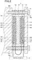
- the sensor unit 2 includes two heat flux sensors 10, a thermal buffer 11 and a heat sink 12.
- the two heat flux sensors 10, the thermal buffer 11 and the heat sink 12 are all formed in a flat plate shape.
- One of the two heat flux sensors 10 is a first heat flux sensor 10a.
- Another one of the two heat flux sensors 10 is a second heat flux sensor 10b.
- the first heat flux sensor 10a is disposed in contact with an outer surface of the chuck portion 202.
- the second heat flux sensor 10b is disposed on a side farther from the chuck portion 202 than the first heat flux sensor 10a.
- the thermal buffer 11 is disposed between the first heat flux sensor 10a and the second heat flux sensor 10b.
- the heat sink 12 is disposed on a side farther from the chuck portion 202 than the second heat flux sensor 10b. That is, in the sensor unit 2, the first heat flux sensor 10a, the thermal buffer 11, the second heat flux sensor 10b and the heat sink 12 are sequentially disposed from a side closer to the chuck portion 202 to a side farther from the chuck portion 202.
- the first heat flux sensor 10a outputs a first sensor signal in accordance with a heat flux which passes through the first heat flux sensor 10a from the chuck portion 202 side to the thermal buffer 11 side of the first heat flux sensor 10a.
- the second heat flux sensor 10b outputs a second sensor signal in accordance with a heat flux which passes through the second heat flux sensor 10b from the thermal buffer 11 side to a side opposite to the thermal buffer 11 side of the second heat flux sensor 10b.
- the first heat flux sensor 10a and the second heat flux sensor 10b have rectangular shapes of the same shape and the same size.
- the thermal buffer 11 has predetermined heat capacity.
- the thermal buffer 11 is formed of a metal material or a resin material.
- a material and a thickness of the thermal buffer 11 are set so as to achieve a heat capacity which enables change of the heat flux emitted from the chuck portion 202 toward outside to be detected as will be described later.
- a shape and a size of the planar shape of the thermal buffer 11 are the same as the shape and the size of the planar shape of the first heat flux sensor 10a. Note that the shape and the size of the planar shape of the thermal buffer 11 may be different from the shape and the size of the planar shape of the first heat flux sensor 10a.
- the heat sink 12 has predetermined heat capacity.
- the heat sink 12 is formed of a metal material or a resin material. A material and a thickness of the heat sink 12 are set so that the heat capacity becomes larger than the heat capacity of the thermal buffer 11.
- a planar shape of the heat sink 12 is larger than the planar shapes of the first heat flux sensor 10a, the thermal buffer 11 and the second heat flux sensor 10b.
- the heat sink 12 is fixed at the chuck portion 202 with the first heat flux sensor 10a, the thermal buffer 11 and the second heat flux sensor 10b being sandwiched between the heat sink 12 and the chuck portion 202.
- screw holes are formed at an outer peripheral portion of the heat sink 12.
- the heat sink 12 is fixed at the chuck portion 202 with screws 13 inserted into the screw holes. Note that spacers 14 are disposed between the chuck portion 202 and the heat sink 12. The screw 13 penetrates inside the spacer 14.
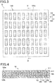
- one heat flux sensor 10 has a structure in which an insulating substrate 100, a surface protective member 110 and a back surface protective member 120 are integrated, inside of which first and second thermoelectric members 130 and 140 are alternately connected in series.
- the surface protective member 110 is omitted.
- the insulating substrate 100, the surface protective member 110 and the back surface protective member 120 have a film shape and are formed of a resin material such as a thermoplastic resin having flexibility.
- On the insulating substrate 100 a plurality of first and second via holes 101 and 102 which penetrate in the thickness direction thereof are formed.
- a connection portion of one of the first and the second thermoelectric members 130 and 140 is formed by a surface conductive pattern 111 disposed on a surface 100a of the insulating substrate 100.
- a connection portion of another one of the first and the second thermoelectric members 130 and 140 is formed by a back surface conductive pattern 121 disposed on a back surface 100b of the insulating substrate 100.
- thermoelectric force occurs at the first and the second thermoelectric members 130 and 140 by the Seebeck effect.
- the heat flux sensor 10 outputs this thermoelectric force, specifically, a voltage as the sensor signal.
- the first heat flux sensor 10a and the second heat flux sensor 10b are configured to output sensor signals of which absolute values are the same when the heat fluxes passing through the first heat flux sensor 10a and the second heat flux sensor 10b have the same magnitude.
- the first heat flux sensor 10a and the second heat flux sensor 10b are electrically connected to the control apparatus 3 in a state where the first heat flux sensor 10a and the second heat flux sensor 10b are connected to each other in series.
- the first heat flux sensor 10a and the second heat flux sensor 10b are arranged so as to output the first sensor signal and the second sensor signal of which polarities are inverse when the heat flux from the chuck portion 202 sequentially passes through the first heat flux sensor 10a and the second heat flux sensor 10b.
- the first and the second heat flux sensors 10a and 10b are arranged so that the surface protective members 110 of the first and the second heat flux sensors 10a and 10b face each other. Further, although not illustrated, the surface conductive patterns 111 of the first and the second heat flux sensors 10a and 10b are connected to each other via an external wiring 151. Each of the back surface conductive patterns 121 of the first and the second heat flux sensors 10a and 10b is connected to the control apparatus 3 via an external wiring 152.
- the first and the second heat flux sensors 10a and 10b output positive sensor signals when a heat flux passes from the back surface protective member 120 side to the surface protective member 110 side. Therefore, if a heat flux flows from the chuck portion 202 side toward the heat sink 12 side, a positive sensor signal is outputted from the first heat flux sensor 10a, and a negative sensor signal is outputted from the second heat flux sensor 10b.
- the sensor unit 2 outputs a sensor signal in which the first sensor signal and the second sensor signal are combined to the control apparatus 3.
- the sensor signal output from the sensor unit 2 becomes large.
- a case where a heat flux emitted from a target rapidly increases corresponds to such a case.
- a difference between the heat fluxes which pass through the first and the second heat flux sensors 10a and 10b is small, output from the sensor unit 2 becomes small.
- a case where a heat flux emitted from the target decreases or a case where predetermined time has elapsed while a constant heat flux is emitted from the target corresponds to such a case.
- the automatic cutting machine 200 When processing of one workpiece 203 is finished, the automatic cutting machine 200 stands by in a resting state until preparation for processing of the next workpiece 203 is completed. The automatic cutting machine 200 starts processing the next workpiece 203 when preparation for processing of the next workpiece 203 is completed. In this manner, the automatic cutting machine 200 repeats an operating cycle including a processing state and a resting state in one cycle.
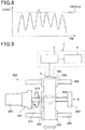
- a waveform indicating change of the output value of the sensor unit 2 over time becomes a waveform which regularly increases/decreases along the operating cycle of the automatic cutting machine 200.
- the reason is as described below.
- a heat flux which flows through the chuck portion 202 increases.
- the heat flux which flows through the chuck portion 202 decreases when the processing is finished.
- the first heat flux sensor 10a has nothing for blocking the heat flux from the chuck portion 202. Therefore, the heat flux which passes through the first heat flux sensor 10a increases/decreases in a similar manner to the heat flux which flows through the chuck portion 202.
- the thermal buffer 11 is disposed on the first heat flux sensor 10a side. The thermal buffer 11 performs heat accumulation and heat transfer. Therefore, the heat flux does not pass through the second heat flux sensor 10b.
- a heat flux which passes through the second heat flux sensor 10b moderately increases/decreases later than increase/decrease of the heat flux which passes through the first heat flux sensor 10a.
- the sensor signal output from the sensor unit 2 toward the control apparatus 3 is a combined signal of the first sensor signal and the second sensor signal. Therefore, the output value of the sensor unit 2 regularly increases/decreases along the operating cycle of the automatic cutting machine 200.
- a sudden abnormality for example, breakage occurs at the bit of the drill 201 during processing
- abnormal heat generation occurs by the workpiece 203 being rubbed against the drill 201. Therefore, as illustrated in Fig. 6 , when a sudden abnormality occurs at the bit of the drill 201, the output value rises and becomes larger than that in a normal state. Accordingly, a threshold for distinguishing between a normal state and a state where a sudden abnormality occurs is set in advance, and the output value of the sensor unit 2 is compared with the threshold. By this means, it is possible to determine whether or not there is a sudden abnormality.
- the control apparatus 3 makes a diagnosis regarding an abnormality on the basis of the detection result of the sensor unit 2.
- respective steps illustrated in Fig. 7 constitute a function implementing unit which implements various kinds of functions.
- control apparatus 3 acquires the detection value of the sensor unit 2 in step S1.
- the control apparatus 3 acquires an output value (specifically, a voltage value) of the sensor unit 2 at predetermined time. Note that it is also possible to acquire a correction value obtained by correcting the output value as the detection value instead of using the output value of the sensor unit 2 as is.
- the control apparatus 3 determines whether or not there is an abnormality by comparing the detection value with the threshold in step S2.
- the detection value does not exceed the threshold, asat time T1 illustrated in Fig. 6 .
- it is determined that there is no abnormality In the case where it is determined that there is no abnormality, the control apparatus 3 performs step S1 again.
- the control apparatus 3 determines that there is an abnormality.
- control apparatus 3 In the case where it is determined that there is an abnormality, the control apparatus 3 outputs a control signal for causing the display apparatus 4 to display that there is an abnormality in step S3.
- a maintenance worker is informed of the abnormality.
- the maintenance worker can take necessary measures, that is, can replace the drill 201.
- the abnormality diagnosis apparatus 1 of the present embodiment includes the sensor unit 2 which detects a heat flux flowing from the chuck portion 202 toward outside, and the control apparatus 3 which determines an abnormality of the drill 201.
- the heat flux flowing from the chuck portion 202 is generated by heat generation at a portion where the drill 201 contacts with the workpiece 203.
- the thermal buffer 11 is disposed between the first heat flux sensor 10a and the second heat flux sensor 10b. The thermal buffer 11 performs heat accumulation and heat transfer. Therefore, when the heat flux emitted from the chuck portion 202 changes, the heat flux which passes through the second heat flux sensor 10b moderately changes later than change of the heat flux which passes through the first heat flux sensor 10a. Therefore, it is possible to detect change of the heat flux emitted from the chuck portion 202 from a difference between the first sensor signal and the second sensor signal.
- the heat flux which passes through the heat flux sensor 10 also changes by being affected by the environmental temperature. That is, even if an amount of heat generation at the portion where the drill 201 contacts with the workpiece 203 does not change, the heat flux which passes through the heat flux sensor 10 increases if the environmental temperature decreases.
- Fig. 8 there is a case where, even if the bit of the drill 201 is in a normal state, the output value of the sensor unit 2 exceeds the threshold by fluctuation of the environmental temperature of one day.
- the control apparatus 3 erroneously determines a state of the bit of the drill 201 as abnormal. Further, to avoid this erroneous determination, there is a possible way in which the threshold is set higher in view of fluctuation of the environmental temperature.
- the threshold is set higher in view of fluctuation of the environmental temperature.
- the first heat flux sensor 10a and the second heat flux sensor 10b of the sensor unit 2 of the present embodiment are disposed on the both sides of the thermal buffer 11. Therefore, the both are disposed at positions relatively close to each other. Further, the environmental temperature around the sensor unit 2 normally changes moderately over a long period of time of one day. Therefore, even if the thermal buffer 11 is disposed between the first heat flux sensor 10a and the second heat flux sensor 10b, the first heat flux sensor 10a and the second heat flux sensor 10b are affected by the environmental temperature in the same way or in almost the same way.
- the first heat flux sensor 10a and the second heat flux sensor 10b respectively output sensor signals in accordance with the heat fluxes affected by the same environmental temperature.
- an output waveform of the sensor unit 2 when the bit of the drill 201 is in a normal state becomes a waveform in which influence of the environmental temperature is eliminated as illustrated in Fig. 5 .
- the abnormality diagnosis apparatus 1 of the present embodiment it is possible to make a diagnosis regarding an abnormality of the automatic cutting machine 200 with high accuracy.
- absolute values of outputs with respect to the same magnitude of the heat fluxes does not have to be always the same. It is only necessary that absolute values of the both outputs are close to each other. Also in this case, it is possible to reduce influence of the environmental temperature on the detection result of the sensor unit 2 by using a sum of the outputs of the first heat flux sensor 10a and the second heat flux sensor 10b.
- the first heat flux sensor 10a and the second heat flux sensor 10b output the first sensor signal and the second sensor signal of which polarities are opposite with respect to each other when the heat flux from the chuck portion 202 sequentially passes through the first heat flux sensor 10a and the second heat flux sensor 10b.
- the first heat flux sensor 10a and the second heat flux sensor 10b are electrically connected to the control apparatus 3 in a state where the first heat flux sensor 10a and the second heat flux sensor 10b are connected to each other in series.
- the sensor unit 2 may employ a configuration not including the heat sink 12.
- a surface temperature of the second heat flux sensor 10b instantaneously changes due to wind blowing against the surface of the second heat flux sensor 10b, or the like. This affects the heat flux which passes through the sensor unit 2. Therefore, detection accuracy of the heat flux of the sensor unit 2 degrades.
- the sensor unit 2 of the present embodiment includes the heat sink 12 having predetermined heat capacity.
- the heat capacity of the heat sink 12 is larger than the heat capacity of the thermal buffer 11.
- an abnormality diagnosis apparatus 1 of the present invention uses a workpiece feeding apparatus 300 as a target apparatus for abnormality diagnosis.
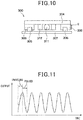
- the workpiece feeding apparatus 300 includes a ball screw 301, a supporting member 302, a motor 303, a seat 304, rails 305 and guide blocks 306. Note that, in Fig. 10 , the supporting member 302 is omitted to facilitate understanding.
- the ball screw 301 is a mechanical element part which converts rotation movement into linear movement.
- the ball screw 301 includes a screw shaft 311, a nut 312 and balls 313.
- the balls 313 are inserted between the screw shaft 311 and the nut 312. If the screw shaft 311 rotates, the nut 312 linearly moves.
- the supporting member 302 supports both end portions of the screw shaft 311 in a shaft direction.
- the motor 303 is a power source which rotates the screw shaft 311.
- the seat 304 is provided so that an apparatus which is desired to be transferred, or the like, is mounted.
- the seat 304 is made a planar rectangular shape in which a direction orthogonal to the shaft direction of the screw shaft 311 (that is, a vertical direction in Fig. 9 ) is made a longitudinal direction.
- An approximately center portion of the seat 304 in the longitudinal direction is connected to the nut 312.
- Both end portions of the seat 304 in the longitudinal direction are connected to the guide blocks 306.
- the rails 305 are linear members. Two rails 305 are used, and, as illustrated in Fig, 10 , the rails 305 are fixed at a base plate 307.
- the guide blocks 306 are engaged with the rails 305.
- the guide blocks 306 are guide members which move along the rails 305.
- the guide blocks 306 slide with respect to the rails 305.
- a configuration of the abnormality diagnosis apparatus 1 of the present embodiment is the same as that of the abnormality diagnosis apparatus 1 of the first embodiment.
- the sensor unit 2 is attached on a surface of the guide block 306 of the workpiece feeding apparatus 300. While illustration is omitted, in the sensor unit 2, the first heat flux sensor 10a, the thermal buffer 11, the second heat flux sensor 10b and the heat sink 12 are sequentially disposed from a side closer to the guide block 306 toward a side farther from the guide block 306.
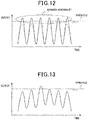
- the workpiece feeding apparatus 300 repeats an operating cycle including a traveling state and a resting state of the seat 304 as one cycle. While the seat 304 is traveling, the output value of the sensor unit 2 increases by friction of a sliding portion of the guide block 306. While the seat 304 is in a resting state, the output value of the sensor unit 2 decreases.
- a waveform indicating change of the output value of the sensor unit 2 over time becomes a waveform which regularly increases and decreases along the operating cycle of the workpiece feeding apparatus 300.
- the control apparatus 3 makes a diagnosis regarding an abnormality on the basis of the detection result of the sensor unit 2. Specifically, the control apparatus 3 compares the detection value of the sensor unit 2 with the threshold. As indicated with an undulating line in Fig. 12 , in a case where the detection value does not exceed the threshold, the control apparatus 3 determines that there is no abnormality. Meanwhile, as indicated with a solid line in Fig. 12 , in a case where the detection value exceeds the threshold, the control apparatus 3 determines that there is an abnormality. In this manner, according to the abnormality diagnosis apparatus 1 of the present embodiment, it is possible to make a diagnosis regarding whether or not there is an abnormality over time at the workpiece feeding apparatus 300.
- the heat flux which passes through the heat flux sensor 10 also changes by being affected by the environmental temperature. That is, even if an amount of heat generation at the sliding portion of the guide block 306 does not change, the heat flux which passes through the heat flux sensor 10 increases if the environmental temperature decreases.
- the control apparatus 3 erroneously determines a state of the guide block 306 as abnormal. Further, to avoid this erroneous determination, it is also possible to set the threshold higher in view of the fluctuation of the environmental temperature. However, in this case, even if the state of the guide block 306 is abnormal, it is erroneously determined that the state of the guide block 306 is normal. That is, sensitivity of detection of an abnormality at the guide block 306 is lowered.
- the sensor unit 2 of the present embodiment it is possible to eliminate influence of the environmental temperature on the detection result of the sensor unit 2 by using a sum of output of the first heat flux sensor 10a and output of the second heat flux sensor 10b.
- an output waveform of the sensor unit 2 when the sliding portion of the guide block 306 is in a normal state becomes a waveform in which influence of the environmental temperature is eliminated as illustrated in Fig. 10 .
- the abnormality diagnosis apparatus 1 of the present embodiment it is possible to make a diagnosis regarding an abnormality of the workpiece feeding apparatus 300 with high accuracy.
- the present embodiment is an embodiment in which the configuration of the sensor unit 2 is changed from that in the first embodiment.
- the other configuration of the abnormality diagnosis apparatus 1 is the same as that of the first embodiment.
- the sensor unit 2 of the present embodiment includes a flat plate heat receiver 16.
- the heat receiver 16 is disposed closer to the chuck portion 202 than the first heat flux sensor 10a. That is, the heat receiver 16 is disposed between the chuck portion 202 and the first heat flux sensor 10a.
- the heat receiver 16 has predetermined heat capacity in a similar manner to the thermal buffer 11 and the heat sink 12.
- the heat receiver 16 is formed of a metal material or a resin material. A material and a thickness of the heat receiver 16 are set so that the heat capacity becomes smaller than those of the thermal buffer 11 and the heat sink 12.
- a shape and a size of the planar shape of the heat receiver 16 are the same as the shape and the size of the planar shape of the first heat flux sensor 10a. Note that the shape and the size of the planar shape of the heat receiver 16 may be different from the shape and the size of the planar shape of the first heat flux sensor 10a.
- heat capacity of the heat receiver 16 is set small. Therefore, the sensor unit 2 of the present embodiment can detect change of the heat flux by operation and rest of the drill 201 which is a detection target. That is, in the sensor unit 2 of the present embodiment, the heat capacity of the heat receiver 16 is set so as to be able to detect change of the heat flux by operation and rest of the drill 201.
- the abnormality diagnosis apparatus 1 of the present embodiment can make a diagnosis regarding an abnormality of the automatic cutting machine 200 with high accuracy.
- the sensor unit 2 may be configured to include the heat receiver 16.
- the present embodiment is an embodiment in which the configuration of the sensor unit 2 is changed from that in the first embodiment.
- the other configuration of the abnormality diagnosis apparatus 1 is the same as that of the first embodiment.
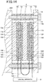
- the first and the second heat flux sensors 10a and 10b are connected via a bent-shaped portion 10c having a bent shape.
- the bent-shaped portion 10c has a structure in which an insulating substrate 100, a surface protective member 110 and a back surface protective member 120 are laminated in a similar manner to the first and the second heat flux sensors 10a and 10b. In this manner, in the sensor unit 2 of the present embodiment, the first and the second heat flux sensors 10a and 10b are integrated.
- the sensor unit 2 of the present embodiment has a structure in which one heat flux sensor 10 is bent so as to sandwich the thermal buffer 11.
- each of the insulating substrate 100, the surface protective member 110 and the back surface protective member 120 in the heat flux sensor 10 is formed of a resin material having flexibility. Therefore, it is possible to easily bend the heat flux sensor 10. By this means, it is possible to realize a configuration in which the thermal buffer 11 is disposed between the first heat flux sensor 10a and the second heat flux sensor 10b.
- the first heat flux sensor 10a is electrically connected to the second heat flux sensor 10b by wiring patterns inside the heat flux sensor 10 instead of by the external wiring 151. Note that the first heat flux sensor 10a may be connected to the second heat flux sensor 10b through respective surface conductive patterns 111.
- the first and the second heat flux sensors 10a and 10b are configured as one heat flux sensor 10, so that it is possible to eliminate the external wiring 151 for connecting the first heat flux sensor 10a and the second heat flux sensor 10b. It is therefore possible to realize reduction in the number of parts.
- an abnormality diagnosis apparatus includes a sensor unit and a determining unit.
- the sensor unit includes a first heat flux sensor, a second heat flux sensor, and a thermal buffer disposed between the first heat flux sensor and the second heat flux sensor.
- the first heat flux sensor outputs a first sensor signal in accordance with a heat flux which passes through the first heat flux sensor.
- the second heat flux sensor outputs a second sensor signal in accordance with a heat flux which passes through the second heat flux sensor.
- the determining unit determines whether or not there is an abnormality of a target apparatus on the basis of the first sensor signal and the second sensor signal.
- the sensor unit includes a heat sink which is disposed on a side farther from the target apparatus than the second heat flux sensor, and which has predetermined heat capacity.
- the heat capacity of the heat sink is larger than heat capacity of the thermal buffer. According to this, it is possible to make heat flow from the target apparatus toward the heat sink even when a large amount of heat is emitted from the target apparatus. Therefore, it is possible to prevent heat from being confined inside the sensor unit.
- the sensor unit includes a heat receiver which is disposed closer to the target apparatus than the first heat flux sensor.
- the heat capacity of the heat receiver is smaller than the heat capacity of the thermal buffer.
- the first heat flux sensor and the second heat flux sensor are arranged so that polarities of the first sensor signal and the second sensor signal become opposite with respect to each other when a heat flux from the target apparatus sequentially passes through the first heat flux sensor and the second heat flux sensor.
- the first heat flux sensor and the second heat flux sensor are electrically connected in series.
- the sensor unit can output a sensor signal which is a combined signal of the first sensor signal and the second sensor signal. It is therefore possible to eliminate necessity of processing of calculating a sum of the first sensor signal and the second sensor signal.
- each of the first heat flux sensor and the second heat flux sensor includes a film-like insulating substrate having flexibility, a plurality of first thermoelectric members and a plurality of second thermoelectric members.
- the plurality of first thermoelectric members and the plurality of second thermoelectric members are connected such that the first thermoelectric members and the second thermoelectric members are alternately connected in series.
- the first heat flux sensor is connected to the second heat flux sensor via a bent-shaped portion including an insulating material.
Landscapes
- Physics & Mathematics (AREA)
- General Physics & Mathematics (AREA)
- Chemical & Material Sciences (AREA)
- Engineering & Computer Science (AREA)
- Combustion & Propulsion (AREA)
- Measuring Temperature Or Quantity Of Heat (AREA)
- Testing Of Devices, Machine Parts, Or Other Structures Thereof (AREA)
Priority Applications (1)
| Application Number | Priority Date | Filing Date | Title |
|---|---|---|---|
| EP20168775.3A EP3699567A1 (de) | 2015-11-12 | 2016-11-10 | Abnormalitätsdiagnose-gerät |
Applications Claiming Priority (2)
| Application Number | Priority Date | Filing Date | Title |
|---|---|---|---|
| JP2015222446A JP6249009B2 (ja) | 2015-11-12 | 2015-11-12 | 異常診断装置 |
| PCT/JP2016/083305 WO2017082324A1 (ja) | 2015-11-12 | 2016-11-10 | 異常診断装置 |
Related Child Applications (1)
| Application Number | Title | Priority Date | Filing Date |
|---|---|---|---|
| EP20168775.3A Division EP3699567A1 (de) | 2015-11-12 | 2016-11-10 | Abnormalitätsdiagnose-gerät |
Publications (3)
| Publication Number | Publication Date |
|---|---|
| EP3376200A1 true EP3376200A1 (de) | 2018-09-19 |
| EP3376200A4 EP3376200A4 (de) | 2018-11-14 |
| EP3376200A8 EP3376200A8 (de) | 2019-01-23 |
Family
ID=58695429
Family Applications (2)
| Application Number | Title | Priority Date | Filing Date |
|---|---|---|---|
| EP16864285.8A Ceased EP3376200A4 (de) | 2015-11-12 | 2016-11-10 | Vorrichtung zur diagnose von anomalien |
| EP20168775.3A Withdrawn EP3699567A1 (de) | 2015-11-12 | 2016-11-10 | Abnormalitätsdiagnose-gerät |
Family Applications After (1)
| Application Number | Title | Priority Date | Filing Date |
|---|---|---|---|
| EP20168775.3A Withdrawn EP3699567A1 (de) | 2015-11-12 | 2016-11-10 | Abnormalitätsdiagnose-gerät |
Country Status (7)
| Country | Link |
|---|---|
| US (1) | US10788379B2 (de) |
| EP (2) | EP3376200A4 (de) |
| JP (1) | JP6249009B2 (de) |
| KR (1) | KR102059644B1 (de) |
| CN (1) | CN108351277B (de) |
| TW (1) | TWI619935B (de) |
| WO (1) | WO2017082324A1 (de) |
Families Citing this family (6)
| Publication number | Priority date | Publication date | Assignee | Title |
|---|---|---|---|---|
| JP6358233B2 (ja) | 2015-11-12 | 2018-07-18 | 株式会社デンソー | 組付状態の診断装置 |
| JP6358234B2 (ja) | 2015-11-12 | 2018-07-18 | 株式会社デンソー | 稼働状態の診断装置 |
| JP6988468B2 (ja) * | 2017-12-27 | 2022-01-05 | 株式会社デンソー | 締結部材一体型歪み検出装置およびそれを用いた診断装置 |
| JP6988469B2 (ja) * | 2017-12-27 | 2022-01-05 | 株式会社デンソー | 歪み検出装置およびそれを用いた診断装置 |
| US11527987B2 (en) * | 2018-12-27 | 2022-12-13 | Mitsubishi Electric Corporation | Abnormality diagnosis device and abnormality diagnosis method |
| CN115237177B (zh) * | 2022-08-03 | 2023-03-14 | 中国科学技术大学 | 一种基于主被动复合一体的宽频段温度噪声抑制方法 |
Family Cites Families (25)
| Publication number | Priority date | Publication date | Assignee | Title |
|---|---|---|---|---|
| JPS5376086A (en) | 1976-12-17 | 1978-07-06 | Glory Kogyo Kk | Machine for counting paper web and like |
| US4779994A (en) | 1987-10-15 | 1988-10-25 | Virginia Polytechnic Institute And State University | Heat flux gage |
| JPH03213249A (ja) * | 1990-01-16 | 1991-09-18 | Omron Corp | 熱流計測を利用した工具のモニタリング方法 |
| JPH05301144A (ja) | 1992-04-23 | 1993-11-16 | Suzuki Motor Corp | 工作機械の暖機装置 |
| JPH07229865A (ja) * | 1994-02-22 | 1995-08-29 | Hitachi Ltd | 管内付着物の検出装置 |
| JP2001165782A (ja) * | 1999-12-10 | 2001-06-22 | Mitsubishi Heavy Ind Ltd | 熱流束測定ゲージ |
| ES2561829T3 (es) * | 2002-10-15 | 2016-03-01 | Danfoss A/S | Un procedimiento para detectar una anomalía de un intercambiador de calor |
| DE102006016956B4 (de) * | 2006-04-11 | 2009-10-08 | Electrolux Home Products Corp. N.V. | Verfahren zum Bestimmen der von einem Gargut aufgenommenen Wärme in einem Gargerät und Gargerät zur Durchführung des Verfahrens |
| JP2008057670A (ja) * | 2006-08-31 | 2008-03-13 | F C C:Kk | クラッチの発熱量推定装置 |
| US7368827B2 (en) * | 2006-09-06 | 2008-05-06 | Siemens Power Generation, Inc. | Electrical assembly for monitoring conditions in a combustion turbine operating environment |
| DE102006061794B3 (de) * | 2006-12-21 | 2008-04-30 | Thermosensorik Gmbh | Verfahren zur automatischen Prüfung einer Schweißverbindung |
| CN101678582B (zh) * | 2007-05-31 | 2013-06-19 | 住友重机械工业株式会社 | 注射成形机的显示装置 |
| US8606554B2 (en) * | 2009-10-19 | 2013-12-10 | Siemens Aktiengesellschaft | Heat flow model for building fault detection and diagnosis |
| CN102879419B (zh) * | 2011-07-15 | 2014-04-09 | 郭晓明 | 一种建筑保温材料的监控系统 |
| JP2014007376A (ja) * | 2012-05-30 | 2014-01-16 | Denso Corp | 熱電変換装置 |
| JP5376086B1 (ja) | 2012-05-30 | 2013-12-25 | 株式会社デンソー | 熱電変換装置の製造方法、熱電変換装置を備える電子部品の製造方法 |
| JP5662381B2 (ja) * | 2012-06-15 | 2015-01-28 | 日立オートモティブシステムズ株式会社 | 熱式流量計 |
| JP5761302B2 (ja) * | 2013-06-04 | 2015-08-12 | 株式会社デンソー | 車両用の快適温調制御装置 |
| JP5942960B2 (ja) | 2013-06-04 | 2016-06-29 | 株式会社デンソー | 発熱量制御装置 |
| US9350319B2 (en) * | 2014-02-24 | 2016-05-24 | Siemens Energy, Inc. | Self-powered sensing and transmitting device and method of fabricating the same |
| JP6225766B2 (ja) * | 2014-03-13 | 2017-11-08 | オムロン株式会社 | 内部温度測定方法及び内部温度測定装置 |
| JP6303973B2 (ja) * | 2014-10-20 | 2018-04-04 | 株式会社デンソー | 状態検出センサ |
| FR3028314B1 (fr) * | 2014-11-07 | 2016-12-23 | Aircelle Sa | Procede de caracterisation du vieillissement thermique de materiaux composites, en particulier de materiaux composites a matrice organique |
| JP6358233B2 (ja) * | 2015-11-12 | 2018-07-18 | 株式会社デンソー | 組付状態の診断装置 |
| JP6763142B2 (ja) * | 2015-12-28 | 2020-09-30 | セイコーエプソン株式会社 | 内部温度測定装置、リスト装着型装置及び内部温度測定方法 |
-
2015
- 2015-11-12 JP JP2015222446A patent/JP6249009B2/ja active Active
-
2016
- 2016-11-10 US US15/775,761 patent/US10788379B2/en active Active
- 2016-11-10 WO PCT/JP2016/083305 patent/WO2017082324A1/ja not_active Ceased
- 2016-11-10 EP EP16864285.8A patent/EP3376200A4/de not_active Ceased
- 2016-11-10 KR KR1020187013555A patent/KR102059644B1/ko not_active Expired - Fee Related
- 2016-11-10 CN CN201680065807.0A patent/CN108351277B/zh not_active Expired - Fee Related
- 2016-11-10 EP EP20168775.3A patent/EP3699567A1/de not_active Withdrawn
- 2016-11-11 TW TW105136937A patent/TWI619935B/zh not_active IP Right Cessation
Also Published As
| Publication number | Publication date |
|---|---|
| TWI619935B (zh) | 2018-04-01 |
| KR20180066221A (ko) | 2018-06-18 |
| KR102059644B1 (ko) | 2019-12-26 |
| EP3376200A8 (de) | 2019-01-23 |
| JP2017090320A (ja) | 2017-05-25 |
| EP3699567A1 (de) | 2020-08-26 |
| EP3376200A4 (de) | 2018-11-14 |
| CN108351277A (zh) | 2018-07-31 |
| WO2017082324A1 (ja) | 2017-05-18 |
| US20180372560A1 (en) | 2018-12-27 |
| JP6249009B2 (ja) | 2017-12-20 |
| US10788379B2 (en) | 2020-09-29 |
| TW201728889A (zh) | 2017-08-16 |
| CN108351277B (zh) | 2021-03-23 |
Similar Documents
| Publication | Publication Date | Title |
|---|---|---|
| US10788379B2 (en) | Abnormality diagnosis apparatus | |
| KR102131855B1 (ko) | 조립 상태의 진단 장치 | |
| JP2017090318A5 (de) | ||
| KR102134003B1 (ko) | 가동 상태의 진단 장치 | |
| JP2017015521A (ja) | 吸湿剤の吸湿量を取得する機能を備えた回転エンコーダ | |
| US11131340B2 (en) | Linear guideway with embedded sensor | |
| JP2019168396A (ja) | ボールねじ装置の異常検出装置 | |
| JP2017090319A5 (de) | ||
| JP2019117154A (ja) | 歪み検出装置およびそれを用いた診断装置 | |
| EP3467524B1 (de) | Sensorschnittstellen, sensoranordnungen und leerlauferkennungsverfahren für sensorschnittstellen und anordnungen | |
| WO2017010309A1 (ja) | 加速度検出装置 | |
| KR20150104777A (ko) | 다이오드를 이용한 회로 상의 임계 온도 측정 장치 및 이를 포함하는 전장품 제어 시스템 | |
| JP2013186721A (ja) | 電源回路とそれを用いた電子制御装置 |
Legal Events
| Date | Code | Title | Description |
|---|---|---|---|
| PUAI | Public reference made under article 153(3) epc to a published international application that has entered the european phase |
Free format text: ORIGINAL CODE: 0009012 |
|
| 17P | Request for examination filed |
Effective date: 20180605 |
|
| AK | Designated contracting states |
Kind code of ref document: A1 Designated state(s): AL AT BE BG CH CY CZ DE DK EE ES FI FR GB GR HR HU IE IS IT LI LT LU LV MC MK MT NL NO PL PT RO RS SE SI SK SM TR |
|
| AX | Request for extension of the european patent |
Extension state: BA ME |
|
| RAP1 | Party data changed (applicant data changed or rights of an application transferred) |
Owner name: DENSO CORPORATION |
|
| A4 | Supplementary search report drawn up and despatched |
Effective date: 20181015 |
|
| RIC1 | Information provided on ipc code assigned before grant |
Ipc: G01M 13/02 20060101ALI20181009BHEP Ipc: G01K 3/08 20060101ALI20181009BHEP Ipc: G01M 99/00 20110101AFI20181009BHEP Ipc: G01K 17/20 20060101ALI20181009BHEP |
|
| 17Q | First examination report despatched |
Effective date: 20181026 |
|
| DAV | Request for validation of the european patent (deleted) | ||
| DAX | Request for extension of the european patent (deleted) | ||
| REG | Reference to a national code |
Ref country code: DE Ref legal event code: R003 |
|
| STAA | Information on the status of an ep patent application or granted ep patent |
Free format text: STATUS: THE APPLICATION HAS BEEN REFUSED |
|
| 18R | Application refused |
Effective date: 20191217 |