EP3376333B1 - Pedalvorrichtung und herstellungsverfahren dafür - Google Patents
Pedalvorrichtung und herstellungsverfahren dafür Download PDFInfo
- Publication number
- EP3376333B1 EP3376333B1 EP18160080.0A EP18160080A EP3376333B1 EP 3376333 B1 EP3376333 B1 EP 3376333B1 EP 18160080 A EP18160080 A EP 18160080A EP 3376333 B1 EP3376333 B1 EP 3376333B1
- Authority
- EP
- European Patent Office
- Prior art keywords
- pedal
- board
- housing
- hall sensor
- terminals
- Prior art date
- Legal status (The legal status is an assumption and is not a legal conclusion. Google has not performed a legal analysis and makes no representation as to the accuracy of the status listed.)
- Active
Links
Images


Classifications
-
- B—PERFORMING OPERATIONS; TRANSPORTING
- B60—VEHICLES IN GENERAL
- B60K—ARRANGEMENT OR MOUNTING OF PROPULSION UNITS OR OF TRANSMISSIONS IN VEHICLES; ARRANGEMENT OR MOUNTING OF PLURAL DIVERSE PRIME-MOVERS IN VEHICLES; AUXILIARY DRIVES FOR VEHICLES; INSTRUMENTATION OR DASHBOARDS FOR VEHICLES; ARRANGEMENTS IN CONNECTION WITH COOLING, AIR INTAKE, GAS EXHAUST OR FUEL SUPPLY OF PROPULSION UNITS IN VEHICLES
- B60K26/00—Arrangement or mounting of propulsion-unit control devices in vehicles
- B60K26/02—Arrangement or mounting of propulsion-unit control devices in vehicles of initiating means or elements
-
- G—PHYSICS
- G05—CONTROLLING; REGULATING
- G05G—CONTROL DEVICES OR SYSTEMS INSOFAR AS CHARACTERISED BY MECHANICAL FEATURES ONLY
- G05G1/00—Controlling members, e.g. knobs or handles; Assemblies or arrangements thereof; Indicating position of controlling members
- G05G1/30—Controlling members actuated by foot
- G05G1/38—Controlling members actuated by foot comprising means to continuously detect pedal position
-
- G—PHYSICS
- G05—CONTROLLING; REGULATING
- G05G—CONTROL DEVICES OR SYSTEMS INSOFAR AS CHARACTERISED BY MECHANICAL FEATURES ONLY
- G05G1/00—Controlling members, e.g. knobs or handles; Assemblies or arrangements thereof; Indicating position of controlling members
- G05G1/30—Controlling members actuated by foot
- G05G1/32—Controlling members actuated by foot with means to prevent injury
-
- G—PHYSICS
- G05—CONTROLLING; REGULATING
- G05G—CONTROL DEVICES OR SYSTEMS INSOFAR AS CHARACTERISED BY MECHANICAL FEATURES ONLY
- G05G1/00—Controlling members, e.g. knobs or handles; Assemblies or arrangements thereof; Indicating position of controlling members
- G05G1/30—Controlling members actuated by foot
- G05G1/44—Controlling members actuated by foot pivoting
-
- G—PHYSICS
- G05—CONTROLLING; REGULATING
- G05G—CONTROL DEVICES OR SYSTEMS INSOFAR AS CHARACTERISED BY MECHANICAL FEATURES ONLY
- G05G1/00—Controlling members, e.g. knobs or handles; Assemblies or arrangements thereof; Indicating position of controlling members
- G05G1/30—Controlling members actuated by foot
- G05G1/46—Means, e.g. links, for connecting the pedal to the controlled unit
-
- G—PHYSICS
- G05—CONTROLLING; REGULATING
- G05G—CONTROL DEVICES OR SYSTEMS INSOFAR AS CHARACTERISED BY MECHANICAL FEATURES ONLY
- G05G1/00—Controlling members, e.g. knobs or handles; Assemblies or arrangements thereof; Indicating position of controlling members
- G05G1/30—Controlling members actuated by foot
- G05G1/50—Manufacturing of pedals; Pedals characterised by the material used
- G05G1/506—Controlling members for foot-actuation
-
- G—PHYSICS
- G05—CONTROLLING; REGULATING
- G05G—CONTROL DEVICES OR SYSTEMS INSOFAR AS CHARACTERISED BY MECHANICAL FEATURES ONLY
- G05G5/00—Means for preventing, limiting or returning the movements of parts of a control mechanism, e.g. locking controlling member
- G05G5/05—Means for returning or tending to return controlling members to an inoperative or neutral position, e.g. by providing return springs or resilient end-stops
-
- G—PHYSICS
- G05—CONTROLLING; REGULATING
- G05G—CONTROL DEVICES OR SYSTEMS INSOFAR AS CHARACTERISED BY MECHANICAL FEATURES ONLY
- G05G2505/00—Means for preventing, limiting or returning the movements of parts of a control mechanism, e.g. locking controlling member
Definitions
- One or more example embodiments relate to a pedal apparatus and a manufacturing method thereof.
- a pedal apparatus is installed in a vehicle, and types thereof include an accelerator pedal apparatus and a brake pedal apparatus.
- types thereof include an accelerator pedal apparatus and a brake pedal apparatus.
- ETS electronic throttle system
- the ETS electronically controls an acceleration of a vehicle.
- a general ETS includes an accelerator pedal position sensor (APS) mounted on an accelerator pedal to transmit a press state and position information of the accelerator pedal to an electric control unit (ECU).
- APS accelerator pedal position sensor
- ECU electric control unit
- the ECU calculates an amount of air to flow in an engine based on the press state and the position information of the accelerator pedal, and transmits an opening angle of a throttle valve to an electric throttle controller (ETC) based on a corresponding result to control a speed of the vehicle based on an acceleration requested by a driver.
- ETC electric throttle controller
- a prior art vehicle accelerator pedal apparatus (on which the preamble of claim 1 is based) is disclosed in patent JP 2007-276707 A .
- the apparatus includes a hollow housing with a cover and accommodating a part of a pedal arm which is journaled for rotation by engagement with inner surfaces of the housing and the cover.
- the pedal arm rotates around a hollow shaft which extends through the cover, the pedal arm and the housing and in which a circuit board including a Hall sensor is positioned which senses movement of a magnet embedded in the pedal arm.
- An aspect provides a pedal apparatus including a sensor configured to sense a position of a pedal pad using a magnetic field in a contactless manner.
- the Hall sensor may be positioned on the rotation axis.
- the pedal cover may further include a connector fastener to which a connector electrically connected to the sensing board to transmit a signal sensed by the Hall sensor to an outside is fastened.
- the pedal apparatus may further include a plurality of terminals to be electrically connected to the connector, the plurality of terminals positioned in the connector fastener and installed in a direction perpendicular to the sensing board.
- the connector fastener and the cover body may be formed as an integral body.
- the sensing board may include a board main part on which the Hall sensor is installed, and a board end part including a terminal fastening hole through which the plurality of terminals are fastened thereto.
- a width of the board end part may be greater than a width of the board main part such that the sensing board may not be inserted into the board insertion space in excess of a predetermined length.
- the pedal cover may further include a support rib formed on an inner surface of the board insertion space, the support rib configured to prevent the board end part from moving backward when the plurality of terminals are fastened to the board end part.
- the pedal cover may further include a cover lid configured to shield the board insertion space from the outside.
- the sensing board Before the cover lid is installed, the sensing board may be inserted and installed through the board insertion space in a direction parallel to the rotation axis.
- the plurality of terminals When the sensing board is installed, the plurality of terminals may be inserted in a direction perpendicular to the rotation axis and fastened to the sensing board through the connector fastener.
- the pedal apparatus may further include a connecting link configured to connect the pedal pad and one end of the pedal arm, a pressurizing member with one end supported by a lower side of the one end of the pedal arm, and another end provided between an upper inner surface of the pedal housing and the rotation axis, and an elastic member disposed between a middle part of the pressurizing member and a lower inner surface of the pedal housing.
- the pedal apparatus may further include a pressurizing member with one end supported by an upper side of one end of the pedal arm, and another end provided between a lower inner surface of the pedal housing and the rotation axis, and an elastic member disposed between a middle part of the pressurizing member and an upper inner surface of the pedal housing.
- the magnet may include a pair of magnets positioned on opposite side from the Hall sensor, and facing surfaces of the pair of magnets may have opposite magnetisms or polarities.
- a method of manufacturing a pedal apparatus including a pedal pad, a pedal housing, a pedal arm installed in an inner space of the pedal housing, the pedal arm configured to rotate in response to an operation of the pedal pad, and a pedal cover configured to shield the inner space of the pedal housing, the method including inserting a sensing board including a Hall sensor from an outside in a direction perpendicular to a surface of the pedal cover such that the Hall sensor may be positioned in a hollow of the pedal arm, and inserting a plurality of terminals configured to transmit a signal sensed by the Hall sensor to the outside in a direction perpendicular to the sensing board such that the plurality of terminals may be installed on the sensing board.
- the plurality of terminals may be installed on the sensing board using press fit.
- the pedal cover may include a connector fastener to which a connector electrically connected to the sensing board to transmit the signal sensed by the Hall sensor to the outside is fastened, and the plurality of terminals may be inserted through the connector fastener and installed on the sensing board.
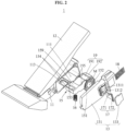
- FIG. 1 is a perspective view illustrating a pedal apparatus according to an example embodiment
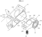
- FIG. 2 is an exploded perspective view illustrating the pedal apparatus according to an example embodiment
- FIG. 3 illustrates a relation between a sensing board and a magnet according to an example embodiment.
- FIG. 4 is an exploded perspective view illustrating a connection between a pedal arm and a pedal housing according to an example embodiment
- FIG. 5 is an exploded perspective view illustrating a connection between the pedal arm and a pedal cover according to an example embodiment.
- FIG. 6 is an exploded perspective view illustrating a connection between the pedal arm and a pressurizing member according to an example embodiment
- FIG. 7 illustrates the pressurizing member rotating with respect to the pedal arm according to an example embodiment
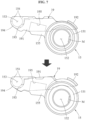
- FIGS. 8 and 9 are cross-sectional views illustrating an operation of the pedal apparatus according to an example embodiment.
- a pedal apparatus 1 may be installed in a conveyance such as a vehicle.
- the pedal apparatus 1 may sense how far a user presses a pedal pad 12 and transmit the corresponding information to a controller (not shown).
- the pedal apparatus 1 may include an accelerator pedal apparatus and a brake pedal apparatus.
- the accelerator pedal apparatus will be described exemplarily.
- example embodiments are not necessarily limited to the accelerator pedal apparatus.
- FIGS. 1 through 9 illustrate a box-type pedal apparatus, the type of the pedal apparatus 1 is not necessarily limited thereto.
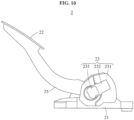
- the pedal apparatus 1 may be a pendant-type pedal apparatus as shown in FIGS. 10 and 11 .
- the spirit of example embodiments may also be applied to various other modified examples.
- the pedal apparatus 1 includes a pedal housing 11, the pedal pad 12, a pedal cover 13, a connecting link 14, a pedal arm 15, a magnet M, an elastic member 16, a sensing board 17, a plurality of terminals 18, and a pressurizing member 19.
- the pedal housing 11 includes an inner space 111 configured to receive various components such as the pedal arm 15 and the elastic member 16, a first rotation guide ring 112, and a first receiving recess 113.
- the pedal housing 11 may include a top wall, a bottom wall, and a side wall, and the inner space 111 may be opened toward an opposite side of the side wall.
- the first rotation guide ring 112 rotatably supports the pedal arm 15.
- the first rotation guide ring 112 is provided on an inner surface of the side wall of the pedal housing 11.
- the first rotation guide ring 112 may be, for example, a protrusion that protrudes from the side wall of the pedal housing 11.
- the first rotation guide ring 112 may be a groove that is recessed from the side wall of the pedal housing 11.
- the first receiving recess 113 may be provided on a lower inner surface of the pedal housing 11 to support one end of the elastic member 16.
- the pedal pad 12 rotates relative to the pedal housing 11.
- one side of the pedal pad 12 may be rotatably connected to the pedal housing 11.
- the pedal cover 13 is fastened to the pedal housing 11, and includes a cover body 131, a connector fastener 132, and a cover lid 133.
- the cover body 131 shields the opened portion of the inner space 111 of the pedal housing 11, thereby preventing an inflow of an external foreign substance into the inner space 111.
- the cover body 131 includes a board insertion space 1311, a support rib 1312, a board box 1313, and a second rotation guide ring 1314.
- the board insertion space 1311 is a space configured to receive the sensing board 17, and may be recessed toward a hollow 152 of the pedal arm 15.
- the board insertion space 1311 is exposed to an outside, and the sensing board 17 may be easily inserted through the exposed space.
- the support rib 1312 may be formed on an inner surface of the board insertion space 1311.
- the support rib 1312 may prevent a board end part 17b from moving backward when the plurality of terminals 18 are fastened to the board end part 17b of the sensing board 17.
- a plurality of support ribs 1312 may be provided to be spaced apart from each other such that end portions of the terminals 18 passing through the board end part 17b may be inserted into an interval or space between the support ribs 1312, thereby preventing the end portions of the terminals 18 from being obstructed by other members.
- the board box 1313 shields the board insertion space 1311 from the inner space 111 of the pedal housing 11.
- the board box 1313 may prevent a malfunction caused by fine particles generated by friction and coming in the sensing board 17 when the pedal arm 15 operates in the inner space 111 of the pedal housing 11.
- the second rotation guide ring 1314 rotatably supports the pedal arm 15.
- the second rotation guide ring 1314 and the first rotation guide ring 112 may be positioned on opposite sides.
- the second rotation guide ring 1314 and the first rotation guide ring 112 are engaged with a pair of coupling rings 151 of the pedal arm 15.
- the pedal arm 15 may be rotatably installed in the inner space 111 of the pedal housing 11. That is, a shaft structure that passes through the hollow 152 of the pedal arm 15 is unnecessary.
- the sensing board 17 may be positioned in the hollow 152.
- the connector fastener 132 may be a portion to which an external connector (not shown), to be electrically connected to the sensing board 17, is fastened.
- the external connector may be fastened to the connector fastener 132, and physically and electrically connected to the plurality of terminals 18 positioned in the connector fastener 132, thereby transmitting a signal sensed by a Hall sensor 171 of the sensing board 17 to the outside.
- the cover lid 133 may be fastened to the cover body 131 to shield the board insertion space 1311 from the outside, thereby preventing an inflow of a foreign substance into the sensing board 17.
- the cover lid 133 may be fixed to the cover body 131 using, for example, laser welding.
- the connecting link 14 may connect the pedal pad 12 and one end of the pedal arm 15 such that an angle of the pedal arm 15 may change based on a change in an angle of the pedal pad 12.
- the connecting link 14 may include a connecting body 141 rotatably connected to a bottom surface of the pedal pad 12, and a connecting head 142 formed at an end portion of the connecting body 141 and rotatably connected to the one end of the pedal arm 15.
- a thickness of a portion of the connecting body 141 connected to the connecting head 142 may be less than a thickness of the connecting head 142.
- the above structure may prevent a separation of the connecting link 14 from a connecting recess 153 of the pedal arm 15, without using a separate shaft structure.
- the pedal arm 15 may be disposed in the inner space 111 of the pedal housing 11, and rotate based on an angle of rotation of the pedal pad 12.
- the pedal arm 15 may be connected indirectly to the pedal pad 12 through the connecting link 14.
- the pedal arm 15 may include the pair of coupling rings 151, the hollow 152, the connecting recess 153, a separation preventing projection 154, a pair of guide plates 155, and a first support 156.
- the pair of coupling rings 151 may be disposed at both ends of the hollow 152, and may be respectively engaged with the first rotation guide ring 112 and the second rotation guide ring 1314 such that the pedal arm 15 may rotate about a predetermined virtual rotation axis.
- the hollow 152 may be a cylindrical hole that penetrates through the pedal arm 15, as shown in the drawings. Meanwhile, the hollow 152 may not necessarily have a cylindrical shape.
- the hollow 152 may be a hole having another shape, or may be a cavity that is recessed from one surface of the pedal arm 15.
- the hollow 152 may provide a space in which the sensing board 17 may be positioned.
- the hollow 152 When the pedal apparatus 1 is assembled, the hollow 152 may be disposed at a central portion of the pedal housing 11, that is, at a position sufficiently spaced apart from the outside.
- the sensing board 17 positioned in the hollow 152 may be insensitive to a disturbance such that an accuracy of measuring the angle of rotation of the pedal pad 12 may improve.
- the sensing board 17 is typically installed on an outer wall of the pedal apparatus 1.
- a sufficient air gap is generally formed between the sensing board 17 and the external space.
- the inner space 111 of the pedal housing 11 may sufficiently function as the air gap.
- the overall volume of the pedal apparatus 1 may be reduced.
- the connecting recess 153 may be a recess into which the connecting head 142 is to be inserted, and may be formed at the one end of the pedal arm 15.
- the connecting recess 153 may be formed in a cylindrical shape with a size and a diameter corresponding to the connecting head 142.
- An upper side of the connecting recess 153 may be opened such that the connecting body 141 extending from the connecting head 142 may be exposed.
- the separation preventing projection 154 may be provided on at least a portion of the opened upper side of the connecting recess 153 to support an upper side of the connecting head 142 such that the connecting head 142 laterally inserted into the connecting recess 153 may not be separated upward.
- the pair of guide plates 155 may be construed as both side surfaces of the pedal arm 15.
- the pressurizing member 19 may be disposed between the pair of guide plates 155, which will be described later.
- the above structure may prevent a separation of the pressurizing member 19 from the pedal arm 15, and also guide the pressurizing member 19 to stably rotate with respect to the pedal arm 15.
- the first support 156 may be a curved surface formed on a bottom surface of the one end of the pedal arm 15, and may support one end of the pressurizing member 19.
- the first support 156 may be construed as a portion of the bottom surface of the connecting recess 153.
- the elastic member 16 may be disposed between a middle part of the pressurizing member 19 and the lower inner surface of the pedal housing 11, to provide an elastic force to press the pressurizing member 19 upward.
- the elastic member 16 may provide the elastic force to rotate the pedal pad 12 in a direction away from the pedal housing 11.
- the magnet M may be installed in the pedal arm 15.
- the magnet M may be fixed and installed in the pedal arm 15 using insert injection in a process of manufacturing the pedal arm 15.
- the magnet M may be installed on a surface of the inner wall of the hollow 152 and the magnet M may be exposed through the hollow 152.
- the magnet M may be positioned closer to the sensing board 17 when compared to a case in which the magnet M is installed to be mounted in the pedal arm 15, such that the magnet M may not be exposed through the hollow 152.
- a strength of a magnetic field generated by the magnet M and sensed by the sensing board 17 may increase.
- a plurality of magnets M may be provided.
- magnets that generate relatively strong magnetic fields for example, rare earth magnets, particularly, neodymium magnets
- sizes and quantities of the magnets may be reduced.
- a plurality of magnets with relatively high supply and price stability for example, ferrite magnets, may be used.
- the types and the number of the magnets M may be modified variously.
- the sensing board 17 may transmit information related to the angle of rotation of the pedal pad 12 to the outside through the terminals 18. At least a portion of the sensing board 17 may be inserted into the hollow 152.
- the sensing board 17 may include the Hall sensor 171 configured to sense a magnetic force generated by the magnet M, and a terminal fastening hole 172 through which the plurality of terminals 18 are fastened thereto.
- the Hall sensor 171 may be positioned in the hollow 152, for example, on the rotation axis of the pedal arm 15.
- the Hall sensor 171 may sense a change in the magnetic field generated by the magnet M.
- the Hall sensor 171 may sense an amount of rotation of the pedal arm 15 to which the magnet M is fixed.
- the sensing board 17 may be divided into a board main part 17a on which the Hall sensor 171 is installed, and the board end part 17b including the terminal fastening hole 172.
- a width of the board end part 17b may be greater than a width of the board main part 17a such that the sensing board 17 may not be inserted into the board insertion space 1311 in excess of a predetermined length.
- the plurality of terminals 18 may be positioned in the connector fastener 132, and electrically connected to the external connector (not shown) fastened to the connector fastener 132, thereby transmitting an electrical signal of the sensing board 17 to the outside.
- the plurality of terminals 18 may be installed in a direction perpendicular to the sensing board 17, as shown in FIGS. 2 and 3 . By the above structure, the plurality of terminals 18 may be inserted through the connector fastener 132, and simply installed on the sensing board 17 using press fit.
- the connector fastener 132 may be disposed in a direction perpendicular to the sensing board 17, and the terminals 18 may be definitely coupled to the sensing board 17 using press fit.
- the connector fastener 132 and the cover body 131 may be formed as an integral body using injection molding. That is, through the structure described in the example embodiments, the number of components may be reduced, and thus time and costs for manufacturing may be reduced.
- a coupling force of the sensing board 17 and the terminals 18 may structurally improve without using a separate medium.
- oscillation horizontally applied to the sensing board 17 may be attenuated by the terminals 18, and oscillation horizontally applied to the terminals 18 may be attenuated by the sensing board 17.
- a structure robust against oscillation may be provided.
- the pressurizing member 19 may press the inner wall of the pedal housing 11 when the user controls the pedal pad 12.
- the one end of the pressurizing member 19 may be supported by a lower side of the one end of the pedal arm 15, and another end of the pressurizing member 19 may be positioned between an upper inner surface of the pedal housing 11 and the hollow 152 of the pedal arm 15.
- the pressurizing member 19 may include a pressurizing lever 191 configured to rotate with respect to the pedal arm 15, a second support 193 positioned at one end of the pressurizing lever 191, a friction pad 192 positioned at another end of the pressurizing lever 191, a stopping projection 194 to be stopped by an end portion of the pedal arm 15 such that the pressurizing lever 191 may not be separated from the pedal arm 15, and a second receiving recess 195 formed on a bottom surface of the pressurizing lever 191 to support another end of the elastic member 16.
- the friction pad 192 may be a member that produces friction when rubbed against the inner wall of the pedal housing 11, and may include, for example, a material having a more excellent frictional force than the pressurizing lever 191.
- the second support 193 may be a curved surface formed on a top surface of the one end of the pressurizing member 19, and may support a lower end of an outer circumferential surface of the first support 156 of the pedal arm 15.
- the second support 193 may be formed to have the same or similar curvature as the first support 156, and may support the pedal arm 15 such that the pressurizing member 19 may rotate with respect to the pedal arm 15 as shown in FIG. 7 .
- a pair of second supports 193 may be disposed on both sides from the stopping projection 194.
- the one end of the pedal arm 15 may rotate downward and the elastic member 16 may be compressed such that an elastic force may increase and a reaction force applied to the pressurizing member 19 may also increase.
- the reaction force by the elastic member 16 may be concentrated on the pressurizing member 19 such that the friction pad 192 at the other end of the pressurizing member 19 may be rubbed against the inner surface of the pedal housing 11 with a further increased frictional force.
- the pressurizing member 19 since the pressurizing member 19 is separated from the pedal arm 15, a load generated as the pedal pad 12 is pressed may be concentrated on the friction pad 192, rather than the pair of rotation guide rings 112 and 1314 supporting the pedal arm 15.
- the frictional force of the friction pad 192 may increase while abrasion of the rotation guide rings 112 and 1314 and the coupling rings 151 may be minimized, and a movement of the pedal arm 15 from the rotation guide rings 112 and 1314 may be prevented, whereby a value measured by the sensing board 17 may be stably output.
- the one end of the pedal arm 15 may rotate and return to the original upper position by the elastic force of the elastic member 16, and the compressed elastic member 16 may be restored such that the elastic force may gradually decrease and the reaction force applied to the pressurizing member 19 may also decrease.
- the elastic force used to restore the elastic member 16 may also be used to assist the pedal arm 15 to move upward and the frictional force with which the friction pad 192 is rubbed against the inner surface of the pedal housing 11 may decrease. Thus, a hysteresis between a pressing force and a releasing force with respect to the pedal pad 12 may occur.
- the pressurizing member 19 configured to rotate relative to the pedal arm 15 may be rubbed against the inner surface of the pedal housing 11, thereby increasing the frictional force and also causing the hysteresis.
- the number of components may be reduced and production costs may also be reduced.
- the method of manufacturing the pedal apparatus 1 may include an operation of manufacturing a pedal cover by forming the cover body 131 and the connector fastener 132 as an integral body using injection molding, an operation of inserting a sensing board including a Hall sensor from an outside in a direction perpendicular to a surface of the pedal cover such that the Hall sensor may be positioned in a hollow of a pedal arm, and an operation of inserting a plurality of terminals configured to transmit a signal sensed by the Hall sensor to the outside in a direction perpendicular to the sensing board such that the plurality of terminals may be installed on the sensing board.
- the sensing board 17 Before the cover lid 133 is installed, the sensing board 17 may be inserted and installed in the board insertion space 1311 in a direction parallel to the rotation axis of the pedal arm 15. Further, when the sensing board 17 is installed, the plurality of terminals 18 may be inserted in a direction perpendicular to the rotation axis of the pedal arm 15 and fastened to the sensing board 17 through the connector fastener 132.
- a Hall sensor configured to sense a magnetic field may be positioned in a hollow of a pedal arm, whereby a sufficient separation distance from an outside to the Hall sensor may be secured.
- the Hall sensor may be insensitive to a disturbance and thereby measure a position of a pedal with an improved accuracy.
- a separate air gap to prevent an effect of the disturbance is unnecessary, and thus the overall volume of a pedal apparatus may be reduced.
- a sensing board and terminals may be installed in perpendicular directions, and thus a process and costs for connecting the terminals to the sensing board may be reduced, a coupling force of the sensing board and the terminals may structurally improve without using a separate medium, and a structure robust against vertical and horizontal oscillation may be provided.
- a connector fastener and a pedal cover may be formed as an integral body, and thus the total number of components may be reduced and manufacturing costs and efforts may also be reduced.
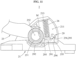
- FIG. 10 is a side view illustrating a pedal apparatus according to an example embodiment
- FIG. 11 illustrates the pedal apparatus FIG. 10 with a pedal cover removed.
- a pedal apparatus 2 may include a pedal housing 21, a pedal pad 22, a pedal cover 23, a pedal arm 25, a magnet M, an elastic member 26, a sensing board (not shown), a plurality of terminals (not shown), and a pressurizing member 29.
- the pedal housing 21 may include a hole through which the pedal arm 25 passes such that the pedal arm 25 may extend to be connected to the pedal pad 22.
- the pedal housing 21 may include an inner space 211, a first rotation guide ring (not shown), and a first receiving recess 213.
- the first receiving recess 213 may be provided on an upper inner surface of the pedal housing 21 to support an upper end of the elastic member 26.
- the pedal pad 22 may be connected directly to the pedal arm 25, for example, without using a separate connecting link, and transmit a pedal force of a user to the pedal arm 25.
- the pedal cover 23 may include a cover body 231, a connector fastener 232, and a cover lid 233. Similar to the example embodiment described above, the cover body 231 may include a board insertion space (not shown), a support rib (not shown), a board box (not shown), and a second rotation guide ring (not shown).
- the pedal arm 25 may include a pair of coupling rings 251, a hollow 252, a pair of guide plates 255, and a first support 256.
- the first support 256 may be a curved surface formed on a top surface of one end of the pedal arm 25, and support one end of the pressurizing member 29.
- the elastic member 26 may be disposed between a middle part of the pressurizing member 29 and the upper inner surface of the pedal housing 21, to provide an elastic force to press the pressurizing member 29 downward. Thus, the elastic member 26 may provide the elastic force to move the pedal pad 22 upward.
- the sensing board may include a Hall sensor and a terminal fastening hole, and may be divided into a board main part on which the Hall sensor is installed and a board end part including the terminal fastening hole.
- the pressurizing member 29 may include a pressurizing lever 291, a second support 293, a friction pad 292, and a second receiving recess 295.
- the second support 293 may be a curved surface formed on a bottom surface of the one end of the pressurizing member 29, and may support an upper end of an outer circumferential surface of the first support 256 of the pedal arm 25.
- the second receiving recess 295 may be formed on a top surface of the pressurizing lever 291 to support a lower end of the elastic member 26.
- FIG. 12 is a cross-sectional view illustrating a pedal apparatus according to an example embodiment
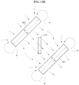
- FIGS. 13A and 13B illustrate a distribution of magnetic force lines formed by a pair of magnets when the pedal apparatus of FIG. 12 operates.
- a board box is omitted from FIG. 12 .
- a pedal apparatus 3 may include a pair of magnets M1 and M2 positioned on opposite sides from the Hall sensor 171 of the sensing board 17.
- the pair of magnets M1 and M2 may be disposed such that facing surfaces thereof may have opposite magnetisms or polarities.
- almost linear magnetic force lines may be formed in a space between the pair of magnets M1 and M2, as shown in FIGS. 13A and 13B .
- the Hall sensor 171 may sense a change in directions of the magnetic force lines, thereby sensing a change in an angle of the pedal arm 15.
- the Hall sensor 171 may be disposed at a position other than a set position. If a single magnet is provided, an effect of a magnetic field formed by the single magnet on the Hall sensor 171 in response to a change in the angle of the pedal arm 15 may differ from what is expected. That is, in a case in which the position of the Hall sensor 171 changes in upward/downward/leftward/rightward directions due to an assembly tolerance when the pedal arm 15 operates, the effect on the Hall sensor 171 in response to the change in the angle of the pedal arm 15 may be different from what is expected. Thus, such a difference may decrease an accuracy of measuring the angle of the pedal pad 12.
- a Hall sensor configured to sense a magnet field may be positioned in a hollow of a pedal arm, whereby a sufficiency separation distance from an outside to the Hall sensor may be secured.
- the Hall sensor may be insensitive to a disturbance and thereby measure a position of a pedal with an improved accuracy.
- a sensing board and terminals may be installed in perpendicular directions, and thus a process and costs for connecting the terminals to the sensing board may be reduced, a coupling force of the sensing board and the terminals may structurally improve without using a separate medium, and a structure robust against vertical and horizontal oscillation may be provided.
- a connector fastener and a pedal cover may be formed as an integral body, and thus the total number of components may be reduced and manufacturing costs and efforts may also be reduced.
Landscapes
- Engineering & Computer Science (AREA)
- Physics & Mathematics (AREA)
- General Physics & Mathematics (AREA)
- Automation & Control Theory (AREA)
- Manufacturing & Machinery (AREA)
- Combustion & Propulsion (AREA)
- Chemical & Material Sciences (AREA)
- Transportation (AREA)
- Mechanical Engineering (AREA)
- Mechanical Control Devices (AREA)
- Details Of Connecting Devices For Male And Female Coupling (AREA)
- Measurement Of Length, Angles, Or The Like Using Electric Or Magnetic Means (AREA)
- Braking Elements And Transmission Devices (AREA)
Claims (13)
- Pedalvorrichtung (1), die Folgendes umfasst:ein Pedalgehäuse (11) mit einem inneren Raum (111);eine Pedalplatte (12), die zum Drehen relativ zu dem Pedalgehäuse (11) konfiguriert ist;einen Pedalarm (15), der zum Drehen auf der Basis eines Drehwinkels der Pedalplatte (12) direkt oder indirekt mit der Pedalplatte (12) verbunden ist, wobei der Pedalarm (15) einen Hohlraum (152) aufweist;einen in dem Pedalarm (15) installierten Magneten (M);eine Sensorplatine (17) mit einem Hall-Sensor (171), der zum Erfassen einer von dem Magneten erzeugten Magnetkraft konfiguriert ist, wobei mindestens ein Abschnitt der Sensorplatine (17) in den Hohlraum (152) eingeführt ist, undeine Pedalabdeckung (13) mit einem Abdeckungskörper (131), der zum Abschirmen des inneren Raums (111) des Pedalgehäuses (11) konfiguriert ist,wobei der Pedalarm (15) ferner ein Paar Kupplungsringe (151) aufweist, die jeweils an beiden Enden des Hohlraums (152) angeordnet sind, und das Paar Kupplungsringe (151) jeweils mit einem an einer Innenfläche des Pedalgehäuses (11) ausgebildeten ersten Drehführungsring (112) und einem an einer Innenfläche des Abdeckungskörpers (131) ausgebildeten zweiten Drehführungsring (1314) in Eingriff ist, so dass sich der Pedalarm (15) um eine vorbestimmte Drehachse dreht,dadurch gekennzeichnet, dass der Abdeckungskörper (131) Folgendes umfasst:einen Platineneinführraum (1311), der in Richtung des Hohlraums (152) ausgespart ist; undeine Platinenbox, die zum Abschirmen des Platineneinführraums (1311) vom inneren Raum (111) des Pedalgehäuses (11) konfiguriert ist.
- Pedalvorrichtung (11) nach Anspruch 1, wobei der Hall-Sensor (171) auf der Drehachse positioniert ist.
- Pedalvorrichtung (l) nach Anspruch 1 oder 2, wobei die Pedalabdeckung (13) ferner Folgendes beinhaltet:ein Verbinderbefestigungselement (132), an dem ein mit der Sensorplatine (17) elektrisch verbundener Verbinder zum Übertragen eines vom Hall-Sensor (171) erfassten Signals nach außen befestigt ist,wobei die Pedalvorrichtung (1) ferner Folgendes umfasst:
mehrere mit dem Verbinder elektrisch zu verbindende Anschlussklemmen (18), wobei die mehreren Anschlussklemmen (18) in dem Verbinderbefestigungselement positioniert und in einer Richtung lotrecht zur Sensorplatine (17) installiert sind. - Pedalvorrichtung (1) nach Anspruch 3, wobei das Verbinderbefestigungselement (132) und der Abdeckungskörper (131) als einstückiger Körper ausgebildet sind.
- Pedalvorrichtung (1) nach Anspruch 3 oder 4, wobei die Sensorplatine (17) Folgendes umfasst:ein Platinenhauptteil (17a), an dem der Hall-Sensor (171) installiert ist; undein Platinenendteil (17b) mit einem Anschlussklemmenbefestigungsloch (172), durch das die mehreren Anschlussklemmen (18) daran befestigt werden,wobei eine Breite des Platinenendteils (17b) größer ist als eine Breite des Platinenhauptteils (17a), so dass die Sensorplatine (17) nicht über eine vorbestimmte Länge hinaus in den Platineneinführraum (1311) eingeführt wird.
- Pedalvorrichtung (1) nach Anspruch 5, wobei die Pedalabdeckung (13) ferner Folgendes beinhaltet:eine Stützrippe (1312), die an einer Innenfläche des Platineneinführraums (1311) ausgebildet ist,wobei die Stützrippe (1312) zum Verhindern einer Bewegung des Platinenendteils nach hinten konfiguriert ist, wenn die mehreren Anschlussklemmen (18) am Platinenendteil befestigt sind.
- Pedalvorrichtung (1) nach Anspruch 4, wobei die Pedalabdeckung (13) ferner Folgendes aufweist:
einen Abdeckungsdeckel (233), der zum Abschirmen des Platineneinführraums (1311) vor der Außenseite konfiguriert ist. - Pedalvorrichtung (1) nach einem vorherigen Anspruch, die ferner Folgendes umfasst:ein Verbindungsglied (14), das zum Verbinden der Pedalplatte (12) und eines Endes des Pedalarms (15) konfiguriert ist;ein Druckbeaufschlagungselement (29), von dem ein Ende von einer Unterseite des einen Endes des Pedalarms (15) getragen wird und das andere Ende zwischen einer oberen Innenfläche des Pedalgehäuses (11) und der Drehachse vorgesehen ist; undein elastisches Element (26), das zwischen einem mittleren Teil des Druckbeaufschlagungselements (29) und einer unteren Innenfläche des Pedalgehäuses (11) angeordnet ist.
- Pedalvorrichtung (1) nach einem vorherigen Anspruch, die ferner Folgendes umfasst:ein Druckbeaufschlagungselement (29), von dem ein Ende von einer Oberseite eines Endes des Pedalarms (15) getragen wird und ein anderes Ende zwischen einer unteren Innenfläche des Pedalgehäuses (11) und der Drehachse vorgesehen ist; undein elastisches Element (26), das zwischen einem mittleren Teil des Druckbeaufschlagungselements (29) und einer oberen Innenfläche des Pedalgehäuses (11) angeordnet ist.
- Pedalvorrichtung (1) nach einem vorherigen Anspruch, wobei der Magnet (M) ein Paar auf gegenüberliegenden Seiten des Hall-Sensors (171) angeordneter Magnete (Ml, M2) umfasst, und
einander zugewandte Flächen des Magnetpaares (Ml, M2) entgegengesetzte Magnetismen aufweisen. - Verfahren zur Herstellung einer Pedalvorrichtung (1) mit einer Pedalplatte (12), einem Pedalgehäuse (11), einem in einem Innenraum (111) des Pedalgehäuses (11) installierten Pedalarm (15), wobei der Pedalarm (15) zum Drehen als Reaktion auf eine Betätigung der Pedalplatte (12) konfiguriert ist, und einer Pedalabdeckung (13), die zum Abschirmen des inneren Raums (111) des Pedalgehäuses (11) konfiguriert ist, wobei das Verfahren Folgendes beinhaltet:Einführen einer Sensorplatine (17) mit einem Hall-Sensor (171) von außen in einer Richtung lotrecht zu einer Fläche der Pedalabdeckung (13), so dass der Hall-Sensor (171) in einem Hohlraum (152) des Pedalarms (15) positioniert ist; undEinführen mehrerer Anschlussklemmen (18), die zum Übertragen eines vom Hall-Sensor (171) erfassten Signals zur Außenseite in einer Richtung lotrecht zur Sensorplatine (17) konfiguriert sind, so dass die mehreren Anschlussklemmen (18) auf der Sensorplatine (17) installiert sind.
- Verfahren nach Anspruch 11, wobei die mehreren Anschlussklemmen (18) auf der Sensorplatine (17) mittels Presspassung installiert werden.
- Verfahren nach Anspruch 11 oder 12, wobei die Pedalabdeckung (13) Folgendes aufweist:ein Verbinderbefestigungselement (132), an dem ein Verbinder befestigt ist, der zum Übertragen des vom Hall-Sensor (171) erfassten Signals zur Außenseite elektrisch mit der Sensorplatine (17) verbunden ist,wobei die mehreren Anschlussklemmen (18) durch das Verbinderbefestigungselement (132) eingeführt und an der Sensorplatine (17) installiert werden.
Applications Claiming Priority (2)
| Application Number | Priority Date | Filing Date | Title |
|---|---|---|---|
| KR20170028253 | 2017-03-06 | ||
| KR1020180017298A KR102048736B1 (ko) | 2017-03-06 | 2018-02-12 | 페달 장치 및 그 제조 방법 |
Publications (2)
| Publication Number | Publication Date |
|---|---|
| EP3376333A1 EP3376333A1 (de) | 2018-09-19 |
| EP3376333B1 true EP3376333B1 (de) | 2023-06-07 |
Family
ID=61598866
Family Applications (1)
| Application Number | Title | Priority Date | Filing Date |
|---|---|---|---|
| EP18160080.0A Active EP3376333B1 (de) | 2017-03-06 | 2018-03-06 | Pedalvorrichtung und herstellungsverfahren dafür |
Country Status (4)
| Country | Link |
|---|---|
| US (1) | US10248152B2 (de) |
| EP (1) | EP3376333B1 (de) |
| JP (1) | JP6581678B2 (de) |
| CN (1) | CN108528213B (de) |
Families Citing this family (28)
| Publication number | Priority date | Publication date | Assignee | Title |
|---|---|---|---|---|
| KR102003718B1 (ko) * | 2018-04-23 | 2019-07-25 | 경창산업주식회사 | 히스테리시스 발생 구조를 갖는 차량용 가속 페달 |
| CN112041190B (zh) * | 2018-05-02 | 2024-04-09 | 海拉有限双合股份公司 | 用于车辆的立式踏板 |
| JP7067457B2 (ja) * | 2018-12-20 | 2022-05-16 | 株式会社デンソー | アクセル装置 |
| KR102054470B1 (ko) * | 2019-02-08 | 2019-12-10 | 경창산업주식회사 | 이중 히스테리시스 생성 구조를 갖는 차량용 가속 페달 |
| US10976766B2 (en) * | 2019-03-15 | 2021-04-13 | Sl Corporation | Pedal device for vehicle |
| JP7281667B2 (ja) * | 2019-03-27 | 2023-05-26 | パナソニックIpマネジメント株式会社 | 建設機械用ペダルスイッチ及び建設機械 |
| KR102684307B1 (ko) * | 2019-04-08 | 2024-07-31 | 현대자동차주식회사 | 가속페달용 킥 다운 스위치 및 이를 이용한 가속페달의 오조작시 제어방법 |
| DE112020002307T5 (de) | 2019-05-09 | 2022-02-17 | Cts Corporation | Fahrzeugbremspedal mit pedalwiderstandsbaugruppe und kraft-/positionssensor |
| JP7095652B2 (ja) * | 2019-05-21 | 2022-07-05 | 株式会社デンソー | アクセル装置 |
| JP7334560B2 (ja) * | 2019-09-26 | 2023-08-29 | 日本精機株式会社 | 回転角度検出装置 |
| KR102817378B1 (ko) * | 2019-11-15 | 2025-06-09 | 현대자동차주식회사 | 자율주행 차량용 폴더블 오르간타입 페달장치 |
| KR102692360B1 (ko) * | 2019-12-12 | 2024-08-05 | 현대자동차주식회사 | 차량용 가속 페달 |
| JP7400701B2 (ja) * | 2020-11-19 | 2023-12-19 | 株式会社デンソー | アクセル装置 |
| CN116917172A (zh) | 2021-01-13 | 2023-10-20 | Cts公司 | 车辆踏板阻力阻尼组件 |
| JP7452467B2 (ja) | 2021-02-25 | 2024-03-19 | 株式会社デンソー | ペダル装置 |
| JP7444105B2 (ja) | 2021-02-25 | 2024-03-06 | 株式会社デンソー | ペダル装置 |
| JP2022130116A (ja) | 2021-02-25 | 2022-09-06 | 株式会社デンソー | ペダル装置 |
| KR20230027672A (ko) * | 2021-08-19 | 2023-02-28 | 현대자동차주식회사 | 폴더블 전자식 페달장치 |
| CN118076521A (zh) | 2021-10-11 | 2024-05-24 | Cts公司 | 带位置传感器的车辆踏板弹簧阻尼模拟器组件 |
| JP7815797B2 (ja) | 2022-01-26 | 2026-02-18 | 株式会社デンソー | ブレーキペダル装置 |
| WO2023143919A1 (de) * | 2022-01-27 | 2023-08-03 | HELLA GmbH & Co. KGaA | Fahrpedal mit einem drehstellungssensor mit einer sensordrehachse und einem schwenkbaren betätigungselement mit einer betätigungsdrehachse |
| US12524032B2 (en) | 2022-06-15 | 2026-01-13 | KSR IP Holdings, LLC | Floor mounted pedal assembly |
| DE112023003672T5 (de) * | 2022-09-02 | 2025-08-07 | KSR IP Holdings, LLC | Passive Pedalkraft-Emulator-Baugruppen |
| US12090980B2 (en) | 2022-09-06 | 2024-09-17 | Cts Corporation | Brake pedal emulator |
| JP1782057S (ja) * | 2022-09-08 | 2024-10-10 | 車両用アクセルペダル | |
| KR20240109660A (ko) | 2023-01-04 | 2024-07-12 | 현대자동차주식회사 | 전자식 브레이크페달 장치 |
| JP1764518S (ja) * | 2023-06-05 | 2024-02-28 | 車両用アクセルペダル | |
| CN119305515B (zh) * | 2024-12-16 | 2025-03-18 | 隆中控股集团股份有限公司 | 一种电子制动踏板 |
Citations (2)
| Publication number | Priority date | Publication date | Assignee | Title |
|---|---|---|---|---|
| JP2007276707A (ja) * | 2006-04-10 | 2007-10-25 | Tsuda Industries Co Ltd | 自動車用のアクセルペダルユニット |
| JP2016113113A (ja) * | 2014-12-17 | 2016-06-23 | トヨタ自動車株式会社 | アクセルペダル装置 |
Family Cites Families (15)
| Publication number | Priority date | Publication date | Assignee | Title |
|---|---|---|---|---|
| JP2003025864A (ja) * | 2001-07-17 | 2003-01-29 | Nissan Motor Co Ltd | アクセルペダル装置の取付構造 |
| JP2004093287A (ja) * | 2002-08-30 | 2004-03-25 | Denso Corp | 回転角検出装置 |
| DE10258285A1 (de) * | 2002-12-13 | 2004-06-24 | Robert Bosch Gmbh | Fahrpedalmodul |
| DE10325495A1 (de) * | 2003-06-04 | 2004-12-30 | Zf Boge Elastmetall Gmbh | Pedalsystem |
| KR100718541B1 (ko) | 2005-12-13 | 2007-05-15 | 주식회사 동희산업 | 기계 오르간식 가속페달 장치 |
| DE102006035882B4 (de) * | 2006-07-31 | 2008-05-29 | MÄNNLE, Erik | Pedalanordnung mit einem stehenden Pedal |
| JP5279509B2 (ja) * | 2006-12-27 | 2013-09-04 | ヒルタ工業株式会社 | ペダル装置 |
| JP2008238908A (ja) * | 2007-03-27 | 2008-10-09 | Mikuni Corp | アクセルペダル装置 |
| DE102008046652B4 (de) * | 2007-10-29 | 2021-06-02 | Volkswagen Ag | Fußpedal an Kraftfahrzeugen |
| DE102010020314A1 (de) * | 2010-05-12 | 2011-11-17 | Erik Männle | Pedalanordnung, insbesondere für Fahrzeuge oder Kraftfahrzeuge |
| JP5743789B2 (ja) * | 2011-08-02 | 2015-07-01 | 株式会社ミクニ | アクセルペダル装置 |
| US8997605B2 (en) * | 2012-05-18 | 2015-04-07 | Ksr Ip Holdings Llc. | Pedal assembly with heel/leg point crash shock absorption |
| KR101518899B1 (ko) | 2013-07-12 | 2015-05-11 | 현대자동차 주식회사 | 차량용 가속페달 각도 검지장치 |
| JP6406015B2 (ja) * | 2015-01-06 | 2018-10-17 | 株式会社デンソー | アクセル装置、及び、アクセル装置の金型装置 |
| WO2018152101A1 (en) * | 2017-02-14 | 2018-08-23 | Cts Corporation | Active vibratory pedal with haptic motor power connection assembly |
-
2018
- 2018-03-01 JP JP2018036069A patent/JP6581678B2/ja not_active Expired - Fee Related
- 2018-03-06 EP EP18160080.0A patent/EP3376333B1/de active Active
- 2018-03-06 US US15/913,103 patent/US10248152B2/en active Active
- 2018-03-06 CN CN201810183134.XA patent/CN108528213B/zh active Active
Patent Citations (2)
| Publication number | Priority date | Publication date | Assignee | Title |
|---|---|---|---|---|
| JP2007276707A (ja) * | 2006-04-10 | 2007-10-25 | Tsuda Industries Co Ltd | 自動車用のアクセルペダルユニット |
| JP2016113113A (ja) * | 2014-12-17 | 2016-06-23 | トヨタ自動車株式会社 | アクセルペダル装置 |
Also Published As
| Publication number | Publication date |
|---|---|
| EP3376333A1 (de) | 2018-09-19 |
| JP2018147483A (ja) | 2018-09-20 |
| CN108528213B (zh) | 2021-12-17 |
| JP6581678B2 (ja) | 2019-09-25 |
| CN108528213A (zh) | 2018-09-14 |
| US20180253120A1 (en) | 2018-09-06 |
| US10248152B2 (en) | 2019-04-02 |
Similar Documents
| Publication | Publication Date | Title |
|---|---|---|
| EP3376333B1 (de) | Pedalvorrichtung und herstellungsverfahren dafür | |
| US9383279B2 (en) | Installation structure for pedal stroke sensor | |
| EP2192037B1 (de) | Drosselklappensteuerung mit einem Winkelpositionssensor | |
| US20060117902A1 (en) | Pedal assembly with an integrated non-contact rotational position sensor | |
| JP7452467B2 (ja) | ペダル装置 | |
| US8330456B2 (en) | Rotational angle sensing device | |
| US20080184843A1 (en) | Accelerator Pedal Module With Magnetic Sensor | |
| CN102401628B (zh) | 旋转角度检测单元 | |
| US12000446B2 (en) | Drum brake having a load measurement device | |
| CN110121458B (zh) | 扭矩传感器及包括其的转向装置 | |
| EP1345005A1 (de) | Drehwinkelsensor mit wasserdichter und explosionsgeschützter Struktur | |
| US20250018904A1 (en) | Control pedal device | |
| CN101909540A (zh) | 传感器装置 | |
| KR102048736B1 (ko) | 페달 장치 및 그 제조 방법 | |
| US8001870B2 (en) | Accelerator | |
| CN104736985B (zh) | 压力传感器 | |
| KR101272010B1 (ko) | 미소 변위 측정 센서 | |
| JP2021190297A (ja) | 樹脂成形体 | |
| US9702416B2 (en) | Linear sensor | |
| CZ20023251A3 (cs) | Měřicí zařízení k bezdotykovému zjišťování úhlu natočení u uspořádání pedálu | |
| KR102535655B1 (ko) | 압력센서 | |
| JP3724747B2 (ja) | 非接触式液面レベルセンサ | |
| JP2005091275A (ja) | 回転角センサ | |
| JP2018133547A (ja) | コイル組立体およびブレーキ制御装置 | |
| EP3312564B1 (de) | Vorrichtung zur rotationswinkeldetektion und darin verwendete winkelsensoreinheit |
Legal Events
| Date | Code | Title | Description |
|---|---|---|---|
| PUAI | Public reference made under article 153(3) epc to a published international application that has entered the european phase |
Free format text: ORIGINAL CODE: 0009012 |
|
| STAA | Information on the status of an ep patent application or granted ep patent |
Free format text: STATUS: REQUEST FOR EXAMINATION WAS MADE |
|
| 17P | Request for examination filed |
Effective date: 20180306 |
|
| AK | Designated contracting states |
Kind code of ref document: A1 Designated state(s): AL AT BE BG CH CY CZ DE DK EE ES FI FR GB GR HR HU IE IS IT LI LT LU LV MC MK MT NL NO PL PT RO RS SE SI SK SM TR |
|
| AX | Request for extension of the european patent |
Extension state: BA ME |
|
| RIC1 | Information provided on ipc code assigned before grant |
Ipc: G05G 1/44 20080401ALI20180810BHEP Ipc: H01R 43/20 20060101ALI20180810BHEP Ipc: G05G 1/38 20080401AFI20180810BHEP |
|
| STAA | Information on the status of an ep patent application or granted ep patent |
Free format text: STATUS: EXAMINATION IS IN PROGRESS |
|
| 17Q | First examination report despatched |
Effective date: 20210818 |
|
| RIC1 | Information provided on ipc code assigned before grant |
Ipc: G05G 1/50 20080401ALI20220530BHEP Ipc: G05G 1/44 20080401ALI20220530BHEP Ipc: G05G 1/38 20080401AFI20220530BHEP |
|
| GRAP | Despatch of communication of intention to grant a patent |
Free format text: ORIGINAL CODE: EPIDOSNIGR1 |
|
| STAA | Information on the status of an ep patent application or granted ep patent |
Free format text: STATUS: GRANT OF PATENT IS INTENDED |
|
| INTG | Intention to grant announced |
Effective date: 20230202 |
|
| GRAS | Grant fee paid |
Free format text: ORIGINAL CODE: EPIDOSNIGR3 |
|
| GRAA | (expected) grant |
Free format text: ORIGINAL CODE: 0009210 |
|
| STAA | Information on the status of an ep patent application or granted ep patent |
Free format text: STATUS: THE PATENT HAS BEEN GRANTED |
|
| AK | Designated contracting states |
Kind code of ref document: B1 Designated state(s): AL AT BE BG CH CY CZ DE DK EE ES FI FR GB GR HR HU IE IS IT LI LT LU LV MC MK MT NL NO PL PT RO RS SE SI SK SM TR |
|
| REG | Reference to a national code |
Ref country code: GB Ref legal event code: FG4D |
|
| REG | Reference to a national code |
Ref country code: CH Ref legal event code: EP Ref country code: AT Ref legal event code: REF Ref document number: 1576998 Country of ref document: AT Kind code of ref document: T Effective date: 20230615 |
|
| REG | Reference to a national code |
Ref country code: DE Ref legal event code: R096 Ref document number: 602018050668 Country of ref document: DE |
|
| REG | Reference to a national code |
Ref country code: LT Ref legal event code: MG9D |
|
| REG | Reference to a national code |
Ref country code: NL Ref legal event code: MP Effective date: 20230607 |
|
| PG25 | Lapsed in a contracting state [announced via postgrant information from national office to epo] |
Ref country code: SE Free format text: LAPSE BECAUSE OF FAILURE TO SUBMIT A TRANSLATION OF THE DESCRIPTION OR TO PAY THE FEE WITHIN THE PRESCRIBED TIME-LIMIT Effective date: 20230607 Ref country code: NO Free format text: LAPSE BECAUSE OF FAILURE TO SUBMIT A TRANSLATION OF THE DESCRIPTION OR TO PAY THE FEE WITHIN THE PRESCRIBED TIME-LIMIT Effective date: 20230907 Ref country code: ES Free format text: LAPSE BECAUSE OF FAILURE TO SUBMIT A TRANSLATION OF THE DESCRIPTION OR TO PAY THE FEE WITHIN THE PRESCRIBED TIME-LIMIT Effective date: 20230607 |
|
| REG | Reference to a national code |
Ref country code: AT Ref legal event code: MK05 Ref document number: 1576998 Country of ref document: AT Kind code of ref document: T Effective date: 20230607 |
|
| PG25 | Lapsed in a contracting state [announced via postgrant information from national office to epo] |
Ref country code: RS Free format text: LAPSE BECAUSE OF FAILURE TO SUBMIT A TRANSLATION OF THE DESCRIPTION OR TO PAY THE FEE WITHIN THE PRESCRIBED TIME-LIMIT Effective date: 20230607 Ref country code: NL Free format text: LAPSE BECAUSE OF FAILURE TO SUBMIT A TRANSLATION OF THE DESCRIPTION OR TO PAY THE FEE WITHIN THE PRESCRIBED TIME-LIMIT Effective date: 20230607 Ref country code: LV Free format text: LAPSE BECAUSE OF FAILURE TO SUBMIT A TRANSLATION OF THE DESCRIPTION OR TO PAY THE FEE WITHIN THE PRESCRIBED TIME-LIMIT Effective date: 20230607 Ref country code: LT Free format text: LAPSE BECAUSE OF FAILURE TO SUBMIT A TRANSLATION OF THE DESCRIPTION OR TO PAY THE FEE WITHIN THE PRESCRIBED TIME-LIMIT Effective date: 20230607 Ref country code: HR Free format text: LAPSE BECAUSE OF FAILURE TO SUBMIT A TRANSLATION OF THE DESCRIPTION OR TO PAY THE FEE WITHIN THE PRESCRIBED TIME-LIMIT Effective date: 20230607 Ref country code: GR Free format text: LAPSE BECAUSE OF FAILURE TO SUBMIT A TRANSLATION OF THE DESCRIPTION OR TO PAY THE FEE WITHIN THE PRESCRIBED TIME-LIMIT Effective date: 20230908 |
|
| PG25 | Lapsed in a contracting state [announced via postgrant information from national office to epo] |
Ref country code: FI Free format text: LAPSE BECAUSE OF FAILURE TO SUBMIT A TRANSLATION OF THE DESCRIPTION OR TO PAY THE FEE WITHIN THE PRESCRIBED TIME-LIMIT Effective date: 20230607 |
|
| PG25 | Lapsed in a contracting state [announced via postgrant information from national office to epo] |
Ref country code: SK Free format text: LAPSE BECAUSE OF FAILURE TO SUBMIT A TRANSLATION OF THE DESCRIPTION OR TO PAY THE FEE WITHIN THE PRESCRIBED TIME-LIMIT Effective date: 20230607 |
|
| PG25 | Lapsed in a contracting state [announced via postgrant information from national office to epo] |
Ref country code: IS Free format text: LAPSE BECAUSE OF FAILURE TO SUBMIT A TRANSLATION OF THE DESCRIPTION OR TO PAY THE FEE WITHIN THE PRESCRIBED TIME-LIMIT Effective date: 20231007 |
|
| PG25 | Lapsed in a contracting state [announced via postgrant information from national office to epo] |
Ref country code: SM Free format text: LAPSE BECAUSE OF FAILURE TO SUBMIT A TRANSLATION OF THE DESCRIPTION OR TO PAY THE FEE WITHIN THE PRESCRIBED TIME-LIMIT Effective date: 20230607 Ref country code: SK Free format text: LAPSE BECAUSE OF FAILURE TO SUBMIT A TRANSLATION OF THE DESCRIPTION OR TO PAY THE FEE WITHIN THE PRESCRIBED TIME-LIMIT Effective date: 20230607 Ref country code: RO Free format text: LAPSE BECAUSE OF FAILURE TO SUBMIT A TRANSLATION OF THE DESCRIPTION OR TO PAY THE FEE WITHIN THE PRESCRIBED TIME-LIMIT Effective date: 20230607 Ref country code: PT Free format text: LAPSE BECAUSE OF FAILURE TO SUBMIT A TRANSLATION OF THE DESCRIPTION OR TO PAY THE FEE WITHIN THE PRESCRIBED TIME-LIMIT Effective date: 20231009 Ref country code: IS Free format text: LAPSE BECAUSE OF FAILURE TO SUBMIT A TRANSLATION OF THE DESCRIPTION OR TO PAY THE FEE WITHIN THE PRESCRIBED TIME-LIMIT Effective date: 20231007 Ref country code: EE Free format text: LAPSE BECAUSE OF FAILURE TO SUBMIT A TRANSLATION OF THE DESCRIPTION OR TO PAY THE FEE WITHIN THE PRESCRIBED TIME-LIMIT Effective date: 20230607 Ref country code: CZ Free format text: LAPSE BECAUSE OF FAILURE TO SUBMIT A TRANSLATION OF THE DESCRIPTION OR TO PAY THE FEE WITHIN THE PRESCRIBED TIME-LIMIT Effective date: 20230607 Ref country code: AT Free format text: LAPSE BECAUSE OF FAILURE TO SUBMIT A TRANSLATION OF THE DESCRIPTION OR TO PAY THE FEE WITHIN THE PRESCRIBED TIME-LIMIT Effective date: 20230607 |
|
| PG25 | Lapsed in a contracting state [announced via postgrant information from national office to epo] |
Ref country code: PL Free format text: LAPSE BECAUSE OF FAILURE TO SUBMIT A TRANSLATION OF THE DESCRIPTION OR TO PAY THE FEE WITHIN THE PRESCRIBED TIME-LIMIT Effective date: 20230607 |
|
| REG | Reference to a national code |
Ref country code: DE Ref legal event code: R097 Ref document number: 602018050668 Country of ref document: DE |
|
| PLBE | No opposition filed within time limit |
Free format text: ORIGINAL CODE: 0009261 |
|
| STAA | Information on the status of an ep patent application or granted ep patent |
Free format text: STATUS: NO OPPOSITION FILED WITHIN TIME LIMIT |
|
| PG25 | Lapsed in a contracting state [announced via postgrant information from national office to epo] |
Ref country code: DK Free format text: LAPSE BECAUSE OF FAILURE TO SUBMIT A TRANSLATION OF THE DESCRIPTION OR TO PAY THE FEE WITHIN THE PRESCRIBED TIME-LIMIT Effective date: 20230607 |
|
| PG25 | Lapsed in a contracting state [announced via postgrant information from national office to epo] |
Ref country code: SI Free format text: LAPSE BECAUSE OF FAILURE TO SUBMIT A TRANSLATION OF THE DESCRIPTION OR TO PAY THE FEE WITHIN THE PRESCRIBED TIME-LIMIT Effective date: 20230607 |
|
| 26N | No opposition filed |
Effective date: 20240308 |
|
| PG25 | Lapsed in a contracting state [announced via postgrant information from national office to epo] |
Ref country code: SI Free format text: LAPSE BECAUSE OF FAILURE TO SUBMIT A TRANSLATION OF THE DESCRIPTION OR TO PAY THE FEE WITHIN THE PRESCRIBED TIME-LIMIT Effective date: 20230607 Ref country code: IT Free format text: LAPSE BECAUSE OF FAILURE TO SUBMIT A TRANSLATION OF THE DESCRIPTION OR TO PAY THE FEE WITHIN THE PRESCRIBED TIME-LIMIT Effective date: 20230607 |
|
| REG | Reference to a national code |
Ref country code: CH Ref legal event code: PL |
|
| PG25 | Lapsed in a contracting state [announced via postgrant information from national office to epo] |
Ref country code: BG Free format text: LAPSE BECAUSE OF FAILURE TO SUBMIT A TRANSLATION OF THE DESCRIPTION OR TO PAY THE FEE WITHIN THE PRESCRIBED TIME-LIMIT Effective date: 20230607 |
|
| PG25 | Lapsed in a contracting state [announced via postgrant information from national office to epo] |
Ref country code: LU Free format text: LAPSE BECAUSE OF NON-PAYMENT OF DUE FEES Effective date: 20240306 |
|
| PG25 | Lapsed in a contracting state [announced via postgrant information from national office to epo] |
Ref country code: MC Free format text: LAPSE BECAUSE OF FAILURE TO SUBMIT A TRANSLATION OF THE DESCRIPTION OR TO PAY THE FEE WITHIN THE PRESCRIBED TIME-LIMIT Effective date: 20230607 |
|
| GBPC | Gb: european patent ceased through non-payment of renewal fee |
Effective date: 20240306 |
|
| PG25 | Lapsed in a contracting state [announced via postgrant information from national office to epo] |
Ref country code: MC Free format text: LAPSE BECAUSE OF FAILURE TO SUBMIT A TRANSLATION OF THE DESCRIPTION OR TO PAY THE FEE WITHIN THE PRESCRIBED TIME-LIMIT Effective date: 20230607 Ref country code: LU Free format text: LAPSE BECAUSE OF NON-PAYMENT OF DUE FEES Effective date: 20240306 Ref country code: BG Free format text: LAPSE BECAUSE OF FAILURE TO SUBMIT A TRANSLATION OF THE DESCRIPTION OR TO PAY THE FEE WITHIN THE PRESCRIBED TIME-LIMIT Effective date: 20230607 |
|
| REG | Reference to a national code |
Ref country code: BE Ref legal event code: MM Effective date: 20240331 |
|
| PG25 | Lapsed in a contracting state [announced via postgrant information from national office to epo] |
Ref country code: BE Free format text: LAPSE BECAUSE OF NON-PAYMENT OF DUE FEES Effective date: 20240331 |
|
| PG25 | Lapsed in a contracting state [announced via postgrant information from national office to epo] |
Ref country code: GB Free format text: LAPSE BECAUSE OF NON-PAYMENT OF DUE FEES Effective date: 20240306 |
|
| PG25 | Lapsed in a contracting state [announced via postgrant information from national office to epo] |
Ref country code: FR Free format text: LAPSE BECAUSE OF NON-PAYMENT OF DUE FEES Effective date: 20240331 |
|
| PG25 | Lapsed in a contracting state [announced via postgrant information from national office to epo] |
Ref country code: IE Free format text: LAPSE BECAUSE OF NON-PAYMENT OF DUE FEES Effective date: 20240306 |
|
| PG25 | Lapsed in a contracting state [announced via postgrant information from national office to epo] |
Ref country code: IE Free format text: LAPSE BECAUSE OF NON-PAYMENT OF DUE FEES Effective date: 20240306 Ref country code: GB Free format text: LAPSE BECAUSE OF NON-PAYMENT OF DUE FEES Effective date: 20240306 Ref country code: FR Free format text: LAPSE BECAUSE OF NON-PAYMENT OF DUE FEES Effective date: 20240331 Ref country code: BE Free format text: LAPSE BECAUSE OF NON-PAYMENT OF DUE FEES Effective date: 20240331 Ref country code: CH Free format text: LAPSE BECAUSE OF NON-PAYMENT OF DUE FEES Effective date: 20240331 |
|
| PG25 | Lapsed in a contracting state [announced via postgrant information from national office to epo] |
Ref country code: CY Free format text: LAPSE BECAUSE OF FAILURE TO SUBMIT A TRANSLATION OF THE DESCRIPTION OR TO PAY THE FEE WITHIN THE PRESCRIBED TIME-LIMIT; INVALID AB INITIO Effective date: 20180306 |
|
| PG25 | Lapsed in a contracting state [announced via postgrant information from national office to epo] |
Ref country code: HU Free format text: LAPSE BECAUSE OF FAILURE TO SUBMIT A TRANSLATION OF THE DESCRIPTION OR TO PAY THE FEE WITHIN THE PRESCRIBED TIME-LIMIT; INVALID AB INITIO Effective date: 20180306 |
|
| PG25 | Lapsed in a contracting state [announced via postgrant information from national office to epo] |
Ref country code: TR Free format text: LAPSE BECAUSE OF FAILURE TO SUBMIT A TRANSLATION OF THE DESCRIPTION OR TO PAY THE FEE WITHIN THE PRESCRIBED TIME-LIMIT Effective date: 20230607 |
|
| PGFP | Annual fee paid to national office [announced via postgrant information from national office to epo] |
Ref country code: DE Payment date: 20260324 Year of fee payment: 9 |