EP3376338A1 - Kühlsystem für elektronische vorrichtung - Google Patents
Kühlsystem für elektronische vorrichtung Download PDFInfo
- Publication number
- EP3376338A1 EP3376338A1 EP15908299.9A EP15908299A EP3376338A1 EP 3376338 A1 EP3376338 A1 EP 3376338A1 EP 15908299 A EP15908299 A EP 15908299A EP 3376338 A1 EP3376338 A1 EP 3376338A1
- Authority
- EP
- European Patent Office
- Prior art keywords
- coolant
- cooling tank
- cooling
- cooling system
- receiving portion
- Prior art date
- Legal status (The legal status is an assumption and is not a legal conclusion. Google has not performed a legal analysis and makes no representation as to the accuracy of the status listed.)
- Withdrawn
Links
Images


Classifications
-
- G—PHYSICS
- G06—COMPUTING OR CALCULATING; COUNTING
- G06F—ELECTRIC DIGITAL DATA PROCESSING
- G06F1/00—Details not covered by groups G06F3/00 - G06F13/00 and G06F21/00
- G06F1/16—Constructional details or arrangements
- G06F1/20—Cooling means
- G06F1/206—Cooling means comprising thermal management
-
- G—PHYSICS
- G05—CONTROLLING; REGULATING
- G05B—CONTROL OR REGULATING SYSTEMS IN GENERAL; FUNCTIONAL ELEMENTS OF SUCH SYSTEMS; MONITORING OR TESTING ARRANGEMENTS FOR SUCH SYSTEMS OR ELEMENTS
- G05B15/00—Systems controlled by a computer
- G05B15/02—Systems controlled by a computer electric
-
- G—PHYSICS
- G06—COMPUTING OR CALCULATING; COUNTING
- G06F—ELECTRIC DIGITAL DATA PROCESSING
- G06F1/00—Details not covered by groups G06F3/00 - G06F13/00 and G06F21/00
- G06F1/16—Constructional details or arrangements
- G06F1/20—Cooling means
-
- H—ELECTRICITY
- H05—ELECTRIC TECHNIQUES NOT OTHERWISE PROVIDED FOR
- H05K—PRINTED CIRCUITS; CASINGS OR CONSTRUCTIONAL DETAILS OF ELECTRIC APPARATUS; MANUFACTURE OF ASSEMBLAGES OF ELECTRICAL COMPONENTS
- H05K7/00—Constructional details common to different types of electric apparatus
- H05K7/20—Modifications to facilitate cooling, ventilating, or heating
- H05K7/20218—Modifications to facilitate cooling, ventilating, or heating using a liquid coolant without phase change in electronic enclosures
- H05K7/20236—Modifications to facilitate cooling, ventilating, or heating using a liquid coolant without phase change in electronic enclosures by immersion
-
- H—ELECTRICITY
- H05—ELECTRIC TECHNIQUES NOT OTHERWISE PROVIDED FOR
- H05K—PRINTED CIRCUITS; CASINGS OR CONSTRUCTIONAL DETAILS OF ELECTRIC APPARATUS; MANUFACTURE OF ASSEMBLAGES OF ELECTRICAL COMPONENTS
- H05K7/00—Constructional details common to different types of electric apparatus
- H05K7/20—Modifications to facilitate cooling, ventilating, or heating
- H05K7/20218—Modifications to facilitate cooling, ventilating, or heating using a liquid coolant without phase change in electronic enclosures
- H05K7/20272—Accessories for moving fluid, for expanding fluid, for connecting fluid conduits, for distributing fluid, for removing gas or for preventing leakage, e.g. pumps, tanks or manifolds
-
- H—ELECTRICITY
- H05—ELECTRIC TECHNIQUES NOT OTHERWISE PROVIDED FOR
- H05K—PRINTED CIRCUITS; CASINGS OR CONSTRUCTIONAL DETAILS OF ELECTRIC APPARATUS; MANUFACTURE OF ASSEMBLAGES OF ELECTRICAL COMPONENTS
- H05K7/00—Constructional details common to different types of electric apparatus
- H05K7/20—Modifications to facilitate cooling, ventilating, or heating
- H05K7/20709—Modifications to facilitate cooling, ventilating, or heating for server racks or cabinets; for data centers, e.g. 19-inch computer racks
- H05K7/20763—Liquid cooling without phase change
- H05K7/20781—Liquid cooling without phase change within cabinets for removing heat from server blades
-
- G—PHYSICS
- G06—COMPUTING OR CALCULATING; COUNTING
- G06F—ELECTRIC DIGITAL DATA PROCESSING
- G06F2200/00—Indexing scheme relating to G06F1/04 - G06F1/32
- G06F2200/20—Indexing scheme relating to G06F1/20
- G06F2200/201—Cooling arrangements using cooling fluid
-
- H—ELECTRICITY
- H10—SEMICONDUCTOR DEVICES; ELECTRIC SOLID-STATE DEVICES NOT OTHERWISE PROVIDED FOR
- H10W—GENERIC PACKAGES, INTERCONNECTIONS, CONNECTORS OR OTHER CONSTRUCTIONAL DETAILS OF DEVICES COVERED BY CLASS H10
- H10W90/00—Package configurations
- H10W90/701—Package configurations characterised by the relative positions of pads or connectors relative to package parts
- H10W90/721—Package configurations characterised by the relative positions of pads or connectors relative to package parts of bump connectors
- H10W90/724—Package configurations characterised by the relative positions of pads or connectors relative to package parts of bump connectors between a chip and a stacked insulating package substrate, interposer or RDL
Definitions
- the present invention relates to a cooling system for electronic devices. More specifically, the present invention relates to the cooling system for electronic devices, which is configured to efficiently cool the electronic devices such as the supercomputer, and the data center which are required to exert super-high performances and stable operations while generating the high heating value.
- the process for cooling the supercomputer and the data center has been performed through two different methods, that is, the air cooling method and the liquid cooling method.
- the cooling efficiency of the liquid cooling method is better than that of the air cooling method because liquid exhibits higher heat transfer performance than air.
- the liquid immersion cooling system using synthetic oil has been employed for the supercomputer called "TSUBAME-KFC" constructed by Tokyo Institute of Technology.
- the use of the synthetic oil with high viscosity for the liquid coolant causes difficulty in complete removal of the oil adhering to the electronic device when it is taken from the oil immersion rack. This may be an obstacle to the maintenance work for the electronic device (specifically, for example, adjustment, inspection, repair, replacement, extension).
- the trouble in the operation caused by the synthetic oil leakage has been reported. Specifically, the synthetic oil in use will corrode the packing or the like that constitutes the cooling system in a short period of time, resulting in the synthetic oil leakage.
- Non-patent Literature 1 discloses the compact liquid immersion cooling system with excellent cooling efficiency suitable for the supercomputer of small-scale liquid immersion cooling type.
- the system employs the fluorocarbon-based coolant formed from the complete fluoride.
- Such system applied to the compact super computer "Suiren" installed in the high-energy accelerator research organization has been in operation (Non-patent Literature 1).
- a cooling system configured to directly cool an electronic device immersed in a coolant, which includes a cooling tank containing the coolant, a leakage receiving portion disposed between the cooling tank and a floor surface so as to receive the coolant leaked from the cooling tank, an additional leakage receiving portion disposed to receive the coolant overflown from the leakage receiving portion which stores the leaked coolant by a volume in excess of a predetermined volume, and a passage that connects the leakage receiving portions for passing the overflown coolant by the volume in excess of the predetermined volume.
- the additional leakage receiving portion may include an additional cooling tank separately from the cooling tank.
- the cooling system may further include a heat exchanger for cooling the coolant outside the cooling tank, the coolant having been warmed in the cooling tank, which allows the additional leakage receiving portion to be disposed between the heat exchanger and an installation surface thereof.
- the floor surface and the installation surface may be configured to serve as upper and lower parts of a raised bottom structure in two stages, and the passage pierces through the floor surface.
- the leakage receiving portion may be configured to include a distribution plate for distributing a load applied from the cooling tank, and a closed side wall disposed on the distribution plate to enclose the cooling tank.
- each of the leakage receiving portions further may include a lid member for covering each upper opening of the leakage receiving portions.
- the cooling tank may be configured to include a lower structure fixed to the floor surface, an upper structure having the electronic device immersed in the coolant, and a seismic isolation device disposed between the lower structure and the upper structure.
- the lower structure includes a dispenser for dispensing a cold coolant.
- the upper structure includes a plurality of inflow pipes that allow the dispensed cold coolant to flow into the cooling tank. Each of the inflow pipes is connected to the dispenser with a flexible pipe.
- the upper structure includes a plurality of outflow pipes which allow the coolant that has been warmed in the cooling tank to flow out from the cooling tank.
- the lower structure includes a collector for collecting the warmed coolant.
- Each of the outflow pipes is connected to the collector with a flexible pipe.
- the lower structure includes an inlet passage for passing the cold coolant.
- the upper structure includes a dispenser for dispensing the cold coolant, and a plurality of inflow pipes that allow the dispensed cold coolant to flow into the cooling tank.
- the inlet passage and the dispenser are connected with a flexible pipe.
- the upper structure includes a plurality of outflow pipes that allow the coolant that has been warmed in the cooling tank to flow out from the cooling tank, and a collector for collecting the warmed coolant.
- the lower structure includes an outlet passage for passing the warmed coolant. The collector and the outlet passage are connected with a flexible pipe.
- the leakage receiving portion includes a distribution plate for distributing a load applied from the cooling tank, a closed side wall disposed on the distribution plate to enclose the cooling tank, and a lid member for covering an upper opening between the closed side wall and the cooling tank.
- the cooling tank includes a lower structure fixed to the floor surface, an upper structure having the electronic device immersed in the coolant, and a seismic isolation device disposed between the lower structure and the upper structure.
- the cooling system capable of suppressing the height dimension of the device for temporarily accumulating the leaked coolant until it is collected.
- the cooling system which is highly durable against externally exerted strong impact and vibration caused by such disaster as earthquake.
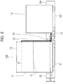
- a cooling system 100 includes a cooling tank 11 containing a coolant C, a leakage receiving portion 21 disposed between the cooling tank 11 and a floor surface, another leakage receiving portion 23 disposed between a heat exchanger 13 and an installation surface, and a passage 25 for connecting the leakage receiving portions 21 and 23.
- a plurality of electronic devices (not shown) are immersed in the coolant C that circulates in the cooling tank 11 so as to be directly cooled.
- the cooling tank 11 has an open space.
- the cooling tank 11 having the "open space" described in the specification includes the cooling tank with a simple sealing structure sufficient to secure maintainability of the electronic device.
- the simple sealing structure refers to the one that allows a top plate 12 to be openably or detachably mounted onto the opening of the cooling tank 11 via a packing or the like.
- the heat exchanger 13 is configured to cool the coolant C outside the cooling tank 11, which has been warmed as a result of taking heat from the electronic devices in the cooling tank 11.
- various types of heat exchanger such as radiator, chiller, cooling tower
- the coolant C which has been warmed and discharged from the outlet formed at the upper part of the cooling tank 11 passes through a flow passage 15, and is fed by a pump 19 under pressure toward the heat exchanger 13.
- the coolant C which is cooled by the heat exchanger 13 is introduced into an inlet (not shown) formed in the bottom of the cooling tank 11 while passing through a flow passage 17.
- the leakage receiving portion 21 may be constituted by a distribution plate for distributing the load applied from the cooling tank 11, and a closed side wall (height: h1) disposed on the distribution plate to enclose the cooling tank 11.
- the leakage receiving portion Upon leakage of the coolant C from the cooling tank 11 (including the flow path of the coolant C such as the flow passages 15 and 17 attached to the bottom or the side part of the cooling tank 11), the leakage receiving portion is configured to receive the leaked coolant L.
- the leakage receiving portion 21 may further include a lid member 22 that covers the upper opening. The lid member 22 is effective to prevent mixture of the foreign substance in the coolant L leaked from the opening, and to facilitate the access to the cooling tank 11 by closing the upper opening.
- the other leakage receiving portion 23 is disposed to receive the coolant L overflown from the leakage receiving portion 21 for accumulating the leaked coolant by the volume in excess of the predetermined volume.
- the predetermined volume may be set by adjusting the area of the distribution plate, and the height h2 from the floor surface (more correctly, the surface of the distribution plate disposed on the floor surface) to the lowermost part of the passage 25 (in the example shown in Figure 2 , the floor surface is on the same horizontal plane as the surface on which the heat exchanger 13 is disposed).
- the other leakage receiving portion 23 may also include a lid member 24 for covering the upper opening. Especially, in the case where the heat exchanger 13 is disposed outdoors, the use of the lid member 24 is essential for preventing mixture of the foreign substance.
- the passage 25 passes the overflown coolant L by the volume in excess of the predetermined volume from the leakage receiving portion 21 to the other leakage receiving portion 23.
- the leaked coolant L is kept accumulated in the leakage receiving portion 21 until the volume of the leaked coolant L reaches the predetermined volume.
- the coolant may be collected at the single location.
- the overflown coolant L in excess of the predetermined volume passes through the passage 25 so as to be accumulated in the other leakage receiving portion 23.
- the coolant has to be collected at two locations.
- the cooling system in the above-described case may be assembled by inserting the leakage receiving portion 21 with small area, which is short in height into the building. This makes it possible to significantly lessen difficulties in loading and installation works.
- the passage 25 may be made of a flexible pipe, having both ends rigidly fixed to the side wall of the leakage receiving portion 21 and the side wall of the other leakage receiving portion 23 using fasteners.
- the heat exchanger 13 is disposed on the other leakage receiving portion 23. It is possible to dispose another cooling tank (having the similar structure to that of the cooling tank 11, with which the coolant C is filled) separately from the cooling tank 11 instead of using the heat exchanger 13. In the above-described case, it is possible to accumulate the coolant L leaked from the thus provided cooling tank in the other leakage receiving portion 23 up to the predetermined volume.
- the leaked coolant L by the volume in excess of the predetermined volume passes through the passage 25 so as to be accumulated in the leakage receiving portion 21.
- the structure similar to the one as described above may be applied to the cooling system including the third or more cooling tanks in addition to the cooling tank 11 and the other cooling tank. In such a case, it is possible to dispose the third or more cooling tanks corresponding to the third or more leakage receiving portions, respectively.
- the leakage receiving portions 21, 23, the third or more leakage receiving portions may be arbitrarily combined, and connected via the passages. For example, it is possible to arrange 3 or more leakage receiving portions corresponding to the respective cooling tanks longitudinally or laterally in a row, and to connect adjacent leakage receiving portions via the passage.
- the cooling tank 11 contains the coolant C sufficient to immerse the entire bodies of the electronic devices (not shown) up to the liquid surface N in the normal state. It is preferable to use a fluorine-based inert liquid formed of the complete fluoride (perfluorocarbon compound) well known as "Fluorinert (trademark of 3M Japan Products Limited) FC-72" (boiling point: 56°C), "Fluorinert FC-770" (boiling point: 95°C), “Fluorinert FC-3283” (boiling point 128°C), “Fluorinert FC-40” (boiling point: 155°C), “Fluorinert FC-43” (boiling point: 174°C), all of which are manufactured by 3M Japan Products Limited.
- FC-72 (boiling point: 56°C)
- Fluorinert FC-770 (boiling point: 95°C)
- Fluorinert FC-43 or FC-40 as the coolant is significantly advantageous for efficiently cooling the electronic devices disposed with high density in the cooling tank 11 of a small volume, while remarkably suppressing the loss of the coolant C due to evaporation from the cooling tank 11 with the open space.
- Fluorinert FC-43 or FC-40 has the boiling point equal to or higher than 150°C, which hardly evaporates. It is possible to attach the top plate 12 onto the upper opening of the cooling tank 11 detachably or openably so as to facilitate the maintenance of the electronic device (not shown). For example, it is possible to support the top plate 12 openably using a not shown hinge attached to one edge of the upper opening of the cooling tank 11.
- FIG. 4 shows a cooling system 200 according to another embodiment of the present invention, indicating an exemplary structure having an additional leakage receiving portion disposed on the installation surface at the height lower than the floor surface on which the leakage receiving portion is disposed.
- the same components as those of the cooling system 100 will be designated with the same codes.
- the cooling system 200 according to the embodiment includes a floor surface 32 and an installation surface 31 which serve as upper and lower parts of a raised bottom in two stages.
- the leakage receiving portion 21 is disposed between the floor surface 32 and the cooling tank 11.
- An additional leakage receiving portion 33 is disposed on the installation surface 31.
- the floor surface 32 is supported with a plurality of posts 36 at the fixed height from the installation surface 31.
- the additional leakage receiving portion 33 is disposed in the space between the installation surface 31 and the floor surface 32.
- a passage 35 (which may be made of the flexible pipe) is structured to pierce through the distribution plate of the leakage receiving portion 21 and the floor surface 32, while having one end located in the leakage receiving portion 21, and the other end located in the additional leakage receiving portion 33. If the volume of the coolant L overflown from the leakage receiving portion 21 which accumulates the leaked coolant L exceeds a predetermined volume, the additional leakage receiving portion 33 is structured to receive the overflown coolant L flowing down through the passage 35.
- the predetermined volume may be set by adjusting the area of the distribution plate, and a height h4 from the floor surface (more correctly, the surface of the distribution plate disposed on the floor surface) to one end of the passage 35.
- a lid member 34 for covering the upper opening may be provided for the additional leakage receiving portion 33.
- increase in the capacity of the additional leakage receiving portion 33 positioned in the space between the installation surface 31 and the floor surface 32 may reduce the capacity of the leakage receiving portion 21. This ensures to make the area of the distribution plate smaller, or make the height h3 of the side wall lower. Accordingly, it is significantly advantageous in minimization of the capacity of the leakage receiving portion 21.
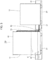
- FIG. 5 shows a cooling system 300 according to another embodiment of the present invention, which includes a leakage receiving portion 41 disposed between the cooling tank 11 and the floor surface so as to receive the coolant leaked from the cooling tank 11.
- the leakage receiving portion 41 includes a distribution plate 40 for distributing the load applied from the cooling tank 11, a closed side wall that is disposed on the distribution plate 40 to enclose the cooling tank 11, and a lid member 42 for covering the upper opening between the closed side wall and the cooling tank 11. It is the most preferable to set the capacity of the leakage receiving portion 41 sufficient to entirely receive the maximum possible volume of the coolant leaked from the cooling tank 11.
- the bottom surface of the leakage receiving portion 41 in contact with the floor surface serves as the distribution plate with wide area so that the load applied from the cooling tank 11 is distributed over the wide area. Additionally, the height of the side wall of the leakage receiving portion 41 may be kept low.
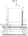
- the cooling system 400 according to the embodiment includes a cooling tank 50 containing the coolant, and the leakage receiving portion 21 disposed between the cooling tank 50 and the floor surface so as to receive the coolant leaked from the cooling tank 50.
- the cooling tank 50 includes a lower structure 53 fixed to the floor surface 32, an upper structure 51 in which the electronic devices (not shown) are immersed in the coolant C, and a seismic isolation device 55 disposed between the lower structure 53 and the upper structure 51.
- the bottom of the leakage receiving portion 21 in contact with the floor surface 32 may serve as the distribution plate for distributing the load applied from the cooling tank 50 in the similar way to the above-described embodiment.
- the leakage receiving portion 21 may be constituted by the distribution plate, the closed side wall disposed on the distribution plate to enclose the cooling tank 50, and the lid member 22 for covering the upper opening between the closed side wall and the cooling tank 50.
- the lower structure 53 includes a dispenser (not shown) for dispensing the cold coolant C.
- the upper structure 51 includes a plurality of inflow pipes 52 each allowing the dispensed cold coolant C to flow into the cooling tank 50.
- the inflow pipes 52 may be disposed separately at predetermined intervals while extending upward from the bottom of the upper structure 51 of the cooling tank 50.
- the inflow pipes 52 and the dispenser (not shown) are connected using flexible pipes 56, respectively.
- the upper structure 51 includes a plurality of outflow pipes 54 which allow outflow of the coolant C that has been warmed in the cooling tank 50.
- the lower structure 53 includes a collector (not shown) for collecting the warmed coolant C.
- the outflow pipes 54 may be disposed separately at predetermined intervals while extending upward from the bottom of the upper structure 51 of the cooling tank 50.
- Each of the outflow pipes 54 is connected to the collector using the flexible pipe 56.
- a flow passage 57 extending from the outlet formed at the upper part of the cooling tank 50 is also made of the flexible pipe.
- the dispenser (not shown) and the inflow pipes 52, and the collector (not shown) and the outflow pipes 54 may be disposed alternately in the depth direction of the cooling tank 50, respectively. This makes it possible to prevent each cooling performance from becoming different among the electronic devices housed in the cooling tank 50 with high density depending on the housed position.
- the seismic isolation device 55 disposed between the lower structure 53 and the upper structure 51 of the cooling tank 50 is configured to make the vibration of the lower structure 53 less transferable to the upper structure 51.
- the seismic isolation device 55 serves to make movement of the upper structure 51 slower relative to the lower structure 53.
- the flow passage between the lower structure 53 and the upper structure 51 is made of the flexible pipe 56 so as to effectively prevent generation of crack or fracture.
- the seismic isolation device 55 employs the isolator (laminated rubber bearing, sliding bearing, or rolling bearing) for supporting the heavy upper structure 51 of the cooling tank 50.
- the damper may be used as needed for stopping vibration of the upper structure 51 at the early stage after the earthquake settles down.
- the specific structures or functions of various kinds of isolators and dampers employed for the seismic isolation device 55 are well known to those skilled in the art, and detailed explanations thereof, thus will be omitted.
- the high density cooling system according to the embodiment as described above ensures to be highly durable against the strong impact and vibration attributing to outside causes, for example, the disaster like earthquake.
- the leaked coolant is received by the leakage receiving portion 21 so as to be temporarily accumulated. This makes it possible to facilitate collection of the leaked coolant.
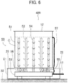
- a cooling system 500 is exemplified as another type of the high density cooling system having the seismic isolation function likewise the cooling system 400 as shown in Figure 6 .
- the same components as those of the cooling system 400 will be designated with the same codes.
- the cooling system 500 according to the embodiment includes a cooling tank 60 containing the coolant, and the leakage receiving portion 21 disposed between the cooling tank 60 and the floor surface for receiving the coolant leaked from the cooling tank 60.
- the cooling tank 60 includes a lower structure 63 fixed to the floor surface 32, an upper structure 61 in which a plurality of electronic devices (not shown) are immersed in the coolant C, and the seismic isolation device 55 disposed between the lower structure 63 and the upper structure 61.
- the bottom of the leakage receiving portion 21 in contact with the floor surface 32 may serve as the distribution plate for distributing the load applied from the cooling tank 60 likewise the above-described embodiment.
- the leakage receiving portion 21 may include the distribution plate, the closed side wall disposed on the distribution plate to enclose the cooling tank 60, and the lid member 22 for covering the upper opening between the closed side wall and the cooling tank 60.
- the lower structure 63 includes an inlet passage that passes the cold coolant C
- the upper structure 61 includes a dispenser 66 for dispensing the cold coolant C, and the plurality of inflow pipes each allowing the dispensed cold coolant C to flow into the cooling tank 60.
- the inlet passage and the dispenser 66 are connected with a flexible pipe 67.
- the flow passage 57 extending from the outlet formed at the upper part of the cooling tank 60 is also made of the flexible pipe.
- the upper structure 61 further includes the outflow pipes 54 for discharging the coolant C warmed in the cooling tank 60 with its outer part, and the collector (not shown) for collecting the warmed coolant C.
- the outflow pipes 54 may be disposed separately at predetermined intervals while extending upward from the bottom of the upper structure 61 of the cooling tank 60.
- the lower structure 63 includes the outlet passage that passes the warmed coolant C. The collector and the outlet passage are connected using the flexible pipe 67.
- cooling system 500 Advantages of the cooling system 500 according to the embodiment are similar to those of the above-described cooling system 400, and explanations thereof, thus will be omitted.
- the seismic isolation function of the cooling system 400 as shown in Figure 6 or the seismic isolation function of the cooling system 500 as shown in Figure 7 may be imparted to the cooling system 300 as shown in Figure 5 .
- Detailed explanations of structures of the modified example will be omitted as they are analogous to those of the cooling systems 400 and 500 as shown in Figures 6 and 7 , respectively.
- the electronic device may include the processor installed on the board.
- the processor may be configured to include CPU (Central Processing Unit) and/or GPU (Graphics Processing Unit).
- the electronic device may include the high-speed memory, chipset, network unit, PCI Express bus, bus switch unit, SSD (Solid State Drive), and power unit (AC-DC converter, DC-DC voltage converter).
- the electronic device may be the one for the storage unit, for example, server including the blade server, router, and SSD.
- the high density cooling system is allowed to use the electronic device with the width smaller than the usual width of the generally employed electronic device (for example, approximately 1/2, 1/3, 1/4 of the width).
- the present invention is applicable to the cooling system configured to cool the electronic devices immersed in the coolant.
- Reference Signs List
Landscapes
- Engineering & Computer Science (AREA)
- Physics & Mathematics (AREA)
- Microelectronics & Electronic Packaging (AREA)
- Thermal Sciences (AREA)
- General Engineering & Computer Science (AREA)
- Theoretical Computer Science (AREA)
- General Physics & Mathematics (AREA)
- Human Computer Interaction (AREA)
- Computer Hardware Design (AREA)
- Automation & Control Theory (AREA)
- Cooling Or The Like Of Electrical Apparatus (AREA)
- Cooling Or The Like Of Semiconductors Or Solid State Devices (AREA)
Applications Claiming Priority (1)
| Application Number | Priority Date | Filing Date | Title |
|---|---|---|---|
| PCT/JP2015/081791 WO2017081779A1 (ja) | 2015-11-11 | 2015-11-11 | 電子機器の冷却システム |
Publications (2)
| Publication Number | Publication Date |
|---|---|
| EP3376338A1 true EP3376338A1 (de) | 2018-09-19 |
| EP3376338A4 EP3376338A4 (de) | 2018-12-05 |
Family
ID=58694809
Family Applications (1)
| Application Number | Title | Priority Date | Filing Date |
|---|---|---|---|
| EP15908299.9A Withdrawn EP3376338A4 (de) | 2015-11-11 | 2015-11-11 | Kühlsystem für elektronische vorrichtung |
Country Status (5)
| Country | Link |
|---|---|
| US (1) | US20180356866A1 (de) |
| EP (1) | EP3376338A4 (de) |
| JP (1) | JP6127217B1 (de) |
| CN (1) | CN108369442A (de) |
| WO (1) | WO2017081779A1 (de) |
Families Citing this family (5)
| Publication number | Priority date | Publication date | Assignee | Title |
|---|---|---|---|---|
| WO2017081780A1 (ja) * | 2015-11-11 | 2017-05-18 | 株式会社ExaScaler | 電子機器の冷却システム |
| US11160194B2 (en) * | 2019-11-14 | 2021-10-26 | Liquidstack Holding B.V. | Hot swap condensor for immersion cooling |
| AU2020459333A1 (en) * | 2020-07-20 | 2022-05-26 | Ivan Kirillov | Fast flow cooling bath for multiprocessor circuit boards |
| US20230247795A1 (en) | 2022-01-28 | 2023-08-03 | The Research Foundation For The State University Of New York | Regenerative preheater for phase change cooling applications |
| JP2024018160A (ja) * | 2022-07-29 | 2024-02-08 | 京セラドキュメントソリューションズ株式会社 | 冷却装置、および画像形成装置 |
Family Cites Families (16)
| Publication number | Priority date | Publication date | Assignee | Title |
|---|---|---|---|---|
| US233234A (en) * | 1880-10-12 | grage | ||
| JPS6214704Y2 (de) * | 1978-07-19 | 1987-04-15 | ||
| JPS596849U (ja) * | 1982-07-05 | 1984-01-17 | 富士電機株式会社 | 水冷式半導体変換装置 |
| JPH02124415U (de) * | 1989-03-20 | 1990-10-12 | ||
| US20090178727A1 (en) * | 2008-01-14 | 2009-07-16 | Murphy Stephen A | Combination water conservation apparatus and watering bucket with method of use |
| US10123463B2 (en) * | 2008-08-11 | 2018-11-06 | Green Revolution Cooling, Inc. | Liquid submerged, horizontal computer server rack and systems and method of cooling such a server rack |
| US7983040B2 (en) * | 2008-10-23 | 2011-07-19 | International Business Machines Corporation | Apparatus and method for facilitating pumped immersion-cooling of an electronic subsystem |
| JP2010172640A (ja) * | 2009-02-02 | 2010-08-12 | Panasonic Corp | ドラム式洗濯機 |
| US10054754B2 (en) * | 2009-02-04 | 2018-08-21 | Nikon Corporation | Thermal regulation of vibration-sensitive objects with conduit circuit having liquid metal, pump, and heat exchanger |
| CN201726300U (zh) * | 2010-07-12 | 2011-01-26 | 四川英杰电气有限公司 | 一种用于igbt逆变电源中防止冷却漏水的装置 |
| US8619425B2 (en) * | 2011-10-26 | 2013-12-31 | International Business Machines Corporation | Multi-fluid, two-phase immersion-cooling of electronic component(s) |
| JP6127416B2 (ja) * | 2012-09-07 | 2017-05-17 | 富士通株式会社 | 電子機器 |
| US9504190B2 (en) * | 2013-05-06 | 2016-11-22 | Green Revolution Cooling, Inc. | System and method of packaging computing resources for space and fire-resistance |
| JP2015078745A (ja) * | 2013-10-17 | 2015-04-23 | 株式会社ケイズベルテック | 免震機能を備えた受け台 |
| CN103593018A (zh) * | 2013-11-13 | 2014-02-19 | 曙光信息产业(北京)有限公司 | 用于服务器系统的电气转接装置和服务器 |
| CN104284536B (zh) * | 2014-10-28 | 2017-06-06 | 深圳绿色云图科技有限公司 | 服务器机柜及具有其的机柜组和液体浸没冷却服务器系统 |
-
2015
- 2015-11-11 JP JP2016546555A patent/JP6127217B1/ja active Active
- 2015-11-11 EP EP15908299.9A patent/EP3376338A4/de not_active Withdrawn
- 2015-11-11 US US15/773,128 patent/US20180356866A1/en not_active Abandoned
- 2015-11-11 WO PCT/JP2015/081791 patent/WO2017081779A1/ja not_active Ceased
- 2015-11-11 CN CN201580084495.3A patent/CN108369442A/zh active Pending
Also Published As
| Publication number | Publication date |
|---|---|
| CN108369442A (zh) | 2018-08-03 |
| JPWO2017081779A1 (ja) | 2017-11-09 |
| JP6127217B1 (ja) | 2017-05-10 |
| WO2017081779A1 (ja) | 2017-05-18 |
| EP3376338A4 (de) | 2018-12-05 |
| US20180356866A1 (en) | 2018-12-13 |
Similar Documents
| Publication | Publication Date | Title |
|---|---|---|
| EP3376339A1 (de) | Kühlsystem für elektronische vorrichtung | |
| US20200370845A1 (en) | Cooling system for electronic device | |
| EP3376338A1 (de) | Kühlsystem für elektronische vorrichtung | |
| CN107924896B (zh) | 电子设备的冷却系统 | |
| JP6078054B2 (ja) | 高さが減少した熱伝達装置 | |
| US20180070477A1 (en) | Electronic-device cooling system | |
| US20180153058A1 (en) | Cooling system and method of cooling electronic device | |
| US8305754B2 (en) | Heat dissipation structure of electronic device | |
| US20190338962A1 (en) | A heating system and a heating method | |
| US20170354061A1 (en) | Electronic apparatus cooling system | |
| EP2802197A1 (de) | Elektronische vorrichtung sowie wärmestrahlungssystem und wärmestrahlungsverfahren dafür | |
| US20110315344A1 (en) | Interleaved, immersion-cooling apparatus and method for an electronic subsystem of an electronics rack | |
| US12324131B2 (en) | Manifold systems, devices, and methods for thermal management of hardware components | |
| WO2014132085A1 (en) | A module for cooling one or more heat generating components | |
| Moon et al. | Effect of integrated copper pad on the performance of boiling-driven wickless thermal ground plane | |
| CN106461348A (zh) | 具有用于抑制液体运动的通道的换热器 | |
| EP3451120A1 (de) | Kühlsystem | |
| WO2023278040A1 (en) | Hybrid motherboard cooling system for air-cooled servers | |
| RU2731439C2 (ru) | Система охлаждения электронной системы | |
| KR102369698B1 (ko) | 핵연료 저장조의 냉각액을 냉각시키기 위한 냉각 소자, 해당 시스템, 핵연료 저장조 및 핵 시설 | |
| CN121726589A (zh) | 电池箱及用电设备 | |
| US8622043B1 (en) | Electrical power generation system that includes a fluid containment system |
Legal Events
| Date | Code | Title | Description |
|---|---|---|---|
| PUAI | Public reference made under article 153(3) epc to a published international application that has entered the european phase |
Free format text: ORIGINAL CODE: 0009012 |
|
| 17P | Request for examination filed |
Effective date: 20180607 |
|
| AK | Designated contracting states |
Kind code of ref document: A1 Designated state(s): AL AT BE BG CH CY CZ DE DK EE ES FI FR GB GR HR HU IE IS IT LI LT LU LV MC MK MT NL NO PL PT RO RS SE SI SK SM TR |
|
| AX | Request for extension of the european patent |
Extension state: BA ME |
|
| A4 | Supplementary search report drawn up and despatched |
Effective date: 20181106 |
|
| RIC1 | Information provided on ipc code assigned before grant |
Ipc: H05K 7/20 20060101ALI20181029BHEP Ipc: G06F 1/20 20060101AFI20181029BHEP |
|
| DAV | Request for validation of the european patent (deleted) | ||
| DAX | Request for extension of the european patent (deleted) | ||
| STAA | Information on the status of an ep patent application or granted ep patent |
Free format text: STATUS: THE APPLICATION IS DEEMED TO BE WITHDRAWN |
|
| 18D | Application deemed to be withdrawn |
Effective date: 20190604 |