EP3376511B1 - Procédé de fabrication de corps formé de poudre comprimée - Google Patents
Procédé de fabrication de corps formé de poudre comprimée Download PDFInfo
- Publication number
- EP3376511B1 EP3376511B1 EP16863991.2A EP16863991A EP3376511B1 EP 3376511 B1 EP3376511 B1 EP 3376511B1 EP 16863991 A EP16863991 A EP 16863991A EP 3376511 B1 EP3376511 B1 EP 3376511B1
- Authority
- EP
- European Patent Office
- Prior art keywords
- compact
- iron
- volume
- less
- loss
- Prior art date
- Legal status (The legal status is an assumption and is not a legal conclusion. Google has not performed a legal analysis and makes no representation as to the accuracy of the status listed.)
- Active
Links
Images
Classifications
-
- H—ELECTRICITY
- H01—ELECTRIC ELEMENTS
- H01F—MAGNETS; INDUCTANCES; TRANSFORMERS; SELECTION OF MATERIALS FOR THEIR MAGNETIC PROPERTIES
- H01F1/00—Magnets or magnetic bodies characterised by the magnetic materials therefor; Selection of materials for their magnetic properties
- H01F1/01—Magnets or magnetic bodies characterised by the magnetic materials therefor; Selection of materials for their magnetic properties of inorganic materials
- H01F1/03—Magnets or magnetic bodies characterised by the magnetic materials therefor; Selection of materials for their magnetic properties of inorganic materials characterised by their coercivity
- H01F1/12—Magnets or magnetic bodies characterised by the magnetic materials therefor; Selection of materials for their magnetic properties of inorganic materials characterised by their coercivity of soft-magnetic materials
- H01F1/14—Magnets or magnetic bodies characterised by the magnetic materials therefor; Selection of materials for their magnetic properties of inorganic materials characterised by their coercivity of soft-magnetic materials metals or alloys
- H01F1/20—Magnets or magnetic bodies characterised by the magnetic materials therefor; Selection of materials for their magnetic properties of inorganic materials characterised by their coercivity of soft-magnetic materials metals or alloys in the form of particles, e.g. powder
- H01F1/22—Magnets or magnetic bodies characterised by the magnetic materials therefor; Selection of materials for their magnetic properties of inorganic materials characterised by their coercivity of soft-magnetic materials metals or alloys in the form of particles, e.g. powder pressed, sintered, or bound together
- H01F1/24—Magnets or magnetic bodies characterised by the magnetic materials therefor; Selection of materials for their magnetic properties of inorganic materials characterised by their coercivity of soft-magnetic materials metals or alloys in the form of particles, e.g. powder pressed, sintered, or bound together the particles being insulated
-
- B—PERFORMING OPERATIONS; TRANSPORTING
- B22—CASTING; POWDER METALLURGY
- B22F—WORKING METALLIC POWDER; MANUFACTURE OF ARTICLES FROM METALLIC POWDER; MAKING METALLIC POWDER; APPARATUS OR DEVICES SPECIALLY ADAPTED FOR METALLIC POWDER
- B22F1/00—Metallic powder; Treatment of metallic powder, e.g. to facilitate working or to improve properties
- B22F1/10—Metallic powder containing lubricating or binding agents; Metallic powder containing organic material
-
- B—PERFORMING OPERATIONS; TRANSPORTING
- B22—CASTING; POWDER METALLURGY
- B22F—WORKING METALLIC POWDER; MANUFACTURE OF ARTICLES FROM METALLIC POWDER; MAKING METALLIC POWDER; APPARATUS OR DEVICES SPECIALLY ADAPTED FOR METALLIC POWDER
- B22F3/00—Manufacture of workpieces or articles from metallic powder characterised by the manner of compacting or sintering; Apparatus specially adapted therefor ; Presses and furnaces
- B22F3/02—Compacting only
-
- B—PERFORMING OPERATIONS; TRANSPORTING
- B22—CASTING; POWDER METALLURGY
- B22F—WORKING METALLIC POWDER; MANUFACTURE OF ARTICLES FROM METALLIC POWDER; MAKING METALLIC POWDER; APPARATUS OR DEVICES SPECIALLY ADAPTED FOR METALLIC POWDER
- B22F3/00—Manufacture of workpieces or articles from metallic powder characterised by the manner of compacting or sintering; Apparatus specially adapted therefor ; Presses and furnaces
- B22F3/24—After-treatment of workpieces or articles
-
- H—ELECTRICITY
- H01—ELECTRIC ELEMENTS
- H01F—MAGNETS; INDUCTANCES; TRANSFORMERS; SELECTION OF MATERIALS FOR THEIR MAGNETIC PROPERTIES
- H01F1/00—Magnets or magnetic bodies characterised by the magnetic materials therefor; Selection of materials for their magnetic properties
- H01F1/01—Magnets or magnetic bodies characterised by the magnetic materials therefor; Selection of materials for their magnetic properties of inorganic materials
- H01F1/03—Magnets or magnetic bodies characterised by the magnetic materials therefor; Selection of materials for their magnetic properties of inorganic materials characterised by their coercivity
- H01F1/12—Magnets or magnetic bodies characterised by the magnetic materials therefor; Selection of materials for their magnetic properties of inorganic materials characterised by their coercivity of soft-magnetic materials
- H01F1/33—Magnets or magnetic bodies characterised by the magnetic materials therefor; Selection of materials for their magnetic properties of inorganic materials characterised by their coercivity of soft-magnetic materials mixtures of metallic and non-metallic particles; metallic particles having oxide skin
-
- H—ELECTRICITY
- H01—ELECTRIC ELEMENTS
- H01F—MAGNETS; INDUCTANCES; TRANSFORMERS; SELECTION OF MATERIALS FOR THEIR MAGNETIC PROPERTIES
- H01F1/00—Magnets or magnetic bodies characterised by the magnetic materials therefor; Selection of materials for their magnetic properties
- H01F1/01—Magnets or magnetic bodies characterised by the magnetic materials therefor; Selection of materials for their magnetic properties of inorganic materials
- H01F1/03—Magnets or magnetic bodies characterised by the magnetic materials therefor; Selection of materials for their magnetic properties of inorganic materials characterised by their coercivity
- H01F1/12—Magnets or magnetic bodies characterised by the magnetic materials therefor; Selection of materials for their magnetic properties of inorganic materials characterised by their coercivity of soft-magnetic materials
- H01F1/34—Magnets or magnetic bodies characterised by the magnetic materials therefor; Selection of materials for their magnetic properties of inorganic materials characterised by their coercivity of soft-magnetic materials non-metallic substances, e.g. ferrites
- H01F1/342—Oxides
- H01F1/344—Ferrites, e.g. having a cubic spinel structure (X2+O)(Y23+O3), e.g. magnetite Fe3O4
-
- H—ELECTRICITY
- H01—ELECTRIC ELEMENTS
- H01F—MAGNETS; INDUCTANCES; TRANSFORMERS; SELECTION OF MATERIALS FOR THEIR MAGNETIC PROPERTIES
- H01F27/00—Details of transformers or inductances, in general
- H01F27/24—Magnetic cores
- H01F27/255—Magnetic cores made from particles
-
- H—ELECTRICITY
- H01—ELECTRIC ELEMENTS
- H01F—MAGNETS; INDUCTANCES; TRANSFORMERS; SELECTION OF MATERIALS FOR THEIR MAGNETIC PROPERTIES
- H01F27/00—Details of transformers or inductances, in general
- H01F27/28—Coils; Windings; Conductive connections
-
- H—ELECTRICITY
- H01—ELECTRIC ELEMENTS
- H01F—MAGNETS; INDUCTANCES; TRANSFORMERS; SELECTION OF MATERIALS FOR THEIR MAGNETIC PROPERTIES
- H01F3/00—Cores, Yokes, or armatures
- H01F3/08—Cores, Yokes, or armatures made from powder
-
- H—ELECTRICITY
- H01—ELECTRIC ELEMENTS
- H01F—MAGNETS; INDUCTANCES; TRANSFORMERS; SELECTION OF MATERIALS FOR THEIR MAGNETIC PROPERTIES
- H01F3/00—Cores, Yokes, or armatures
- H01F3/10—Composite arrangements of magnetic circuits
-
- H—ELECTRICITY
- H01—ELECTRIC ELEMENTS
- H01F—MAGNETS; INDUCTANCES; TRANSFORMERS; SELECTION OF MATERIALS FOR THEIR MAGNETIC PROPERTIES
- H01F41/00—Apparatus or processes specially adapted for manufacturing or assembling magnets, inductances or transformers; Apparatus or processes specially adapted for manufacturing materials characterised by their magnetic properties
- H01F41/02—Apparatus or processes specially adapted for manufacturing or assembling magnets, inductances or transformers; Apparatus or processes specially adapted for manufacturing materials characterised by their magnetic properties for manufacturing cores, coils, or magnets
-
- H—ELECTRICITY
- H01—ELECTRIC ELEMENTS
- H01F—MAGNETS; INDUCTANCES; TRANSFORMERS; SELECTION OF MATERIALS FOR THEIR MAGNETIC PROPERTIES
- H01F41/00—Apparatus or processes specially adapted for manufacturing or assembling magnets, inductances or transformers; Apparatus or processes specially adapted for manufacturing materials characterised by their magnetic properties
- H01F41/02—Apparatus or processes specially adapted for manufacturing or assembling magnets, inductances or transformers; Apparatus or processes specially adapted for manufacturing materials characterised by their magnetic properties for manufacturing cores, coils, or magnets
- H01F41/0206—Manufacturing of magnetic cores by mechanical means
- H01F41/0246—Manufacturing of magnetic circuits by moulding or by pressing powder
-
- B—PERFORMING OPERATIONS; TRANSPORTING
- B22—CASTING; POWDER METALLURGY
- B22F—WORKING METALLIC POWDER; MANUFACTURE OF ARTICLES FROM METALLIC POWDER; MAKING METALLIC POWDER; APPARATUS OR DEVICES SPECIALLY ADAPTED FOR METALLIC POWDER
- B22F1/00—Metallic powder; Treatment of metallic powder, e.g. to facilitate working or to improve properties
- B22F1/10—Metallic powder containing lubricating or binding agents; Metallic powder containing organic material
- B22F1/102—Metallic powder coated with organic material
-
- B—PERFORMING OPERATIONS; TRANSPORTING
- B22—CASTING; POWDER METALLURGY
- B22F—WORKING METALLIC POWDER; MANUFACTURE OF ARTICLES FROM METALLIC POWDER; MAKING METALLIC POWDER; APPARATUS OR DEVICES SPECIALLY ADAPTED FOR METALLIC POWDER
- B22F1/00—Metallic powder; Treatment of metallic powder, e.g. to facilitate working or to improve properties
- B22F1/16—Metallic particles coated with a non-metal
-
- B—PERFORMING OPERATIONS; TRANSPORTING
- B22—CASTING; POWDER METALLURGY
- B22F—WORKING METALLIC POWDER; MANUFACTURE OF ARTICLES FROM METALLIC POWDER; MAKING METALLIC POWDER; APPARATUS OR DEVICES SPECIALLY ADAPTED FOR METALLIC POWDER
- B22F3/00—Manufacture of workpieces or articles from metallic powder characterised by the manner of compacting or sintering; Apparatus specially adapted therefor ; Presses and furnaces
- B22F3/02—Compacting only
- B22F2003/023—Lubricant mixed with the metal powder
-
- B—PERFORMING OPERATIONS; TRANSPORTING
- B22—CASTING; POWDER METALLURGY
- B22F—WORKING METALLIC POWDER; MANUFACTURE OF ARTICLES FROM METALLIC POWDER; MAKING METALLIC POWDER; APPARATUS OR DEVICES SPECIALLY ADAPTED FOR METALLIC POWDER
- B22F3/00—Manufacture of workpieces or articles from metallic powder characterised by the manner of compacting or sintering; Apparatus specially adapted therefor ; Presses and furnaces
- B22F3/24—After-treatment of workpieces or articles
- B22F2003/248—Thermal after-treatment
-
- B—PERFORMING OPERATIONS; TRANSPORTING
- B22—CASTING; POWDER METALLURGY
- B22F—WORKING METALLIC POWDER; MANUFACTURE OF ARTICLES FROM METALLIC POWDER; MAKING METALLIC POWDER; APPARATUS OR DEVICES SPECIALLY ADAPTED FOR METALLIC POWDER
- B22F2201/00—Treatment under specific atmosphere
- B22F2201/03—Oxygen
-
- B—PERFORMING OPERATIONS; TRANSPORTING
- B22—CASTING; POWDER METALLURGY
- B22F—WORKING METALLIC POWDER; MANUFACTURE OF ARTICLES FROM METALLIC POWDER; MAKING METALLIC POWDER; APPARATUS OR DEVICES SPECIALLY ADAPTED FOR METALLIC POWDER
- B22F2201/00—Treatment under specific atmosphere
- B22F2201/50—Treatment under specific atmosphere air
-
- B—PERFORMING OPERATIONS; TRANSPORTING
- B22—CASTING; POWDER METALLURGY
- B22F—WORKING METALLIC POWDER; MANUFACTURE OF ARTICLES FROM METALLIC POWDER; MAKING METALLIC POWDER; APPARATUS OR DEVICES SPECIALLY ADAPTED FOR METALLIC POWDER
- B22F2301/00—Metallic composition of the powder or its coating
- B22F2301/35—Iron
-
- B—PERFORMING OPERATIONS; TRANSPORTING
- B22—CASTING; POWDER METALLURGY
- B22F—WORKING METALLIC POWDER; MANUFACTURE OF ARTICLES FROM METALLIC POWDER; MAKING METALLIC POWDER; APPARATUS OR DEVICES SPECIALLY ADAPTED FOR METALLIC POWDER
- B22F2302/00—Metal Compound, non-Metallic compound or non-metal composition of the powder or its coating
- B22F2302/25—Oxide
-
- B—PERFORMING OPERATIONS; TRANSPORTING
- B22—CASTING; POWDER METALLURGY
- B22F—WORKING METALLIC POWDER; MANUFACTURE OF ARTICLES FROM METALLIC POWDER; MAKING METALLIC POWDER; APPARATUS OR DEVICES SPECIALLY ADAPTED FOR METALLIC POWDER
- B22F2998/00—Supplementary information concerning processes or compositions relating to powder metallurgy
- B22F2998/10—Processes characterised by the sequence of their steps
-
- B—PERFORMING OPERATIONS; TRANSPORTING
- B22—CASTING; POWDER METALLURGY
- B22F—WORKING METALLIC POWDER; MANUFACTURE OF ARTICLES FROM METALLIC POWDER; MAKING METALLIC POWDER; APPARATUS OR DEVICES SPECIALLY ADAPTED FOR METALLIC POWDER
- B22F2999/00—Aspects linked to processes or compositions used in powder metallurgy
-
- B—PERFORMING OPERATIONS; TRANSPORTING
- B22—CASTING; POWDER METALLURGY
- B22F—WORKING METALLIC POWDER; MANUFACTURE OF ARTICLES FROM METALLIC POWDER; MAKING METALLIC POWDER; APPARATUS OR DEVICES SPECIALLY ADAPTED FOR METALLIC POWDER
- B22F3/00—Manufacture of workpieces or articles from metallic powder characterised by the manner of compacting or sintering; Apparatus specially adapted therefor ; Presses and furnaces
- B22F3/10—Sintering only
- B22F3/1017—Multiple heating or additional steps
- B22F3/1021—Removal of binder or filler
-
- C—CHEMISTRY; METALLURGY
- C22—METALLURGY; FERROUS OR NON-FERROUS ALLOYS; TREATMENT OF ALLOYS OR NON-FERROUS METALS
- C22C—ALLOYS
- C22C2202/00—Physical properties
- C22C2202/02—Magnetic
-
- C—CHEMISTRY; METALLURGY
- C22—METALLURGY; FERROUS OR NON-FERROUS ALLOYS; TREATMENT OF ALLOYS OR NON-FERROUS METALS
- C22C—ALLOYS
- C22C33/00—Making ferrous alloys
- C22C33/02—Making ferrous alloys by powder metallurgy
-
- H—ELECTRICITY
- H01—ELECTRIC ELEMENTS
- H01F—MAGNETS; INDUCTANCES; TRANSFORMERS; SELECTION OF MATERIALS FOR THEIR MAGNETIC PROPERTIES
- H01F3/00—Cores, Yokes, or armatures
- H01F3/10—Composite arrangements of magnetic circuits
- H01F2003/106—Magnetic circuits using combinations of different magnetic materials
-
- H—ELECTRICITY
- H01—ELECTRIC ELEMENTS
- H01F—MAGNETS; INDUCTANCES; TRANSFORMERS; SELECTION OF MATERIALS FOR THEIR MAGNETIC PROPERTIES
- H01F37/00—Fixed inductances not covered by group H01F17/00
Definitions
- the present disclosure relates to a compact, an electromagnetic component, and a method for producing a compact.
- One of magnetic cores for electromagnetic components and so forth is a compact in which a soft-magnetic powder is compacted into a predetermined shape (for example, PTL 1).
- PTL2 discloses a method of producing a magnetic core according to the preamble of appended claim 1.
- a compact according to the present disclosure includes coated soft-magnetic particles collected, the coated soft-magnetic particles including iron-based particles and insulating coatings that cover surfaces of the iron-based particles.
- a magnetic path cross section has a cross-sectional perimeter of more than 20 mm.
- At least part of a surface of the compact is covered with an iron-based oxide film having an average thickness of 0.5 ⁇ m or more and 10.0 ⁇ m or less. Letting the proportion of the surface area of the compact to the volume of the compact be surface area/volume, the content of Fe 3 O 4 present in the iron-based oxide film with respect to 100% by volume of the compact satisfies any one of (1) to (3):
- a method for producing a compact includes the steps of compacting a raw-material powder including a coated soft-magnetic powder and a lubricant to form a green compact, the coated soft-magnetic powder including iron-based particles and insulating coatings that cover surfaces of the iron-based particles; and heat-treating the green compact to form a compact in which when the compact is used for a magnetic core, a magnetic path cross section has a cross-sectional perimeter of more than 20 mm.
- the lubricant contains a component having a decomposition onset temperature of 170°C or higher, and the content of the lubricant is 0.10% or more by mass and 0.60% or less by mass based on 100% by mass of the raw-material powder.
- Conditions of the heat treatment include an oxygen concentration in an atmosphere of 0.01% or more by volume and 0.5 % or less by volume and a temperature of higher than 520°C and 700°C or lower.
- PTL 1 discloses that a raw-material powder including a coated iron powder having insulating coatings and a lubricant is compacted, the resulting green compact is heat-treated in a nitrogen atmosphere, and a slide-contact surface of the green compact with a die set is subjected to acid treatment to provide a low-loss compact having, in particular, reduced eddy-current loss and thus low iron loss, which is the sum of hysteresis loss and eddy-current loss.
- the heat treatment after the compacting contributes to a reduction in hysteresis loss.
- the use of the coated powder as a raw-material powder together with the use of the lubricant contributes to a reduction in eddy-current loss.
- an electrically conductive portion which is formed by the plastic deformation of the metal powder particles at the time of removal from the die set, between the metal powder particles formed on the slide-contact surface with the dies, is cut off by the acid treatment in which immersion in concentrated hydrochloric acid is performed, thereby further reducing eddy-current loss and iron loss.
- the acid treatment is needed in addition to the heat treatment, the number of steps is large; thus, it is desirable to improve the productivity. If masking treatment or the like is performed before the acid treatment in order to subject only a specific portion of the compact to the acid treatment without damaging a good insulating coating, the number of steps is further increased. If the acid treatment is omitted, it is difficult to sufficiently reduce the eddy-current loss, as described in test examples below.
- the eddy-current loss can be reduced, compared with the case where heat treatment after compressing is performed in a nitrogen atmosphere and where no acid treatment is performed after the heat treatment (hereinafter, also referred to as a "case of nitrogen treatment only”), as described in the test examples below.
- the iron loss in the case of air treatment is higher than the iron loss in the case of performing the acid treatment after the heat treatment in the nitrogen atmosphere (hereinafter, the case of performing both of the nitrogen treatment and the acid treatment is also referred to as a "case of nitrogen treatment + acid treatment").
- the compact desirably has low iron loss without performing acid treatment or the like after the heat treatment of the compact, specifically has iron loss lower than the case of nitrogen treatment only, preferably has iron loss lower than the case of air treatment, more preferably has iron loss comparable to, even more preferably lower than the case of nitrogen treatment + acid treatment.
- a compact according to the present disclosure includes coated soft-magnetic particles collected, the coated soft-magnetic particles including iron-based particles and insulating coatings that cover surfaces of the iron-based particles.
- a magnetic path cross section has a cross-sectional perimeter of more than 20 mm.
- At least part of a surface of the compact is covered with an iron-based oxide film having an average thickness of 0.5 ⁇ m or more and 10.0 ⁇ m or less. Letting the proportion of the surface area of the compact to the volume of the compact be surface area/volume, the content of Fe 3 O 4 present in the iron-based oxide film with respect to 100% by volume of the compact satisfies any one of (1) to (3):
- the compact When the compact is used for a magnetic core of an electromagnetic component, the compact can provide a low-loss magnetic core having iron loss lower than the case of nitrogen treatment only, preferably iron loss lower than the case of air treatment, more preferably iron loss comparable to, even more preferably lower than the case of nitrogen treatment + acid treatment, for reasons described below.
- the compact can be produced by, for example, compacting a raw-material powder mainly formed of a coated powder including iron-based particles having insulating coatings on surfaces thereof and then subjecting the resulting green compact to heat treatment under specific conditions (see a method for producing a compact described below). Acid treatment after the heat treatment can be omitted; thus, the compact also has good productivity.
- the magnetic path cross section of the compact has a cross-sectional perimeter of more than 20 mm; thus, the size of the compact is such that a relatively long eddy-current loop depending on the cross-sectional perimeter is easily formed.
- the compact is liable to have high eddy-current loss because of its size; however, in the compact, the iron-based particles are electrically insulated mainly by the insulating coatings.
- the iron-based particles that form at least part of a surface of the compact, in particular, at least part of a slide-contact surface, on which an electrically conductive portion is liable to be formed at the time of removal from the die set, with the die set are electrically insulated from each other by the iron-based oxide film having higher electrical insulation than the iron-based particles.
- the surface insulation of the compact is increased by the insulating coatings and the iron-based oxide film.
- the compact has a low content of Fe 3 O 4 , which has a sufficiently higher resistivity than the iron-based particles and which has a relatively low resistivity as an insulating material.
- the content of Fe 3 O 4 satisfies a specific range, depending on the surface area/volume.
- comparisons between compacts having the same size and density indicate that the compact basically has a lower content of Fe 3 O 4 than the case of air treatment, preferably has a lower content of Fe 3 O 4 than the case of nitrogen treatment + acid treatment, depending on production conditions.
- the compact can have reduced eddy-current loss.
- the compact Even in the case where the compact contains Fe 3 O 4 , which is a ferromagnetic material and has a higher coercive force than pure iron, in the iron-based oxide film, the content thereof is within a specific range and tends to be lower than the case of an air atmosphere.
- the compact can inhibit an increase in hysteresis loss due to the presence of Fe 3 O 4 and can have hysteresis loss comparable to or lower than the case of air treatment.
- a smaller (surface area/volume) results in a lower content of Fe 3 O 4 in the compact.
- an increase in hysteresis loss due to the presence of an excess of Fe 3 O 4 on the surface of the compact is inhibited.
- the compact according to an embodiment has a cross-sectional perimeter of 40 mm or more and a (surface area/volume) of 0.60 mm -1 or less.
- the compact according to the embodiment has a size that is liable to lead to a longer eddy-current loop, depending on the cross-sectional perimeter, a low-loss magnetic core can be formed because of a specific amount of Fe 3 O 4 in addition to good insulation resulting from the insulating coatings and the iron-based oxide film as described above.
- the compact according to an embodiment has surfaces entirely covered with the iron-based oxide film having a thickness of 0.5 ⁇ m or more and 10.0 ⁇ m or less at any point.
- the compact according to the embodiment has only small variations in the thickness of the iron-based oxide film.
- the iron-based oxide film is uniformly present on the surfaces of the compact and satisfactorily insulates the iron-based particles, which form the surfaces of the compact, from each other.
- the compact according to the embodiment has higher surface insulation, so that the eddy-current loss is easily reduced.
- an increase in hysteresis loss due to the local presence of a thick portion can be inhibited, thereby resulting in a magnetic core having lower loss.
- masking treatment or the like for the formation of the iron-based oxide film on only a specific portion is not required, thus resulting in better productivity.
- the compact according to an embodiment has a relative density of 90.0% or more and 99.0% or less.
- the compact according to the embodiment has a high density and only a few pores.
- the green compact in the production process also has a high density.
- An excess of the iron-based oxide film is less likely to be formed during the heat treatment. Fe 3 O 4 can thus be appropriately contained.
- the compact according to this embodiment because the density is not excessively high, there is no need for the application of a very high compaction pressure during the production process, thus easily preventing damage due to an excessive compaction pressure and providing a good insulating coating. Therefore, the compact according to this embodiment can provide a magnetic core having lower loss.
- An electromagnetic component according to the present disclosure includes a coil and a magnetic core on which the coil is arranged, in which at least part of the magnetic core includes any one of the compacts described above.
- the electromagnetic component is low loss because at least part, preferably the whole of the magnetic core is formed of the compact. Because the compact has good productivity, the electromagnetic component also has good productivity.
- a method for producing a compact according to the present disclosure includes a compaction step and a heat-treatment step as described below.
- Compaction step A step of compacting a raw-material powder that includes a coated soft-magnetic powder and a lubricant to form a green compact, the coated soft-magnetic powder including iron-based particles and insulating coatings that cover surfaces of the iron-based particles.
- Heat-treatment step A step of heat-treating the green compact to form a compact in which when the compact is used for a magnetic core, a magnetic path cross section has a cross-sectional perimeter of more than 20 mm.
- the lubricant contains a component having a decomposition onset temperature of 170°C or higher, and the content of the lubricant is 0.10% or more by mass and 0.60% or less by mass based on 100% by mass of the raw-material powder.
- Conditions of the heat treatment include an oxygen concentration in an atmosphere of 0.01% or more by volume and 0.5 % or less by volume and a temperature of higher than 520°C and 700°C or lower.
- the low-loss compact can be produced without performing post-treatment, such as acid treatment, after the heat treatment.
- the reasons for this are as follows: Because the coated soft-magnetic powder is used, a compact in which the insulating coatings are interposed between the iron-based particles is formed. Because a specific lubricant is used, damage to the insulating coatings due to the rubbing of the coated powder particles against each other during compacting or the like is easily prevented. Because the heat treatment temperature is not excessively high, thermal damage to the insulating coatings can be inhibited. Because the heat treatment of the green compact is performed at a specific temperature in a specific low-oxygen atmosphere, Fe in the iron-based particles included in the green compact is bonded to oxygen in the atmosphere to form an iron-based oxide, thereby producing the compact in which at least part of a surface of the green compact is covered with the iron-based oxide film.
- the iron-based oxide film is also interposed between the iron-based particles located at a portion of the green compact where the insulating coatings are peeled to expose the iron-based particles, typically at least part of a slide-contact surface of the green compact with the die set, thereby insulating the iron-based particles from each other. Because the heat treatment is performed under the specific conditions, Fe 3 O 4 , which has a relatively low resistivity, is not excessively formed as described above, and the content can be in the specific range (see the foregoing compact). From these points, the compact having good insulation is formed.
- the reasons for this are as follows: Because the oxygen concentration in the low-oxygen atmosphere is in the specific range, Fe 3 O 4 , which is a ferromagnetic material, is not excessively formed. Thus, the content of Fe 3 O 4 can be in the specific range as described above. Because the heat-treatment temperature is relatively high, thermal damage to the insulating coatings can be prevented while strain introduced into the iron-based particles during the compaction step can be sufficiently removed.
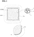
- FIG. 1 is a cross-sectional view taken along cutting plane line (I)-(I) of Figure 2 (plane orthogonal to magnetic flux).
- the compact 10 is mainly formed of a soft-magnetic powder and is produced by compacting a raw-material powder mainly formed of the soft-magnetic powder into a predetermined shape and then performing heat treatment.
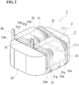
- the compact 10 is used for at least part of a magnetic core 3 included in an electromagnetic component 1 as illustrated in Figure 2 to form a magnetic path.
- Figure 2 illustrates the case where the compacts 10 (core pieces 31m and 32) are combined together to form a ring-shaped closed magnetic circuit.
- the compact 10 can have various shapes (see Section Electromagnetic Component described below).
- the compact 10 of the embodiment is formed of coated soft-magnetic particles collected, the coated soft-magnetic particles including iron-based particles 7 and insulating coatings 8 that cover surfaces of the iron-based particles 7.
- the cross-sectional perimeter L of a magnetic path cross section S 10 (hatched area in Figure 1 ) is relatively long.
- the compact 10 of the embodiment includes an iron-based oxide film 13 having a specific thickness, the iron-based oxide film 13 serving as a coating layer that covers at least part of its surface.
- the content of a specific component (Fe 3 O 4 ) in the iron-based oxide film 13 is in a specific range.
- the size of the compact 10 is such that the cross-sectional perimeter L is relatively long; however, because the compact 10 includes the insulating coatings and the iron-based oxide film 13 and has a low content of Fe 3 O 4 , the low-loss magnetic core 3 can be formed.
- the compact 10 will be described in more detail below.
- the iron-based particles 7 included in coated soft-magnetic particles 9 are composed of an iron-based material mainly containing Fe.
- the iron-based material include pure iron (having a purity of 99% or more by mass, the balance being incidental impurities), and iron-based alloys having an Fe content of more than 50% by mass.
- the iron-based alloys include Fe-Si-Al-based alloys, Fe-Si-based alloys, and Fe-Al-based alloys.
- the pure iron is preferred for the following reasons:
- the pure iron has high magnetic permeability and high magnetic flux density.
- the pure iron has good plastic deformability, so that the density and strength of the compact 10 are easily increased. Because of its high purity, the hysteresis loss can be reduced.
- the insulating coatings 8 included in the coated soft-magnetic particles 9 are interposed between the iron-based particles 7 to increase the insulation, contributing to a reduction in eddy-current loss. Examples of the insulating material of the insulating coatings 8 are described below.
- the insulating coatings 8 may have a single-layer structure or a multilayer structure including different insulating materials.
- a metal phosphate compound such as iron phosphate has good adhesion to iron and good deformability and follows the deformation of the iron-based particles 7 to deform during compacting; thus, the metal phosphate compound is not easily damaged. Accordingly, the compact 10 has the good insulating coatings 8; thus, an eddy current is easily reduced.
- the insulating coatings 8 have an average thickness of, for example, 10 nm or more and 1 ⁇ m or less. An average thickness of 10 nm or more results in good insulation between the iron-based particles 7. An average thickness of 1 ⁇ m or less does not result in an excessive amount of the insulating coatings 8 to inhibit a decrease in the percentage of a magnetic component in the compact 10 due to an excess of the insulating coatings 8, thereby providing desired magnetic properties.
- the lower limit of the thickness (the total thickness in the case of the multilayer structure) may be 20 nm or more, 50 nm or more, or 100 nm.
- the upper limit may be 500 nm or less, 300 nm or less, or 250 nm or less.
- the average thickness depends on the thickness of the insulating coatings 88 of the coated powder used as a raw material and tends to be substantially equal thereto.
- the thickness of the insulating coatings 8 may be adjusted to a desired value in a state of being a raw material.
- paragraph [0041] in the specification of PTL 1 can be referenced.
- the coated soft-magnetic particles 9 included in the compact 10 have an average particle size of, for example, 50 ⁇ m or more and 400 ⁇ m or less.
- An average particle size of 50 ⁇ m or more easily results in the compact 10 having a high density.
- An average particle size of 400 ⁇ m or less results in the compact 10 that can be used for the formation of the low-loss magnetic core 3 that easily provides low eddy-current loss.
- the average particle size may be 50 ⁇ m or more and 150 ⁇ m or less, 50 ⁇ m or more and less than 100 ⁇ m, or 50 ⁇ m or more and 80 ⁇ m or less.
- the average particle size depends on the size of the coated powder used as a raw material and tends to be substantially equal thereto.
- the average particle size may be adjusted to a desired value in a state of being a raw material.
- the average particle size is determined by, for example, observing a cross section of the compact 10 with a scanning electron microscope, analyzing the observed image with commercially available image analysis software to extract each particle, defining the circle-equivalent diameter of each particle as a particle diameter, and averaging the particle diameters of 1,000 or more particles.
- the compact 10 is mainly formed of the coated soft-magnetic particles 9 (90% or more by mass based on 100% of the compact 10).
- the compact 10 may further contain a lubricant and an additive used during compacting, denatured materials caused by heat treatment thereof, and pores; however, smaller amounts of these materials and pores easily result in the compact 10 having higher density and thus are preferred.
- the compact 10 has a cross-sectional perimeter L of more than 20 mm, as one of the features thereof.
- the cross-sectional perimeter L is the length of a contour surrounding a cross section taken along a plane orthogonal to magnetic flux when the compact 10 is used for the magnetic core 3.
- the cross-sectional perimeter L is equal to the perimeter of the outer periphery of the compact 10 parallel to the magnetic flux.
- the cross-sectional perimeter L is equal to the total length of the contour of the rectangle.
- the iron-based particles 7 included in a surface of the magnetic core 3 arranged parallel to the magnetic flux are in contact with each other and in a conduction state, an eddy-current loop is formed, depending on the cross-sectional perimeter L, thus easily increasing the eddy-current loss.
- the eddy-current loss is easily increased in terms of size; however, because the compact 10 is formed of the coated soft-magnetic particles 9 and includes a specific amount of the specific iron-based oxide film 13, the eddy-current loss can be reduced.
- a longer cross-sectional perimeter L more easily results in the effect of reducing the eddy-current loss.
- the compact 10 may have a cross-sectional perimeter L of 30 mm or more, 35 mm or more, or 40 mm or more.
- the upper limit of the cross-sectional perimeter L is, for example, 300 mm or less, 250 mm or less, or 200 mm or less in view of the production of the compact 10.
- the compact 10 includes the iron-based oxide film 13 that covers at least part of its surface as one of the features thereof.
- the iron-based oxide contained in the iron-based oxide film 13 has higher electrical insulation than the iron-based particles 7.
- the presence of the iron-based oxide on a surface of the compact 10 increases the insulation of the surface.
- the iron-based oxide is interposed between, in particular, the iron-based particles 7 to increase insulation between the iron-based particles 7 and breaks an eddy-current path through the iron-based particles 7.
- a region where the iron-based oxide film 13 is present preferably contains at least part of the outer periphery of the compact 10 parallel to the magnetic flux when the compact 10 is used for the magnetic core 3.
- the region is preferably arranged so as to break an eddy-current loop in the circumferential direction of the outer periphery.
- the compact 10 having a rectangular parallelepiped-like shape illustrated in Figure 2 includes the iron-based oxide film 13 extending from one end face orthogonal to the magnetic flux to the other end face opposite the one end face. The presence of the breaking region on the outer periphery shortens the eddy-current loop that can be generated on a surface of the compact 10.
- the length of the eddy-current loop can be less than the cross-sectional perimeter L to reduce the eddy-current loss.
- the arrangement of the iron-based oxide film 13 that covers substantially the entire outer periphery can sufficiently reduce an eddy current that flows the outer periphery to further reduce the eddy-current loss.
- the arrangement of the iron-based oxide film 13 that covers substantially all surfaces of the compact 10 can more effectively reduce the eddy current to further reduce the eddy-current loss. In this case, good productivity is also provided.
- the iron-based oxide film 13 Letting the proportion of the surface area of the compact 10 to the volume of the compact 10 be surface area/volume, the iron-based oxide film 13 has a content of Fe 3 O 4 (triiron tetraoxide, magnetite) in a specific range, depending on the (surface area/volume) of the compact 10, as one of the features thereof.
- Fe 3 O 4 has a higher resistivity than the iron-based particles 7 and is interposed between the iron-based particles 7 to increase the insulation between the iron-based particles 7, thereby reducing the eddy-current loss.
- Fe 3 O 4 has a relatively low resistivity as an insulating material, a high content of Fe 3 O 4 leads to an increase in eddy-current loss.
- Fe 3 O 4 which is a ferromagnetic material and has a higher coercive force than pure iron, leads to an increase in hysteresis loss. Consequently, the incorporation of Fe 3 O 4 can lead to an increase in iron loss. It was, however, found that, as described in test examples below, in the case where the content of Fe 3 O 4 in the entire compact 10 is in a specific range, virtually no increase in eddy-current loss or hysteresis loss is caused by the incorporation of Fe 3 O 4 , and the eddy-current loss and the hysteresis loss can be reduced, depending on the content.
- the content of Fe 3 O 4 in the compact 10 is specified as described below, depending on the (surface area/volume).
- the content of Fe 3 O 4 described below is a percentage based on 100% of the volume of the compact 10.
- the content of Fe 3 O 4 in the compact 10 is in a specific range; thus, the low-loss magnetic core 3 capable of reducing the eddy-current loss and inhibiting an increase in hysteresis loss can be formed.
- a higher content of Fe 3 O 4 more easily results in an increase in hysteresis loss, and a certain content of Fe 3 O 4 also easily results in an increase in eddy-current loss; thus, a lower content of Fe 3 O 4 is preferred. Accordingly, in any case of (1) to (3), the content of Fe 3 O 4 contains 0% by volume.
- the compacts 10 having a cross-sectional perimeter L of 40 mm or more and a (surface area/volume) of 0.60 mm -1 or less according to (1) and (2) have a longer cross-sectional perimeter L and are liable to lead to an increase in eddy-current loss; thus, a lower content of Fe 3 O 4 , which has a relatively low resistivity as an insulating material, is preferred, and the iron-based oxide film 13 preferably has a smaller thickness.
- the iron-based oxide film 13 may be substantially composed of Fe 3 O 4 .
- the iron-based oxide film 13 may contain an iron oxide other than Fe 3 O 4 , such as ⁇ -Fe 2 O 3 , ⁇ -Fe 2 O 3 , or FeO, or an oxide containing an element in the insulating coatings 8, such as Fe z SiO 4 or Fe 2 PO 5 .
- an iron oxide other than Fe 3 O 4 such as ⁇ -Fe 2 O 3 , ⁇ -Fe 2 O 3 , or FeO
- an oxide containing an element in the insulating coatings 8, such as Fe z SiO 4 or Fe 2 PO 5 a lower content of Fe 3 O 4 is preferred.
- no Fe 3 O 4 is contained.
- the total content of iron oxides other than Fe 3 O 4 may be 0% or more by mass and 100% or less by mass or 95% or less by mass based on 100% by mass of the iron-based oxide film 13.
- the iron-based oxide film 13 has an average thickness of 0.5 ⁇ m or more and 10.0 ⁇ m or less as one of the features thereof.
- An average thickness of 0.5 ⁇ m or more results in a sufficient presence of the iron-based oxide film 13 having good insulation as described above, thereby successfully providing the effect of the arrangement of the iron-based oxide film 13 on a reduction in eddy-current loss.
- the average thickness may be 0.6 ⁇ m or more, 0.7 ⁇ m or more, or 1.0 ⁇ m or more.
- the average thickness may be 9.0 ⁇ m or less, 8.0 ⁇ m or less, 7.5 ⁇ m or less, or 7.0 ⁇ m or less.
- the iron-based oxide film 13 When the thickness of a freely-selected point of the iron-based oxide film 13 is 0.5 ⁇ m or more and 10.0 ⁇ m or less, the iron-based oxide film 13 having only small variations in thickness and having a uniform thickness is present on a surface of the compact 10 is present.
- the arrangement of the iron-based oxide film 13 successfully provides the effect of reducing the eddy-current loss and the effect of inhibiting an increase in, for example, hysteresis loss due to an excess of Fe 3 O 4 incorporated.
- the iron-based oxide film 13 preferably has only small variations in thickness as described above.
- the thickness may be 0.55 ⁇ m or more and 9.0 ⁇ m or less, or 0.6 ⁇ m or more and 8.0 ⁇ m or less.
- the thickness of the iron-based oxide film 13, and so forth to the specific ranges, for example, production conditions (compaction pressure (density of the green compact), and oxygen concentration in an atmosphere, temperature, time, and so forth during heat treatment) are adjusted.
- the compact 10 When the compact 10 has a relative density of 90.0% or more, the compact 10 sufficiently contains the iron-based particles 7, is dense, and has a high density and good magnetic properties.
- the green compact also has a high density. It is possible to form the compact 10 while inhibiting the excessive formation of Fe 3 O 4 , the compact 10 being capable of providing the low-loss magnetic core 3 including the iron-based oxide film 13.
- a higher relative density results in a denser compact, and the excessive formation of Fe 3 O 4 during the production process is easily inhibited.
- the relative density may be 91.0% or more, 92.0% or more, 92.5% or more, or 93.0% or more. When the relative density is 99.0% or less, there is no need to excessively increase the compaction pressure during the production process.
- the relative density may be 98.5% or less, 98.0% or less, or 97.5% or less.
- the compact 10 can provide the low-loss magnetic core 3.
- the compact 10 has good productivity because it can be produced by specific heat treatment without performing acid treatment after the heat treatment. These effects will be specifically described in the test examples below.
- the electromagnetic component 1 includes a coil 2 formed of a wound wire 2w and the magnetic core 3 on which the coil 2 is arranged.
- the electromagnetic component 1 according to an embodiment includes the compact 10 according to an embodiment, the compact 10 serving as at least part of the magnetic core 3.
- Examples of the electromagnetic component 1 include reactors, transformers, motors, choke coils, antennae, fuel injectors, and ignition coils.
- An example of the wound wire 2w is a coated wire including a conductor with an insulating layer arranged on its outer periphery.
- the conductor include wires such as round wires and rectangular wires composed of conductive materials copper, copper alloys, aluminum, and aluminum alloys.
- Examples of a material of the insulating layer include enamel, tetrafluoroethylene-hexafluoropropylene copolymer (FEP) resins, polytetrafluoroethylene (PTFE) resins, and silicone rubber.
- FEP tetrafluoroethylene-hexafluoropropylene copolymer
- PTFE polytetrafluoroethylene
- the electromagnetic component 1 illustrated in Figure 2 is a reactor including the coil 2 including a pair of cylindrically wound portions 2a and 2b connected with a connecting portion 2r, and the ring-shaped magnetic core 3 including a pair of inner core portions 31 and 31 on which the wound portions 2a and 2b are arranged and a pair of outer core portions 32 and 32 on which the coil 2 is not arranged, the outer core portions 32 and 32 protruding from the coil 2.
- Each of the inner core portions 31 and 31 includes the rectangular parallelepiped-like core pieces 31m mainly composed of a soft magnetic material, and gap materials 31g arranged between adjacent core pieces 31m and 31m, the gap materials 31g having lower relative permeability than the core pieces 31m.
- the outer core portions 32 are formed of columnar core pieces mainly composed of a soft magnetic material. Among these core pieces 31m and 32, at least one core piece is formed of the compact 10. In the magnetic core 3 according to this embodiment, all the core pieces are formed of the compacts 10 and are low-loss components. This results in the low-loss electromagnetic component 1 (reactor in this embodiment).
- Examples of the form of the magnetic core 3 include a combined form (this embodiment) in which core pieces are combined together and a single form consisting of only a single core piece.
- Examples of the shape of each core piece in the combined form include E-shapes, I-shapes (rod shapes), T-shapes, and [-shapes.
- Examples of the single form include ring-shaped bodies and C-shaped bodies each formed in one piece. The core pieces formed of the compacts 10 having a desired shape can be formed with a die set having a desired shape.
- Examples of the combined form include a form in which all core pieces are formed of the compacts 10 (this embodiment); and a form including a core piece other than the compact 10, for example, a multilayer core formed of magnetic steel sheets or a composite material core containing a soft magnetic powder and a resin. Another example thereof is a form including air gaps instead of the gap materials 31g. In the single form, for example, a form that does not include a magnetic gap may be used.
- a method for producing a compact according to an embodiment includes a compaction step of compacting a raw-material powder to form a green compact, and a heat-treatment step of heat-treating the green compact to form a compact.
- the compact having a specific size is produced with a specific raw-material powder, the heat treatment is performed under specific conditions, and acid treatment or the like is not performed after the heat treatment.
- the compact that can provide a low-loss magnetic core can be produced with good productivity through a small number of steps.
- the raw-material powder prepared is fed into the die set having a predetermined shape, compacted, and removed from the die set, thereby providing the green compact.
- the use of the raw-material powder including the coated soft-magnetic powder and a lubricant is one of the features, the soft-magnetic powder including the iron-based particles 7 composed of an iron-based material described in the foregoing section of the iron-based particles 7 and the insulating coatings 8 that cover the surfaces of the iron-based particles 7.
- the coated soft-magnetic powder is produced by forming the insulating coatings 8 on the surfaces of the iron-based particles 7 with the insulating material or the like described in the foregoing section of the insulating coatings 8.
- known methods may be employed.
- a commercially available coated powder may also be used.
- the insulating coatings 8 in the state of a raw material are denatured during the heat treatment and are different in terms of a constituent material from the insulating coatings 8 included in the compact 10 after the heat treatment, in some cases.
- the material of the insulating coatings 8 in the state of the raw material may be selected in such a manner that the constituent material of the insulating coatings 8 after the heat treatment is a desired material.
- the incorporation of the lubricant in the raw-material powder reduces, for example, the rubbing of the coated powder particles against each other during compaction and the rubbing of the coated powder particles against the die set during removal from the die set, thus reducing the damage of the insulating coatings 8.
- the incorporation of a lubricant having a decomposition onset temperature of 170°C or higher in air easily inhibits the excessive oxidation of the green compact during the heat treatment, thus easily providing the compact 10 including the iron-based oxide film 13 having a specific content of Fe 3 O 4 .
- an atmosphere gas enters voids formed by removal of the lubricant through, for example, vaporization thereof due to the heating of the green compact during the heat treatment, internal oxidation proceeds.
- a high decomposition onset temperature results in the formation of the voids at a sufficiently high temperature, thereby inhibiting the progress of the internal oxidation.
- the lubricant is difficult to remove during the heat treatment.
- the lubricant preferably has a decomposition onset temperature of 500°C or lower, 475°C or lower, or 450°C or lower.
- the lubricant examples include ethylenebis(stearamide), stearamide, oleamide, palmitamide, behenamide, erucamide, zinc stearate, lithium stearate, calcium stearate, magnesium stearate, sodium stearate, and aluminum stearate.
- a lubricant other than these compounds listed above, for example, a metal soap, a fatty acid amide, a higher fatty acid, an inorganic substance, or a metal salt of a higher fatty acid, may be contained.
- the decomposition onset temperature of the lubricant can be changed, depending on an atmosphere during the heat treatment.
- the atmosphere during the heat treatment is a specific low-oxygen atmosphere having a lower oxygen concentration than air (details will be described below).
- the decomposition onset temperature in air tends to be generally lower than the decomposition onset temperature in the low-oxygen atmosphere.
- the decomposition onset temperature in air is used.
- the total content of the lubricant including the lubricant having a decomposition onset temperature of 170°C or higher is 0.10% or more by mass and 0.60% or less by mass based on 100% by mass of the raw-material powder.
- the incorporation of the lubricant in the raw-material powder successfully provides the effect of inhibiting damage to the insulating coatings 8.
- a higher total content more easily provides the effect of inhibiting damage to the insulating coatings 8.
- the total content may be 0.15% or more by mass, 0.20% or more by mass, or 0.30% or more by mass.
- a total content of 0.60% or less by mass decreases in density and the percentage of the magnetic component due to an excessive incorporation of the lubricant, the extension of the removal time, and so forth can be reduced, thus easily forming a high-density green compact with high productivity.
- the total content is 0.55% or less by mass, 0.50% or less by mass, or 0.45% or less by mass, the high-density green compact sufficiently containing the magnetic component is easily formed while the damage of the insulating coatings 8 is successfully inhibited.
- the total content is in the specific range described above, the progress of the internal oxidation is easily inhibited.
- the shape and size of the cavity of the die set may be selected in such a manner that the green compact having a desired shape (the compact 10 after the heat treatment) is formed.
- the green compact compact 10 such that when the compact is used for the magnetic core 3, the cross-sectional perimeter L of the magnetic path cross section S 10 is more than 20 mm is formed.
- the compaction pressure may be appropriately selected, depending on the shape, size, density, and so forth of the green compact.
- the compaction pressure is about 300 MPa or more and about 2,000 MPa or less.
- densification proceeds more easily.
- a lower compaction pressure the damage of the insulating coatings 8 is easily inhibited.
- the compaction pressure may be 400 MPa or more and 1,800 MPa or less, or 500 MPa or more and 1,700 MPa or less.
- the raw-material powder is preferably mixed with the lubricant, the lubricant being uniformly dispersed therein.
- the lubricant may be applied to a portion of the die set coming into contact with the raw-material powder and the green compact.
- An example of the atmosphere during compaction is an air atmosphere.
- An example of the die-set temperature during compaction is normal temperature (for example, about 20°C). Because the die-set temperature can be increased by processing heat, the die-set temperature may be appropriately adjusted.
- the green compact formed in the compaction step is subjected to heat treatment to remove strain introduced into the iron-based particles 7 during compaction. Furthermore, Fe in the iron-based particles 7 of the green compact is bonded to oxygen in the atmosphere to form the iron-based oxide film on at least part of a surface of the green compact. The lubricant is removed as described above.
- the use of specific conditions such that the content of Fe 3 O 4 in the iron-based oxide film is in a specific range and such that the iron-based oxide film has a specific thickness is one of the features.
- the atmosphere is a low-oxygen atmosphere having an oxygen concentration of 0.01% or more by volume and 0.5 % or less by volume, and the heating temperature is higher than 520°C and 700°C or lower.
- a region where the iron-based oxide film is formed preferably includes an electrically conductive portion of a surface of the green compact before the heat treatment, the electrically conductive portion being formed as follows: the iron-based particles 7 are plastically deformed, exposed from the insulating coatings 8, and come into contact with each other during removal from the die set. In the electrically conductive portion, Fe in the iron-based particles 7 easily come into contact with oxygen in the atmosphere and thus both are easily bonded together to from the iron-based oxide film. The formation of the iron-based oxide film can insulate the iron-based particles 7 from each other and contributes to a reduction in eddy-current loss.
- a portion of a surface of the green compact where the iron-based oxide film is not formed may be subjected to masking treatment in advance. In the case where the iron-based oxide film is entirely formed on all the surfaces of the green compact, the masking treatment is not required, thus providing better productivity.
- the coated soft-magnetic particles 9 including the good insulating coatings 8 are, of course, present on a surface of the green compact. Because oxygen in the atmosphere can penetrate the insulating coatings 8, the iron-based oxide film can be formed on each side of each of the good insulating coatings 8. The iron-based oxide film can also be formed on the coated soft-magnetic particles 9 arranged inside the green compact with the use of the voids formed by removal of the lubricant as described above. Thus, the specific heat-treatment conditions are used so as to inhibit the excessive internal oxidation.
- the oxygen concentration in the atmosphere is 0.01% or more by volume based on 100% of the entire atmosphere, the iron-based oxide film having a content of Fe 3 O 4 within a specific range can be formed.
- the oxygen concentration may be 0.015% or more by volume, or 0.02% or more by volume.
- the iron-based oxide film having a significantly low content of Fe 3 O 4 can be formed to reduce the eddy-current loss and the hysteresis loss.
- the oxygen concentration may be further reduced as described above.
- the oxygen concentration of the atmosphere may be adjusted so as to be set to a desired value within the specific range.
- any of continuous treatment in which an object (here, the green compact) is continuously subjected to heat treatment and batch treatment in which a predetermined amount of object is subjected to heat treatment in one operation can be employed.
- the continuous treatment is suitable for industrial mass production.
- the batch treatment is suitable for the case where the loss is intended to be reduced by lowering the oxygen concentration because the atmosphere is controlled with high accuracy.
- Green compacts having various sizes were produced under various conditions using a coated soft-magnetic powder including the iron-based particles 7 and the insulating coatings 8 as a raw-material powder.
- the resulting green compacts were subjected to heat treatment under various conditions to produce compacts. The loss of the resulting compacts was studied.
- a powder mixture of a coated soft-magnetic powder (coated powder) including the two-layer insulating coatings 8 and a lubricant is used as the raw-material powder.
- the coated powder is produced as follows: A pure iron powder that is composed of pure iron (an Fe content of 99% or more by mass, the balance being incidental impurities) and that has an average particle size of 53 ⁇ m is prepared.
- the average particle size refers to 50% particle size (by mass) measured with a commercially available laser diffraction/scattering particle size distribution analyzer.
- An inner layer (thickness: about 100 nm) composed of iron phosphate is formed by phosphating treatment on the surface of each of the particles of the pure iron powder (iron-based particles 7), and then an outer layer (thickness: about 30 nm) mainly composed of Si and O (oxygen) is formed by chemical conversion treatment on the inner layer.
- Ethylenebis(stearamide) having a decomposition onset temperature of 215°C in air is prepared as a lubricant.
- the content (% by mass) of the lubricant based on 100% by mass of the raw-material powder is listed in Tables 1 to 4.
- a die set is selected in such a manner that the proportion of the surface area of the compact to the volume of the compact, i.e., (surface area/volume (mm -1 )), and the cross-sectional perimeter (mm) of the magnetic path cross section when the compact is used for the magnetic core are values listed in Tables 1 to 4, and then compaction is performed.
- different (surface area/volume) values are obtained by changing the length of each side of the rectangular parallelepiped.
- the compacts having different densities are formed by the use of different compaction pressures selected from the range of 700 MPa to 1,500 MPa.
- the use of a higher compaction pressure within the range described above forms the compact having a higher density.
- the compact having a relative density of 92.6% is formed at a compaction pressure of 981 MPa ( ⁇ 9 ton/cm 2 ).
- the compaction is performed in an air atmosphere, and the die-set temperature is normal temperature.
- the resulting green compacts of each sample are subjected to heat treatment at a temperature in an atmosphere listed in Tables 1 to 4.
- the rate of temperature increase to the heat-treatment temperature is 5 °C/min, the heat-treatment time is 15 minutes.
- the atmosphere is selected from a nitrogen atmosphere (atmosphere containing substantially no oxygen, oxygen concentration: less than 0.001% by volume), an air atmosphere (oxygen concentration: about 21% by volume), and a low-oxygen atmosphere (oxygen concentration: listed in Tables 1 to 4).
- the compacts of each sample are formed by the heat treatment, the compacts including the coated soft-magnetic particles 9 collected, the coated soft-magnetic particles 9 including the iron-based particles 7 and the insulating coatings 8.
- the surfaces of each compact are entirely covered with a coated layer (here, an iron-based oxide film).
- the heat-treated samples (hereinafter, referred to as a "heat-treated material") is subjected to acid treatment under conditions described below.
- the acid treatment is performed for a slide-contact surface of each green compact with the die set before the heat treatment.
- the samples that have been heat-treated in the air atmosphere or the low-oxygen atmosphere are not subjected to acid treatment.
- Part of a surface (slide-contact surface) of the heat-treated material is immersed in a tank containing concentrated hydrochloric acid having a pH of 1 and a temperature of 26°C for 20 minutes while the concentrated hydrochloric acid is stirred.
- the width of a region of the heat-treated material that has been subjected to the acid treatment is 7% of the cross-sectional perimeter L.
- the height of the region that has been subjected to acid treatment is equal to the height of a plane parallel to the direction of magnetic flux when the compact is used for the magnetic core.
- a region of the heat-treated material that is not subjected to the acid treatment is masked. After the acid treatment, the target object is washed with water, and then the mask is removed.
- the coating layer was composed of an oxide mainly containing Fe.
- the coating layer is seemingly formed by bonding between Fe of the iron-based particles 7 and oxygen in the atmosphere.
- the coating layer is also referred to as an "iron-based oxide film”.
- the thickness ( ⁇ m) of the coating layer (iron-based oxide film) and the percentage by volume (% by volume) of the coating layer (iron-based oxide film) with respect to the compact are listed in Tables 1 to 4.
- the thickness of the coating layer is determined as follows: Cross sections of the compacts of each sample are formed. Each cross section is observed with a laser microscope to measure the thickness of the coating layer in an observed image at freely-selected 100 points thereof. The average at the 100 points is described in Tables 1 to 4.
- the percentage by volume of the coating layer with respect to the compact is determined as follows: Given that the coating layer having a uniform thickness is present on all the surfaces of the compact, the volume of the coating layer is determined using the average thickness at the 100 points as the thickness of the coating layer.
- the volume of the coating layer is divided by the volume of the compact.
- 10 fields of view were examined, and 10 measurement points were used for each field of view; thus, a total of 100 points were used.
- the coating layer at the measurement points includes the insulating coating 8, in some cases.
- the thickness including the insulating coating 8 is measured as the thickness of the coating layer.
- the percentage by volume (% by volume) of Fe 3 O 4 with respect to the compact is determined using the quantitative analysis of the surface component by X-ray diffraction. The results are listed in Tables 1 to 4. In the case where a peak assigned to Fe 3 O 4 is observed from the results of X-ray diffraction, the percentage by volume of Fe 3 O 4 with respect to the volume of the coating layer is determined. By using this result and the foregoing percentage by volume of the coating layer, the content of Fe 3 O 4 (% by volume) in the compact is determined.
- the relative density (%) of each compact of each sample is measured, and the results are listed in Tables 1 to 4.
- the relative density is a value obtained by dividing the actual density of the compact by a true density.
- the actual density is determined by measuring the volume of the compact using the Archimedes method and dividing the mass of the compact by the measured volume.
- the true density is determined by, for example, the use of a measuring device such as a pycnometer or by calculation from a composition determined by component analysis. Alternatively, the true density of the raw-material powder is used.
- the hysteresis loss, the eddy-current loss, and the iron loss are determined as described below, and the results are listed in Tables 1 to 4.
- the compacts are assembled into a ring-shaped magnetic core for each sample.
- BHU-60 AC-BH curve tracer
- the loss of both the compacts that were not subjected to the acid treatment after the heat treatment and the compacts that were subjected to the acid treatment after the heat treatment was determined.
- each of the iron loss, the hysteresis loss, and the eddy-current loss of a reference sample is defined as 100%. Relative values based on the reference sample are listed in Tables 1 to 4. A smaller relative value indicates a higher loss reduction effect.
- Raw-material powder Heat-treatment conditions Compact Coating layer (iron-based oxide film) Loss Lubricant % by mass Temperature °C Oxygen concentration in atmosphere % by volume Relative density % Surface area/ volume mm -1 Cross-sectional perimeter mm Thickness ⁇ m Percentage of film % by volume Percentage of Fe 3 O 4 % by volume Reference sample Iron loss (vs. reference sample) Hysteresis loss (vs. reference sample) Eddy-current loss (vs.
- Raw-material powder Heat-treatment conditions Compact Coating layer (iron-based oxide film) Loss Lubricant % by mass Tem - perature °C Oxygen concentration in atmosphere % by volume Relative density % Surface area/ volume mm -1 Cross-sectional perimeter mm Thickness ⁇ m Percentage of film % by volume Percentage of Fe 3 O 4 % by volume Reference sample Iron loss (vs. reference sample) Hysteresis loss (vs. reference sample) Eddy-current loss (vs.
- Raw-material powder Heat-treatment conditions Compact Coating layer (iron-based oxide film) Loss Lubricant % by mass Temperature °C Oxygen concentration in atmosphere % by volume Relative density % Surface area/ volume mm -1 Cross-sectional perimeter mm Thickness ⁇ m Percentage of film % by volume Percentage of Fe 3 O 4 % by volume Reference sample Iron loss (vs. reference sample) Hysteresis loss (vs. reference sample) Eddy-current loss (vs. reference sample) 1-130 0.40 650 21 (air) 92.6 0.338 111 9.
- Tables 1 and 2 indicate that in sample Nos. 1-101 to 1-104, in which the heat treatment has been performed in the nitrogen atmosphere, unless the acid treatment is performed after the heat treatment, the iron loss is high because of, in particular, high eddy-current loss (see “not acid-treated"), and that by performing the acid treatment after the heat treatment, the eddy-current loss can be reduced to reduce the iron loss (see "acid-treated").
- the acid treatment is required in addition to the heat treatment, the number of steps is large. When masking is performed, the number of steps is further increased.
- sample Nos. 1-121 to 1-124 in which the heat treatment has been performed in the air atmosphere, although the samples have lower eddy-current loss and lower iron loss than sample Nos. 1-101 (not acid-treated) to 1-104 (not acid-treated), the samples tend to have higher eddy-current loss than sample Nos. 1-101 (acid-treated) to 1-104 (acid-treated); thus, the iron loss is not sufficiently low.
- Sample Nos. 1-121 to 1-124 tend to have higher hysteresis loss than sample Nos. 1-101 to 1-104. When the (surface area/volume) is higher, this tendency is more noticeable. The reasons for these are presumably that, for example, sample Nos. 1-121 to 1-124 have excessive contents of Fe 3 O 4 , in particular, a higher value of the (surface area/volume) results in a larger absolute amount of Fe 3 O 4 .
- sample Nos. 1-1 to 1-20 which contain Fe 3 O 4 on the surfaces of the compacts, tend to have particularly lower eddy-current loss and lower hysteresis loss than sample Nos. 1-121 to 1-124, in which the heat treatment has been performed in the air atmosphere; thus, the iron loss is low.
- sample Nos. 1-1 to 1-20 have lower contents of Fe 3 O 4 than sample Nos. 1-121 to 1-124.
- the content of Fe 3 O 4 is 0.08% or less by volume (in this example, even 0.07% or less by volume).
- the content of Fe 3 O 4 is 0.12% or less by volume (in this example, even 0.10% or less by volume).
- the content of Fe 3 O 4 is 0.15% or less by volume (in this example, even 0.14% or less by volume).
- sample Nos. 1-1 to 1-20 include the iron-based oxide films having better insulation than the iron-based particles 7 and thus have high insulation between the iron-based particles 7 even if the insulating coatings 8 are damaged in the production process and that, in addition, the samples have lower contents of Fe 3 O 4 , which has a relatively low resistivity, than sample Nos. 1-121 to 1-124.
- Another reason for this is presumably that even when the resistivity of the iron-based oxide film is substantially equal to that of sample Nos. 1-121 to 1-124 and does not vary, in this example, the iron-based oxide film of each of sample Nos. 1-1 to 1-20 has a smaller thickness than sample Nos.
- sample Nos. 1-1 to 1-15 have sufficiently low contents of Fe 3 O 4
- sample Nos. 1-1 to 1-10 have lower contents of Fe 3 O 4 .
- sample Nos. 1-1 to 1-20 have lower contents of Fe 3 O 4 , which is a ferromagnetic material and has a higher coercive force than pure iron, than sample Nos. 1-121 to 1-124.
- the (surface area/volume) is more than 0.60 mm -1 (sample Nos. 1-16 to 1-20)
- the effect of reducing the hysteresis loss tends to be high.
- sample Nos. 1-16 to 1-20 in which the absolute amount of Fe 3 O 4 is easily increased; thus, the effect of Fe 3 O 4 , which is a ferromagnetic material and has a high coercive force, is easily increased to increase the hysteresis loss.
- the absolute amounts of Fe 3 O 4 are smaller than that of sample No. 1-124.
- Some samples have a content of Fe 3 O 4 of 60% or less or less than 40% of the content of Fe 3 O 4 in sample No. 1-124. Thus, the effect of reducing the hysteresis loss seems to be easily provided. Because sample Nos. 1-16 to 1-20 of this example have a relatively short cross-sectional perimeter (here, 40 mm or less), there is not so large difference in eddy-current loss with respect to sample No. 1-124.
- the compacts of sample Nos. 1-1 to 1-20 that can provide the low-loss magnetic cores are formed by compacting the raw-material powder including the coated soft-magnetic powder and the specific lubricant and then subjecting the green compacts to the heat treatment in the specific low-oxygen atmosphere.
- a lower oxygen concentration in the atmosphere in this example, less than 5.0% by volume, even 3.0% or less by volume, particularly less than 1.0% by volume results in a lower content of Fe 3 O 4 , thus easily reducing the eddy-current loss.
- the eddy-current loss is easily reduced at a content of Fe 3 O 4 of 0.065% or less by volume, 0.05% or less by volume, even 0.045% or less by volume, particularly 0.035% or less by volume when the (surface area/volume) is 0.40 mm -1 or less; at a content of Fe 3 O 4 of 0.09% or less by volume, even 0.085% or less by volume, particularly 0.07% or less by volume when the (surface area/volume) is more than 0.40 mm -1 and 0.60 mm -1 or less; and at a content of Fe 3 O 4 of 0.14% or less by volume, even 0.13% or less by volume, particularly 0.12% or less by volume when the (surface area/volume) is more than 0.60.
- sample Nos. 1-1 to 1-20 some samples having a cross-sectional perimeter of 40 mm or more and a value of the (surface area/volume) of 0.6 mm -1 or less have lower eddy-current loss and lower hysteresis loss than sample Nos. 1-101 (acid-treated) to 1-104 (acid-treated).
- sample Nos. 1-1 to 1-6 and 1-8 to 1-10 having a cross-sectional perimeter of 40 mm or more and a (surface area/volume) value of 0.40 mm -1 or less have sufficiently lower eddy-current loss and lower iron loss than sample Nos. 1-101 (acid-treated) and 1-102 (acid-treated).
- the compacts having a magnetic path cross section with a long cross-sectional perimeter of 40 mm or more and, particularly, having a value of the (surface area/volume) of 0.40 mm -1 or less have a specific content of Fe 3 O 4 , the effect of reducing the eddy-current loss is sufficiently provided. Accordingly, the low-loss magnetic cores having loss comparable to or preferably lower than the case of performing the acid treatment can be formed without performing the acid treatment after the heat treatment in the nitrogen atmosphere.
- sample Nos. 1-21 and 1-22 having a relatively high relative density have lower iron loss than sample No. 1-105 (acid-treated) and 1-106 (acid-treated).
- Sample Nos. 1-23 to 1-25 having a relatively low relative density have lower iron loss than sample Nos. 1-107 (not acid-treated) to 1-109 (not acid-treated), and a higher relative density results in lower iron loss.
- sample Nos. 1-21 to 1-24 having a relative density of 90.0% or more have lower iron loss than sample Nos. 1-125 to 1-128, in which the heat treatment has been performed in the air atmosphere, and sample Nos.
- sample Nos. 1-26 and 1-27 in which the content of the lubricant in the raw-material powder is 0.10% or more by mass, have lower iron loss than sample Nos. 1-121 and 1-101 (acid-treated, see Table 1).
- a possible reason for this is as follows: Because a certain amount of the lubricant is contained in the raw-material powder, the green compacts also contain a certain amount of the lubricant. Although the lubricant is removed with increasing temperature during the heat treatment, the incorporation of the certain amount of the lubricant inhibits the internal oxidation of the green compacts to inhibit an excessive incorporation of Fe 3 O 4 .
- Sample No. 1-33 in which the heat-treatment temperature is higher than 700°C, has low hysteresis loss but high eddy-current loss. The reason for this is presumably that the insulating coatings 8 are thermally damaged because of the high temperature. From this test, the heat-treatment temperature is preferably higher than 520°C and 700°C or lower, even higher than 550°C and 700°C or lower.
- the embodiments disclosed herein are to be considered in all respects as illustrative and not limiting.
- the scope of the invention is defined not by the foregoing description but by the following claims, and is intended to include any modifications within the scope and meaning equivalent to the scope of the claims.
- the composition and the particle size of the iron-based particles, the composition and the thickness of the insulating coating, the size of the raw-material powder, and the density of the compact described in the test examples can be appropriately changed.
Landscapes
- Engineering & Computer Science (AREA)
- Power Engineering (AREA)
- Chemical & Material Sciences (AREA)
- Manufacturing & Machinery (AREA)
- Dispersion Chemistry (AREA)
- Mechanical Engineering (AREA)
- Composite Materials (AREA)
- Soft Magnetic Materials (AREA)
- Powder Metallurgy (AREA)
Claims (1)
- Procédé pour la production d'un corps compact (10) pour un noyau magnétique (3), le procédé comprenant les étapes de :compactage d'une poudre de matière brute incluant une poudre magnétique douce revêtue (9) et un lubrifiant pour former un corps compact à l'état vert, la poudre magnétique douce revêtue (9) incluant des particules à base de fer (7) et des revêtements isolants (8) qui recouvrent les surfaces des particules à base de fer (7) ; etle traitement thermique du corps compact à l'état vert pour former un corps compact (10) dans lequel lorsque le corps compact (10) est utilisé pour un noyau magnétique (3), une section transversale de trajectoire magnétique (S10) présente un périmètre transversal (L) supérieur à 20 mm,dans lequel le lubrifiant contient un constituant ayant une température de début de décomposition de 170°C ou supérieure, une teneur du lubrifiant est de 0,10 % en masse ou supérieure et de 0,60 % en masse ou inférieure sur la base de 100 % en masse de la poudre de matière brute, et caractérisé en ce que les conditions du traitement thermique comprennent une concentration en oxygène dans une atmosphère de 0,01 % en volume ou supérieure et de 0,5 % en volume ou inférieure à une température supérieure à 520°C et de 700°C ou inférieure.
Applications Claiming Priority (2)
| Application Number | Priority Date | Filing Date | Title |
|---|---|---|---|
| JP2015220076A JP2017092225A (ja) | 2015-11-10 | 2015-11-10 | 圧粉成形体、電磁部品、及び圧粉成形体の製造方法 |
| PCT/JP2016/081412 WO2017082027A1 (fr) | 2015-11-10 | 2016-10-24 | Corps formé de poudre comprimée, composant électromagnétique, et procédé de fabrication de corps formé de poudre comprimée |
Publications (3)
| Publication Number | Publication Date |
|---|---|
| EP3376511A1 EP3376511A1 (fr) | 2018-09-19 |
| EP3376511A4 EP3376511A4 (fr) | 2018-11-07 |
| EP3376511B1 true EP3376511B1 (fr) | 2021-08-25 |
Family
ID=58695009
Family Applications (1)
| Application Number | Title | Priority Date | Filing Date |
|---|---|---|---|
| EP16863991.2A Active EP3376511B1 (fr) | 2015-11-10 | 2016-10-24 | Procédé de fabrication de corps formé de poudre comprimée |
Country Status (5)
| Country | Link |
|---|---|
| US (1) | US11101058B2 (fr) |
| EP (1) | EP3376511B1 (fr) |
| JP (1) | JP2017092225A (fr) |
| CN (1) | CN108140472B (fr) |
| WO (1) | WO2017082027A1 (fr) |
Cited By (1)
| Publication number | Priority date | Publication date | Assignee | Title |
|---|---|---|---|---|
| EP4447075A1 (fr) * | 2023-04-14 | 2024-10-16 | Nichia Corporation | Matériau magnétique revêtu et procédé de production de matériau magnétique revêtu |
Families Citing this family (4)
| Publication number | Priority date | Publication date | Assignee | Title |
|---|---|---|---|---|
| JP6504289B1 (ja) * | 2018-03-09 | 2019-04-24 | Tdk株式会社 | 軟磁性金属粉末、圧粉磁心および磁性部品 |
| JP7377076B2 (ja) * | 2019-11-19 | 2023-11-09 | 株式会社タムラ製作所 | 圧粉磁心の製造方法 |
| JP7386694B2 (ja) * | 2019-12-20 | 2023-11-27 | 住友電気工業株式会社 | ステータコア、ステータ、回転電機、及びステータコアの製造方法 |
| JP7550527B2 (ja) * | 2020-04-08 | 2024-09-13 | 日本特殊陶業株式会社 | リアクトル |
Family Cites Families (21)
| Publication number | Priority date | Publication date | Assignee | Title |
|---|---|---|---|---|
| JP2009158802A (ja) * | 2007-12-27 | 2009-07-16 | Fuji Electric Device Technology Co Ltd | 圧粉磁心の製造方法 |
| JP2011094204A (ja) | 2009-10-30 | 2011-05-12 | Tdk Corp | 表面処理還元鉄粉及びその製造方法、並びに、圧粉磁芯 |
| US8723634B2 (en) * | 2010-04-30 | 2014-05-13 | Taiyo Yuden Co., Ltd. | Coil-type electronic component and its manufacturing method |
| WO2011145582A1 (fr) * | 2010-05-19 | 2011-11-24 | 住友電気工業株式会社 | Noyau à poudre de fer et procédé de fabrication de celui-ci |
| EP2589450B1 (fr) * | 2010-06-30 | 2019-08-28 | Panasonic Intellectual Property Management Co., Ltd. | Matériau magnétique composite et processus de production de celui-ci |
| CN101996723B (zh) * | 2010-09-29 | 2012-07-25 | 清华大学 | 一种复合软磁磁粉芯及其制备方法 |
| JP5597512B2 (ja) * | 2010-10-14 | 2014-10-01 | 株式会社神戸製鋼所 | 圧粉磁心の製造方法およびこの製造方法によって得られる圧粉磁心 |
| US8362866B2 (en) * | 2011-01-20 | 2013-01-29 | Taiyo Yuden Co., Ltd. | Coil component |
| JP5027945B1 (ja) * | 2011-03-04 | 2012-09-19 | 住友電気工業株式会社 | 圧粉成形体、圧粉成形体の製造方法、リアクトル、コンバータ、及び電力変換装置 |
| JP2012243912A (ja) * | 2011-05-18 | 2012-12-10 | Sumitomo Electric Ind Ltd | 圧粉成形体の製造方法、および圧粉成形体 |
| JP2013062457A (ja) * | 2011-09-15 | 2013-04-04 | Sumitomo Electric Ind Ltd | 圧粉成形体及び電流センサ |
| JP6561314B2 (ja) * | 2013-08-07 | 2019-08-21 | パナソニックIpマネジメント株式会社 | 複合磁性材料とこれを用いたコイル部品ならびに電源装置 |
| CN104425093B (zh) * | 2013-08-20 | 2017-05-03 | 东睦新材料集团股份有限公司 | 一种铁基软磁复合材料及其制备方法 |
| JP2015103719A (ja) * | 2013-11-26 | 2015-06-04 | 住友電気工業株式会社 | 圧粉磁心、コイル部品、及び圧粉磁心の製造方法 |
| US20160307679A1 (en) * | 2013-12-26 | 2016-10-20 | Drexel University | Soft Magnetic Composites for Electric Motors |
| TWI644330B (zh) * | 2014-03-13 | 2018-12-11 | 日商日立金屬股份有限公司 | 磁心、線圈部件及磁心的製造方法 |
| CN104157389B (zh) * | 2014-08-06 | 2017-01-18 | 江西磁姆新材料科技有限公司 | 一种高性能软磁复合材料的制备方法 |
| JPWO2017047764A1 (ja) * | 2015-09-16 | 2018-07-05 | 日立金属株式会社 | 圧粉磁心の製造方法 |
| JP6930722B2 (ja) * | 2017-06-26 | 2021-09-01 | 太陽誘電株式会社 | 磁性材料、電子部品及び磁性材料の製造方法 |
| US11270821B2 (en) * | 2017-07-05 | 2022-03-08 | Panasonic Intellectual Property Management Co., Ltd. | Soft magnetic powder, method for producing same, and dust core using soft magnetic powder |
| US20190322135A1 (en) * | 2018-04-20 | 2019-10-24 | Amsted Rail Company, Inc. | Lightweight axle |
-
2015
- 2015-11-10 JP JP2015220076A patent/JP2017092225A/ja active Pending
-
2016
- 2016-10-24 CN CN201680059261.8A patent/CN108140472B/zh active Active
- 2016-10-24 WO PCT/JP2016/081412 patent/WO2017082027A1/fr not_active Ceased
- 2016-10-24 EP EP16863991.2A patent/EP3376511B1/fr active Active
- 2016-10-24 US US15/765,767 patent/US11101058B2/en active Active
Non-Patent Citations (1)
| Title |
|---|
| None * |
Cited By (1)
| Publication number | Priority date | Publication date | Assignee | Title |
|---|---|---|---|---|
| EP4447075A1 (fr) * | 2023-04-14 | 2024-10-16 | Nichia Corporation | Matériau magnétique revêtu et procédé de production de matériau magnétique revêtu |
Also Published As
| Publication number | Publication date |
|---|---|
| CN108140472A (zh) | 2018-06-08 |
| JP2017092225A (ja) | 2017-05-25 |
| EP3376511A4 (fr) | 2018-11-07 |
| WO2017082027A1 (fr) | 2017-05-18 |
| CN108140472B (zh) | 2020-11-03 |
| US11101058B2 (en) | 2021-08-24 |
| EP3376511A1 (fr) | 2018-09-19 |
| US20180294085A1 (en) | 2018-10-11 |
Similar Documents
| Publication | Publication Date | Title |
|---|---|---|
| EP3376511B1 (fr) | Procédé de fabrication de corps formé de poudre comprimée | |
| EP3330979B1 (fr) | Noyau à poudre de fer et procédé de fabrication de noyau à poudre de fer | |
| EP2682960B1 (fr) | Ébauche crue comprimée, procédé de production d'ébauche crue comprimée, réacteur, convertisseur, et dispositif de conversion de puissance | |
| EP2189994B1 (fr) | Noyau pour réacteurs, son procédé de fabrication et réacteur correspondant | |
| US7682695B2 (en) | Dust core with specific relationship between particle diameter and coating thickness, and method for producing same | |
| EP2750151A1 (fr) | Briquette en poudre comprimée | |
| EP2060344A1 (fr) | Noyau magnétique à poudre et poudre à base de fer pour noyau magnétique à poudre | |
| EP2587501A1 (fr) | Procédé pour fabriquer un c ur extérieur, c ur extérieur, et réacteur | |
| KR100775179B1 (ko) | 분말 혼합물, 및 연자기 컴포넌트와 연자기 혼합컴포넌트를 제조하기 위한 방법 | |
| JP4325950B2 (ja) | 軟磁性材料および圧粉磁心 | |
| CN111033650B (zh) | 压粉铁心以及电磁部件 | |
| JP7386832B2 (ja) | 圧粉成形体、及び電磁部品 | |
| US11699542B2 (en) | Dust core | |
| EP3936256A1 (fr) | Poudre à base de fer pour noyau magnétique en poudre, et noyau magnétique en poudre | |
| WO2019044467A1 (fr) | Procédé de fabrication d'un noyau de poussière et poudre de matière première pour noyau de poussière | |
| CN1938793A (zh) | 软磁性材料及压粉铁心 | |
| JP2012243912A (ja) | 圧粉成形体の製造方法、および圧粉成形体 | |
| JP2012238832A (ja) | 圧粉成形体の製造方法、圧粉成形体、リアクトル、コンバータおよび電力変換装置 | |
| JP2013016656A (ja) | 圧粉成形体の製造方法、および圧粉成形体 |
Legal Events
| Date | Code | Title | Description |
|---|---|---|---|
| STAA | Information on the status of an ep patent application or granted ep patent |
Free format text: STATUS: THE INTERNATIONAL PUBLICATION HAS BEEN MADE |
|
| PUAI | Public reference made under article 153(3) epc to a published international application that has entered the european phase |
Free format text: ORIGINAL CODE: 0009012 |
|
| STAA | Information on the status of an ep patent application or granted ep patent |
Free format text: STATUS: REQUEST FOR EXAMINATION WAS MADE |
|
| 17P | Request for examination filed |
Effective date: 20180329 |
|
| AK | Designated contracting states |
Kind code of ref document: A1 Designated state(s): AL AT BE BG CH CY CZ DE DK EE ES FI FR GB GR HR HU IE IS IT LI LT LU LV MC MK MT NL NO PL PT RO RS SE SI SK SM TR |
|
| AX | Request for extension of the european patent |
Extension state: BA ME |
|
| A4 | Supplementary search report drawn up and despatched |
Effective date: 20181010 |
|
| RIC1 | Information provided on ipc code assigned before grant |
Ipc: B22F 1/00 20060101ALI20181004BHEP Ipc: B22F 1/02 20060101ALI20181004BHEP Ipc: B22F 3/00 20060101ALI20181004BHEP Ipc: B22F 3/02 20060101ALN20181004BHEP Ipc: H01F 1/24 20060101ALI20181004BHEP Ipc: B22F 3/24 20060101ALI20181004BHEP Ipc: H01F 1/33 20060101ALI20181004BHEP Ipc: H01F 27/255 20060101AFI20181004BHEP Ipc: H01F 41/02 20060101ALI20181004BHEP Ipc: H01F 1/08 20060101ALI20181004BHEP |
|
| DAV | Request for validation of the european patent (deleted) | ||
| DAX | Request for extension of the european patent (deleted) | ||
| STAA | Information on the status of an ep patent application or granted ep patent |
Free format text: STATUS: EXAMINATION IS IN PROGRESS |
|
| 17Q | First examination report despatched |
Effective date: 20190405 |
|
| REG | Reference to a national code |
Ref country code: DE Ref legal event code: R079 Ref document number: 602016062875 Country of ref document: DE Free format text: PREVIOUS MAIN CLASS: H01F0027255000 Ipc: B22F0001000000 |
|
| GRAP | Despatch of communication of intention to grant a patent |
Free format text: ORIGINAL CODE: EPIDOSNIGR1 |
|
| STAA | Information on the status of an ep patent application or granted ep patent |
Free format text: STATUS: GRANT OF PATENT IS INTENDED |
|
| RIC1 | Information provided on ipc code assigned before grant |
Ipc: B22F 3/10 20060101ALN20210305BHEP Ipc: C22C 33/02 20060101ALN20210305BHEP Ipc: B22F 1/02 20060101ALN20210305BHEP Ipc: H01F 37/00 20060101ALN20210305BHEP Ipc: B22F 3/02 20060101ALN20210305BHEP Ipc: H01F 3/08 20060101ALI20210305BHEP Ipc: H01F 3/10 20060101ALI20210305BHEP Ipc: H01F 27/255 20060101ALI20210305BHEP Ipc: H01F 1/33 20060101ALI20210305BHEP Ipc: H01F 1/08 20060101ALI20210305BHEP Ipc: H01F 41/02 20060101ALI20210305BHEP Ipc: H01F 1/24 20060101ALI20210305BHEP Ipc: B22F 3/24 20060101ALI20210305BHEP Ipc: B22F 3/08 20060101ALI20210305BHEP Ipc: B22F 1/00 20060101AFI20210305BHEP |
|
| INTG | Intention to grant announced |
Effective date: 20210324 |
|
| RIN1 | Information on inventor provided before grant (corrected) |
Inventor name: UENO, TOMOYUKI Inventor name: WATANABE, ASAKO Inventor name: TSURUTA, HIJIRI Inventor name: SAITO, TATSUYA |
|
| GRAS | Grant fee paid |
Free format text: ORIGINAL CODE: EPIDOSNIGR3 |
|
| GRAA | (expected) grant |
Free format text: ORIGINAL CODE: 0009210 |
|
| STAA | Information on the status of an ep patent application or granted ep patent |
Free format text: STATUS: THE PATENT HAS BEEN GRANTED |
|
| AK | Designated contracting states |
Kind code of ref document: B1 Designated state(s): AL AT BE BG CH CY CZ DE DK EE ES FI FR GB GR HR HU IE IS IT LI LT LU LV MC MK MT NL NO PL PT RO RS SE SI SK SM TR |
|
| REG | Reference to a national code |
Ref country code: CH Ref legal event code: EP |
|
| REG | Reference to a national code |
Ref country code: IE Ref legal event code: FG4D Ref country code: AT Ref legal event code: REF Ref document number: 1423276 Country of ref document: AT Kind code of ref document: T Effective date: 20210915 |
|
| REG | Reference to a national code |
Ref country code: DE Ref legal event code: R096 Ref document number: 602016062875 Country of ref document: DE |
|
| REG | Reference to a national code |
Ref country code: LT Ref legal event code: MG9D |
|
| REG | Reference to a national code |
Ref country code: NL Ref legal event code: MP Effective date: 20210825 |
|
| REG | Reference to a national code |
Ref country code: AT Ref legal event code: MK05 Ref document number: 1423276 Country of ref document: AT Kind code of ref document: T Effective date: 20210825 |
|
| PG25 | Lapsed in a contracting state [announced via postgrant information from national office to epo] |
Ref country code: LT Free format text: LAPSE BECAUSE OF FAILURE TO SUBMIT A TRANSLATION OF THE DESCRIPTION OR TO PAY THE FEE WITHIN THE PRESCRIBED TIME-LIMIT Effective date: 20210825 Ref country code: AT Free format text: LAPSE BECAUSE OF FAILURE TO SUBMIT A TRANSLATION OF THE DESCRIPTION OR TO PAY THE FEE WITHIN THE PRESCRIBED TIME-LIMIT Effective date: 20210825 Ref country code: BG Free format text: LAPSE BECAUSE OF FAILURE TO SUBMIT A TRANSLATION OF THE DESCRIPTION OR TO PAY THE FEE WITHIN THE PRESCRIBED TIME-LIMIT Effective date: 20211125 Ref country code: PT Free format text: LAPSE BECAUSE OF FAILURE TO SUBMIT A TRANSLATION OF THE DESCRIPTION OR TO PAY THE FEE WITHIN THE PRESCRIBED TIME-LIMIT Effective date: 20211227 Ref country code: NO Free format text: LAPSE BECAUSE OF FAILURE TO SUBMIT A TRANSLATION OF THE DESCRIPTION OR TO PAY THE FEE WITHIN THE PRESCRIBED TIME-LIMIT Effective date: 20211125 Ref country code: HR Free format text: LAPSE BECAUSE OF FAILURE TO SUBMIT A TRANSLATION OF THE DESCRIPTION OR TO PAY THE FEE WITHIN THE PRESCRIBED TIME-LIMIT Effective date: 20210825 Ref country code: FI Free format text: LAPSE BECAUSE OF FAILURE TO SUBMIT A TRANSLATION OF THE DESCRIPTION OR TO PAY THE FEE WITHIN THE PRESCRIBED TIME-LIMIT Effective date: 20210825 Ref country code: ES Free format text: LAPSE BECAUSE OF FAILURE TO SUBMIT A TRANSLATION OF THE DESCRIPTION OR TO PAY THE FEE WITHIN THE PRESCRIBED TIME-LIMIT Effective date: 20210825 Ref country code: RS Free format text: LAPSE BECAUSE OF FAILURE TO SUBMIT A TRANSLATION OF THE DESCRIPTION OR TO PAY THE FEE WITHIN THE PRESCRIBED TIME-LIMIT Effective date: 20210825 Ref country code: SE Free format text: LAPSE BECAUSE OF FAILURE TO SUBMIT A TRANSLATION OF THE DESCRIPTION OR TO PAY THE FEE WITHIN THE PRESCRIBED TIME-LIMIT Effective date: 20210825 |
|
| PG25 | Lapsed in a contracting state [announced via postgrant information from national office to epo] |
Ref country code: PL Free format text: LAPSE BECAUSE OF FAILURE TO SUBMIT A TRANSLATION OF THE DESCRIPTION OR TO PAY THE FEE WITHIN THE PRESCRIBED TIME-LIMIT Effective date: 20210825 Ref country code: LV Free format text: LAPSE BECAUSE OF FAILURE TO SUBMIT A TRANSLATION OF THE DESCRIPTION OR TO PAY THE FEE WITHIN THE PRESCRIBED TIME-LIMIT Effective date: 20210825 Ref country code: GR Free format text: LAPSE BECAUSE OF FAILURE TO SUBMIT A TRANSLATION OF THE DESCRIPTION OR TO PAY THE FEE WITHIN THE PRESCRIBED TIME-LIMIT Effective date: 20211126 |
|
| PG25 | Lapsed in a contracting state [announced via postgrant information from national office to epo] |
Ref country code: NL Free format text: LAPSE BECAUSE OF FAILURE TO SUBMIT A TRANSLATION OF THE DESCRIPTION OR TO PAY THE FEE WITHIN THE PRESCRIBED TIME-LIMIT Effective date: 20210825 |
|
| PG25 | Lapsed in a contracting state [announced via postgrant information from national office to epo] |
Ref country code: DK Free format text: LAPSE BECAUSE OF FAILURE TO SUBMIT A TRANSLATION OF THE DESCRIPTION OR TO PAY THE FEE WITHIN THE PRESCRIBED TIME-LIMIT Effective date: 20210825 |
|
| REG | Reference to a national code |
Ref country code: DE Ref legal event code: R097 Ref document number: 602016062875 Country of ref document: DE |
|
| REG | Reference to a national code |
Ref country code: CH Ref legal event code: PL |
|
| PG25 | Lapsed in a contracting state [announced via postgrant information from national office to epo] |
Ref country code: SM Free format text: LAPSE BECAUSE OF FAILURE TO SUBMIT A TRANSLATION OF THE DESCRIPTION OR TO PAY THE FEE WITHIN THE PRESCRIBED TIME-LIMIT Effective date: 20210825 Ref country code: SK Free format text: LAPSE BECAUSE OF FAILURE TO SUBMIT A TRANSLATION OF THE DESCRIPTION OR TO PAY THE FEE WITHIN THE PRESCRIBED TIME-LIMIT Effective date: 20210825 Ref country code: RO Free format text: LAPSE BECAUSE OF FAILURE TO SUBMIT A TRANSLATION OF THE DESCRIPTION OR TO PAY THE FEE WITHIN THE PRESCRIBED TIME-LIMIT Effective date: 20210825 Ref country code: EE Free format text: LAPSE BECAUSE OF FAILURE TO SUBMIT A TRANSLATION OF THE DESCRIPTION OR TO PAY THE FEE WITHIN THE PRESCRIBED TIME-LIMIT Effective date: 20210825 Ref country code: CZ Free format text: LAPSE BECAUSE OF FAILURE TO SUBMIT A TRANSLATION OF THE DESCRIPTION OR TO PAY THE FEE WITHIN THE PRESCRIBED TIME-LIMIT Effective date: 20210825 Ref country code: AL Free format text: LAPSE BECAUSE OF FAILURE TO SUBMIT A TRANSLATION OF THE DESCRIPTION OR TO PAY THE FEE WITHIN THE PRESCRIBED TIME-LIMIT Effective date: 20210825 |
|
| REG | Reference to a national code |
Ref country code: BE Ref legal event code: MM Effective date: 20211031 |
|
| PG25 | Lapsed in a contracting state [announced via postgrant information from national office to epo] |
Ref country code: MC Free format text: LAPSE BECAUSE OF FAILURE TO SUBMIT A TRANSLATION OF THE DESCRIPTION OR TO PAY THE FEE WITHIN THE PRESCRIBED TIME-LIMIT Effective date: 20210825 |
|
| PLBE | No opposition filed within time limit |
Free format text: ORIGINAL CODE: 0009261 |
|
| STAA | Information on the status of an ep patent application or granted ep patent |
Free format text: STATUS: NO OPPOSITION FILED WITHIN TIME LIMIT |
|
| GBPC | Gb: european patent ceased through non-payment of renewal fee |
Effective date: 20211125 |
|
| PG25 | Lapsed in a contracting state [announced via postgrant information from national office to epo] |
Ref country code: LU Free format text: LAPSE BECAUSE OF NON-PAYMENT OF DUE FEES Effective date: 20211024 Ref country code: IT Free format text: LAPSE BECAUSE OF FAILURE TO SUBMIT A TRANSLATION OF THE DESCRIPTION OR TO PAY THE FEE WITHIN THE PRESCRIBED TIME-LIMIT Effective date: 20210825 Ref country code: BE Free format text: LAPSE BECAUSE OF NON-PAYMENT OF DUE FEES Effective date: 20211031 |
|
| 26N | No opposition filed |
Effective date: 20220527 |
|
| PG25 | Lapsed in a contracting state [announced via postgrant information from national office to epo] |
Ref country code: SI Free format text: LAPSE BECAUSE OF FAILURE TO SUBMIT A TRANSLATION OF THE DESCRIPTION OR TO PAY THE FEE WITHIN THE PRESCRIBED TIME-LIMIT Effective date: 20210825 Ref country code: LI Free format text: LAPSE BECAUSE OF NON-PAYMENT OF DUE FEES Effective date: 20211031 Ref country code: CH Free format text: LAPSE BECAUSE OF NON-PAYMENT OF DUE FEES Effective date: 20211031 |
|
| PG25 | Lapsed in a contracting state [announced via postgrant information from national office to epo] |
Ref country code: FR Free format text: LAPSE BECAUSE OF NON-PAYMENT OF DUE FEES Effective date: 20211025 |
|
| PG25 | Lapsed in a contracting state [announced via postgrant information from national office to epo] |
Ref country code: IE Free format text: LAPSE BECAUSE OF NON-PAYMENT OF DUE FEES Effective date: 20211024 Ref country code: GB Free format text: LAPSE BECAUSE OF NON-PAYMENT OF DUE FEES Effective date: 20211125 |
|
| PG25 | Lapsed in a contracting state [announced via postgrant information from national office to epo] |
Ref country code: HU Free format text: LAPSE BECAUSE OF FAILURE TO SUBMIT A TRANSLATION OF THE DESCRIPTION OR TO PAY THE FEE WITHIN THE PRESCRIBED TIME-LIMIT; INVALID AB INITIO Effective date: 20161024 |
|
| P01 | Opt-out of the competence of the unified patent court (upc) registered |
Effective date: 20230515 |
|
| PG25 | Lapsed in a contracting state [announced via postgrant information from national office to epo] |
Ref country code: CY Free format text: LAPSE BECAUSE OF FAILURE TO SUBMIT A TRANSLATION OF THE DESCRIPTION OR TO PAY THE FEE WITHIN THE PRESCRIBED TIME-LIMIT Effective date: 20210825 |
|
| PG25 | Lapsed in a contracting state [announced via postgrant information from national office to epo] |
Ref country code: MK Free format text: LAPSE BECAUSE OF FAILURE TO SUBMIT A TRANSLATION OF THE DESCRIPTION OR TO PAY THE FEE WITHIN THE PRESCRIBED TIME-LIMIT Effective date: 20210825 |
|
| PG25 | Lapsed in a contracting state [announced via postgrant information from national office to epo] |
Ref country code: TR Free format text: LAPSE BECAUSE OF FAILURE TO SUBMIT A TRANSLATION OF THE DESCRIPTION OR TO PAY THE FEE WITHIN THE PRESCRIBED TIME-LIMIT Effective date: 20210825 |
|
| PG25 | Lapsed in a contracting state [announced via postgrant information from national office to epo] |
Ref country code: MT Free format text: LAPSE BECAUSE OF FAILURE TO SUBMIT A TRANSLATION OF THE DESCRIPTION OR TO PAY THE FEE WITHIN THE PRESCRIBED TIME-LIMIT Effective date: 20210825 |
|
| PGFP | Annual fee paid to national office [announced via postgrant information from national office to epo] |
Ref country code: DE Payment date: 20250902 Year of fee payment: 10 |