EP3376606A1 - Kabelbaumstecker - Google Patents
Kabelbaumstecker Download PDFInfo
- Publication number
- EP3376606A1 EP3376606A1 EP17161625.3A EP17161625A EP3376606A1 EP 3376606 A1 EP3376606 A1 EP 3376606A1 EP 17161625 A EP17161625 A EP 17161625A EP 3376606 A1 EP3376606 A1 EP 3376606A1
- Authority
- EP
- European Patent Office
- Prior art keywords
- cable harness
- distance
- channel
- harness plug
- electrical cable
- Prior art date
- Legal status (The legal status is an assumption and is not a legal conclusion. Google has not performed a legal analysis and makes no representation as to the accuracy of the status listed.)
- Granted
Links
Images


Classifications
-
- H—ELECTRICITY
- H01—ELECTRIC ELEMENTS
- H01R—ELECTRICALLY-CONDUCTIVE CONNECTIONS; STRUCTURAL ASSOCIATIONS OF A PLURALITY OF MUTUALLY-INSULATED ELECTRICAL CONNECTING ELEMENTS; COUPLING DEVICES; CURRENT COLLECTORS
- H01R13/00—Details of coupling devices of the kinds covered by groups H01R12/70 or H01R24/00 - H01R33/00
- H01R13/58—Means for relieving strain on wire connection, e.g. cord grip, for avoiding loosening of connections between wires and terminals within a coupling device terminating a cable
- H01R13/5804—Means for relieving strain on wire connection, e.g. cord grip, for avoiding loosening of connections between wires and terminals within a coupling device terminating a cable comprising a separate cable clamping part
-
- B—PERFORMING OPERATIONS; TRANSPORTING
- B60—VEHICLES IN GENERAL
- B60R—VEHICLES, VEHICLE FITTINGS, OR VEHICLE PARTS, NOT OTHERWISE PROVIDED FOR
- B60R16/00—Electric or fluid circuits specially adapted for vehicles and not otherwise provided for; Arrangement of elements of electric or fluid circuits specially adapted for vehicles and not otherwise provided for
- B60R16/02—Electric or fluid circuits specially adapted for vehicles and not otherwise provided for; Arrangement of elements of electric or fluid circuits specially adapted for vehicles and not otherwise provided for electric constitutive elements
- B60R16/0207—Wire harnesses
- B60R16/0215—Protecting, fastening and routing means therefor
-
- H—ELECTRICITY
- H01—ELECTRIC ELEMENTS
- H01R—ELECTRICALLY-CONDUCTIVE CONNECTIONS; STRUCTURAL ASSOCIATIONS OF A PLURALITY OF MUTUALLY-INSULATED ELECTRICAL CONNECTING ELEMENTS; COUPLING DEVICES; CURRENT COLLECTORS
- H01R13/00—Details of coupling devices of the kinds covered by groups H01R12/70 or H01R24/00 - H01R33/00
- H01R13/40—Securing contact members in or to a base or case; Insulating of contact members
- H01R13/42—Securing in a demountable manner
- H01R13/436—Securing a plurality of contact members by one locking piece or operation
- H01R13/4361—Insertion of locking piece perpendicular to direction of contact insertion
-
- H—ELECTRICITY
- H01—ELECTRIC ELEMENTS
- H01R—ELECTRICALLY-CONDUCTIVE CONNECTIONS; STRUCTURAL ASSOCIATIONS OF A PLURALITY OF MUTUALLY-INSULATED ELECTRICAL CONNECTING ELEMENTS; COUPLING DEVICES; CURRENT COLLECTORS
- H01R13/00—Details of coupling devices of the kinds covered by groups H01R12/70 or H01R24/00 - H01R33/00
- H01R13/46—Bases; Cases
- H01R13/502—Bases; Cases composed of different pieces
-
- H—ELECTRICITY
- H01—ELECTRIC ELEMENTS
- H01B—CABLES; CONDUCTORS; INSULATORS; SELECTION OF MATERIALS FOR THEIR CONDUCTIVE, INSULATING OR DIELECTRIC PROPERTIES
- H01B7/00—Insulated conductors or cables characterised by their form
- H01B7/0045—Cable-harnesses
-
- H—ELECTRICITY
- H01—ELECTRIC ELEMENTS
- H01R—ELECTRICALLY-CONDUCTIVE CONNECTIONS; STRUCTURAL ASSOCIATIONS OF A PLURALITY OF MUTUALLY-INSULATED ELECTRICAL CONNECTING ELEMENTS; COUPLING DEVICES; CURRENT COLLECTORS
- H01R13/00—Details of coupling devices of the kinds covered by groups H01R12/70 or H01R24/00 - H01R33/00
- H01R13/46—Bases; Cases
- H01R13/502—Bases; Cases composed of different pieces
- H01R13/506—Bases; Cases composed of different pieces assembled by snap action of the parts
-
- H—ELECTRICITY
- H01—ELECTRIC ELEMENTS
- H01R—ELECTRICALLY-CONDUCTIVE CONNECTIONS; STRUCTURAL ASSOCIATIONS OF A PLURALITY OF MUTUALLY-INSULATED ELECTRICAL CONNECTING ELEMENTS; COUPLING DEVICES; CURRENT COLLECTORS
- H01R13/00—Details of coupling devices of the kinds covered by groups H01R12/70 or H01R24/00 - H01R33/00
- H01R13/58—Means for relieving strain on wire connection, e.g. cord grip, for avoiding loosening of connections between wires and terminals within a coupling device terminating a cable
- H01R13/5804—Means for relieving strain on wire connection, e.g. cord grip, for avoiding loosening of connections between wires and terminals within a coupling device terminating a cable comprising a separate cable clamping part
- H01R13/5816—Means for relieving strain on wire connection, e.g. cord grip, for avoiding loosening of connections between wires and terminals within a coupling device terminating a cable comprising a separate cable clamping part for cables passing through an aperture in a housing wall, the separate part being captured between cable and contour of aperture
-
- H—ELECTRICITY
- H01—ELECTRIC ELEMENTS
- H01R—ELECTRICALLY-CONDUCTIVE CONNECTIONS; STRUCTURAL ASSOCIATIONS OF A PLURALITY OF MUTUALLY-INSULATED ELECTRICAL CONNECTING ELEMENTS; COUPLING DEVICES; CURRENT COLLECTORS
- H01R13/00—Details of coupling devices of the kinds covered by groups H01R12/70 or H01R24/00 - H01R33/00
- H01R13/58—Means for relieving strain on wire connection, e.g. cord grip, for avoiding loosening of connections between wires and terminals within a coupling device terminating a cable
- H01R13/582—Means for relieving strain on wire connection, e.g. cord grip, for avoiding loosening of connections between wires and terminals within a coupling device terminating a cable the cable being clamped between assembled parts of the housing
-
- H—ELECTRICITY
- H01—ELECTRIC ELEMENTS
- H01R—ELECTRICALLY-CONDUCTIVE CONNECTIONS; STRUCTURAL ASSOCIATIONS OF A PLURALITY OF MUTUALLY-INSULATED ELECTRICAL CONNECTING ELEMENTS; COUPLING DEVICES; CURRENT COLLECTORS
- H01R9/00—Structural associations of a plurality of mutually-insulated electrical connecting elements, e.g. terminal strips or terminal blocks; Terminals or binding posts mounted upon a base or in a case; Bases therefor
- H01R9/03—Connectors arranged to contact a plurality of the conductors of a multiconductor cable, e.g. tapping connections
-
- H—ELECTRICITY
- H02—GENERATION; CONVERSION OR DISTRIBUTION OF ELECTRIC POWER
- H02G—INSTALLATION OF ELECTRIC CABLES OR LINES, OR OF COMBINED OPTICAL AND ELECTRIC CABLES OR LINES
- H02G3/00—Installations of electric cables or lines or protective tubing therefor in or on buildings, equivalent structures or vehicles
- H02G3/02—Details
- H02G3/04—Protective tubing or conduits, e.g. cable ladders or cable troughs
- H02G3/0437—Channels
Definitions
- the present invention relates to a cable harness plug for establishing a disconnectable electric plug-and-socket connection with another plug part, including a housing part in which electric contact elements are arranged, and a cover to protect the contact elements, as well as a fastening device for fastening a cable harness leading to the contact elements to the cable harness plug.
- Disconnectable plug-and-socket connections are known in a variety of versions. As a rule, they include a first plug part, e.g., a cable harness plug and another plug part, e.g., a male connector.
- the cable harness plug itself includes a contact carrier in the form of a housing part in which the electric contact elements are arranged and a cover to protect the contact elements from dirt, water or the like or unintentional contact.
- the cover can be latched on the contact carrier.
- the cover can be secured by using a securing device, e.g., by a retaining strap.
- cable protection devices which are used to guide the cable harness to the contact elements and to protect the cable harness from mechanical stresses in the transitional area from support sleeves, sheathing or the like to the plug part. They are usually composed of two interlocking half-shells with the cable harness inside. The half-shells are usually connected in one piece to the plug part.
- One disadvantage of the type mentioned above of cable harness plugs is that it does not permit a vibration-proof arrangement of the cable harness directly on the cable harness plug, to protect it from mechanical damage at the transition from the cable protection device to the cable harness plug.
- retaining straps are used to fasten the cable harness at the inlet portion of the housing part or to the over.
- the retaining straps are guided through holes in the housing part or in the cover and wind around the cable harness to fasten it to the housing part or to the cover.
- This fastening method results in easy handling but requires additional holes in the connector housing. This leads to an unsealed connector that is sensitive to dust and humidity.
- the object of the invention is to provide an electrical cable harness plug for rough environments that is robust against vibration and dustproof whereby easy to handle while assembly and attachable to corrugated tubes.
- an electrical cable harness plug comprising a housing part, comprising cavities for receiving electric contact elements and a fastening device to fasten a cable harness, comprising the electrical contact elements.
- the electrical cable harness plug furthermore comprising a cover to protect the contact elements, wherein a housing transition portion of the housing part and a cover transition portion of the cover cooperate with each other, to define a tube shaped guiding channel for guiding the cable harness through.
- the fastening device is arranged inside the guiding channel, wherein the fastening device comprises means adapted to cooperate with a cable tie such that it guides and holds the cable tie in a holding direction perpendicular to an extension direction of the guiding channel.
- the electrical connector assembly provides an electrical cable harness plug for rough environments because it has no additional openings to the environment.
- additional tubes surrounding the cable harness it is possible to provide a well-sealed harness structure for use in vehicles.
- the effect of vibration to the electrical contact elements is reduced because the wires that are attached on the electrical contact elements are fastened to a robust part of housing part. That causes that the electrical contact elements and still wires move in the same way so that no differential forces work to them. There are no damages caused by vibration expected when using this design.
- the assembly process is also easy to conduct and no special tools are necessary while manufacturing the cable harness.
- the fastening device comprises at least one handle, comprising a first protrusion and a second protrusion protruding, spaced apart from each other, by a first distance, from the housing transition portion into the guiding channel, a handle bar connects the free end of the first protrusion and the free end of the second protrusion in a second distance from the housing transition portion.
- the first protrusion and the second protrusion are arranged in a row along the extension direction of the guiding channel.
- the arrangement provides a guiding along the holding direction.
- the cable tie is pre-aligned to the second handle bar that is arranged in a row along the holding direction. That makes the assembly of the cable tie to the housing part easier.
- the fastening device comprises at least one channel segment, comprising a first rib and a second rib protruding along the holding direction, spaced apart from each other by a third distance, from the housing transition portion into the guiding channel, wherein at least one rib bar connects a portion of the free end of the first rib and a portion of the free end of the second rib in a fourth distance from the housing transition portion, thereby defining a tube shaped portion.
- the structure made of ribs and the ribbed bar provides a better guiding for the cable tie. For some more this construction is even more robust against pull forces than the handle construction. But on the other hand a housing part with this feature is more difficult to produce. The choice of embodiment follows the requirements in the vehicle.
- the first distance is corresponding to the cable tie, in a way that the first distance is bigger than the width of the cable tie and wherein the second distance is corresponding to the cable tie, in a way that the second distance is bigger than the height of the cable tie so that the cable tie is guided.
- the two distances describe the geometry of the opening.
- the size of the opening depends on the geometry of the used cable tie.
- the cross-section of the opening needs to be at least slightly bigger than the cross-section of the cable tie to make a movement of the cable tie in the opening possible.
- the third distance is corresponding to the cable tie, in a way that the third distance is bigger than the width of the cable tie and wherein the fourth distance is corresponding to the cable tie, in a way that the fourth distance is bigger than the height of the cable tie so that the cable tie is guided.
- the two distances describe the geometry of the opening in the tube shaped portion.
- the size of the opening depends here also on the geometry of the cable tie.
- the cross-section of the openings needs to be at least slightly bigger than the cross-section of the cable tie to make a movement of the cable tie in the opening of the tube shaped portion possible. Because the tube shaped portion has more contact areas in common with the cable tie than the handle, the distances may be bigger than the distances in the handle.
- the fastening device comprises at least one handle and at least one channel segment arranged in a row along the holding direction.
- the use of the handle and an additional channel segment provides improved guiding and holding properties.
- the cable tie is guided and held on several points. This design may be the best to fasten the cable harness but it also increases costs in production of the housing part.
- the first distance is bigger than the third distance and the second distance is bigger than the fourth distance.
- bigger cross-section in the handle and smaller cross sections in the channel segment provides advantages while assembling the cable tie.
- the big opening in the handle makes it easy to feed in the cable ties tip and pre-adjust the cable tie to feed it into the channel segment.
- the handle bar comprises a guiding surface located between the first protrusion and the second protrusion, whereby the guiding surface is sloped or curved to enlarge the area of the handle where the cable tie is inserted while assembling.
- the guiding surface guides the tip of the cable tie while insertion through the handle while it works like a funnel for the cable tie.
- the guiding channel comprises a channel first end and a channel second end, wherein the channel first end is closer to the cavities than the channel second end, whereby the fastening device is located at the channel first end.
- the fastening device is located close to the cavities because the length of the wires that could be impacted by vibration should be as short as possible.
- a space between the fastening device and the entry region of the cable harness can be used for sealing means or protection tubes.
- the guiding channel comprises holding means to secure a corrugated tube on the channel second end of the guiding channel.
- a corrugated tube can be arranged around the wires.
- the corrugated tube can be attached to the second end of the guiding channel to provide continuity of the sealing and robustness to the electrical cable harness plug.
- the holding means comprises at least one holding rib protruding along the holding direction, from the housing transition portion into the guiding channel, whereby the holding rib cooperates with a narrowing in the corrugated tube, to secure the corrugated tube.
- the corrugated tube can be attached to the electrical cable harness plug by just moving the corrugated tube into the guiding channel until the rib snaps into the narrowing of the corrugated tube.
- the corrugated tube can be screwed into the guiding channel.
- the housing part is made in one piece whereby the housing part is produced by injection molding.
- To produce the housing part in one piece by injection molding is a cheap method.
- the electrical cable harness assembly comprises an electrical cable harness plug as described above and the cable harness, the electrical contact elements as well as the cable tie.
- the electrical cable harness assembly can be manufactured by the following steps: providing the electrical cable harness plug and the cable harness with electrical contact elements attached on. Insert the electrical contact elements to the cavities in the housing part. Providing the cable tie and move it through the opening of the fastening device and around the cable harness. Close the cable tie with its closing means and fasten the cable harness to the housing part by pulling (or other closing means) the free end of the cable tie until the cable harness is tightly attached to the housing part. Cutting the free and no longer used end of the cable tie. Attach the cover to the housing part.
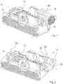
- Figure 1 shows a schematic view of the housing part 10 with an attached cable harness 90 portion.
- the cable harness portion 90 shown in figure 1 is just a portion of a real cable harness. The view is chosen to illustrate how the cable tie 70 is fastened to a fastening device 50 and guided around the cable harness 90 thereby holding the cable harness 90 tightly to the housing part 10.
- Figure 2 shows in a perspective view the housing part 10 of the electrical cable harness plug 1, comprising the housing part 10 with cavities 12 for receiving electric contact elements and the fastening device 50 to fasten the cable harness 90 that comprises the electrical contact elements.
- the electrical cable harness plug 1 furthermore comprising a cover 100 ( figure 3 ) to protect the contact elements.
- a housing transition portion 14 of the housing part and a cover transition portion 114 of the cover 100 cooperate with each other, to define a tube shaped guiding channel 20 for guiding the cable harness 90 through.
- the fastening device 50 is arranged inside the guiding channel 20.
- the fastening device 50 comprises means adapted to cooperate with a cable tie 70 such that it guides and holds the cable tie 70 in a holding direction Y perpendicular to an extension direction X of the guiding channel 20.
- Figure 3 shows the electrical cable harness plug 1 in a perspective view.
- the cover 100 is attached to the housing part 10 the transition portion 14 of the housing part and a cover transition portion 114 of the cover 100 cooperate with each other, to define the tube shaped guiding channel 20.
- the guiding channel 20 is arranged along the extension direction X perpendicular to a mating axis Z.
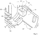
- FIG 4 shows the fastening device 50 of the electrical cable harness plug 1 in a perspective view.
- the fastening device 50 comprises at least one handle 52, comprising a first protrusion 53 and a second protrusion 54 protruding, spaced apart from each other, by a first distance 56 ( figure 5 ) from the housing transition portion 14 into the guiding channel 20.
- a handle bar 55 connects the free end of the first protrusion 53 and the free end of the second protrusion 54 in a second distance 57 ( figure 5 ) from the housing transition portion 14.
- the first protrusion 53 and the second protrusion 54 are arranged in a row along the extension direction X of the guiding channel 20.
- FIG. 5 shows a more detailed view of the fastening device 50.
- the fastening device 50 comprises at least one channel segment 60, comprising a first rib 63 and a second rib 64 protruding along the holding direction Y, spaced apart from each other by a third distance 66 ( figure 6 ) from the housing transition portion 14 into the guiding channel 20.
- a rib bar 65 connects a portion of the free end of the first rib 63 and a portion of the free end of the second rib 64 in a fourth distance 67 from the housing transition portion 14, thereby defining a tube shaped portion.
- Figure 6 shows a top view of the housing part 10 wherein the fastening device 50 comprises at least one handle 52 and at least one channel segment 60 arranged in a row along the holding direction Y.
- the guiding channel 20 comprises a channel first end 21 and a channel second end 22, wherein the channel first end is closer to the cavities 12 than the channel second end, whereby the fastening device 50 is located at the channel first end.
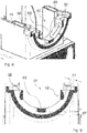
- Figure 7 shows a side view of the housing part 10 with a view direction along the holding direction Y, towards the guiding channel 20.
- Figure 8 shows the housing part 10 with a cut along the holding direction Y through the fastening device 50, in a perspective view.
- the first rib 63 is connected to the handle 52.
- the handle bar 55 comprises a guiding surface 58 located between the first protrusion 53 and the second protrusion 54, whereby the guiding surface 58 is sloped or curved to enlarge the area of the handle 52 where the cable tie 70 is inserted while assembling
- Figure 9 shows the cut view as shown in figure 8 now as front view looking in extension direction X. This view shows best the second distance 57 and the fourth distance 67 of the fastening device 50.
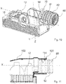
- Figure 10 shows in a perspective view of the housing part 10 with a fasted cable harness 90 and an attached corrugated tube 80.
- the guiding channel 20 comprises holding means to secure the corrugated tube 80 on the channel second end 22 of the guiding channel 20.
- the holding means comprises at least one holding rib 81 protruding along the holding direction Y from the housing transition portion 14 into the guiding channel 20, whereby the holding rib 81 cooperates with a narrowing 82 in the corrugated tube 80 to secure the corrugated tube.
- Figure 11 shows a cut view of the illustration shown in figure 10 (with a corrugated tube attached but without he cable harness) wherein the cut is carried out along the central line of the housing part 10.
- the cover 100 comprises on the inner side in the cover transition portion 114 a holding rib 102 that cooperates with a narrowing 82 in the corrugated tube 80.
Landscapes
- Engineering & Computer Science (AREA)
- Mechanical Engineering (AREA)
- Architecture (AREA)
- Civil Engineering (AREA)
- Structural Engineering (AREA)
- Details Of Connecting Devices For Male And Female Coupling (AREA)
- Connector Housings Or Holding Contact Members (AREA)
Priority Applications (5)
| Application Number | Priority Date | Filing Date | Title |
|---|---|---|---|
| EP17161625.3A EP3376606B1 (de) | 2017-03-17 | 2017-03-17 | Kabelbaumstecker |
| CN201810193388.XA CN108631110B (zh) | 2017-03-17 | 2018-03-09 | 电缆线束插头 |
| US15/920,033 US10516230B2 (en) | 2017-03-17 | 2018-03-13 | Electrical connector assembly |
| KR1020180030978A KR20180106969A (ko) | 2017-03-17 | 2018-03-16 | 케이블 하네스 플러그 |
| JP2018049238A JP2018156943A (ja) | 2017-03-17 | 2018-03-16 | ケーブルハーネスプラグ |
Applications Claiming Priority (1)
| Application Number | Priority Date | Filing Date | Title |
|---|---|---|---|
| EP17161625.3A EP3376606B1 (de) | 2017-03-17 | 2017-03-17 | Kabelbaumstecker |
Publications (2)
| Publication Number | Publication Date |
|---|---|
| EP3376606A1 true EP3376606A1 (de) | 2018-09-19 |
| EP3376606B1 EP3376606B1 (de) | 2021-05-05 |
Family
ID=58358495
Family Applications (1)
| Application Number | Title | Priority Date | Filing Date |
|---|---|---|---|
| EP17161625.3A Active EP3376606B1 (de) | 2017-03-17 | 2017-03-17 | Kabelbaumstecker |
Country Status (5)
| Country | Link |
|---|---|
| US (1) | US10516230B2 (de) |
| EP (1) | EP3376606B1 (de) |
| JP (1) | JP2018156943A (de) |
| KR (1) | KR20180106969A (de) |
| CN (1) | CN108631110B (de) |
Cited By (2)
| Publication number | Priority date | Publication date | Assignee | Title |
|---|---|---|---|---|
| CN112864760A (zh) * | 2019-11-08 | 2021-05-28 | 施洛伊尼格股份公司 | 线缆操纵设备和线缆加工设备 |
| FR3149940A1 (fr) * | 2023-06-16 | 2024-12-20 | Psa Automobiles Sa | Agrafe pour le montage d’un faisceau de cables electriques de gros diametres sur un vehicule automobile |
Families Citing this family (6)
| Publication number | Priority date | Publication date | Assignee | Title |
|---|---|---|---|---|
| DE102016109048A1 (de) * | 2016-05-17 | 2017-11-23 | Schlemmer Gmbh | Aufnahmevorrichtung und Kabelbaum |
| JP6792801B2 (ja) * | 2017-07-04 | 2020-12-02 | 住友電装株式会社 | 細長部材の保持構造 |
| JP7140733B2 (ja) * | 2019-09-26 | 2022-09-21 | 矢崎総業株式会社 | コネクタカバー |
| JP7274127B2 (ja) * | 2019-11-07 | 2023-05-16 | 株式会社オートネットワーク技術研究所 | コネクタ |
| JP7398056B2 (ja) * | 2020-06-17 | 2023-12-14 | 株式会社オートネットワーク技術研究所 | 電線カバー及びコネクタ構造 |
| JP7370682B2 (ja) * | 2021-05-13 | 2023-10-30 | 矢崎総業株式会社 | 構造体 |
Citations (5)
| Publication number | Priority date | Publication date | Assignee | Title |
|---|---|---|---|---|
| US20020055299A1 (en) * | 2000-08-02 | 2002-05-09 | Peter Zweigle | Cable harness plug having a securing device for the cable harness |
| US20070193002A1 (en) * | 2006-02-23 | 2007-08-23 | Kabushiki Kaisha Toshiba | Cable tying apparatus and electronic device having cable tying apparatus |
| JP2012119241A (ja) * | 2010-12-02 | 2012-06-21 | Jst Mfg Co Ltd | 電気コネクタ |
| EP2590271A1 (de) * | 2011-11-07 | 2013-05-08 | Sumitomo Wiring Systems, Ltd. | Stecker mit Drahtabdeckung und Montageverfahren dafür |
| GB2518076A (en) * | 2012-07-25 | 2015-03-11 | Yazaki Corp | Electrical-wire-protecting member |
Family Cites Families (18)
| Publication number | Priority date | Publication date | Assignee | Title |
|---|---|---|---|---|
| US4195899A (en) * | 1977-09-19 | 1980-04-01 | Bunker Ramo Corporation | Electrical connector with improved strain relief means |
| JPS5788980U (de) * | 1980-11-20 | 1982-06-01 | ||
| US4358178A (en) * | 1981-01-05 | 1982-11-09 | Western Electric Company, Inc. | Hood for multicontact connector |
| JPH0275923U (de) * | 1988-11-30 | 1990-06-11 | ||
| US5244415A (en) * | 1992-02-07 | 1993-09-14 | Harbor Electronics, Inc. | Shielded electrical connector and cable |
| US5211706A (en) * | 1992-06-09 | 1993-05-18 | Molex Incorporated | Strain relief shell for an electrical connector |
| JP2004288545A (ja) * | 2003-03-24 | 2004-10-14 | Yazaki Corp | コネクタ用プロテクタ |
| US7014498B1 (en) * | 2005-05-09 | 2006-03-21 | Lear Corporation | Safety closure for connectors with pivoting cover |
| JP4924889B2 (ja) * | 2007-05-09 | 2012-04-25 | 住友電装株式会社 | コネクタカバー |
| JP5798360B2 (ja) * | 2011-04-20 | 2015-10-21 | 矢崎総業株式会社 | 電線挿通部の結束バンド組付構造 |
| EP2520959B1 (de) * | 2011-05-05 | 2014-03-12 | CCS Technology, Inc. | Kabelzugentlastungsvorrichtung für Kabelenden und Kabelenden mit mindestens einer solchen Kabelzugentlastungsvorrichtung |
| JP5898013B2 (ja) * | 2012-07-25 | 2016-04-06 | 矢崎総業株式会社 | 電線保護部材 |
| JP2014059985A (ja) * | 2012-09-14 | 2014-04-03 | Hosiden Corp | コネクタ |
| JP6055260B2 (ja) * | 2012-10-05 | 2016-12-27 | 矢崎総業株式会社 | 充電コネクタ |
| CN202917723U (zh) * | 2012-10-09 | 2013-05-01 | 天津市柯文制模注塑有限公司 | 一种汽车线束连接器保护壳 |
| DE102014104211A1 (de) * | 2014-03-26 | 2015-10-01 | Bürkert Werke GmbH | Fluidmess- oder Fluidsteuerungsvorrichtung |
| EP3057182B1 (de) * | 2015-02-12 | 2019-04-03 | Aptiv Technologies Limited | Verbinder mit vormontiertem Leitungsadapter |
| JP2017059428A (ja) * | 2015-09-17 | 2017-03-23 | 住友電装株式会社 | 電線カバー |
-
2017
- 2017-03-17 EP EP17161625.3A patent/EP3376606B1/de active Active
-
2018
- 2018-03-09 CN CN201810193388.XA patent/CN108631110B/zh active Active
- 2018-03-13 US US15/920,033 patent/US10516230B2/en active Active
- 2018-03-16 JP JP2018049238A patent/JP2018156943A/ja active Pending
- 2018-03-16 KR KR1020180030978A patent/KR20180106969A/ko not_active Abandoned
Patent Citations (5)
| Publication number | Priority date | Publication date | Assignee | Title |
|---|---|---|---|---|
| US20020055299A1 (en) * | 2000-08-02 | 2002-05-09 | Peter Zweigle | Cable harness plug having a securing device for the cable harness |
| US20070193002A1 (en) * | 2006-02-23 | 2007-08-23 | Kabushiki Kaisha Toshiba | Cable tying apparatus and electronic device having cable tying apparatus |
| JP2012119241A (ja) * | 2010-12-02 | 2012-06-21 | Jst Mfg Co Ltd | 電気コネクタ |
| EP2590271A1 (de) * | 2011-11-07 | 2013-05-08 | Sumitomo Wiring Systems, Ltd. | Stecker mit Drahtabdeckung und Montageverfahren dafür |
| GB2518076A (en) * | 2012-07-25 | 2015-03-11 | Yazaki Corp | Electrical-wire-protecting member |
Cited By (2)
| Publication number | Priority date | Publication date | Assignee | Title |
|---|---|---|---|---|
| CN112864760A (zh) * | 2019-11-08 | 2021-05-28 | 施洛伊尼格股份公司 | 线缆操纵设备和线缆加工设备 |
| FR3149940A1 (fr) * | 2023-06-16 | 2024-12-20 | Psa Automobiles Sa | Agrafe pour le montage d’un faisceau de cables electriques de gros diametres sur un vehicule automobile |
Also Published As
| Publication number | Publication date |
|---|---|
| KR20180106969A (ko) | 2018-10-01 |
| EP3376606B1 (de) | 2021-05-05 |
| US10516230B2 (en) | 2019-12-24 |
| US20180269616A1 (en) | 2018-09-20 |
| JP2018156943A (ja) | 2018-10-04 |
| CN108631110B (zh) | 2020-06-26 |
| CN108631110A (zh) | 2018-10-09 |
Similar Documents
| Publication | Publication Date | Title |
|---|---|---|
| EP3376606B1 (de) | Kabelbaumstecker | |
| KR101798349B1 (ko) | 플러그 타입 커넥터용 보유 프레임 | |
| US6540547B2 (en) | Cable harness plug having a securing device for the cable harness | |
| JP5754380B2 (ja) | コネクタの電線保護部材 | |
| JP2006311785A (ja) | プロテクタ | |
| CN110065449B (zh) | 电接线盒和保护构件的连接结构 | |
| KR20140034296A (ko) | 방수 커넥터 및 그 제조방법 | |
| US9525278B2 (en) | Electrical-wire-protecting member using tying member | |
| US6575775B2 (en) | Connector with shorting terminal | |
| CN104080655A (zh) | 带有夹具的线束和具有该带有夹具的线束的线束 | |
| JP6793047B2 (ja) | プロテクタおよびワイヤハーネス | |
| JP2016009527A (ja) | コネクタ | |
| US8263865B2 (en) | Wire connection unit | |
| US9343889B2 (en) | Electric wire fixing device | |
| KR101513281B1 (ko) | 커넥터의 단자 보호장치 | |
| JP6041211B2 (ja) | 自動変速機用保持プレート、およびこれを備えた配線ユニット | |
| US9240678B2 (en) | Electrical junction box | |
| JP6570897B2 (ja) | 電線経路規制用カバー | |
| JP5703011B2 (ja) | ワイヤハーネスのアース接続構造 | |
| CN104183969A (zh) | 保护罩 | |
| KR200465856Y1 (ko) | 커넥터의 와이어커버 결합구조 | |
| JP7158728B2 (ja) | コネクタ保護装置、ホルダ、および保護カバー | |
| JP2013251115A (ja) | 電線保護構造 | |
| CN210122097U (zh) | 高压电缆保护构件 | |
| CN114678818B (zh) | 电气接线箱 |
Legal Events
| Date | Code | Title | Description |
|---|---|---|---|
| PUAI | Public reference made under article 153(3) epc to a published international application that has entered the european phase |
Free format text: ORIGINAL CODE: 0009012 |
|
| STAA | Information on the status of an ep patent application or granted ep patent |
Free format text: STATUS: THE APPLICATION HAS BEEN PUBLISHED |
|
| AK | Designated contracting states |
Kind code of ref document: A1 Designated state(s): AL AT BE BG CH CY CZ DE DK EE ES FI FR GB GR HR HU IE IS IT LI LT LU LV MC MK MT NL NO PL PT RO RS SE SI SK SM TR |
|
| AX | Request for extension of the european patent |
Extension state: BA ME |
|
| RAP1 | Party data changed (applicant data changed or rights of an application transferred) |
Owner name: APTIV TECHNOLOGIES LIMITED |
|
| STAA | Information on the status of an ep patent application or granted ep patent |
Free format text: STATUS: REQUEST FOR EXAMINATION WAS MADE |
|
| 17P | Request for examination filed |
Effective date: 20190319 |
|
| RBV | Designated contracting states (corrected) |
Designated state(s): AL AT BE BG CH CY CZ DE DK EE ES FI FR GB GR HR HU IE IS IT LI LT LU LV MC MK MT NL NO PL PT RO RS SE SI SK SM TR |
|
| STAA | Information on the status of an ep patent application or granted ep patent |
Free format text: STATUS: EXAMINATION IS IN PROGRESS |
|
| 17Q | First examination report despatched |
Effective date: 20190611 |
|
| GRAP | Despatch of communication of intention to grant a patent |
Free format text: ORIGINAL CODE: EPIDOSNIGR1 |
|
| STAA | Information on the status of an ep patent application or granted ep patent |
Free format text: STATUS: GRANT OF PATENT IS INTENDED |
|
| INTG | Intention to grant announced |
Effective date: 20201113 |
|
| GRAS | Grant fee paid |
Free format text: ORIGINAL CODE: EPIDOSNIGR3 |
|
| GRAA | (expected) grant |
Free format text: ORIGINAL CODE: 0009210 |
|
| STAA | Information on the status of an ep patent application or granted ep patent |
Free format text: STATUS: THE PATENT HAS BEEN GRANTED |
|
| AK | Designated contracting states |
Kind code of ref document: B1 Designated state(s): AL AT BE BG CH CY CZ DE DK EE ES FI FR GB GR HR HU IE IS IT LI LT LU LV MC MK MT NL NO PL PT RO RS SE SI SK SM TR |
|
| REG | Reference to a national code |
Ref country code: GB Ref legal event code: FG4D |
|
| REG | Reference to a national code |
Ref country code: CH Ref legal event code: EP |
|
| REG | Reference to a national code |
Ref country code: AT Ref legal event code: REF Ref document number: 1390993 Country of ref document: AT Kind code of ref document: T Effective date: 20210515 |
|
| REG | Reference to a national code |
Ref country code: IE Ref legal event code: FG4D |
|
| REG | Reference to a national code |
Ref country code: DE Ref legal event code: R096 Ref document number: 602017037912 Country of ref document: DE |
|
| REG | Reference to a national code |
Ref country code: LT Ref legal event code: MG9D |
|
| REG | Reference to a national code |
Ref country code: AT Ref legal event code: MK05 Ref document number: 1390993 Country of ref document: AT Kind code of ref document: T Effective date: 20210505 |
|
| PG25 | Lapsed in a contracting state [announced via postgrant information from national office to epo] |
Ref country code: FI Free format text: LAPSE BECAUSE OF FAILURE TO SUBMIT A TRANSLATION OF THE DESCRIPTION OR TO PAY THE FEE WITHIN THE PRESCRIBED TIME-LIMIT Effective date: 20210505 Ref country code: LT Free format text: LAPSE BECAUSE OF FAILURE TO SUBMIT A TRANSLATION OF THE DESCRIPTION OR TO PAY THE FEE WITHIN THE PRESCRIBED TIME-LIMIT Effective date: 20210505 Ref country code: HR Free format text: LAPSE BECAUSE OF FAILURE TO SUBMIT A TRANSLATION OF THE DESCRIPTION OR TO PAY THE FEE WITHIN THE PRESCRIBED TIME-LIMIT Effective date: 20210505 Ref country code: BG Free format text: LAPSE BECAUSE OF FAILURE TO SUBMIT A TRANSLATION OF THE DESCRIPTION OR TO PAY THE FEE WITHIN THE PRESCRIBED TIME-LIMIT Effective date: 20210805 Ref country code: AT Free format text: LAPSE BECAUSE OF FAILURE TO SUBMIT A TRANSLATION OF THE DESCRIPTION OR TO PAY THE FEE WITHIN THE PRESCRIBED TIME-LIMIT Effective date: 20210505 |
|
| PG25 | Lapsed in a contracting state [announced via postgrant information from national office to epo] |
Ref country code: IS Free format text: LAPSE BECAUSE OF FAILURE TO SUBMIT A TRANSLATION OF THE DESCRIPTION OR TO PAY THE FEE WITHIN THE PRESCRIBED TIME-LIMIT Effective date: 20210905 Ref country code: LV Free format text: LAPSE BECAUSE OF FAILURE TO SUBMIT A TRANSLATION OF THE DESCRIPTION OR TO PAY THE FEE WITHIN THE PRESCRIBED TIME-LIMIT Effective date: 20210505 Ref country code: GR Free format text: LAPSE BECAUSE OF FAILURE TO SUBMIT A TRANSLATION OF THE DESCRIPTION OR TO PAY THE FEE WITHIN THE PRESCRIBED TIME-LIMIT Effective date: 20210806 Ref country code: PL Free format text: LAPSE BECAUSE OF FAILURE TO SUBMIT A TRANSLATION OF THE DESCRIPTION OR TO PAY THE FEE WITHIN THE PRESCRIBED TIME-LIMIT Effective date: 20210505 Ref country code: PT Free format text: LAPSE BECAUSE OF FAILURE TO SUBMIT A TRANSLATION OF THE DESCRIPTION OR TO PAY THE FEE WITHIN THE PRESCRIBED TIME-LIMIT Effective date: 20210906 Ref country code: NO Free format text: LAPSE BECAUSE OF FAILURE TO SUBMIT A TRANSLATION OF THE DESCRIPTION OR TO PAY THE FEE WITHIN THE PRESCRIBED TIME-LIMIT Effective date: 20210805 Ref country code: RS Free format text: LAPSE BECAUSE OF FAILURE TO SUBMIT A TRANSLATION OF THE DESCRIPTION OR TO PAY THE FEE WITHIN THE PRESCRIBED TIME-LIMIT Effective date: 20210505 Ref country code: SE Free format text: LAPSE BECAUSE OF FAILURE TO SUBMIT A TRANSLATION OF THE DESCRIPTION OR TO PAY THE FEE WITHIN THE PRESCRIBED TIME-LIMIT Effective date: 20210505 |
|
| REG | Reference to a national code |
Ref country code: NL Ref legal event code: MP Effective date: 20210505 |
|
| PG25 | Lapsed in a contracting state [announced via postgrant information from national office to epo] |
Ref country code: NL Free format text: LAPSE BECAUSE OF FAILURE TO SUBMIT A TRANSLATION OF THE DESCRIPTION OR TO PAY THE FEE WITHIN THE PRESCRIBED TIME-LIMIT Effective date: 20210505 |
|
| PG25 | Lapsed in a contracting state [announced via postgrant information from national office to epo] |
Ref country code: SM Free format text: LAPSE BECAUSE OF FAILURE TO SUBMIT A TRANSLATION OF THE DESCRIPTION OR TO PAY THE FEE WITHIN THE PRESCRIBED TIME-LIMIT Effective date: 20210505 Ref country code: SK Free format text: LAPSE BECAUSE OF FAILURE TO SUBMIT A TRANSLATION OF THE DESCRIPTION OR TO PAY THE FEE WITHIN THE PRESCRIBED TIME-LIMIT Effective date: 20210505 Ref country code: DK Free format text: LAPSE BECAUSE OF FAILURE TO SUBMIT A TRANSLATION OF THE DESCRIPTION OR TO PAY THE FEE WITHIN THE PRESCRIBED TIME-LIMIT Effective date: 20210505 Ref country code: CZ Free format text: LAPSE BECAUSE OF FAILURE TO SUBMIT A TRANSLATION OF THE DESCRIPTION OR TO PAY THE FEE WITHIN THE PRESCRIBED TIME-LIMIT Effective date: 20210505 Ref country code: EE Free format text: LAPSE BECAUSE OF FAILURE TO SUBMIT A TRANSLATION OF THE DESCRIPTION OR TO PAY THE FEE WITHIN THE PRESCRIBED TIME-LIMIT Effective date: 20210505 Ref country code: RO Free format text: LAPSE BECAUSE OF FAILURE TO SUBMIT A TRANSLATION OF THE DESCRIPTION OR TO PAY THE FEE WITHIN THE PRESCRIBED TIME-LIMIT Effective date: 20210505 Ref country code: ES Free format text: LAPSE BECAUSE OF FAILURE TO SUBMIT A TRANSLATION OF THE DESCRIPTION OR TO PAY THE FEE WITHIN THE PRESCRIBED TIME-LIMIT Effective date: 20210505 |
|
| REG | Reference to a national code |
Ref country code: DE Ref legal event code: R097 Ref document number: 602017037912 Country of ref document: DE |
|
| PLBE | No opposition filed within time limit |
Free format text: ORIGINAL CODE: 0009261 |
|
| STAA | Information on the status of an ep patent application or granted ep patent |
Free format text: STATUS: NO OPPOSITION FILED WITHIN TIME LIMIT |
|
| 26N | No opposition filed |
Effective date: 20220208 |
|
| PG25 | Lapsed in a contracting state [announced via postgrant information from national office to epo] |
Ref country code: IS Free format text: LAPSE BECAUSE OF FAILURE TO SUBMIT A TRANSLATION OF THE DESCRIPTION OR TO PAY THE FEE WITHIN THE PRESCRIBED TIME-LIMIT Effective date: 20210905 Ref country code: AL Free format text: LAPSE BECAUSE OF FAILURE TO SUBMIT A TRANSLATION OF THE DESCRIPTION OR TO PAY THE FEE WITHIN THE PRESCRIBED TIME-LIMIT Effective date: 20210505 |
|
| PG25 | Lapsed in a contracting state [announced via postgrant information from national office to epo] |
Ref country code: IT Free format text: LAPSE BECAUSE OF FAILURE TO SUBMIT A TRANSLATION OF THE DESCRIPTION OR TO PAY THE FEE WITHIN THE PRESCRIBED TIME-LIMIT Effective date: 20210505 |
|
| PG25 | Lapsed in a contracting state [announced via postgrant information from national office to epo] |
Ref country code: MC Free format text: LAPSE BECAUSE OF FAILURE TO SUBMIT A TRANSLATION OF THE DESCRIPTION OR TO PAY THE FEE WITHIN THE PRESCRIBED TIME-LIMIT Effective date: 20210505 |
|
| REG | Reference to a national code |
Ref country code: CH Ref legal event code: PL |
|
| REG | Reference to a national code |
Ref country code: BE Ref legal event code: MM Effective date: 20220331 |
|
| PG25 | Lapsed in a contracting state [announced via postgrant information from national office to epo] |
Ref country code: LU Free format text: LAPSE BECAUSE OF NON-PAYMENT OF DUE FEES Effective date: 20220317 Ref country code: LI Free format text: LAPSE BECAUSE OF NON-PAYMENT OF DUE FEES Effective date: 20220331 Ref country code: IE Free format text: LAPSE BECAUSE OF NON-PAYMENT OF DUE FEES Effective date: 20220317 Ref country code: CH Free format text: LAPSE BECAUSE OF NON-PAYMENT OF DUE FEES Effective date: 20220331 |
|
| PG25 | Lapsed in a contracting state [announced via postgrant information from national office to epo] |
Ref country code: BE Free format text: LAPSE BECAUSE OF NON-PAYMENT OF DUE FEES Effective date: 20220331 |
|
| P01 | Opt-out of the competence of the unified patent court (upc) registered |
Effective date: 20230420 |
|
| PG25 | Lapsed in a contracting state [announced via postgrant information from national office to epo] |
Ref country code: HU Free format text: LAPSE BECAUSE OF FAILURE TO SUBMIT A TRANSLATION OF THE DESCRIPTION OR TO PAY THE FEE WITHIN THE PRESCRIBED TIME-LIMIT; INVALID AB INITIO Effective date: 20170317 |
|
| PG25 | Lapsed in a contracting state [announced via postgrant information from national office to epo] |
Ref country code: MK Free format text: LAPSE BECAUSE OF FAILURE TO SUBMIT A TRANSLATION OF THE DESCRIPTION OR TO PAY THE FEE WITHIN THE PRESCRIBED TIME-LIMIT Effective date: 20210505 Ref country code: CY Free format text: LAPSE BECAUSE OF FAILURE TO SUBMIT A TRANSLATION OF THE DESCRIPTION OR TO PAY THE FEE WITHIN THE PRESCRIBED TIME-LIMIT Effective date: 20210505 |
|
| PG25 | Lapsed in a contracting state [announced via postgrant information from national office to epo] |
Ref country code: MT Free format text: LAPSE BECAUSE OF FAILURE TO SUBMIT A TRANSLATION OF THE DESCRIPTION OR TO PAY THE FEE WITHIN THE PRESCRIBED TIME-LIMIT Effective date: 20210505 |
|
| REG | Reference to a national code |
Ref country code: DE Ref legal event code: R081 Ref document number: 602017037912 Country of ref document: DE Owner name: APTIV TECHNOLOGIES AG, CH Free format text: FORMER OWNER: APTIV TECHNOLOGIES LIMITED, ST. MICHAEL, BB |
|
| PG25 | Lapsed in a contracting state [announced via postgrant information from national office to epo] |
Ref country code: TR Free format text: LAPSE BECAUSE OF FAILURE TO SUBMIT A TRANSLATION OF THE DESCRIPTION OR TO PAY THE FEE WITHIN THE PRESCRIBED TIME-LIMIT Effective date: 20210505 |
|
| PGFP | Annual fee paid to national office [announced via postgrant information from national office to epo] |
Ref country code: GB Payment date: 20260223 Year of fee payment: 10 |
|
| PGFP | Annual fee paid to national office [announced via postgrant information from national office to epo] |
Ref country code: DE Payment date: 20260223 Year of fee payment: 10 |
|
| PGFP | Annual fee paid to national office [announced via postgrant information from national office to epo] |
Ref country code: FR Payment date: 20260303 Year of fee payment: 10 |