EP3376608A2 - Verbinderanordnung und verfahren zur montage dieser verbinderanordnung - Google Patents
Verbinderanordnung und verfahren zur montage dieser verbinderanordnung Download PDFInfo
- Publication number
- EP3376608A2 EP3376608A2 EP18158712.2A EP18158712A EP3376608A2 EP 3376608 A2 EP3376608 A2 EP 3376608A2 EP 18158712 A EP18158712 A EP 18158712A EP 3376608 A2 EP3376608 A2 EP 3376608A2
- Authority
- EP
- European Patent Office
- Prior art keywords
- connector
- screw
- button
- locked position
- mating connector
- Prior art date
- Legal status (The legal status is an assumption and is not a legal conclusion. Google has not performed a legal analysis and makes no representation as to the accuracy of the status listed.)
- Granted
Links
Images

Classifications
-
- H—ELECTRICITY
- H01—ELECTRIC ELEMENTS
- H01R—ELECTRICALLY-CONDUCTIVE CONNECTIONS; STRUCTURAL ASSOCIATIONS OF A PLURALITY OF MUTUALLY-INSULATED ELECTRICAL CONNECTING ELEMENTS; COUPLING DEVICES; CURRENT COLLECTORS
- H01R13/00—Details of coupling devices of the kinds covered by groups H01R12/70 or H01R24/00 - H01R33/00
- H01R13/62—Means for facilitating engagement or disengagement of coupling parts or for holding them in engagement
- H01R13/621—Bolt, set screw or screw clamp
- H01R13/6215—Bolt, set screw or screw clamp using one or more bolts
-
- H—ELECTRICITY
- H01—ELECTRIC ELEMENTS
- H01R—ELECTRICALLY-CONDUCTIVE CONNECTIONS; STRUCTURAL ASSOCIATIONS OF A PLURALITY OF MUTUALLY-INSULATED ELECTRICAL CONNECTING ELEMENTS; COUPLING DEVICES; CURRENT COLLECTORS
- H01R13/00—Details of coupling devices of the kinds covered by groups H01R12/70 or H01R24/00 - H01R33/00
- H01R13/62—Means for facilitating engagement or disengagement of coupling parts or for holding them in engagement
- H01R13/621—Bolt, set screw or screw clamp
-
- F—MECHANICAL ENGINEERING; LIGHTING; HEATING; WEAPONS; BLASTING
- F16—ENGINEERING ELEMENTS AND UNITS; GENERAL MEASURES FOR PRODUCING AND MAINTAINING EFFECTIVE FUNCTIONING OF MACHINES OR INSTALLATIONS; THERMAL INSULATION IN GENERAL
- F16B—DEVICES FOR FASTENING OR SECURING CONSTRUCTIONAL ELEMENTS OR MACHINE PARTS TOGETHER, e.g. NAILS, BOLTS, CIRCLIPS, CLAMPS, CLIPS OR WEDGES; JOINTS OR JOINTING
- F16B37/00—Nuts or like thread-engaging members
- F16B37/14—Cap nuts; Nut caps or bolt caps
-
- H—ELECTRICITY
- H01—ELECTRIC ELEMENTS
- H01R—ELECTRICALLY-CONDUCTIVE CONNECTIONS; STRUCTURAL ASSOCIATIONS OF A PLURALITY OF MUTUALLY-INSULATED ELECTRICAL CONNECTING ELEMENTS; COUPLING DEVICES; CURRENT COLLECTORS
- H01R13/00—Details of coupling devices of the kinds covered by groups H01R12/70 or H01R24/00 - H01R33/00
- H01R13/62—Means for facilitating engagement or disengagement of coupling parts or for holding them in engagement
- H01R13/629—Additional means for facilitating engagement or disengagement of coupling parts, e.g. aligning or guiding means, levers, gas pressure electrical locking indicators, manufacturing tolerances
-
- H—ELECTRICITY
- H01—ELECTRIC ELEMENTS
- H01R—ELECTRICALLY-CONDUCTIVE CONNECTIONS; STRUCTURAL ASSOCIATIONS OF A PLURALITY OF MUTUALLY-INSULATED ELECTRICAL CONNECTING ELEMENTS; COUPLING DEVICES; CURRENT COLLECTORS
- H01R13/00—Details of coupling devices of the kinds covered by groups H01R12/70 or H01R24/00 - H01R33/00
- H01R13/62—Means for facilitating engagement or disengagement of coupling parts or for holding them in engagement
- H01R13/629—Additional means for facilitating engagement or disengagement of coupling parts, e.g. aligning or guiding means, levers, gas pressure electrical locking indicators, manufacturing tolerances
- H01R13/633—Additional means for facilitating engagement or disengagement of coupling parts, e.g. aligning or guiding means, levers, gas pressure electrical locking indicators, manufacturing tolerances for disengagement only
- H01R13/6335—Additional means for facilitating engagement or disengagement of coupling parts, e.g. aligning or guiding means, levers, gas pressure electrical locking indicators, manufacturing tolerances for disengagement only comprising a handle
-
- H—ELECTRICITY
- H01—ELECTRIC ELEMENTS
- H01R—ELECTRICALLY-CONDUCTIVE CONNECTIONS; STRUCTURAL ASSOCIATIONS OF A PLURALITY OF MUTUALLY-INSULATED ELECTRICAL CONNECTING ELEMENTS; COUPLING DEVICES; CURRENT COLLECTORS
- H01R13/00—Details of coupling devices of the kinds covered by groups H01R12/70 or H01R24/00 - H01R33/00
- H01R13/62—Means for facilitating engagement or disengagement of coupling parts or for holding them in engagement
- H01R13/639—Additional means for holding or locking coupling parts together, after engagement, e.g. separate keylock, retainer strap
-
- H—ELECTRICITY
- H01—ELECTRIC ELEMENTS
- H01R—ELECTRICALLY-CONDUCTIVE CONNECTIONS; STRUCTURAL ASSOCIATIONS OF A PLURALITY OF MUTUALLY-INSULATED ELECTRICAL CONNECTING ELEMENTS; COUPLING DEVICES; CURRENT COLLECTORS
- H01R13/00—Details of coupling devices of the kinds covered by groups H01R12/70 or H01R24/00 - H01R33/00
- H01R13/64—Means for preventing incorrect coupling
- H01R13/641—Means for preventing incorrect coupling by indicating incorrect coupling; by indicating correct or full engagement
-
- H—ELECTRICITY
- H01—ELECTRIC ELEMENTS
- H01R—ELECTRICALLY-CONDUCTIVE CONNECTIONS; STRUCTURAL ASSOCIATIONS OF A PLURALITY OF MUTUALLY-INSULATED ELECTRICAL CONNECTING ELEMENTS; COUPLING DEVICES; CURRENT COLLECTORS
- H01R43/00—Apparatus or processes specially adapted for manufacturing, assembling, maintaining, or repairing of line connectors or current collectors or for joining electric conductors
- H01R43/26—Apparatus or processes specially adapted for manufacturing, assembling, maintaining, or repairing of line connectors or current collectors or for joining electric conductors for engaging or disengaging the two parts of a coupling device
-
- F—MECHANICAL ENGINEERING; LIGHTING; HEATING; WEAPONS; BLASTING
- F16—ENGINEERING ELEMENTS AND UNITS; GENERAL MEASURES FOR PRODUCING AND MAINTAINING EFFECTIVE FUNCTIONING OF MACHINES OR INSTALLATIONS; THERMAL INSULATION IN GENERAL
- F16B—DEVICES FOR FASTENING OR SECURING CONSTRUCTIONAL ELEMENTS OR MACHINE PARTS TOGETHER, e.g. NAILS, BOLTS, CIRCLIPS, CLAMPS, CLIPS OR WEDGES; JOINTS OR JOINTING
- F16B2/00—Friction-grip releasable fastenings
- F16B2/20—Clips, i.e. with gripping action effected solely by the inherent resistance to deformation of the material of the fastening
- F16B2/22—Clips, i.e. with gripping action effected solely by the inherent resistance to deformation of the material of the fastening of resilient material, e.g. rubbery material
-
- F—MECHANICAL ENGINEERING; LIGHTING; HEATING; WEAPONS; BLASTING
- F16—ENGINEERING ELEMENTS AND UNITS; GENERAL MEASURES FOR PRODUCING AND MAINTAINING EFFECTIVE FUNCTIONING OF MACHINES OR INSTALLATIONS; THERMAL INSULATION IN GENERAL
- F16B—DEVICES FOR FASTENING OR SECURING CONSTRUCTIONAL ELEMENTS OR MACHINE PARTS TOGETHER, e.g. NAILS, BOLTS, CIRCLIPS, CLAMPS, CLIPS OR WEDGES; JOINTS OR JOINTING
- F16B2200/00—Constructional details of connections not covered for in other groups of this subclass
- F16B2200/95—Constructional details of connections not covered for in other groups of this subclass with markings, colours, indicators or the like
-
- F—MECHANICAL ENGINEERING; LIGHTING; HEATING; WEAPONS; BLASTING
- F16—ENGINEERING ELEMENTS AND UNITS; GENERAL MEASURES FOR PRODUCING AND MAINTAINING EFFECTIVE FUNCTIONING OF MACHINES OR INSTALLATIONS; THERMAL INSULATION IN GENERAL
- F16B—DEVICES FOR FASTENING OR SECURING CONSTRUCTIONAL ELEMENTS OR MACHINE PARTS TOGETHER, e.g. NAILS, BOLTS, CIRCLIPS, CLAMPS, CLIPS OR WEDGES; JOINTS OR JOINTING
- F16B2200/00—Constructional details of connections not covered for in other groups of this subclass
- F16B2200/99—Fasteners with means for avoiding incorrect assembly or positioning
-
- F—MECHANICAL ENGINEERING; LIGHTING; HEATING; WEAPONS; BLASTING
- F16—ENGINEERING ELEMENTS AND UNITS; GENERAL MEASURES FOR PRODUCING AND MAINTAINING EFFECTIVE FUNCTIONING OF MACHINES OR INSTALLATIONS; THERMAL INSULATION IN GENERAL
- F16B—DEVICES FOR FASTENING OR SECURING CONSTRUCTIONAL ELEMENTS OR MACHINE PARTS TOGETHER, e.g. NAILS, BOLTS, CIRCLIPS, CLAMPS, CLIPS OR WEDGES; JOINTS OR JOINTING
- F16B41/00—Measures against loss of bolts, nuts, or pins; Measures against unauthorised operation of bolts, nuts or pins
- F16B41/005—Measures against unauthorised operation of bolts, nuts or pins
Definitions
- the invention relates to the field of connectors, and in particular, but not exclusively, the field of electrical connectors for motor vehicles, such as for example electrical power connectors.
- Figure 1 shows an example of a connector assembly, of the prior art, for high voltage currents.
- the connector assembly 1 comprises a connector 2 and a mating connector 3.
- the connector 2 comprises for example pins (male contacts) connected to electrical cables 4.
- the mating connector 3 includes for example female contacts, into which the pins of the connector 2 must be inserted. These female contacts are electrically connected for example to electrical conducting bars ("busbars") and/or to devices 5 (current converters, motors etc.), accommodated in the mating connector 3.
- the connector 2 is assembled on the mating connector 3, then the connector 2 and the mating connector 3 are fastened to each other by means of screws 6 engaged in an orifice disposed in a flange 7 on the connector 2 side, before being screwed to the mating connector 3.
- Fastening connectors by means of screws generally gives rise to a problem of checking that screwing is complete and sufficient.
- the electrical connection may not be established or may be broken after a certain time due to the effect of vibration for example.
- Equipping assembly lines with specific checking means at the screwing tool is generally perceived as a costly investment and does not always fully resolve the problem of checking that screwing is complete.
- screw fastening is sometimes avoided, as it can take longer to accomplish than clip-on fastening for example, it also needs relatively unobstructed access to the screw etc.
- One aim of the invention is to provide a solution for improving checking, in an affordable, simple and reliable manner, that screwing is complete when fastening a connector to a mating connector.
- a connector assembly comprising a connector and a mating connector.
- This connector and this mating connector are fastened to each other by means of at least one screw.
- This screw includes a shank and a head. The shank is engaged in an orifice disposed in the connector and the screw head is held, by the connector, on one side of this orifice.
- the connector and the mating connector are in a connected position when the screw is in a position called “final fastened position", that is to say when it is screwed until the connector and the mating connector are tightened on each other at, that is to say in the vicinity, of the screw.
- the connector or the mating connector includes a button.
- This button constitutes means of ensuring that the screw is screwed in the final fastened position.
- This button is mobile, and can be moved between a first locked position and a second locked position distinct from the first locked position. In the first locked position, the button authorizes screwing or unscrewing of the screw. However, in the first locked position, the button cannot be moved if the screw is not in the final fastened position.
- the connector assembly according to the invention can potentially include one or other of the following characteristics, considered separately or combined:
- the invention is a connector including at least one orifice and a screw with a shank engaged in the orifice and a screw head held on the connector on one side of this orifice.
- This connector furthermore includes a button, mobile between
- This connector can potentially include one or other of the following characteristics, considered separately or combined:.
- the invention is a method for assembling a connector assembly comprising a connector and a mating connector, in which
- the term "mating connector” generally and broadly designates any element intended to be electrically connected to a connector. It can therefore be another connector, a housing on which connection components are assembled, a wall through which an electrical connection must be made, etc.
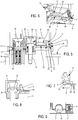
- FIG. 1 Several embodiment examples of a connector assembly 1 or of a connector conforming to the invention are illustrated on Figures 2 to 4 .
- the connector illustrated on Figure 2 includes a housing 8 with a flange 7.
- the housing 8 encloses power contacts (not illustrated on this figure) connected to electrical cables 4, as well as contacts 13 forming part of a circuit for controlling the supply of electrical current to the power contacts (see Figure 5 ).
- a button 9 is assembled to slide on the flange 7.
- a screw 6 is inserted in an orifice 10 disposed in the flange 7. This embodiment will be described in more detail in relation to Figures 5 to 9 .
- Figure 3 illustrates a connector assembly 1 with a connector 2 and a mating connector 3.
- the connector 2 corresponds for example to a female contact mount, one end of which is connected to an electrical cable 4.
- the mating connector 3 is in two parts in this case. It includes an interface in the form of a wall 11 and a male contact mount 32.
- the connector 2 includes a housing 8 and a flange 7.
- the housing 8 passes through the wall 11.
- the wall 11 is metal.
- the male contact mount 32 is fastened to the other side of the wall 11 relative to the connector 2 and partially covers the part of the housing 8 situated on the other side of the wall 11 relative to the flange 7.
- the male contact mount 32 accommodates a male contact 13 attached (for example screwed) to a busbar 12.
- the contact 13 is a power contact.
- the housing 8 isolates the female contact housed in the connector 2 from the wall 11.
- a button 9 is assembled to slide on the flange 7.
- a screw 6 is inserted into an orifice 10 disposed in the flange 7.
- the screw 6 is screwed into a threaded bore made in the wall 11 of the mating connector 3.
- the screw 6 passes through the flange 7 close to the portion of the housing accommodating the contact 13.
- the connector 2 only includes one way and one screw 6.
- Figure 4 also illustrates a connector assembly with a connector 2 and a mating connector 3.
- the connector 2 includes two ways with contacts (not visible but similar for example to the contacts of the embodiment of Figure 3 ), but just one screw 6 passing through the flange 7 between the two portions of the housing 8 each respectively accommodating a contact.
- the contacts are power contacts.
- Figure 5 illustrates, in section, a connector assembly 1, with the connector of Figure 2 , as well as a mating connector 3 (as for the embodiments described in relation to Figures 3 and 4 , the mating connector 3 includes an interface, in the form of a wall 11, and a male contact mount 32).
- the connector 2 and the mating connector 3 are in the pre-coupling position.
- the connector 2 and the mating connector 3 are positioned one above the other (potentially, as illustrated on Figure 5 , partially engaged one inside the other and with the screw partially screwed), but the contacts 13 (in this case, the contacts of a shunt 14) of the connector 2 and the contacts 15 of the mating connector 3 are not connected.
- the contacts 13 of the shunt 14 and the contacts 15 of the mating connector 3 correspond to those of a device for controlling the supply of electrical current delivered to power contacts, not illustrated.
- the contacts 15 of this controlling device are not connected by the shunt 14, the connector 2 and the mating connector 3 are not supplied with high voltage current.
- the connector assembly 1 it is therefore important to be able to ensure that the connector 2 and the mating connector 3 are truly coupled.
- the button 9 is in its first locked position.
- the button 9 is made from a single moulded piece. It comprises a slide block 16, a cover 17, blocking means 18 and a support 19.
- the cover 17 is connected to the support 19 by a flexible strip 20.
- the support 19 is connected to two pads 21 (see Figure 6 ) situated either side of the support 19 and forming the slide block 16.
- the slide block 16 is U-shaped, the two pads 21 each respectively corresponding to a branch of this U.
- the support 19 is connected to the central part of this U, situated between the branches of the U.
- the central part of the U is flexibly and elastically articulated on the branches of the U.
- the support 19 can therefore rock around an axis of articulation X (perpendicular to the plane of Figures 5 to 8 , see Figure 6 ) and become inserted, at least partially, between the branches of the U when pressure is exerted downwards on the button 9, in order to lift the cover 17.
- the pads 21 are assembled to slide each respectively in a slide 22 disposed in the housing 8. They are therefore guided in the movement, along a direction of actuation A (perpendicular to the axis of articulation X), of the button 9 between its first and second locked positions (corresponding respectively to Figures 5 and 8 for example).
- the blocking means 18 are essentially in the shape of front lugs 23 and rear lugs 24 cooperating with a holding element 25, here in the form of a beam made in one piece with the housing 8.
- the two rear lugs 24 are situated in the extension of the branches of the U forming the slide block 16, hence essentially in the extension of the pads 21 along the direction of actuation A, but they do not cooperate with the slides 22.
- the button 9 is in its first locked position. In this position, with the front lugs 23 and rear lugs 24 being stopped on the holding element 25, along the direction of actuation A, the blocking means 18 hold the button 9 on the holding element 25.
- the screw 6 includes a head 26 and a shank 27.
- the shank 27 is threaded and is screwed into a bore 28 disposed in the mating connector 3.
- the cover 17 does not cover the screw head 26 and a tool can, depending on the type of screw head 26, either be inserted in a recess 31 (see Figure 6 ) made in the screw head 26 in order to drive the screw 6 rotationally around its longitudinal axis, or be placed on or around the screw head 26, also to drive the screw 6 rotationally around its longitudinal axis.
- the button 9 is released from the holding element and the cover 17 can pass under the bridge 30.
- the button 9 can then be moved from its first locked position to its second locked position (see Figure 8 ).
- the cover 17 is positioned on the screw head 26. Its curved shape, relatively complementary to the shape of the screw head 26 on one hand, and the elastic nature of the flexible strip 20, which tends to press the cover 17 on the screw head 26 on the other hand, assist with blocking and locking the button 9 in this position.
- the button 9 cannot be released from this position without a deliberate and appropriate action on the part of an operator to move the button 9 back to its first locked position.
- the operator must effectively pull the button along the direction of actuation by moving the button 9 away from the screw 6 and overcoming the force due to the fit between the respective shapes of the cover 17 on the screw head 26 and the pressure exerted by the flexible strip 20 on the cover 17. This operation makes it possible to guarantee that the button 9 can only be moved from its second locked position to its first locked position by a deliberate action.
- the button 9 can be assembled to be mobile on the mating connector 3, unblocking the button 9 to allow it to be moved from its first locked position to its second locked position is achieved by interaction with the connector 2 when the connector 2 is sufficiently close to the mating connector 3 and when the connector 2 and the mating connector 3 are in the connected position, coupled, with the screw 6 in its final fastened position.
Landscapes
- Engineering & Computer Science (AREA)
- General Engineering & Computer Science (AREA)
- Manufacturing & Machinery (AREA)
- Mechanical Engineering (AREA)
- Details Of Connecting Devices For Male And Female Coupling (AREA)
Applications Claiming Priority (1)
| Application Number | Priority Date | Filing Date | Title |
|---|---|---|---|
| FR1752202A FR3064121B1 (fr) | 2017-03-17 | 2017-03-17 | Ensemble de connecteurs et procede d'assemblage de cet ensemble de connecteurs |
Publications (3)
| Publication Number | Publication Date |
|---|---|
| EP3376608A2 true EP3376608A2 (de) | 2018-09-19 |
| EP3376608A3 EP3376608A3 (de) | 2018-12-19 |
| EP3376608B1 EP3376608B1 (de) | 2025-12-03 |
Family
ID=59031121
Family Applications (1)
| Application Number | Title | Priority Date | Filing Date |
|---|---|---|---|
| EP18158712.2A Active EP3376608B1 (de) | 2017-03-17 | 2018-02-26 | Verbinderanordnung und verfahren zur montage dieser verbinderanordnung |
Country Status (3)
| Country | Link |
|---|---|
| EP (1) | EP3376608B1 (de) |
| CN (1) | CN108631116B (de) |
| FR (1) | FR3064121B1 (de) |
Cited By (2)
| Publication number | Priority date | Publication date | Assignee | Title |
|---|---|---|---|---|
| EP4318822A1 (de) | 2022-08-03 | 2024-02-07 | Aptiv Technologies Limited | Verbinderanordnung und verfahren zum zusammenbau von verbindern |
| WO2024195494A1 (ja) * | 2023-03-22 | 2024-09-26 | 住友電装株式会社 | コネクタ装置 |
Family Cites Families (4)
| Publication number | Priority date | Publication date | Assignee | Title |
|---|---|---|---|---|
| US3555491A (en) * | 1969-03-20 | 1971-01-12 | Bendix Corp | Electrical connector |
| JP6191915B2 (ja) * | 2013-10-29 | 2017-09-06 | 住友電装株式会社 | コネクタ |
| FR3013157B1 (fr) * | 2013-11-12 | 2015-10-30 | Delphi Int Operations Luxembourg Sarl | Connecteur electrique a reprise de blindage |
| CN206742557U (zh) * | 2017-01-06 | 2017-12-12 | 西霸士电子(厦门)有限公司 | 锁紧装置和连接器 |
-
2017
- 2017-03-17 FR FR1752202A patent/FR3064121B1/fr active Active
-
2018
- 2018-02-26 EP EP18158712.2A patent/EP3376608B1/de active Active
- 2018-03-12 CN CN201810199878.0A patent/CN108631116B/zh active Active
Non-Patent Citations (1)
| Title |
|---|
| None |
Cited By (2)
| Publication number | Priority date | Publication date | Assignee | Title |
|---|---|---|---|---|
| EP4318822A1 (de) | 2022-08-03 | 2024-02-07 | Aptiv Technologies Limited | Verbinderanordnung und verfahren zum zusammenbau von verbindern |
| WO2024195494A1 (ja) * | 2023-03-22 | 2024-09-26 | 住友電装株式会社 | コネクタ装置 |
Also Published As
| Publication number | Publication date |
|---|---|
| EP3376608A3 (de) | 2018-12-19 |
| FR3064121A1 (fr) | 2018-09-21 |
| CN108631116B (zh) | 2019-06-11 |
| FR3064121B1 (fr) | 2021-07-16 |
| EP3376608B1 (de) | 2025-12-03 |
| CN108631116A (zh) | 2018-10-09 |
Similar Documents
| Publication | Publication Date | Title |
|---|---|---|
| US5800208A (en) | Movable connector-mounting construction | |
| JP5594538B2 (ja) | 機器用コネクタ | |
| US20170077639A1 (en) | Right angle connector with terminal contact protection | |
| CN109428203B (zh) | 连接器装置以及阳型连接器 | |
| JP2015023034A (ja) | 迅速接続電力コネクタ | |
| KR101916327B1 (ko) | 일체형 접지단자를 구비한 매입형 콘센트 | |
| EP3376608B1 (de) | Verbinderanordnung und verfahren zur montage dieser verbinderanordnung | |
| JPH07135051A (ja) | コネクタ取付機構 | |
| EP0939010A1 (de) | Verbindungsblock für einen elektrischen Anschlusskasten mit Führungs- und Verschlusseinrichtungen zur Befestigung des Blocks auf dem Kasten | |
| KR100524012B1 (ko) | 전자기기 및 전자기기용 전원공급장치 | |
| CA2853298C (en) | Plug-type connection | |
| JP4109103B2 (ja) | 電気的な接続装置 | |
| JP7460397B2 (ja) | スライダに組み付けられたcpaを備えた高圧電気コネクタ | |
| US10128605B2 (en) | Connector | |
| US6206712B1 (en) | Connector coupling apparatus | |
| KR101360809B1 (ko) | 커넥터 어셈블리 | |
| DE102010061185B4 (de) | Verriegelungsaktuator für einen elektrischen Steckverbinder | |
| WO2016203588A1 (ja) | コネクタ | |
| JP3960259B2 (ja) | コネクタの接続構造 | |
| EP3244492B1 (de) | Anschlussset | |
| EP4318822B1 (de) | Verbinderanordnung und verfahren zum zusammenbau von verbindern | |
| KR20120120810A (ko) | 인터락 커넥터조립체 | |
| KR100918136B1 (ko) | 커넥터 결합 고정장치 및 커넥터 결합 고정장치의 고정부재 | |
| CN106025694B (zh) | 带有横向突出释放臂的电连接器系统 | |
| KR102829870B1 (ko) | 전기 커넥터 조립체 |
Legal Events
| Date | Code | Title | Description |
|---|---|---|---|
| PUAI | Public reference made under article 153(3) epc to a published international application that has entered the european phase |
Free format text: ORIGINAL CODE: 0009012 |
|
| STAA | Information on the status of an ep patent application or granted ep patent |
Free format text: STATUS: THE APPLICATION HAS BEEN PUBLISHED |
|
| AK | Designated contracting states |
Kind code of ref document: A2 Designated state(s): AL AT BE BG CH CY CZ DE DK EE ES FI FR GB GR HR HU IE IS IT LI LT LU LV MC MK MT NL NO PL PT RO RS SE SI SK SM TR |
|
| AX | Request for extension of the european patent |
Extension state: BA ME |
|
| PUAL | Search report despatched |
Free format text: ORIGINAL CODE: 0009013 |
|
| AK | Designated contracting states |
Kind code of ref document: A3 Designated state(s): AL AT BE BG CH CY CZ DE DK EE ES FI FR GB GR HR HU IE IS IT LI LT LU LV MC MK MT NL NO PL PT RO RS SE SI SK SM TR |
|
| AX | Request for extension of the european patent |
Extension state: BA ME |
|
| RAP1 | Party data changed (applicant data changed or rights of an application transferred) |
Owner name: APTIV TECHNOLOGIES LIMITED |
|
| RIC1 | Information provided on ipc code assigned before grant |
Ipc: H01R 13/641 20060101ALI20181109BHEP Ipc: H01R 13/621 20060101AFI20181109BHEP Ipc: F16B 41/00 20060101ALN20181109BHEP Ipc: F16B 1/00 20060101ALN20181109BHEP |
|
| STAA | Information on the status of an ep patent application or granted ep patent |
Free format text: STATUS: REQUEST FOR EXAMINATION WAS MADE |
|
| 17P | Request for examination filed |
Effective date: 20190926 |
|
| RBV | Designated contracting states (corrected) |
Designated state(s): AL AT BE BG CH CY CZ DE DK EE ES FI FR GB GR HR HU IE IS IT LI LT LU LV MC MK MT NL NO PL PT RO RS SE SI SK SM TR |
|
| STAA | Information on the status of an ep patent application or granted ep patent |
Free format text: STATUS: EXAMINATION IS IN PROGRESS |
|
| 17Q | First examination report despatched |
Effective date: 20200923 |
|
| RAP3 | Party data changed (applicant data changed or rights of an application transferred) |
Owner name: APTIV TECHNOLOGIES LIMITED |
|
| RAP1 | Party data changed (applicant data changed or rights of an application transferred) |
Owner name: APTIV TECHNOLOGIES AG |
|
| RIC1 | Information provided on ipc code assigned before grant |
Ipc: F16B 41/00 20060101ALN20250605BHEP Ipc: F16B 1/00 20060101ALN20250605BHEP Ipc: F16B 37/14 20060101ALI20250605BHEP Ipc: F16B 2/22 20060101ALI20250605BHEP Ipc: H01R 13/641 20060101ALI20250605BHEP Ipc: H01R 13/621 20060101AFI20250605BHEP |
|
| RIC1 | Information provided on ipc code assigned before grant |
Ipc: H01R 13/621 20060101AFI20250606BHEP Ipc: H01R 13/641 20060101ALI20250606BHEP Ipc: F16B 2/22 20060101ALI20250606BHEP Ipc: F16B 37/14 20060101ALI20250606BHEP Ipc: F16B 1/00 20060101ALN20250606BHEP Ipc: F16B 41/00 20060101ALN20250606BHEP |
|
| GRAP | Despatch of communication of intention to grant a patent |
Free format text: ORIGINAL CODE: EPIDOSNIGR1 |
|
| STAA | Information on the status of an ep patent application or granted ep patent |
Free format text: STATUS: GRANT OF PATENT IS INTENDED |
|
| INTG | Intention to grant announced |
Effective date: 20250729 |
|
| GRAS | Grant fee paid |
Free format text: ORIGINAL CODE: EPIDOSNIGR3 |
|
| GRAA | (expected) grant |
Free format text: ORIGINAL CODE: 0009210 |
|
| STAA | Information on the status of an ep patent application or granted ep patent |
Free format text: STATUS: THE PATENT HAS BEEN GRANTED |
|
| AK | Designated contracting states |
Kind code of ref document: B1 Designated state(s): AL AT BE BG CH CY CZ DE DK EE ES FI FR GB GR HR HU IE IS IT LI LT LU LV MC MK MT NL NO PL PT RO RS SE SI SK SM TR |
|
| RAP3 | Party data changed (applicant data changed or rights of an application transferred) |
Owner name: APTIV TECHNOLOGIES AG |
|
| REG | Reference to a national code |
Ref country code: CH Ref legal event code: F10 Free format text: ST27 STATUS EVENT CODE: U-0-0-F10-F00 (AS PROVIDED BY THE NATIONAL OFFICE) Effective date: 20251203 Ref country code: GB Ref legal event code: FG4D |
|
| REG | Reference to a national code |
Ref country code: DE Ref legal event code: R096 Ref document number: 602018087564 Country of ref document: DE |
|
| P01 | Opt-out of the competence of the unified patent court (upc) registered |
Free format text: CASE NUMBER: UPC_APP_0014173_3376608/2025 Effective date: 20251120 |
|
| REG | Reference to a national code |
Ref country code: IE Ref legal event code: FG4D |
|
| REG | Reference to a national code |
Ref country code: NL Ref legal event code: MP Effective date: 20251203 |
|
| PGFP | Annual fee paid to national office [announced via postgrant information from national office to epo] |
Ref country code: GB Payment date: 20260204 Year of fee payment: 9 |
|
| PG25 | Lapsed in a contracting state [announced via postgrant information from national office to epo] |
Ref country code: ES Free format text: LAPSE BECAUSE OF FAILURE TO SUBMIT A TRANSLATION OF THE DESCRIPTION OR TO PAY THE FEE WITHIN THE PRESCRIBED TIME-LIMIT Effective date: 20251203 |
|
| REG | Reference to a national code |
Ref country code: LT Ref legal event code: MG9D |
|
| PG25 | Lapsed in a contracting state [announced via postgrant information from national office to epo] |
Ref country code: NO Free format text: LAPSE BECAUSE OF FAILURE TO SUBMIT A TRANSLATION OF THE DESCRIPTION OR TO PAY THE FEE WITHIN THE PRESCRIBED TIME-LIMIT Effective date: 20260303 |
|
| PGFP | Annual fee paid to national office [announced via postgrant information from national office to epo] |
Ref country code: DE Payment date: 20260121 Year of fee payment: 9 |
|
| PG25 | Lapsed in a contracting state [announced via postgrant information from national office to epo] |
Ref country code: HR Free format text: LAPSE BECAUSE OF FAILURE TO SUBMIT A TRANSLATION OF THE DESCRIPTION OR TO PAY THE FEE WITHIN THE PRESCRIBED TIME-LIMIT Effective date: 20251203 Ref country code: FI Free format text: LAPSE BECAUSE OF FAILURE TO SUBMIT A TRANSLATION OF THE DESCRIPTION OR TO PAY THE FEE WITHIN THE PRESCRIBED TIME-LIMIT Effective date: 20251203 |
|
| PG25 | Lapsed in a contracting state [announced via postgrant information from national office to epo] |
Ref country code: RS Free format text: LAPSE BECAUSE OF FAILURE TO SUBMIT A TRANSLATION OF THE DESCRIPTION OR TO PAY THE FEE WITHIN THE PRESCRIBED TIME-LIMIT Effective date: 20260303 |
|
| PGFP | Annual fee paid to national office [announced via postgrant information from national office to epo] |
Ref country code: FR Payment date: 20260205 Year of fee payment: 9 |
|
| PG25 | Lapsed in a contracting state [announced via postgrant information from national office to epo] |
Ref country code: PL Free format text: LAPSE BECAUSE OF FAILURE TO SUBMIT A TRANSLATION OF THE DESCRIPTION OR TO PAY THE FEE WITHIN THE PRESCRIBED TIME-LIMIT Effective date: 20251203 |
|
| PG25 | Lapsed in a contracting state [announced via postgrant information from national office to epo] |
Ref country code: LV Free format text: LAPSE BECAUSE OF FAILURE TO SUBMIT A TRANSLATION OF THE DESCRIPTION OR TO PAY THE FEE WITHIN THE PRESCRIBED TIME-LIMIT Effective date: 20251203 |