EP3376622A1 - Procédé, système et dispositif de protection destinés à produire un signal d'erreur indiquant un type d'erreur dans un réseau d'alimentation électrique multiphases - Google Patents
Procédé, système et dispositif de protection destinés à produire un signal d'erreur indiquant un type d'erreur dans un réseau d'alimentation électrique multiphases Download PDFInfo
- Publication number
- EP3376622A1 EP3376622A1 EP17160528.0A EP17160528A EP3376622A1 EP 3376622 A1 EP3376622 A1 EP 3376622A1 EP 17160528 A EP17160528 A EP 17160528A EP 3376622 A1 EP3376622 A1 EP 3376622A1
- Authority
- EP
- European Patent Office
- Prior art keywords
- error
- protection
- loop
- measured values
- weighting factors
- Prior art date
- Legal status (The legal status is an assumption and is not a legal conclusion. Google has not performed a legal analysis and makes no representation as to the accuracy of the status listed.)
- Granted
Links
Images





Classifications
-
- H—ELECTRICITY
- H02—GENERATION; CONVERSION OR DISTRIBUTION OF ELECTRIC POWER
- H02H—EMERGENCY PROTECTIVE CIRCUIT ARRANGEMENTS
- H02H7/00—Emergency protective circuit arrangements specially adapted for specific types of electric machines or apparatus or for sectionalised protection of cable or line systems, and effecting automatic switching in the event of an undesired change from normal working conditions
- H02H7/26—Sectionalised protection of cable or line systems, e.g. for disconnecting a section on which a short-circuit, earth fault, or arc discharge has occured
-
- H—ELECTRICITY
- H02—GENERATION; CONVERSION OR DISTRIBUTION OF ELECTRIC POWER
- H02H—EMERGENCY PROTECTIVE CIRCUIT ARRANGEMENTS
- H02H3/00—Emergency protective circuit arrangements for automatic disconnection directly responsive to an undesired change from normal electric working condition with or without subsequent reconnection ; integrated protection
- H02H3/40—Emergency protective circuit arrangements for automatic disconnection directly responsive to an undesired change from normal electric working condition with or without subsequent reconnection ; integrated protection responsive to ratio of voltage and current
Definitions
- the invention relates to a method for generating an error signal indicative of an error type of an error in a multiphase electrical power supply network, in which measured values are acquired at at least one measuring point in the energy supply network and transmitted to a protective device, by means of an evaluation device of the protective device using the measured values, every possible loop of the power grid, which may be affected by a fault, is evaluated for detecting the fault type of an error by evaluating for each possible loop the measurements and / or values derived from the measurements using at least two different protection criteria, each of the protection criteria is capable of indicating a type of error of a present error in the respectively evaluated loop, the result of the evaluation of the respective protection criterion to form a weighted result with ei multiplied by a respective weighting factor, for each possible loop, all weighted results are linked to form an overall result, and in the event of an error, the error signal is generated taking into account all present overall results of the evaluation of the protection criteria.
- the invention also relates to a system comprising a protection device for
- the protective device For monitoring of primary components, such as lines, electrical power grids so-called protective devices are used to impermissible operating states of each monitored primary component, which may be caused for example by short circuits or short circuits can be detected and automatically shut off.
- the protective device usually records measured values, for example current and / or voltage measured values, at one or more measuring points in the energy supply network.
- the protective device evaluates the measured values by executing a so-called protection algorithm, ie a calculation and / or logical connection rule for evaluating the recorded measured values, and, depending on the result of the evaluation, optionally generates a trigger signal, one with the protective device causing associated circuit breaker to open its switch contacts to separate the faulty line from the rest of the power grid.
- An example of a protection algorithm often used for monitoring lines of electrical power grids operates according to the so-called distance protection method, in which impedance values are calculated from current and voltage measurements in a complex plane and it is checked whether the impedance values within a predetermined tripping range - also referred to as tripping polygon lie. If the impedance values are within this predetermined trip range, the protector detects an improper operating condition on the line of the electrical power grid it is monitoring and sends a trip signal to one or more circuit breakers to disconnect the faulty line from the rest of the power grid.
- One type of error characterizes the present error more concretely and indicates, for example, in which possible error loop of the multiphase energy supply network and / or in which direction the error is present from the measuring point.
- the correct determination of the namely, faulty phases or the error loop formed by the phases is an important factor for the correct reaction of a protective function.
- the evaluation of protection criteria such as the impedance in the distance protection, the current level in the overcurrent protection and the differential current in differential protection, provides correct results only if the actually involved in the short circuit phases are used. If, on the other hand, the phases not involved in the short circuit are evaluated, in some cases an incorrect reaction of the protective device can occur.
- a present fault in the power grid may be selective, i. be switched off on the affected by the error head and / or in the appropriate direction from the measuring point from, so that a continued operation of the other power supplies is possible.
- a corresponding method and a corresponding protective device are for example from WO 2016/091334 A1 the same patent applicant known.
- a multi-criteria method is described which performs a type of error, eg an indication of the error loop with the aid of weighted protection criteria. After multiplying the individual results of the respective protection criteria with a respective weighting factor, the weighted results are linked to an overall result, eg by summation. The overall result indicates, as it were, the probability with which the considered loop is affected by the error.
- weighting factors of the protection criteria tests can be carried out under different network conditions and network constellations. From this test scope, such weighting factors can be calculated with which the best possible error detection can take place. These weighting factors are given statically to the protective device. By way of example, such a static determination of weighting factors in FIG. 6 shown. In this context, fundamentally, those weighting factors are selected which represent the best compromise for reliable error detection, that is to say that they provide the best results for the most varied errors at different locations and at different network states.
- the object of the invention is to be able to specify the type of error of an error with even greater accuracy and reliability.
- This object is achieved by a method of the type mentioned, in which the height of the respective weighting factors is selected in dependence on a current operating state of the power grid, wherein for determining the current operating state at least one switching position at least one switching device arranged in the energy supply network and / or measured values of at least one electrical measured variable detected at at least one measuring point in the energy supply network are used.
- the invention is therefore based on the finding that from the current operating state of the energy supply network, values for the level of the respective weighting factors can be derived, which lead to an improved recognition of the type of error of an error, by e.g. lead to an optimal response of a fault loop selection algorithm.
- an adaptive method will advantageously be used to increase the reliability of the algorithm.
- the present invention thus aims to make use of this finding by adaptively adapting the weighting factors of the protection criteria.
- the current operating condition e.g. is influenced by a load flow, source impedances, switching positions, a current network topology and electrical state variables (voltage, current, etc.)
- the height of the weighting factors is adjusted.
- the decision about a type of error is advantageously made not only on the basis of a single protection criterion, but also using several protection criteria (at least two), each of which is suitable for indicating a type of error in the loop being evaluated.
- Different criteria for protection are those criteria which are suitable for identifying the same result by different methods.
- the different methods can be based on the use of different measured values (eg current, voltage, etc.) and / or values derived therefrom (eg impedance, active power, reactive power and rms values, phasors, RMS values, average values of current, voltage, etc.) and / or based on the use of different algorithms.
- the evaluation is carried out for all possible error loops (L1E, L2E, L3E, L12, L23, L31, L123) and the error signal is generated taking into account all available results of the tested error criteria. Since the evaluation is carried out using at least two protection criteria and the results of all protection criteria are taken into account, a result with significantly higher reliability can be determined in comparison with the examination of only a single criterion; If one of the protection criteria can not make a clear statement, there is the possibility that this uncertainty can be compensated by another protection criterion, which is used in its examination of other measured values, for example.
- the method according to the invention can also be adapted very flexibly to different network situations.
- the method also ensures that the error signal takes into account all the overall results of the individual possible loops and that the type of fault is not determined on the basis of the result of only one loop or only a few loops.
- the fact that the individual overall results are formed taking into account all the protection criteria evaluated for the loop in question makes it possible to ensure that all individual protection criteria, with their respective weighting, enter into the formation of the error signal. For example, for the error-prone loop error mode, the loop whose total result has the highest value can be selected when forming the error signal.
- the direction of the error can be indicated here as “forward”, “backward” or “undirected”, in each case viewed from the measuring point.
- An undirected direction does not allow a concrete determination of a forward or backward error.
- the error signal may be used to trigger a selective shift for a particular loop to disable an error detected for that loop.
- An advantageous embodiment of the method according to the invention provides that the switching position of the at least one switching device and / or the measured values of the at least one electrical measured variable are detected by the protective device and the current operating state is determined by means of the evaluation device of the protective device.
- the calculation of the adjusted new weighting factors is carried out in the protective device itself.
- precalculated tables of weighting factors for the most probable operating states of the power supply network stored in a data storage device of the protective device. Switching between the individual sets of weighting factors can be done in this case, for example by recording local operating measurements and / or switching positions.
- a selection algorithm then uses the table entry of weighting factors that has been determined for an operating state that is most similar to the current operating state.
- provision may also be made for the switching position of the at least one switching device and / or the measured values of the at least one electrical measured variable to be detected by a control center device of the protective device, and the current operating state to be determined by the control center device.
- This embodiment offers, in particular, the advantage that, in addition to local operating state parameters, it is also possible to use those for determining the weighting factors that have been detected at other points in the energy supply network.
- a control center device e.g. a control room or a Stationsleit worn used, which determines the sought weighting factors based on the current operating state.
- the current operating state is derived here from switching positions and / or measured values which have been determined distributed over several points of the energy supply network.
- a simulation of at least one fault in the power grid is performed Error is simulated in the Power supply network to lead to a delivery of the error signal through the protective device.
- the reaction of the at least two protection criteria to the simulated error is considered to determine the level of the respective weighting factors and the weighting factors are determined in such a way that such a protection criterion has correctly recognized the simulated error , in relation to such a protection criterion, which has not correctly recognized the simulated error, increasingly enters into the formation of the overall result.
- the protection criteria which are particularly meaningful in the respective current operating state of the energy supply network have a greater influence on the overall result.
- the influence of such protection criteria, which give bad results in the respective current operating state can be relativized by a reduction of their respective weighting factor.
- the determination of the weighting factors can be carried out, for example, by means of a suitable optimization method.
- control center device can also be provided according to an advantageous embodiment of the method according to the invention that for determining the current operating state of the control center switching positions of a plurality of switching devices and / or measured values of the at least one electrical measured variable detected at at least two different measuring points.
- detected parameters characterizing the operating state can be used to determine the weighting factors distributed over the energy supply network.
- control center device receives switching positions and / or measured values from a plurality of measuring or protective devices of the energy supply network and determines the current operating state of the energy supply network using the received switching positions and / or measured values.
- measuring or protective devices which are advantageously arranged in the energy supply network are used for the process-related detection of the switching positions and / or the measured values.
- Such measuring or protective devices are usually already available for automation of the power supply network and connected to appropriately trained sensors that provide the required switching positions or measured values.
- a further advantageous embodiment of the method according to the invention provides that the weighting factors determined by the control center device are transmitted to the protective device and used by the protective device to form the error signal.
- the comparatively complex determination of the weighting factors in the control center device can be carried out while the protective device receives the calculated weighting factors and for their operation starts.
- This embodiment is particularly suitable in cases where several protective devices are provided, which work with the adjusted weighting factors.
- the adjustment of the weighting factors can be triggered both by the control center device itself and by a protective device.
- an event can be triggered when parameters influencing the operating state of the power supply network have changed, e.g. if a switch has assumed a different switching position and / or the load conditions in the power supply network have changed.
- Such a change in essential parameters can be detected by the control center device and / or by the protective device, so that an adjustment of the weighting factors can be triggered to determine adapted to the changed operating condition weighting factors and to ensure a reliable detection of the type of error even under the changed conditions ,
- a further advantageous embodiment of the method according to the invention provides that the protection criteria are evaluated in parallel.
- a "parallel" evaluation can mean, for example, an execution of the protection criteria which runs simultaneously on different processors or processor cores (physically and / or virtually) or in a computing module with hardware-specific programming (eg ASIC, FPGA).
- a parallel evaluation a sequential execution of the protection criteria (eg on one or more processors or processor cores) is considered, provided that the results of all protection criteria run in parallel in take into account the final evaluation (as opposed to, for example, sequential processing, where a result of a first-performed protection criterion goes into the execution of the next protection criterion).
- the weighting factors for all evaluated protection criteria are selected for each possible loop such that their sum is 1.
- a further advantageous embodiment of the method according to the invention also provides that the error signal is generated only when the overall result of at least one possible loop exceeds an error detection threshold.
- the error detection threshold may have a fixed value. Alternatively, however, the error detection threshold may also be formed dynamically and determined, for example, relative to the overall results of all loops, or account for a distance of the overall result of one loop from the overall results of other loops.
- the respective result of the evaluation of the respective protection criterion is formed in the form of a protection criterion-specific probability value which indicates with which probability according to the evaluated protection criterion an error with the type of error exists and the respective overall result is formed in the form of a loop-specific probability value which indicates which probability there is an error with the type of error in the considered loop.
- This embodiment has the advantage that all the overall results of all loops are comparable to one another.
- a probability value will always assume a value between 0 and 1, so that the overall result, which takes into account the weighted protection criteria-specific probability values, can also be specified as a probability value.
- probability values an even better incorporation of all the results of the individual protection criteria into the overall result can take place; a protection criterion not only indicates in binary whether a particular type of error exists or not, but with which probability this type of error currently exists.
- the loop-specific probability value can be formed with a higher transparency than with a purely binary consideration. For example, it can be provided that the error signal is determined by comparison of all loop-specific probability values that loop whose loop-specific probability value is highest, and then selects the corresponding type of error for this loop.
- the above object is also achieved by a system for generating an error signal indicating an error type of an error in a multi-phase electric power supply network.
- the system comprises on the one hand protective device with a measured value detection device for detecting at at least one measuring point in the energy supply network recorded measured values and with an evaluation device and on the other hand, a protective device higher-level control center device.
- the system is configured to carry out a method according to one of claims 1 to 13.
- the system according to the invention is therefore designed to carry out the determination of adapted weighting factors in the control center device. In this way, computationally intensive processes can be carried out in the control center facility. Also optional switching positions and / or measured values of several measuring points from the power grid can be merged to determine the current operating state. In addition, it is possible to carry out the determination of the weighting factors for several protective devices.
- a protective device for generating an error signal indicating an error type of an error in a multi-phase electrical power supply network, wherein the protective device comprises a measured-value acquisition device and an evaluation device.
- the evaluation device is configured to carry out a method according to one of claims 1 to 2.
- the protective device according to the invention in this case requires no control center device for determining the weighting factors and can determine the current operating state on the basis of locally detected switching positions and / or measured values and determine the appropriate weighting factors.
- FIG. 1 shows a schematic view of a power supply of an otherwise not shown electrical power supply network.
- the illustrated power supply unit 10 is an example of a power supply line, which may be designed, for example, as an overhead line or as an underground cable.
- measured values which indicate the state of the energy supply network at the measuring point 11 are detected by means of only schematically indicated measuring transducers.
- the measured values can be, for example, electrical currents and / or voltages.
- the detected measured values are supplied to a protective device 12, which may be, for example, a distance protection device, and detected there by means of a measured value detection device 13.
- the measured value detection device there is a preprocessing, for example A / D conversion, filtering, calculation of derived values (average values, RMS values, RMS values, pointer values, symmetrical components, impedances, powers, etc.).
- the preprocessed measured values and possibly the derived values are transferred to an evaluation device 14, which carries out an evaluation with regard to the transferred measured values and derived values to errors possibly present in a protective zone of the protective device 12.
- a per se known distance protection algorithm can be carried out, with which the presence of errors is concluded by using complex impedance values calculated from current phasors and voltage phasors. there On the one hand, it must be determined whether the fault lies inside or outside a monitored protective zone of the protective device.
- the protective device Only in the case of faults within the protection zone is the protective device itself primarily responsible for the faulty declaration. The decision as to whether the fault is within the protection zone is usually made with a distance protection device based on the position of the impedance value in the complex impedance plane. On the other hand, error types of the error, in particular the direction (forward direction V, backward direction R) in which the error is seen from the measuring point, and the loop affected by the error (L1E, L2E, L3E, L12, L23, L34, L123) to investigate.
- the protection device 12 If the protection device 12 detects all the information required within the protection zone lying forward error and in a particular loop, it can cause a circuit breaker 15 for selective opening of those switching contacts by means of a trigger signal A, which separate the faulty conductors from the rest of the power grid.
- the measured value detection device 13 and the evaluation device 14 need not be designed as separate devices, but may also form an integrated device.
- the functions of the measurement acquisition device 13 and the evaluation device 14 may be determined by hardware-determined programming (e.g., ASIC, FPGA), software-controlled programming of a processor (e.g., microprocessor, CPU, Digital Signal Processor (DSP)) or a combination thereof.
- ASIC application-specific integrated circuit
- FPGA field-programmable gate array
- DSP Digital Signal Processor
- FIG. 2 shows by way of example in the form of a block diagram a function carried out by the evaluation device 14 for determining the error type of an error and for generating an error type indicating the detected error type.
- the error type is detected for all possible loops in which an error can occur, ie L1E, L2E, L3E, L12, L23, L31, L123.
- the following explanations relate first to the possible loop L1E.
- each protection criterion is independently suitable for making a statement about the type of error of a given error, but uses different input variables (measured values or derived values) and / or algorithms for this purpose.
- the results of the evaluations of the various protection criteria S1 ... Sn is output in the form of protection criteria specific probability values W k W k 1 ... n, each indicating the probability with which in accordance with the evaluated protection criterion the fault is present.
- Gn takes place in order to prioritize the individual protection criteria S1... Sn. In this way, the results of individual selected protection criteria can be deliberately given more weight than the results of other protection criteria. In general, it makes sense to choose the weighting factors so that their sum is 1; however, a choice of other weighting factors G1 ... Gn is also possible.
- the weighted protection-criterion-specific probability values W k 1... W k n are then fed to a summation block 20, which generates the sum of the individual protection-criterion-specific probability values W k 1... W k n to form an overall result in the form of a loop-specific probability value W s (FIG. L1E), which indicates with which probability the type of error is present for the considered loop.
- the respective loop-specific probability values are collected and evaluated. Taking into account all loop-specific probability values W s (L1E)... W s (L123), the error signal F indicating the type of error is finally formed.
- the generated error signal F indicates the type of error determined taking into account all loop-specific probability values (and thus also taking into account all protection criterion-specific probability values of all loops) so that, taking into account this error signal, a possible trigger signal A for a switch can be generated.
- the necessary measured values and / or derived values are not available for the application of a specific protection criterion S1... Sn, it is possible to temporarily remove the protection criterion in question from the evaluation. Missing measured values and / or derived values can be caused, for example, by (not yet) stored stored values or by erroneous measured value acquisition or generally missing measuring channels.
- the relevant test takes place in the protection criteria S1 ... Sn upstream precondition test blocks V1 ... Vn. If it is determined in such a precondition check block V1. ... Vn that the necessary measured values and / or derived values for execution of the protection criterion are not present, this is temporarily deactivated until the necessary measured values and / or derived values are available again.
- weighting factors G1... Gn of the protection criteria actually used can be adapted in such a way that their sum also returns 1 without taking into account the weighting factor of the deactivated protection criterion.
- the weighting factors ensure that a deactivated criterion does not affect the overall result.
- FIG. 2 illustrated procedure on the example of the error type "error loop" explained in more detail.
- the individual protection criteria S1... Sn are individually suitable for determining whether the considered loop is affected by an error.
- the procedure for the possible loop S1 is shown.
- the first protection criterion S1 can be a current-height criterion and consider the magnitude of the current current I measured (as the rms value relative to the rated current IN). A high current indicates an error affecting the tested loop.
- the height of a protection criterion-specific probability value W k 1 can be determined from the magnitude of the current I / I N.
- a suitably designed characteristic can be used in which the probability that the loop in question is involved in an error also increases with increasing current I / I N.
- the protection criterion-specific probability value W k 1 determined according to such a characteristic is output by the block S1, multiplied by the weighting factor G1 and supplied to the summation block 20.
- the second protection criterion S2 can, for example, be a stress-height criterion and consider the height of the currently measured voltage U (as an effective value based on the nominal voltage U N ). A low voltage indicates a fault affecting the tested loop.
- the second protection criterion S2 for example, from the height of the voltage U / U N, the height of the protection criterion-specific probability value W k 2 can be determined.
- a suitably designed characteristic can be used, in which, as the voltage U / U N decreases, the probability that the loop in question is involved in a fault, increases.
- the protection criterion-specific probability value W k 2 determined in accordance with such a characteristic curve is output by the block S 2, multiplied by the weighting factor G 2 and supplied to the summing block 20.
- a delta voltage level criterion can be used as a third protection criterion S3 (in FIG. 2 not shown).
- the delta sizes of the voltages are used. Large delta sizes indicate significant jumps in the voltage curve for the considered loop and thus a possible error.
- the delta voltage ⁇ U is related to the nominal voltage U N.
- This third protection criterion S3 can likewise work with a characteristic curve in which the height of the protection-criterion-specific probability value W k 3 is determined from the height of the delta voltage ⁇ U / U N.
- a suitably designed characteristic curve can be used in which the probability that the loop in question is involved in an error increases with increasing delta voltage ⁇ U / U N.
- the protection criterion-specific probability value W k 3 determined according to such a characteristic curve is determined by a weighting factor G3 (in FIG. 2 not shown) multiplied and fed to the summation block 20.
- a protection criterion Sn for example, a symmetrical component criterion can be used. This protection criterion is based on the symmetrical components, which consider the relationship between zero, negative and positive sequence of current or voltage. Depending on the position of the ratio, probability values of 1 or zero or intermediate values are assigned. For some circumstances, however, no statement can be made. This again shows the importance of the fact that in the evaluation regarding the type of error several protection criteria are included and the results of the evaluations of all protection criteria is taken into account in the determination of the type of error.
- protection criteria may be e.g. a delta current height criterion, an impedance criterion or a jump detection criterion.
- suitable protection criteria is of course possible, so that the protection device can always be adjusted by selecting the appropriate protection criteria to the conditions specified by the topology and configuration of the monitored power grid.
- the weighted protection criteria-specific probability values W k 1... W k n are, as explained above, supplied to the summation block 20, which by addition forms the loop-specific probability value W s (L1E) for the loop L1E.
- loop-specific probability values W s (L2E)... W s (L123) are formed for the other loops using the same or other suitable protection criteria. All loop-specific probability values W s (L1E)... W s (L123) are evaluated in the combination block 21 and taken into account in the generation of the error signal F indicating the type of error "faulty loop".
- the combination block may, for example, select that loop as having an error which has the largest loop-specific probability value.
- provision may also be made for an error signal F to be generated only when the largest loop-specific probability value exceeds an error detection threshold value.
- This threshold value can either be predefined or adapted to the respective loop-specific probability values (eg relative height of a loop-specific probability value in comparison to all other loop-specific probability values, distance of the largest loop-specific probability value to the second largest loop-specific probability value, etc.).
- the generated error signal F indicates the type of error determined taking into account all loop-specific probability values (and thus also taking into account all protection criterion-specific probability values of all loops).
- the error signal consequently indicates the loop affected by the error so that, taking into account this error signal, a possible trigger signal A for a switch can be generated.
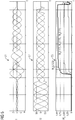
- Figures 3-5 show diagrams for different error cases in which an erroneous loop is determined using the method described above.
- FIG. 3 show typical time profiles of the currents (diagram 31) and voltages (diagram 32) during a single-pole fault (L1E).
- Diagram 33 shows the course of the loop-specific probability values W s for all possible loops.
- the current in the faulted phase increases (point 34 in diagram 31).
- the voltage of the faulty phase breaks down (point 35 in diagram 32).
- protection criteria eg, current height criterion, voltage height criterion, delta current height criterion, delta voltage height criterion, impedance criterion, etc.
- the algorithm for detecting the type of error "error loop” responds quickly and, taking into account all protection criteria-specific probability values in a short time, the faulty loop L1E (point 36 in diagram 33), which has a loop-specific probability value of over 85%.
- the other loops are usually less than 10%.
- FIG. 5 shows typical time histories of the currents (diagram 41) and voltages (diagram 42) during a two-pole earth-fault (L23 with earth contribution).
- Diagram 43 shows the course of the loop-specific probability values W s for all possible loops.
- protection criterion-specific probability values for the individual possible loops can be determined, from which in turn a respective loop-specific probability value is determined.
- the algorithm for detecting the type of error "faulty loop” reacts quickly and safely.
- Three loops (L23, L2E, L3E) with loop-specific probability values above 75% quality are determined (location 46 in diagram 43), which is the correct response for this type of error.
- FIG. 5 shows typical time profiles of the currents (diagram 51) and voltages (diagram 52) during a three-pole fault (L123).
- Diagram 53 shows the course of the loop-specific probability values W s for all possible loops. In this case, a high loop-specific probability value W s (L123) is calculated for the three-pole loop L123. Since it is a three-pole error, the loop-specific probability values of the two-pole loops W s (L12), W s (L23), W s (L31) are also relatively high. The single-pole loops, on the other hand, are rated lower.
- FIG. 2 The block diagram shown generally shows the procedure for generating an error signal indicating an error type.
- error type "error direction”
- the special feature must also be taken into account that the respective protection criterion can provide a total of three results (probability for forward, backward, undirected), whereas only one result (probability of errors in the relevant loop) is determined for the error-prone loop error type.
- the weighting factors G1 ... Gn have hitherto been predefined and were derived, for example, from empirical values that have been made with similar network configurations.
- An example of a fixed specification of weighting factors for 11 different protection criteria is shown schematically in FIG. 6 shown.
- Such fixed predetermined weighting factors usually represent the best possible compromise for a variety of operating states of the power grid, but are not optimally adapted to each specific operating condition.
- the weighting factors are now adjusted depending on a current operating state of the power grid.
- the indication of the type of error e.g., selection of the errored loop
- the basic considerations will be illustrated by means of an example.
- FIG. 7 by way of example a power supply unit 70 of a power supply network, not otherwise shown. Between two bus bars 71a, 71b are three lines 72a, 72b, 72c. The busbars 71a, b are each fed by two different sources 73, which are indicated here merely by way of example. Switching devices 74a-g serve to interrupt the flow of current at selected locations in the illustrated power supply 70.
- the line 72a is to be considered in more detail, which is monitored by two protective devices 75a and 75b.
- the protective devices may be, for example, protection devices of the patent application's SIPROTEC family.
- the switching devices 74a-g Through various switching operations with respect to the switching devices 74a-g, the feed conditions of the line 72a and thus the current operating state of the power supply network can be changed in the indicated by the line 76 protection zone.
- the magnetic coupling of the line 72a varies with the parallel lines 72b and 72c, which also affects the current operating state.
- weighting factors G1 ... Gn result for the individual criteria.
- the diagram shows a set of weighting factors G1 ... Gn for the weighting of the various protection criteria S1-S11 for the four operating states indicated in the table presented above.
- a first line 81 represents the set of weighting factors for the first operating state (weak infeed, weak coupling) mentioned in the table
- a second line 82 the set of weighting factors for the second operating state (weak infeed, strong coupling) mentioned in the table
- a third line 83 represents the set of weighting factors for the third operating state mentioned in the table
- a fourth line 84 the set of weighting factors for the fourth operating state mentioned in the table.
- the operating state can be determined, for example, based on switching states of switching devices and / or measured values of electrical measured variables. Based on a recognized operating state, the weighting factors are then determined in a subsequent step in such a way that a possible optimal detection of the type of error of an error can take place.
- the adaptation of the weighting factors for example, purely locally in the protective device (eg protective device 12 in FIG. 1 ) occur.
- the switching position of the at least one switching device and / or the measured values of the at least one electrical measured variable are detected by the protective device 12 and the current operating state is determined by means of the evaluation device 14 of the protective device 12.
- precalculated tables of weighting factors for the most probable operating states of the energy supply network can be stored in a data storage device of the protective device 12. Switching between the individual sets of weighting factors may in this case be e.g. by recording local operational readings and / or switch positions. A selection algorithm then uses the table entry of weighting factors that has been determined for an operating state that is most similar to the current operating state.
- the adaptation of the weighting factors can also be effected by an interaction of the protective device 12 with a superordinate control center device.
- measured values and switch positions are displayed at different locations in the power grid have been recorded, analyzed with a control center device of the power supply network and calculated by an optimization algorithm, the weighting factors as a function of the changing current operating state.
- the adjusted weighting factors are transmitted via a communication link from the control center device to the protective device and taken over there for ongoing operation.
- the protective device can then be operated optimally for the prevailing network situation.
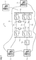
- FIG. 9 This is exemplary in FIG. 9 shown.
- a power supply network 90 is shown schematically.
- a power supply 91 is marked as a protection zone, in which associated with FIG. 2 described algorithm for detecting a type of error is performed.
- the power supply 91 are associated with the plurality of protective devices, of which in the FIG. 9 For the sake of clarity, only the protective device 92 is shown.
- the protective devices perform conventional protection algorithms, eg a distance protection algorithm, for monitoring the power supply unit 91. For this they take measured values M of electrical measured variables / eg current, voltage) at suitable measuring points of the energy supply network 90 and process them with the protection algorithm.
- the measured values M and information about the switching positions SW of existing in the power supply load and circuit breakers via any communication connection (eg exchanged via the IEC61850 data telegrams) to a control center device 93, such as a network control center, transmitted.
- a control center device 93 such as a network control center
- the protection devices have the above-mentioned multi-criteria algorithm for detecting the type of fault, in which the influence of the individual protection criteria on the overall result can be controlled by weighting factors.
- these weighting factors adaptively and dynamically adapted to a current operating state can be.
- the protective devices of the control center device transmit a request that an adaptation be necessary.
- the cause of this request can be, for example, an increasing load flow or changes in the switching positions, which can be detected locally by the respective protective device in a simple manner on the basis of detected measured values and switching positions.
- the control center device 93 also performs an observation of the energy supply network 90, in particular also of the power supply 91, by means of the measured values and switching positions transmitted by a plurality of protective devices.
- the control center device 93 has an overall view of the state of the energy supply network 90.
- the control center device 93 can carry out customary monitoring methods as used in network and station control stations.
- control center device 93 can independently decide in this context on the necessity of adjusting the weighting factors. This can be done, for example, on the basis of the measured values and switching positions transmitted by the protective devices of the power supply 91, but also on the basis of known timetables which are used by the control center device for operating the energy supply network.
- control center device may also have information that is not known to the protective devices in the power supply 91, for example because they have been detected outside of the power supply 91 or because they have been detected with measuring devices in the power supply 91, not with the protective devices, but only communicate with the control center facility. This information may include relevant state changes of the power grid that may affect the behavior of the multi-criteria algorithm. In the event of a change in the current operating state of the power grid, an adjustment must be made the weighting factors are used so that the protective devices can perform their protective tasks optimally.
- the power supply 91 is imaged on the control center device 93 by a mathematical network model 94 in which simulations can be carried out on the basis of the measured values M and the switching positions SW.
- the external connection nodes in the network model which represent a transition between the power supply unit 91 and the rest of the energy supply network, can be imaged by the load flow-driving current or voltage sources.
- short circuits are modeled in the network model.
- the simulated measured values resulting from the simulation are applied to replicas of the protection criteria implemented in the protective devices and their reaction is determined.
- a replica of the multi-criteria algorithm which is also present on the protective devices, is implemented in the control center.
- the answers sought for the individual protection criteria are automatically provided.
- the reactions of the respective protection criteria could be determined individually or in groups by simulation with any other simulation environments.
- the responses W of the individual protection criteria to the simulated short circuits corresponding to the probability values W k are then transmitted to an optimization algorithm 95, which is also performed on the control center 93.
- the aim of the optimization algorithm is to adapt the weighting factors of the individual protection criteria in such a way that the protection criteria that are reliable in the respective current operating state are increasingly included in the determination of the type of fault, whereas the unreliable protection criteria are suppressed.
- the optimization can be carried out as follows:
- the simulated short circuits result in a large number of data, from which the weighting factors are determined by means of a mathematical optimization.
- the protection criteria provide probability values W for the three single-pole loops (L1E, L2E, L3E), the three two-pole loops (L12, L23, L31) and the one three-pole loop (L123).
- W probability values W for the three single-pole loops (L1E, L2E, L3E), the three two-pole loops (L12, L23, L31) and the one three-pole loop (L123).
- W i, j denote the probability values of the protection criteria j for the possible error loops i and G j the weighting factors.
- Q j are the results of the equation system to be optimized. In this case, the results Q j of the error loops maximizes, whereas the results Q j of the error-free loops must be minimized.
- the matrix of the probability values W i, j in the above-described system of equations contains seven lines per simulated short circuit, thus resulting in overdetermination for the equation system, since a large number of equations must be optimized by the variation of only eleven parameters.
- Simple optimization approaches reach their limits here, as they tend to trivial solutions.
- This equation contains the results converted from the original matrix A in regularized form.
- a reg is now a quadratic matrix, so the problem can be solved much better with the help of the conjugate gradient method than the original problem.
- the advantage here is that this is a purposeful process and thus provides significantly better, non-trivial results.
- Measured values and / or switching positions of the real energy supply network are transmitted to the control device.
- incidents in particular short circuits, are simulated using the current measured values and / or switching positions. The reaction of the individual protection criteria to the simulated incidents is considered.
- the probability values resulting from the simulation are fed to an optimization algorithm.
- the optimization problem is transformed into a replacement problem and then optimized.
- the optimization determines weighting factors that give greater weight to those protection criteria that correctly identified the simulated accident, and less weight those protection criteria that have detected the simulated accident more or less correctly.
- the determined weighting factors G are subsequently transmitted from the control center device to the individual protective devices and implemented there for ongoing operation.
- the fault detection by the protection devices can adaptively adapt to the current operating state of the power grid.
- An algorithm has been described above, with which an error signal indicating a type of error can be generated particularly advantageously.
- a particular advantage is that several protection criteria are evaluated in parallel to decide on the type of error and the results of all evaluations are included in the generation of the error signal.
- the algorithm described can be adapted very flexibly to new network conditions and network constellations since it provides for an adaptive adaptation of the weighting factors of the individual protection criteria.
- the algorithm can be adapted very flexibly to the respective energy supply network. As bidirectional power transmission in power grids increases, the network configuration and short circuit line of the grid will change more frequently.
- the algorithm described represents a future-oriented smart grid application in the context of a digital substation. It ensures improved stability in loop selection and direction detection, which provides the basis for the correct functioning of any protection algorithm, e.g. a distance protection algorithm.
Landscapes
- Emergency Protection Circuit Devices (AREA)
- Remote Monitoring And Control Of Power-Distribution Networks (AREA)
Priority Applications (1)
| Application Number | Priority Date | Filing Date | Title |
|---|---|---|---|
| EP17160528.0A EP3376622B1 (fr) | 2017-03-13 | 2017-03-13 | Procédé, système et dispositif de protection destinés à produire un signal d'erreur indiquant un type d'erreur dans un réseau d'alimentation électrique multiphases |
Applications Claiming Priority (1)
| Application Number | Priority Date | Filing Date | Title |
|---|---|---|---|
| EP17160528.0A EP3376622B1 (fr) | 2017-03-13 | 2017-03-13 | Procédé, système et dispositif de protection destinés à produire un signal d'erreur indiquant un type d'erreur dans un réseau d'alimentation électrique multiphases |
Publications (2)
| Publication Number | Publication Date |
|---|---|
| EP3376622A1 true EP3376622A1 (fr) | 2018-09-19 |
| EP3376622B1 EP3376622B1 (fr) | 2021-11-24 |
Family
ID=58398007
Family Applications (1)
| Application Number | Title | Priority Date | Filing Date |
|---|---|---|---|
| EP17160528.0A Active EP3376622B1 (fr) | 2017-03-13 | 2017-03-13 | Procédé, système et dispositif de protection destinés à produire un signal d'erreur indiquant un type d'erreur dans un réseau d'alimentation électrique multiphases |
Country Status (1)
| Country | Link |
|---|---|
| EP (1) | EP3376622B1 (fr) |
Cited By (3)
| Publication number | Priority date | Publication date | Assignee | Title |
|---|---|---|---|---|
| CN113159641A (zh) * | 2021-05-17 | 2021-07-23 | 广东电网有限责任公司 | 基于匹配度因子的停电处置预案、系统、终端和存储介质 |
| CN113822580A (zh) * | 2021-09-24 | 2021-12-21 | 华润电力技术研究院有限公司 | 一种设备工况评估方法以及相关设备 |
| CN116040431A (zh) * | 2023-02-02 | 2023-05-02 | 日立楼宇技术(广州)有限公司 | 一种安全回路的检测方法、装置、设备及存储介质 |
Citations (4)
| Publication number | Priority date | Publication date | Assignee | Title |
|---|---|---|---|---|
| US4812995A (en) * | 1987-05-19 | 1989-03-14 | Girgis Adly A | Adaptive Kalman Filtering in fault classification |
| EP2304857B1 (fr) | 2008-07-07 | 2013-09-04 | ABB Research Ltd. | Procédé et appareil de déblocage d oscillations de puissance rapide destinés à la protection à distance, dans un système électrique |
| RU2548666C1 (ru) * | 2014-02-25 | 2015-04-20 | Александр Леонидович Куликов | Способ дистанционной защиты линии электропередачи |
| WO2016091334A1 (fr) | 2014-12-12 | 2016-06-16 | Siemens Aktiengesellschaft | Procédé et dispositif de protection pour générer un signal de défaut indiquant un type de défaut d'un réseau d'alimentation en énergie électrique polyphasée |
-
2017
- 2017-03-13 EP EP17160528.0A patent/EP3376622B1/fr active Active
Patent Citations (4)
| Publication number | Priority date | Publication date | Assignee | Title |
|---|---|---|---|---|
| US4812995A (en) * | 1987-05-19 | 1989-03-14 | Girgis Adly A | Adaptive Kalman Filtering in fault classification |
| EP2304857B1 (fr) | 2008-07-07 | 2013-09-04 | ABB Research Ltd. | Procédé et appareil de déblocage d oscillations de puissance rapide destinés à la protection à distance, dans un système électrique |
| RU2548666C1 (ru) * | 2014-02-25 | 2015-04-20 | Александр Леонидович Куликов | Способ дистанционной защиты линии электропередачи |
| WO2016091334A1 (fr) | 2014-12-12 | 2016-06-16 | Siemens Aktiengesellschaft | Procédé et dispositif de protection pour générer un signal de défaut indiquant un type de défaut d'un réseau d'alimentation en énergie électrique polyphasée |
Cited By (4)
| Publication number | Priority date | Publication date | Assignee | Title |
|---|---|---|---|---|
| CN113159641A (zh) * | 2021-05-17 | 2021-07-23 | 广东电网有限责任公司 | 基于匹配度因子的停电处置预案、系统、终端和存储介质 |
| CN113159641B (zh) * | 2021-05-17 | 2023-01-20 | 广东电网有限责任公司 | 基于匹配度因子的停电处置预案、系统、终端和存储介质 |
| CN113822580A (zh) * | 2021-09-24 | 2021-12-21 | 华润电力技术研究院有限公司 | 一种设备工况评估方法以及相关设备 |
| CN116040431A (zh) * | 2023-02-02 | 2023-05-02 | 日立楼宇技术(广州)有限公司 | 一种安全回路的检测方法、装置、设备及存储介质 |
Also Published As
| Publication number | Publication date |
|---|---|
| EP3376622B1 (fr) | 2021-11-24 |
Similar Documents
| Publication | Publication Date | Title |
|---|---|---|
| EP2605352B1 (fr) | Protection de lignes parallèles d'un réseau d'alimentation en énergie électrique | |
| EP2476002B1 (fr) | Identification de défauts dans des réseaux d'alimentation en énergie présentant un point neutre non relié à la terre ou une disparition du point neutre | |
| DE69414605T2 (de) | Differentialschutzeinrichtung für einen leistungstransformator | |
| EP3198698B1 (fr) | Procédé de protection de différentiel et appareil de protection de différentiel permettant de mettre en oeuvre un procédé de protection de différentiel | |
| EP2719043B1 (fr) | Détection et localisation de défauts dans une ligne de distribution d'énergie alimentée d'un seul côté | |
| EP2845286B1 (fr) | Détection de défauts dans des réseaux d'alimentation en énergie | |
| EP2145367B1 (fr) | Procédé pour déterminer une valeur de réglage donnant l'impédance de terre et dispositif de mesure | |
| EP2301128B1 (fr) | Procédé de production d'un signal d'erreur et appareil électrique de protection | |
| DE102018122248A1 (de) | Verfahren und Systeme zur Erdschlusserfassung in einem Leistungsverteilungssystem | |
| EP3207610B1 (fr) | Procédé et dispositif de protection pour générer un signal de défaut indiquant un type de défaut d'un réseau d'alimentation en énergie électrique polyphasée | |
| EP3876373A1 (fr) | Procédé de protection différentielle, dispositif de protection différentielle et système de protection différentielle | |
| EP3376622B1 (fr) | Procédé, système et dispositif de protection destinés à produire un signal d'erreur indiquant un type d'erreur dans un réseau d'alimentation électrique multiphases | |
| EP3108554B1 (fr) | Procédé de protection de différentiel et dispositif de protection de différentiel | |
| DE102013109939A1 (de) | Energieverteilungssysteme und Verfahren zum Betrieb eines Energieverteilungssystems | |
| EP4012864B1 (fr) | Dispositif de protection et procédé de surveillance d'un réseau d'alimentation électrique | |
| EP3916939B1 (fr) | Procédé pour une protection de conduites et agencement de protection | |
| EP2289144B1 (fr) | Procédé de production d'un signal pendulaire et appareil électrique de protection ou de mesure avec un dispositif de détection des oscillations pendulaires | |
| EP2171488B1 (fr) | Procédé de localisation d'un défaut à la terre selon le principe de la protection de distance et appareil de protection de distance électrique | |
| EP2870487B1 (fr) | Détection d'une direction de défaut dans des réseaux d'alimentation en énergie moyenne tension | |
| DE4026799A1 (de) | Verfahren zur selektiven erfassung von fehlern der leiter in hoch- und hoechstspannungsnetzen | |
| EP3964847A1 (fr) | Procédé de détermination de la valeur de compensation, en particulier pour un procédé de protection à distance | |
| DE2456073C3 (de) | Schutzanordnung fur Drehstromubertragungssysteme | |
| EP2908397A1 (fr) | Procédé de protection d'un réseau d'alimentation électrique | |
| EP2057726B1 (fr) | Procédé et système de protection différentielle | |
| EP1322019B1 (fr) | Procédé et dispositif de protection de distance |
Legal Events
| Date | Code | Title | Description |
|---|---|---|---|
| PUAI | Public reference made under article 153(3) epc to a published international application that has entered the european phase |
Free format text: ORIGINAL CODE: 0009012 |
|
| STAA | Information on the status of an ep patent application or granted ep patent |
Free format text: STATUS: THE APPLICATION HAS BEEN PUBLISHED |
|
| AK | Designated contracting states |
Kind code of ref document: A1 Designated state(s): AL AT BE BG CH CY CZ DE DK EE ES FI FR GB GR HR HU IE IS IT LI LT LU LV MC MK MT NL NO PL PT RO RS SE SI SK SM TR |
|
| AX | Request for extension of the european patent |
Extension state: BA ME |
|
| STAA | Information on the status of an ep patent application or granted ep patent |
Free format text: STATUS: REQUEST FOR EXAMINATION WAS MADE |
|
| 17P | Request for examination filed |
Effective date: 20190218 |
|
| RBV | Designated contracting states (corrected) |
Designated state(s): AL AT BE BG CH CY CZ DE DK EE ES FI FR GB GR HR HU IE IS IT LI LT LU LV MC MK MT NL NO PL PT RO RS SE SI SK SM TR |
|
| GRAP | Despatch of communication of intention to grant a patent |
Free format text: ORIGINAL CODE: EPIDOSNIGR1 |
|
| STAA | Information on the status of an ep patent application or granted ep patent |
Free format text: STATUS: GRANT OF PATENT IS INTENDED |
|
| INTG | Intention to grant announced |
Effective date: 20210702 |
|
| GRAS | Grant fee paid |
Free format text: ORIGINAL CODE: EPIDOSNIGR3 |
|
| GRAA | (expected) grant |
Free format text: ORIGINAL CODE: 0009210 |
|
| STAA | Information on the status of an ep patent application or granted ep patent |
Free format text: STATUS: THE PATENT HAS BEEN GRANTED |
|
| AK | Designated contracting states |
Kind code of ref document: B1 Designated state(s): AL AT BE BG CH CY CZ DE DK EE ES FI FR GB GR HR HU IE IS IT LI LT LU LV MC MK MT NL NO PL PT RO RS SE SI SK SM TR |
|
| REG | Reference to a national code |
Ref country code: GB Ref legal event code: FG4D Free format text: NOT ENGLISH |
|
| REG | Reference to a national code |
Ref country code: AT Ref legal event code: REF Ref document number: 1450591 Country of ref document: AT Kind code of ref document: T Effective date: 20211215 |
|
| REG | Reference to a national code |
Ref country code: DE Ref legal event code: R096 Ref document number: 502017012077 Country of ref document: DE |
|
| REG | Reference to a national code |
Ref country code: IE Ref legal event code: FG4D Free format text: LANGUAGE OF EP DOCUMENT: GERMAN |
|
| REG | Reference to a national code |
Ref country code: LT Ref legal event code: MG9D |
|
| REG | Reference to a national code |
Ref country code: NL Ref legal event code: MP Effective date: 20211124 |
|
| PG25 | Lapsed in a contracting state [announced via postgrant information from national office to epo] |
Ref country code: RS Free format text: LAPSE BECAUSE OF FAILURE TO SUBMIT A TRANSLATION OF THE DESCRIPTION OR TO PAY THE FEE WITHIN THE PRESCRIBED TIME-LIMIT Effective date: 20211124 Ref country code: LT Free format text: LAPSE BECAUSE OF FAILURE TO SUBMIT A TRANSLATION OF THE DESCRIPTION OR TO PAY THE FEE WITHIN THE PRESCRIBED TIME-LIMIT Effective date: 20211124 Ref country code: FI Free format text: LAPSE BECAUSE OF FAILURE TO SUBMIT A TRANSLATION OF THE DESCRIPTION OR TO PAY THE FEE WITHIN THE PRESCRIBED TIME-LIMIT Effective date: 20211124 Ref country code: BG Free format text: LAPSE BECAUSE OF FAILURE TO SUBMIT A TRANSLATION OF THE DESCRIPTION OR TO PAY THE FEE WITHIN THE PRESCRIBED TIME-LIMIT Effective date: 20220224 |
|
| PG25 | Lapsed in a contracting state [announced via postgrant information from national office to epo] |
Ref country code: IS Free format text: LAPSE BECAUSE OF FAILURE TO SUBMIT A TRANSLATION OF THE DESCRIPTION OR TO PAY THE FEE WITHIN THE PRESCRIBED TIME-LIMIT Effective date: 20220324 Ref country code: SE Free format text: LAPSE BECAUSE OF FAILURE TO SUBMIT A TRANSLATION OF THE DESCRIPTION OR TO PAY THE FEE WITHIN THE PRESCRIBED TIME-LIMIT Effective date: 20211124 Ref country code: PT Free format text: LAPSE BECAUSE OF FAILURE TO SUBMIT A TRANSLATION OF THE DESCRIPTION OR TO PAY THE FEE WITHIN THE PRESCRIBED TIME-LIMIT Effective date: 20220324 Ref country code: PL Free format text: LAPSE BECAUSE OF FAILURE TO SUBMIT A TRANSLATION OF THE DESCRIPTION OR TO PAY THE FEE WITHIN THE PRESCRIBED TIME-LIMIT Effective date: 20211124 Ref country code: NO Free format text: LAPSE BECAUSE OF FAILURE TO SUBMIT A TRANSLATION OF THE DESCRIPTION OR TO PAY THE FEE WITHIN THE PRESCRIBED TIME-LIMIT Effective date: 20220224 Ref country code: NL Free format text: LAPSE BECAUSE OF FAILURE TO SUBMIT A TRANSLATION OF THE DESCRIPTION OR TO PAY THE FEE WITHIN THE PRESCRIBED TIME-LIMIT Effective date: 20211124 Ref country code: LV Free format text: LAPSE BECAUSE OF FAILURE TO SUBMIT A TRANSLATION OF THE DESCRIPTION OR TO PAY THE FEE WITHIN THE PRESCRIBED TIME-LIMIT Effective date: 20211124 Ref country code: HR Free format text: LAPSE BECAUSE OF FAILURE TO SUBMIT A TRANSLATION OF THE DESCRIPTION OR TO PAY THE FEE WITHIN THE PRESCRIBED TIME-LIMIT Effective date: 20211124 Ref country code: GR Free format text: LAPSE BECAUSE OF FAILURE TO SUBMIT A TRANSLATION OF THE DESCRIPTION OR TO PAY THE FEE WITHIN THE PRESCRIBED TIME-LIMIT Effective date: 20220225 Ref country code: ES Free format text: LAPSE BECAUSE OF FAILURE TO SUBMIT A TRANSLATION OF THE DESCRIPTION OR TO PAY THE FEE WITHIN THE PRESCRIBED TIME-LIMIT Effective date: 20211124 |
|
| PG25 | Lapsed in a contracting state [announced via postgrant information from national office to epo] |
Ref country code: SM Free format text: LAPSE BECAUSE OF FAILURE TO SUBMIT A TRANSLATION OF THE DESCRIPTION OR TO PAY THE FEE WITHIN THE PRESCRIBED TIME-LIMIT Effective date: 20211124 Ref country code: SK Free format text: LAPSE BECAUSE OF FAILURE TO SUBMIT A TRANSLATION OF THE DESCRIPTION OR TO PAY THE FEE WITHIN THE PRESCRIBED TIME-LIMIT Effective date: 20211124 Ref country code: RO Free format text: LAPSE BECAUSE OF FAILURE TO SUBMIT A TRANSLATION OF THE DESCRIPTION OR TO PAY THE FEE WITHIN THE PRESCRIBED TIME-LIMIT Effective date: 20211124 Ref country code: EE Free format text: LAPSE BECAUSE OF FAILURE TO SUBMIT A TRANSLATION OF THE DESCRIPTION OR TO PAY THE FEE WITHIN THE PRESCRIBED TIME-LIMIT Effective date: 20211124 Ref country code: DK Free format text: LAPSE BECAUSE OF FAILURE TO SUBMIT A TRANSLATION OF THE DESCRIPTION OR TO PAY THE FEE WITHIN THE PRESCRIBED TIME-LIMIT Effective date: 20211124 Ref country code: CZ Free format text: LAPSE BECAUSE OF FAILURE TO SUBMIT A TRANSLATION OF THE DESCRIPTION OR TO PAY THE FEE WITHIN THE PRESCRIBED TIME-LIMIT Effective date: 20211124 |
|
| REG | Reference to a national code |
Ref country code: DE Ref legal event code: R097 Ref document number: 502017012077 Country of ref document: DE |
|
| PLBE | No opposition filed within time limit |
Free format text: ORIGINAL CODE: 0009261 |
|
| STAA | Information on the status of an ep patent application or granted ep patent |
Free format text: STATUS: NO OPPOSITION FILED WITHIN TIME LIMIT |
|
| PG25 | Lapsed in a contracting state [announced via postgrant information from national office to epo] |
Ref country code: MC Free format text: LAPSE BECAUSE OF FAILURE TO SUBMIT A TRANSLATION OF THE DESCRIPTION OR TO PAY THE FEE WITHIN THE PRESCRIBED TIME-LIMIT Effective date: 20211124 Ref country code: AL Free format text: LAPSE BECAUSE OF FAILURE TO SUBMIT A TRANSLATION OF THE DESCRIPTION OR TO PAY THE FEE WITHIN THE PRESCRIBED TIME-LIMIT Effective date: 20211124 |
|
| REG | Reference to a national code |
Ref country code: CH Ref legal event code: PL |
|
| 26N | No opposition filed |
Effective date: 20220825 |
|
| PG25 | Lapsed in a contracting state [announced via postgrant information from national office to epo] |
Ref country code: SI Free format text: LAPSE BECAUSE OF FAILURE TO SUBMIT A TRANSLATION OF THE DESCRIPTION OR TO PAY THE FEE WITHIN THE PRESCRIBED TIME-LIMIT Effective date: 20211124 |
|
| REG | Reference to a national code |
Ref country code: BE Ref legal event code: MM Effective date: 20220331 |
|
| PG25 | Lapsed in a contracting state [announced via postgrant information from national office to epo] |
Ref country code: LU Free format text: LAPSE BECAUSE OF NON-PAYMENT OF DUE FEES Effective date: 20220313 Ref country code: LI Free format text: LAPSE BECAUSE OF NON-PAYMENT OF DUE FEES Effective date: 20220331 Ref country code: IE Free format text: LAPSE BECAUSE OF NON-PAYMENT OF DUE FEES Effective date: 20220313 Ref country code: CH Free format text: LAPSE BECAUSE OF NON-PAYMENT OF DUE FEES Effective date: 20220331 |
|
| PG25 | Lapsed in a contracting state [announced via postgrant information from national office to epo] |
Ref country code: BE Free format text: LAPSE BECAUSE OF NON-PAYMENT OF DUE FEES Effective date: 20220331 |
|
| REG | Reference to a national code |
Ref country code: AT Ref legal event code: MM01 Ref document number: 1450591 Country of ref document: AT Kind code of ref document: T Effective date: 20220313 |
|
| PG25 | Lapsed in a contracting state [announced via postgrant information from national office to epo] |
Ref country code: AT Free format text: LAPSE BECAUSE OF NON-PAYMENT OF DUE FEES Effective date: 20220313 |
|
| PG25 | Lapsed in a contracting state [announced via postgrant information from national office to epo] |
Ref country code: HU Free format text: LAPSE BECAUSE OF FAILURE TO SUBMIT A TRANSLATION OF THE DESCRIPTION OR TO PAY THE FEE WITHIN THE PRESCRIBED TIME-LIMIT; INVALID AB INITIO Effective date: 20170313 |
|
| PG25 | Lapsed in a contracting state [announced via postgrant information from national office to epo] |
Ref country code: MK Free format text: LAPSE BECAUSE OF FAILURE TO SUBMIT A TRANSLATION OF THE DESCRIPTION OR TO PAY THE FEE WITHIN THE PRESCRIBED TIME-LIMIT Effective date: 20211124 Ref country code: CY Free format text: LAPSE BECAUSE OF FAILURE TO SUBMIT A TRANSLATION OF THE DESCRIPTION OR TO PAY THE FEE WITHIN THE PRESCRIBED TIME-LIMIT Effective date: 20211124 |
|
| PG25 | Lapsed in a contracting state [announced via postgrant information from national office to epo] |
Ref country code: TR Free format text: LAPSE BECAUSE OF FAILURE TO SUBMIT A TRANSLATION OF THE DESCRIPTION OR TO PAY THE FEE WITHIN THE PRESCRIBED TIME-LIMIT Effective date: 20211124 |
|
| PG25 | Lapsed in a contracting state [announced via postgrant information from national office to epo] |
Ref country code: MT Free format text: LAPSE BECAUSE OF FAILURE TO SUBMIT A TRANSLATION OF THE DESCRIPTION OR TO PAY THE FEE WITHIN THE PRESCRIBED TIME-LIMIT Effective date: 20211124 |
|
| PGFP | Annual fee paid to national office [announced via postgrant information from national office to epo] |
Ref country code: DE Payment date: 20250520 Year of fee payment: 9 |
|
| PGFP | Annual fee paid to national office [announced via postgrant information from national office to epo] |
Ref country code: GB Payment date: 20250403 Year of fee payment: 9 |
|
| PGFP | Annual fee paid to national office [announced via postgrant information from national office to epo] |
Ref country code: IT Payment date: 20260324 Year of fee payment: 10 |
|
| PGFP | Annual fee paid to national office [announced via postgrant information from national office to epo] |
Ref country code: FR Payment date: 20260316 Year of fee payment: 10 |