EP3377167B1 - Mehrweghahn mit mehrfachhaltering - Google Patents
Mehrweghahn mit mehrfachhaltering Download PDFInfo
- Publication number
- EP3377167B1 EP3377167B1 EP16797473.2A EP16797473A EP3377167B1 EP 3377167 B1 EP3377167 B1 EP 3377167B1 EP 16797473 A EP16797473 A EP 16797473A EP 3377167 B1 EP3377167 B1 EP 3377167B1
- Authority
- EP
- European Patent Office
- Prior art keywords
- actuator
- way valve
- valve according
- receptacle
- recesses
- Prior art date
- Legal status (The legal status is an assumption and is not a legal conclusion. Google has not performed a legal analysis and makes no representation as to the accuracy of the status listed.)
- Active
Links
Images


Classifications
-
- A—HUMAN NECESSITIES
- A61—MEDICAL OR VETERINARY SCIENCE; HYGIENE
- A61M—DEVICES FOR INTRODUCING MEDIA INTO, OR ONTO, THE BODY; DEVICES FOR TRANSDUCING BODY MEDIA OR FOR TAKING MEDIA FROM THE BODY; DEVICES FOR PRODUCING OR ENDING SLEEP OR STUPOR
- A61M39/00—Tubes, tube connectors, tube couplings, valves, access sites or the like, specially adapted for medical use
- A61M39/22—Valves or arrangement of valves
- A61M39/223—Multiway valves
-
- F—MECHANICAL ENGINEERING; LIGHTING; HEATING; WEAPONS; BLASTING
- F16—ENGINEERING ELEMENTS AND UNITS; GENERAL MEASURES FOR PRODUCING AND MAINTAINING EFFECTIVE FUNCTIONING OF MACHINES OR INSTALLATIONS; THERMAL INSULATION IN GENERAL
- F16K—VALVES; TAPS; COCKS; ACTUATING-FLOATS; DEVICES FOR VENTING OR AERATING
- F16K11/00—Multiple-way valves, e.g. mixing valves; Pipe fittings incorporating such valves
- F16K11/02—Multiple-way valves, e.g. mixing valves; Pipe fittings incorporating such valves with all movable sealing faces moving as one unit
- F16K11/08—Multiple-way valves, e.g. mixing valves; Pipe fittings incorporating such valves with all movable sealing faces moving as one unit comprising only taps or cocks
- F16K11/085—Multiple-way valves, e.g. mixing valves; Pipe fittings incorporating such valves with all movable sealing faces moving as one unit comprising only taps or cocks with cylindrical plug
- F16K11/0853—Multiple-way valves, e.g. mixing valves; Pipe fittings incorporating such valves with all movable sealing faces moving as one unit comprising only taps or cocks with cylindrical plug having all the connecting conduits situated in a single plane perpendicular to the axis of the plug
-
- F—MECHANICAL ENGINEERING; LIGHTING; HEATING; WEAPONS; BLASTING
- F16—ENGINEERING ELEMENTS AND UNITS; GENERAL MEASURES FOR PRODUCING AND MAINTAINING EFFECTIVE FUNCTIONING OF MACHINES OR INSTALLATIONS; THERMAL INSULATION IN GENERAL
- F16K—VALVES; TAPS; COCKS; ACTUATING-FLOATS; DEVICES FOR VENTING OR AERATING
- F16K27/00—Construction of housing; Use of materials therefor
- F16K27/06—Construction of housing; Use of materials therefor of taps or cocks
- F16K27/065—Construction of housing; Use of materials therefor of taps or cocks with cylindrical plugs
-
- A—HUMAN NECESSITIES
- A61—MEDICAL OR VETERINARY SCIENCE; HYGIENE
- A61M—DEVICES FOR INTRODUCING MEDIA INTO, OR ONTO, THE BODY; DEVICES FOR TRANSDUCING BODY MEDIA OR FOR TAKING MEDIA FROM THE BODY; DEVICES FOR PRODUCING OR ENDING SLEEP OR STUPOR
- A61M39/00—Tubes, tube connectors, tube couplings, valves, access sites or the like, specially adapted for medical use
- A61M39/22—Valves or arrangement of valves
- A61M39/229—Single-way cut-off valves
Definitions
- the present invention relates to a multi-way valve, in particular 2-, 3- and 4-way valves as they are used in particular in medicine.
- Multi-way valves in particular 2-, 3- or 4-way valves are known in the prior art and are used in particular in medicine and medical technology. They are used in particular in the infusion area, in the field of artificial nutrition, in transfusion and in particular for the supply or transfer of various flow media and as so-called "injection equipment” for medical and pharmaceutical equipment.
- the reusable taps are also used in medical systems, which consist of several components. Such systems include, among others, gravity infusions, pumps or pump transfer systems, tube feeding systems, injections, combinations thereof, and the like.
- a multi-way valve can also be assembled by combining it with several multi-way valves to form a so-called multi-way valve bank or "manifold" (multiple manifold).
- reusable taps When it comes to the provision of reusable taps, it is important that there is in particular a predetermined tightness, easy operation and freedom from burring of the components.
- reusable taps are used to feed different media, which among other things have very different viscosities.
- the DE 10 2009 026 172 A1 discloses a reusable tap for use in medicine which shows the combination of the features of the preamble of claim 1.
- the basic housing of the multi-way valve has an actuator which can be rotated about a central axis.
- the US 2005/0245899 A1 discloses a connector for liquid suction and liquid supply applications without the need for additional adapters or rubber sleeves to connect a vacuum tube.
- the US 2005/0252560 A1 discloses a shut-off valve which can be connected to a variety of lines.
- the object of the present invention is to at least partially overcome the disadvantages known in the prior art.
- the above object is achieved by a multi-way valve according to the invention.
- Preferred embodiments of the multi-way valve are the subject of the corresponding subclaims.
- the multi-way valve according to the invention for use in medicine and / or medical technology has a basic housing through which a medium can flow at least in sections and an actuator which is rotatably received in the basic housing about a central axis.
- the multi-way valve according to the invention is characterized in that it has connection points for the inflow and outflow of the medium.
- the basic housing of the multi-way valve according to the invention forms an actuator receptacle, which is characterized in that it has a pin arranged concentrically to the central axis of the basic housing.
- the actuator of the multi-way valve according to the invention essentially has an operating element and one cylindrical section, which receives the pin of the actuator receptacle of the basic housing at least in sections and also has at least one flow opening for fluid connection of at least two connection points.
- the spigot of the base housing of the multi-way valve according to the invention is designed such that it has or provides at least in the area of a connection point of the base housing a counter bearing for the actuator, which together with the actuator forms a sealing surface in the area of at least one connection point.
- the multi-way valve according to the invention is characterized in that the multi-way valve has formations and recesses which are each arranged in a corresponding manner to one another and which together form a joint connection between the actuator and the actuator receptacle and at least two joint connections are provided, with at least one form and / or recess being radially circumferential the inside of the actuator main body or is arranged radially circumferentially on the outside of the cylindrical portion of the actuator receptacle.
- medium is understood to mean all types of fluids, in particular liquids, such as, for example, aqueous liquids, blood, porridge, etc. and also gases.
- the basic housing in the sense of the present invention is understood to mean a component of the multi-way valve which has the housing with the connection points and the actuator receptacle, the latter being understood to mean the area of the basic housing which serves to receive the actuator.
- An actuator in the sense of the present invention is understood to mean a so-called “plug" which closes at least one flow opening.
- the control element in the sense of the present invention is an element firmly connected to the actuator, such as a tap, with which the actuator can be rotated about the central axis. This can have one or more, usually two, three or four adjusting levers.
- Counterbearing in the sense of the present invention is understood to mean an area of the actuator receptacle which absorbs the pressure on the actuator, in particular when it is closed, or counteracts deformation of the actuator under the pressure of the medium.
- the cutouts and the formations are each in pairs in a sequence of two cutouts and then of two formations or vice versa in a sequence of two formations and then of two recesses (ie in the pattern 2 + 2) on the actuator or on the actuator receptacle each corresponding to each other.
- the recesses are in pairs and the formations are individual in a sequence of two recesses and then one formation or in a sequence one formation and then two recesses or in a sequence one formation and subsequently two Recesses and subsequent shaping (ie in the pattern 2 + 1, 1 + 2 or 1 + 2 + 1) on the actuator or on the actuator receptacle are arranged corresponding to each other.
- the formations are in pairs and the cutouts are individual in a sequence of two formations and then a cutout or in a sequence of a cutout and then two cutouts or in a sequence of a cutout and then two cutouts and subsequently a cutout (ie in the pattern 2 + 1, 1 + 2 or 1 + 2 + 1) on the actuator or on the actuator receptacle each corresponding to each other.
- the recesses are in groups of three and the formations are individual in a sequence of three recesses and then a formation or in a sequence of a formation and then three recesses (i.e.
- the formations in groups of three and the cutouts are individually in a sequence of three formations and then a cutout or in a sequence of a cutout and then three cutouts (ie in the pattern 3 + 1 or 1 + 3) arranged on the actuator or on the actuator receptacle corresponding to each other.
- the arrangement of the cutouts and shapes of the aforementioned preferred embodiments in the sense of a labyrinth seal achieves not only improved mechanical fixation but also better sealing of the components arranged.
- all the cutouts are arranged on the actuator or all the formations on the actuator receptacle, or according to a further preferred embodiment, the cutouts are and the formations alternately arranged on the actuator or on the actuator receptacle corresponding to each other.
- the diameter of the recesses or the diameter of the formations in the actuator receptacle is gradually smaller in the direction of the interior of the actuator receptacle, such that the innermost recess or innermost formation has the smallest diameter of the existing recesses or formations and the diameter of each additionally Existing recess or shape then gradually increases in the direction of the surface of the actuator receptacle, so that the recess or shape located on the outermost edge is the largest diameter of the existing recesses or shapes.
- the diameter of the recesses or the diameter of the formations in the actuator is gradually smaller in the direction of the cylindrical section of the actuator, such that the innermost recess or innermost formation has the smallest diameter of the existing recesses or formations and the diameter each additional recess or shape then gradually increases in the direction of the control element of the actuator, so that the recess or shape closest to the control element has the largest diameter of the existing recesses or shape.
- This gradual design enables the recesses and corresponding formations of the outer and inner joint connections to engage in a form-fitting manner and only in the intended joint connection positions, i.e.
- the basic housing has two, three or four connection points.
- the medium flowing through the reusable tap is a liquid, in particular selected from a group which contains injection solutions, infusion solutions, nutrient solutions (including nutritional porridge), blood, plasma and combinations thereof and the like.
- the liquid flowing through the reusable tap has a viscosity which is 0.7 mPas -1 and 10 6 mPas -1 , preferably between 1 mPas -1 and 10 5 mPas - 1 , and particularly preferably about 10 2 mPa ⁇ s -1 .
- the pin of the basic housing is at least partially conical.
- conical and non-conical and / or conical sections with different cone angles are carried out in a stepped sequence.
- the cone angle according to the present situation is understood as a deviation from the central axis;
- positive and negative angles are understood as cone angles.
- the pin has an alternating sequence of positive and negative cone angles.
- the pin has, in particular conical sections, offset inwards or outwards relative to the central axis.
- the inside of the cylindrical section is at least partially conical and in particular is essentially adapted to the conical shape of the pin.
- the flow openings of the actuator are designed in the form of a gate, in particular such that the flow opening is open at the end of the cylindrical section of the actuator.
- the flow opening in particular is preferably adapted in size as a function of the fluid to be used, a combination of the shape of the counter bearing, such as, for example, conical and rectangular, also being taken into account.
- the number of flow openings of the actuator corresponds to the number of connection points on the basic housing.
- an embodiment with two connection points has two flow openings.
- the actuator has fewer passage openings than there are connection points on the basic housing, at least and in particular two passage openings or passage openings designed as gates being provided.
- each joint connection has a radially circumferential sealing section and / or a positioning section.
- the at least two joint connections between the actuator and the basic housing of the actuator receptacle are designed such that the connections between the two parts achieve a tightness of preferably greater than 3 bar, particularly preferably greater than 8 bar and most preferably greater than 10 bar , A tightness in the range from greater than approximately 3 bar to greater than approximately 8 bar is preferably achieved.
- multi-way valve according to the invention enables the multi-way valve according to the invention to be used without leakage even for viscous fluids such as food porridge (e.g. for tube feeding systems) whose use, due to the higher medium viscosity, causes higher pressures that attack the joint connections of the multi-way valve.
- viscous fluids such as food porridge (e.g. for tube feeding systems) whose use, due to the higher medium viscosity, causes higher pressures that attack the joint connections of the multi-way valve.
- the formations on the actuator or on the actuator receptacle have a semicircular shape and the shape of the corresponding recesses on the actuator receptacle or on the actuator are correspondingly adapted to the form-fitting reception of the corresponding semicircular shape and formation of the respective joint connection ,
- the cylindrical section of the actuator is formed at least in sections from solid material.
- the cylindrical section of the actuator is formed from solid material in the region of the joint connection.
- At least the housing and / or the actuator is at least partially made of a material which is selected from a group which, in addition to copolyesters, comprises other materials such as, for example, thermosetting and thermoplastic plastics and in particular polyphenylene sulfide, polypropylene, Poly-1-butene, polyvinyl chloride, polyvinylidene chloride, polymethyl methacrylate, polyacrylonitrile, polystyrene, polysulfone, polyacetal, polyvinyl alcohol, polyvinyl acetate, ionomers, fluoroplastic, polyethylene, polyamide, in particular a partially aromatic polyamide, polycarbonate, polyester, copolyester, polyphenylene oxide, polysulfonone , Polyurethane, and chlorinated polyether, cellulose nitrate, cellulose acetate, cellulose ether, phenol resin, urea resin, thiourea resin,
- the reusable tap according to the invention is characterized in that at least the surfaces of the connection system that come into contact with the fluid, in particular the inner surfaces of the reusable tap, are made at least in sections from a material which has antiseptic and / or antimicrobial properties.
- Such antimicrobial or antiseptic materials are, for example, materials such as highly porous silver, ion-free silver, silver compounds and in particular microsilver, metal ion-releasing compounds, combinations thereof and the like. These are preferably arranged in the area of the corresponding surfaces, and according to a further particularly preferred embodiment, the corresponding materials are also incorporated in the plastic from which the multi-way valve or its components are made.
- a highly porous silver which is preferably also produced essentially ion-free, can be mixed into the plastic, the components of the multi-way valve then being produced therefrom at least in sections become.
- an amorphous copolyester is used for producing the reusable valve for medicine and medical technology and its use in particular for infusion or transfusion hoses, multi-way valves, multiple distributors, injection equipment such as needles, accesses or the like and combinations thereof.
- the system is characterized in that at least some of the surfaces of the connection system that come into contact with the fluid are made of an amorphous copolyester.
- materials which contain no plasticizers are used at least in part for the production of the connection system according to the invention.
- the present invention also includes the use of the multi-way valve according to the invention in medicine and medical technology, in particular for the supply and transfer of various flow media, in particular for gravity infusion, for pump transfer systems, tube feeding systems, injections and combinations thereof and the like.
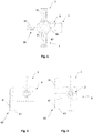
- FIG. 1 shows the basic housing 8 with three connection points 1, 2, 3.
- the actuator 60 has an operating element 61 in the form of a tap with three adjusting levers, which is firmly connected to a cylindrical section 62 (not shown).
- the cylindrical section 62 is arranged concentrically about a central axis 6 (not shown).
- Gate-shaped through openings 82 (gates) are formed on the end of the cylindrical section 62 opposite the control element.
- the embodiment shown here shows an actuator 60, in which only two passages 82 (gates) are provided in the cylindrical section 62, which are in particular arranged at an angle of 90 ° to one another. According to this arrangement, depending on the circuit, connections 1 and 2 or 2 and 3 are fluid-connected. A connection between connection 3 and 1 is not possible.
- the Figures 4 to 6 each show a top view of differently designed multi-way taps, in which in particular the control elements 61 ', 61 ", 61"''are designed differently Figur4 a three-armed control element 61 ', Figur5 a two-armed control element 61 "and Figure 6 a one-armed control element, as can be used in particular in combination with differently designed basic housings 8.
- the arrows 81 attached to the control element also serve for easier orientation when using the reusable taps in practice in order to schematically indicate the direction of flow of the fluid.
- the embodiment according to Figure 7 shows a cross section of the basic housing 8 (shown with coarse hatching) with two recesses 9 running radially around the central axis 6 on the inside of the actuator receptacle 7, each recess 9 being designed such that it has different depths.
- a pin 4 is arranged in the actuator receptacle 7 about a central axis 6.
- the connection point 2 is connected to the actuator receptacle, the passage opening 2 'being formed.
- the diameter of the inner recess 9 in this embodiment has a smaller diameter than the outer one Recess 9 and both cutouts 9 have a partially round shape of the formations 69 of the push-fit actuator 60 (not shown; see, however Figure 8 ) adapted shape to ensure a positive fit of the joint connections during assembly of the multi-way valve according to the invention and thus an increased tightness of the multi-way valve.
- FIG. 8 shows Figure 8 the connection of the base housing 8 (shown with fine-line hatching) in the direction of the AA section line with the actuator 60 corresponding to the Figure 7 as an embodiment of the multi-way valve according to the invention.
- the actuator 60 is pressed into the actuator receptacle 7 of the basic housing up to a predetermined insertion depth X.
- the two semicircular formations 69 of the cylindrical section 62 of the actuator 60 engage positively in the two recesses 9 on the inside of the actuator receptacle 7 of the basic housing 8.
- the cylindrical section 62 (shown with rough hatching) of the actuator 60 encompasses a central one Axle 6 arranged pin 4 of the actuator receptacle 7 and thus forms a counter bearing for the actuator 60.
- the flow of the medium in the open state of the multi-way valve takes place from one of the connection points 1, 3 through the associated passage opening of the basic housing 1 ', 3' through a gate-shaped passage opening 63 of the actuator 60 via a free space 71 between the actuator 60 and the bottom 72 of the actuator receptacle 7 to another passage opening 63 of the actuator and through the respective other passage opening 1 ', 3' of the basic housing from the respective different connection point 1, 3 on the basic housing.
- the tightness in the upper area is achieved by a defined press-in depth of the actuator 60 in the joining edge. In the interior of the basic housing 8, the tightness to the corresponding passage openings 1, 2, 3 via the conical counter bearing, formed by the pin 4, is ensured.
Landscapes
- Engineering & Computer Science (AREA)
- General Engineering & Computer Science (AREA)
- Health & Medical Sciences (AREA)
- Heart & Thoracic Surgery (AREA)
- Mechanical Engineering (AREA)
- Anesthesiology (AREA)
- Hematology (AREA)
- Life Sciences & Earth Sciences (AREA)
- Animal Behavior & Ethology (AREA)
- General Health & Medical Sciences (AREA)
- Public Health (AREA)
- Veterinary Medicine (AREA)
- Biomedical Technology (AREA)
- Pulmonology (AREA)
- Infusion, Injection, And Reservoir Apparatuses (AREA)
- Multiple-Way Valves (AREA)
Description
- Die vorliegende Erfindung betrifft einen Mehrweghahn, insbesondere 2-,3- und 4-Weghähne wie sie insbesondere in der Medizin eingesetzt werden.
- Mehrweghähne insbesondere 2-,3- oder4-Weghähne sind im Stand der Technik bekannt und werden insbesondere in der Medizin und Medizintechnik eingesetzt. Hierbei werden sie insbesondere im Infusionsbereich, dem Bereich der künstlichen Ernährung, bei derTransfusion und insbesondere für die Zu- bzw. Überleitung von verschiedenen Durchflussmedien und als sogenanntes "Injektions-Equipment" für die medizinische und pharmazeutische Ausrüstung verwendet. Die Mehrweghähne werden ferner auch in medizinischen Systemen verwendet, welche unter anderem aus mehreren Komponenten bestehen. Solche Systeme umfassen unter anderem Schwerkraftinfusionen, Pumpen oder Pumpüberleitungssysteme, Sondennahrungssysteme, Injektionen, Kombinationen hiervon und dergleichen.
- Ein Mehrweghahn kann ferner durch die Kombination mit mehreren Mehrweghähnen zu einer sog. Mehrwegehahnbank oder "Manifold" (Mehrfachverteiler) montiert werden.
- Bei der Bereitstellung von Mehrweghähnen ist von Bedeutung, dass insbesondere eine vorgegebene Dichtheit, eine leichte Bedienungsanwendung und eine Gratfreiheit der Bauteile gegeben ist. Insbesondere ist hierbei zu beachten, dass Mehrweghähne zur Zuführung unterschiedlicher Medien verwendet werden, welche unter anderem sehr unterschiedliche Viskositäten aufweisen.
- Im Stand der Technik ist beispielsweise die
US 6,237,628 B1 bekannt, welche die Konstruktion eines Wasserablassventiles zum Ablassen von angesammeltem Wasser aus dem Inneren eines Kraftstofffilters, der mit einem Wasserabscheidevermögen ausgeführt ist, offenbart. - Die
DE 10 2009 026 172 A1 offenbart einen Mehrweghahn für den Einsatz in der Medizin, der die Kombination der Merkmale des Oberbegriffs von Anspruch 1 zeigt. Dabei weist das Grundgehäuse des Mehrweghahn ein um eine zentrale Achse drehbewegliches Stellglied auf. - Die
US 2005/0245899 A1 offenbart einen Anschluss für Flüssigkeitsansaug- und Flüssigkeitszufuhranwendungen, ohne dass zusätzliche Adapter oder Gummihülse zur Verbindung einer Vakuumröhre notwendig sind. - Die
US 2005/0252560 A1 offenbart einen Absperrventil welches an einer Vielzahl an Leitungen verbunden werden kann. - In den im Stand der Technik bekannten Mehrweghähnen ist es unter anderem von Nachteil, dass diese in verschiedenen Anwendungsfällen Schwächen aufweisen, die unter anderem die Dichtheit, die Bedienerfreundlichkeit und Probleme beim Durchfluss verschieden viskoser Medien sind.
- Aufgabe der vorliegenden Erfindung ist es, die im Stand der Technik bekannten Nachteile wenigstens teilweise zu überwinden. Die vorstehende Aufgabe wird durch einen erfindungsgemäßen Mehrweghahn gemäß Anspruch 1 gelöst. Bevorzugte Ausgestaltungsformen des Mehrweghahns sind Gegenstand der entsprechenden Unteransprüche.
- Der erfindungsgemäße Mehrweghahn zum Einsatz in der Medizin und/oder Medizintechnik weist ein wenigstens abschnittsweise von einem Medium durchströmbares Grundgehäuse und ein in dem Grundgehäuse um eine zentrale Achse drehbeweglich aufgenommenes Stellglied auf. Der erfindungsgemäße Mehrweghahn ist dadurch gekennzeichnet, dass erAnschlussstellen für den Zulauf und den Ablauf des Mediums aufweist.
- Des Weiteren bildet das Grundgehäuse des erfindungsgemäßen Mehrweghahns eine Stellgliedaufnahme, welche dadurch gekennzeichnet ist, dass sie einen konzentrisch zur zentralen Achse des Grundgehäuses angeordneten Zapfen ausweist. Das Stellglied des erfindungsgemäßen Mehrweghahns weist ein Bedienelement, sowie einen im Wesentlichen zylindrischen Abschnitt auf, der den Zapfen der Stellgliedaufnahme des Grundgehäuses wenigstens abschnittsweise aufnimmt und darüber hinaus wenigstens eine Durchflussöffnung zur Fluidverbindung wenigstens zweier Anschlussstellen aufweist.
- Der Zapfen des Grundgehäuses des erfindungsgemäßen Mehrweghahns ist so ausgebildet, dass er wenigstens im Bereich einer Anschlussstelle des Grundgehäuses ein Gegenlagerfür das Stellglied aufweist beziehungsweise bereitstellt, welches zusammen mit dem Stellglied eine Dichtfläche im Bereich wenigstens einer Anschlussstelle bildet. Der erfindungsgemäße Mehrweghahn ist dadurch gekennzeichnet, dass der Mehrweghahn Ausformungen und Aussparungen aufweist, welche jeweils zueinander korrespondierend angeordnet sind und welche zusammen eine Fügeverbindung zwischen Stellglied und Stellgliedaufnahme bilden und wenigstens zwei Fügeverbindungen vorgesehen sind, wobei jeweils wenigstens eine Ausformung und/oder Aussparung radial umlaufend an der Innenseite des Grundgehäuses des Stellglieds bzw. radial umlaufend an der Außenseite des zylindrischen Abschnitts der Stellgliedaufnahme angeordnet ist.
- Unter Medium im Sinne der vorliegenden Erfindung werden alle Arten von Fluiden, insbesondere Flüssigkeiten, wie beispielsweise wässrige Flüssigkeiten, Blut, Ernährungsbrei, etc. und auch Gase verstanden.
- Unter dem Grundgehäuse im Sinne der vorliegenden Erfindung wird ein Bauteil des Mehrweghahns, welcher das Gehäuse mit den Anschlussstellen und der Stellgliedaufnahme aufweist, verstanden, wobei unter letzterer der Bereich des Grundgehäuses verstanden wird, welcher zur Aufnahme des Stellglieds dient.
- Unter Stellglied im Sinne der vorliegenden Erfindung wird ein, wenigstens eine Strömungsöffnung abschließendes, sogenanntes "Küken" verstanden. Das Bedienelement im Sinne der vorliegenden Erfindung ist ein mit dem Stellglied fest verbundenes Element, wie zum Beispiel ein Hahn, mit dem sich das Stellglied um die zentrale Achse drehen lässt. Dieser kann einen oder mehrere, üblicherweise zwei, drei oder vier Stellhebel aufweisen.
- Unter Gegenlager im Sinne der vorliegenden Erfindung wird ein Bereich derStellgliedaufnahme verstanden, der den Druck auf das Stellglied, insbesondere bei geschlossenem Zustand aufnimmt, bzw. einer Verformung des Stellglieds unter dem Druck des Mediums entgegen wirkt.
- Die Modifikation des Stellglieds und der Stellgliedaufnahme durch die erfindungsgemäße Erhöhung der Anzahl an zueinander korrespondierend angeordneten Ausformungen und Aussparungen, welche zusammen wenigstens zwei Fügeverbindungen zwischen Stellglied und Stellgliedaufnahme bilden, führt zu einer höheren Abzugsfestigkeit zwischen Stellglied und Stellgliedaufnahme. Dadurch wird sichergestellt, dass der Hahn nicht durch das eingesetzte, insbesondere viskose Medium, aus seiner definierten, eingestellten Position verschoben werden kann und damit gleichzeitig ein Leckschlagen des eingesetzten, insbesondere viskosen Mediums ganz oder nahezu vermieden.
- Gemäß einer bevorzugten Ausführungsform des erfindungsgemäßen Mehrweghahns, sind die Aussparungen und die Ausformungen jeweils paarweise in einer Folge von zwei Aussparungen und anschließend von zwei Ausformungen oder vice versa in einer Folge von zwei Ausformungen und anschließend von zwei Aussparungen (d.h. im Muster 2+2) an dem Stellglied bzw. an der Stellgliedaufnahme jeweils zueinander korrespondierend angeordnet. Gemäß einer weiteren, bevorzugten Ausführungsform des erfindungsgemäßen Mehrweghahns, sind die Aussparungen paarweise und die Ausformungen einzeln in einer Folge von zwei Aussparungen und anschließend einer Ausformung oder in einer Folge von einer Ausformung und anschließend zwei Aussparungen oder in einer Folge von einer Ausformung und anschließend von zwei Aussparungen und nachfolgend einer Ausformung (d.h. im Muster 2+1, 1+2 oder 1+2+1) an dem Stellglied bzw. an der Stellgliedaufnahme jeweils zueinander korrespondierend angeordnet. Gemäß einer weiteren bevorzugten Ausführungsform sind die Ausformungen paarweise und die Aussparungen einzeln in einer Folge von zwei Ausformungen und anschließend einer Aussparung oder in einer Folge von einer Aussparung und anschließend zwei Ausformungen oder in einer Folge von einer Aussparung und anschließend von zwei Ausformungen und nachfolgend einer Aussparung (d.h. im Muster 2+1, 1+2 oder 1+2+1) an dem Stellglied bzw. an der Stellgliedaufnahme jeweils zueinander korrespondierend angeordnet. In einer weiteren, bevorzugten Ausführungsform des erfindungsgemäßen Mehrweghahns, sind die Aussparungen in Dreier-Gruppen und die Ausformungen einzeln in einer Folge von drei Aussparungen und anschließend einer Ausformung oder in einer Folge von einer Ausformung und anschließend von drei Aussparungen (d.h. im Muster3+1 oder 1+3) an dem Stellglied bzw. an der Stellgliedaufnahme jeweils zueinander korrespondierend angeordnet. In einer weiteren, bevorzugten Ausführungsform des erfindungsgemäßen Mehrweghahns, sind die Ausformungen in Dreier-Gruppen und die Aussparungen einzeln in einer Folge von drei Ausformungen und anschließend einer Aussparung oder in einer Folge von einer Aussparung und anschließend von drei Ausformungen (d.h. im Muster3+1 oder 1+3) an dem Stellglied bzw. an der Stellgliedaufnahme jeweils zueinander korrespondierend angeordnet. Durch die Anordnung der Aussparungen und Ausformungen der vorgenannten bevorzugten Ausführungsformen im Sinne einer Labyrinthdichtung wird neben einer verbesserten mechanischen Fixierung auch eine bessere Dichtheit der angeordneten Bauteile erreicht.
- Gemäß einer weiteren, bevorzugten Ausführungsform des erfindungsgemäßen Mehrweghahns sind alle Aussparungen an dem Stellglied bzw. alle Ausformungen an der Stellgliedaufnahme angeordnet, oder gemäß einer weiteren, bevorzugten Ausführungsform sind die Aussparungen und die Ausformungen alternierend an dem Stellglied bzw. an der Stellgliedaufnahme jeweils zueinander korrespondierend angeordnet.
- Erfindungsgemäß ist bei der Stellgliedaufnahme der Durchmesser der Aussparungen bzw. der Durchmesser derAusformungen jeweils graduell kleiner in Richtung des Inneren der Stellgliedaufnahme, dergestalt, dass die innerste Aussparung bzw. die innerste Ausformung den kleinsten Durchmesser der vorhandenen Aussparungen bzw. Ausformungen aufweist und der Durchmesser jeder zusätzlich vorhandenen Aussparung bzw. Ausformung dann in Richtung der Oberfläche der Stellgliedaufnahme graduell ansteigt, so dass die am äußersten Rand gelegene Aussparung bzw. Ausformung, den größten Durchmesser der vorhandenen Aussparungen bzw. Ausformungen zukommt. Gleichsam ist entsprechend beim Stellglied der Durchmesser der Aussparungen bzw. der Durchmesser der Ausformungen jeweils graduell kleiner in Richtung des zylindrischen Abschnitts des Stellglieds, dergestalt, dass die innerste Aussparung bzw. die innerste Ausformung den kleinsten Durchmesser der vorhandenen Aussparungen bzw. Ausformungen aufweist und der Durchmesser jeder zusätzlich vorhandenen Aussparung bzw. Ausformung dann in Richtung Bedienelement des Stellglieds graduell ansteigt, so dass die dem Bedienelement am nächsten gelegene Aussparung bzw. Ausformung, den größten Durchmesserdervorhandenen Aussparungen bzw. Ausformungen zukommt. Diese graduelle Ausführung ermöglicht, dass bei der Montage des erfindungsgemäßen Mehrweghahns bei dem Einsenken des Stellglieds in die Stellgliedaufnahme die Aussparungen und korrespondierenden Ausformungen der äußeren und inneren Fügeverbindungen gleichzeitig formschlüssig und nur in den vorgesehenen Fügeverbindungspositionen einrasten, d.h. ohne dass die inneren Aussparungen bzw. Ausformungen des Stellglieds zuvor bei einer anderen Ausformung bzw. Aussparung der Stellgliedaufnahme einrasten, bevor sie ihre endgültige Position innerhalb des Mehrweghahns eingenommen haben.
In einer weiteren Ausführungsform des erfindungsgemäßen Mehrweghahns, weist das Grundgehäuse zwei, drei oder vier Anschlussstellen auf.
Gemäß einer weiteren, besonders bevorzugten Ausführungsform ist das den Mehrweghahn durchströmende Medium eine Flüssigkeit, insbesondere ausgewählt aus einer Gruppe, welche Injektionslösungen, Infusionslösungen, Nährlösungen (inklusive Ernährungsbrei), Blut, Plasma sowie Kombinationen hieraus und dergleichen aufweist. - Gemäß einer weiteren, besonders bevorzugten Ausführungsform weist die den Mehrweghahn durchströmende Flüssigkeit eine Viskosität auf, welche 0,7 mPa·s-1 und 106 mPa·s-1, bevorzugt zwischen 1 mPa·s-1 und 105 mPa·s-1, und besonders bevorzugt bei etwa 102 mPa·s-1 liegt.
- Gemäß einer weiteren Ausführungsform des erfindungsgemäßen Mehrweghahns, ist der Zapfen des Grundgehäuses wenigstens abschnittsweise konisch ausgeführt. In einerweiteren, besonders bevorzugten Ausführungsform sind konisch und nicht konische und/oder konische Abschnitte mit verschiedenen Konuswinkel in stufiger Abfolge ausgeführt. Der Konuswinkel gemäß der vorliegenden Situation wird als Abweichung von der zentralen Achse verstanden; insbesondere werden positive und negative Winkel unter Konuswinkel verstanden. In einer weiteren, besonders bevorzugten Ausführungsform weist der Zapfen eine alternierende Folge positiver und negativer Konuswinkel auf. Im einer weiteren bevorzugten Ausführungsform weist der Zapfen relativ zurzentralen Achse nach innen oder außen versetzte, insbesondere konische Abschnitte auf.
- Gemäß einer weiteren bevorzugten Ausführungsform ist die Innenseite des zylindrischen Abschnitts wenigstens abschnittsweise konisch ausgeführt und ist insbesondere an den konischen Verlauf des Zapfen im Wesentlichen angepasst.
- Gemäß der vorliegenden Erfindung sind die Durchflussöffnungen des Stellglieds torförmig ausgeführt, insbesondere derartig ausgeführt, dass die Durchflussöffnung zum Ende des zylindrischen Abschnitts des Stellglieds offen ist. Ferner wird insbesondere die Durchflussöffnung vorzugsweise in Abhängigkeit des zu verwendenden Fluids in ihrer Größe angepasst, wobei ferner auch eine Kombination der Form des Gegenlagers wie beispielsweise konisch und rechteckig mit berücksichtigt wird.
- Gemäß einer weiteren, besonders bevorzugten Ausführungsform des erfindungsgemäßen Mehrweghahns entspricht die Zahl der Durchflussöffnungen des Stellglieds der Zahl der Anschlussstellen am Grundgehäuse. So weißt zum Beispiel eine Ausführungsform mit zwei Anschlussstellen zwei Durchflussöffnungen auf. Gemäß einer weiteren bevorzugten Ausführungsform weist das Stellglied weniger Durchlassöffnungen auf, als Anschlussstellen am Grundgehäuse vorhanden sind, wobei wenigstens und insbesondere zwei Durchlassöffnungen bzw. als Tore ausgestaltete Durchlassöffnungen vorgesehen sind.
- Gemäß einer weiteren, besonders bevorzugten Ausführungsform des Mehrweghahns gemäß der vorliegenden Erfindung weistjede Fügeverbindung einen radial umlaufenden Dichtabschnitt und/oder einen Positionierabschnitt auf. Insbesondere sind die wenigstens zwei Fügeverbindungen zwischen dem Stellglied und dem Grundgehäuse der Stellgliedaufnahme so gestaltet, dass durch die Verbindungen zwischen den beiden Teilen eine Dichtheit von bevorzugt größer als 3 bar, besonders bevorzugt größer als 8 bar und am meisten bevorzugt größer als 10 bar erreicht wird. Vorzugsweise wird eine Dichtheit im Bereich von größer etwa 3 bar bis größer etwa 8 bar erreicht.
- Dies ermöglicht, dass der erfindungsgemäße Mehrweghahn auch für viskose Fluide wie beispielsweise Nahrungsbrei (z.B. für Sondennahrungssysteme), bei dessen Einsatz aufgrund der höheren Mediumsviskosität höhere Drücke auftreten, welche die Fügeverbindungen des Mehrweghahns angreifen, ohne Leckzuschlagen eingesetzt werden kann.
- Gemäß einer weiteren bevorzugten Ausführungsform weisen die Ausformungen an dem Stellglied bzw. an der Stellgliedaufnahme eine teilrunde Form auf und die jeweils korrespondierenden Aussparungen an der Stellgliedaufnahme bzw. an dem Stellglied sind entsprechend zurformschlüssigen Aufnahme der korrespondierenden teilrunden Ausformung und Bildung der jeweiligen Fügeverbindung in ihrer Form angepasst.
- Gemäß einer weiteren, besonders bevorzugten Ausführungsform des Mehrweghahns gemäß der vorliegenden Erfindung ist der zylindrische Abschnitt des Stellglieds wenigstens abschnittsweise aus Vollmaterial gebildet. Insbesondere ist der zylindrische Abschnitt des Stellglieds im Bereich der Fügeverbindung aus Vollmaterial gebildet. Dadurch wird gegenüber einer hohlzylindrischen Ausführung eine höhere Formstabilität und Materialsteifigkeit im betreffenden Abschnitt erreicht und damit eine verbesserte Abzugsfestigkeit zwischen dem Stellglied und der Stellgliedaufnahme ermöglicht, um sicherzustellen, dass ein Leckschlagen des eingesetzten, insbesondere viskosen Mediums ganz oder nahezu vermieden wird. Insbesondere wird damit eine Abzugsfestigkeit von größer als 80 N, bevorzugt größer 150 N, besonders bevorzugt größer als 200 N und am meisten bevorzugt größer als 250 N erreicht. Vorzugsweise wird eine Abzugsfestigkeit im Bereich von größer 150 N bis größer 250 N erreicht.
- Gemäß einer weiteren bevorzugten Ausführungsform des erfindungsgemäßen Mehrweghahns wird wenigstens das Gehäuse und/oder das Stellglied wenigstens teilweise aus einem Material hergestellt, das aus einer Gruppe ausgewählt ist, welche neben Copolyester weitere Materialien wie zum Beispiel duro- und thermoplastische Kunststoff und insbesondere Polyphenylensulfid, Polypropylen, Poly-1-buten, Polyvinylchlorid, Polyvinylidenchlorid, Polymethyl-metaacrylat, Polyacrylnitril, Polystyrol, Polysulfon, Polyacetal, Polyvinylalkohol, Polyvinylacetat, lonomere, Fluorkunststoff, Polyethylen, Polyamid, insbesondere ein teilaromatisches Polyamid, Polycarbonat, Polyester, Copolyester, Polyphenylenoxid, Polysulfon, Polyvinylacetal, Polyurethan, und chlorierter Polyether, Zellulosenitrat, Zelluloseacetat, Zelluloseether, Phenol-Harz, Harnstoff-Harz, Thioharnstoff-Harz, Melamin-Harz, Alkylharz, Allylharz, Silicon, Polyimid, Polybenzimidazol, Epoxidharz, Casein-Kunststoff, vernetztes Polyurethan, Polyvinylchlorid, ungesättigtes Polyesterharz, antimikrobielle oder antiseptische Materialen wie beispielsweise hochporöses Silber, ionenfrei hergestelltes Silber, Silberverbindungen und insbesondere Microsilber, Metallionen freisetzende Verbindungen und Materialien, welche keine Weichmacher insbesondere kein Bisphenol A oder Phthalate enthalten, sowie Kombinationen hiervon und dergleichen umfasst.
- Gemäß einerweiteren bevorzugten Ausführungsform ist der erfindungsgemäße Mehrweghahns dadurch gekennzeichnet, dass wenigstens die mit dem Fluid in Kontakt kommenden Oberflächen des Verbindungssystems, insbesondere die innenliegenden Oberflächen des Mehrweghahns wenigstens abschnittsweise aus einem Material hergestellt sind, welches antiseptische und/oder antimikrobielle Eigenschaften aufweist.
- Solche antimikrobielle oder antiseptische Materialen sind beispielsweise Materialien wie hochporöses Silber, ionenfrei hergestelltes Silber, Silberverbindungen und insbesondere MicroSilber, Metallionen freisetzende Verbindungen, Kombinationen hiervon und dergleichen. Vorzugsweise werden diese im Bereich der entsprechenden Oberflächen angeordnet, wobei gemäß einer weiteren besonders bevorzugten Ausführungsform die entsprechenden Materialien auch in dem Kunststoff, aus welchem der Mehrwegehahn bzw. dessen Bestandteile hergestellt sind eingebunden sind. So kann insbesondere ein hochporöses Silber, welches vorzugsweise auch im Wesentlichen ionenfrei hergestellt ist, in den Kunststoff eingemischt werden, wobei hieraus dann die Komponenten des Mehrweghahns wenigstens abschnittsweise hergestellt werden. Alternativ liegt es auch im Sinn der vorliegenden Erfindung die Oberflächen mit einem entsprechenden Material bzw. Materialkombination zu beschichten.
- Gemäß einer weiteren besonders bevorzugten Ausführungsform dervorliegenden Erfindung wird ein amorpher Copolyester zur Herstellung des Mehrweghahns für die Medizin und Medizintechnik und dessen Verwendung insbesondere für Infusions- oder Transfusionsschläuche, Mehrwegehähne, Mehrfachverteiler, Injektionsequipment wie Nadeln, Zugänge oder ähnliches und Kombinationen hiervon verwendet. Dabei ist das System dadurch gekennzeichnet, dass wenigstens die mit dem Fluid in Kontakt kommenden Oberflächen des Verbindungssystems wenigstens abschnittsweise aus einem amorphen Copolyester hergestellt werden.
- Gemäß einer weiteren, besonders bevorzugten Ausführungsform werden wenigstens teilweise Materialien für die Herstellung des erfindungsgemäßen Verbindungssystems verwendet, welche keine Weichmacher, insbesondere keine Phthalate und kein Bisphenol A enthalten.
- Die vorliegende Erfindung umfasst ferner auch die Verwendung des erfindungsgemäßen Mehrweghahns in der Medizin und Medizintechnik, insbesondere für die Zu- und Überleitung von verschiedenen Durchflussmedien, insbesondere für die Schwerkraftinfusion, für Pumpüberleitungssysteme, Sondennahrungssysteme, Injektionen sowie Kombinationen hiervon und dergleichen.
- Die Erfindung wird nachfolgen anhand eines bevorzugten Ausführungsbeispiels erläutert, wobei darauf hingewiesen wird, dass durch dieses Beispiel Abwandlungen beziehungsweise Ergänzungen wie sie sich für den Fachmann unmittelbar ergeben mit umfasst sind. Darüber hinaus stellt dieses bevorzugte Ausführungsbeispiel keine Beschränkung der Erfindung in der Art dar, dass Abwandlungen und Ergänzungen im Umfang der vorliegenden Erfindung liegen.
- Dabei zeigen:
-
Fig. 1 bis 3 eine Draufsicht und Seitenansicht auf eine besonders bevorzugte Ausführungsform eines Mehrweghahns; -
Fig. 4 bis 6 eine Draufsicht auf unterschiedlich ausgestaltete Mehrweghähne; -
Fig. 7 einen Querschnitt durch das Grundgehäuse eines erfindungsgemäßen Dreiweghahns; -
Fig. 8 einen Querschnitt durch das Grundgehäuse eines erfindungsgemäßen Dreiweghahns ausFig. 7 mit eingesenktem Stellglied; - Die
Figuren 1 bis 3 zeigen je eine Draufsicht inFigur 1 und je eine Seitenansicht inFiguren 2 und 3 einer Ausgestaltungsform eines erfindungsgemäßen Mehrweghahns.Figur 1 zeigt das Grundgehäuse 8 mit drei Anschlussstellen 1, 2, 3. Das Stellglied 60 weist ein Bedienelement 61 in Form eines Hahnes mit drei Stellhebeln auf, welches fest mit einem zylindrischen Abschnitt 62 (nicht dargestellt) verbunden ist. Der zylindrische Abschnitt 62 ist konzentrisch um eine zentrale Achse 6 (nicht dargestellt) angeordnet. An dem Bedienelement gegenüberliegendem Ende des zylindrischen Abschnitts 62 sind torförmige Durchlassöffnungen 82 (Tore) ausgebildet. Die hier dargestellte Ausführungsform zeigt dabei ein Stellglied 60, bei welchem im zylindrischen Abschnitt 62 nur zwei Durchgänge 82 (Tore) vorgesehen sind, die insbesondere zueinander mit einem Winkel von 90° angeordnet sind. Gemäß dieser Anordnung werden je nach Schaltung die Anschlüsse 1 und 2 oder 2 und 3 fluidverbunden. Eine Verbindung zwischen dem Anschluss 3 und 1 ist nicht möglich. - Die
Figuren 4 bis 6 zeigen je eine Draufsicht von unterschiedlich ausgestalteten Mehrweghähnen, bei welchen insbesondere die Bedienelemente 61', 61", 61''' unterschiedlich ausgestaltet sind. So zeigtFigur4 ein dreiarmiges Bedienelement 61',Figur5 ein zweiarmiges Bedienelement 61" undFigur 6 ein einarmiges Bedienelement, wie es insbesondere in Kombination mit unterschiedlich ausgestalteten Grundgehäusen 8 verwendet werden kann. Die auf dem Bedienelement angebrachten Pfeile 81 dienen ferner der leichteren Orientierung beim Einsatz der Mehrweghähne in der Praxis, um schematisch die Flussrichtung des Fluids anzugeben. - Das Ausführungsbeispiel gemäß
Figur 7 zeigt einen Querschnitt des Grundgehäuses 8 (mit grobliniger Schraffur dargestellt) mit zwei radial um die zentrale Achse 6 umlaufende Aussparungen 9 auf der Innenseite der Stellgliedaufnahme 7, wobei jede Aussparung 9 jeweils so gestaltet ist, dass sie unterschiedliche Tiefen aufweist. In der Stellgliedaufnahme 7 ist um eine zentrale Achse 6 ein Zapfen 4 angeordnet. Die Anschlussstelle 2 ist mit der Stellgliedaufnahme verbunden, wobei die Durchlassöffnung 2' gebildet wird. Der Durchmesser der inneren Aussparung 9 hat in diesem Ausführungsbeispiel einen kleineren Durchmesser als die äußere Aussparung 9 und beide Aussparungen 9 weisen eine zurteilrunden Form der Ausformungen 69 des aufsteckbaren Stellglieds 60 (nicht gezeigt; vgl. aberFigur 8 ) angepasste Form auf, um einen Formschluss der Fügeverbindungen bei der Montage des erfindungsgemäßen Mehrweghahns und damit eine erhöhte Dichtheit des Mehrweghahns zu gewährleisten. Die unterbrochenen Linien, welche mit A-A beschriftet sind, markieren die Schnittlinie A-A für die Querschnitte in derFigur 8 . - So zeigt
Figur 8 die Verbindung des Grundgehäuses 8 (mit feinliniger Schraffur dargestellt) in Richtung der A-A-Schnittlinie mit dem Stellglied 60 entsprechend derFigur 7 als eine Ausführungsform des erfindungsgemäßen Mehrweghahns. Das Stellglied 60 ist bis zu einer vorbestimmten Einpresstiefe X in die Stellgliedaufnahme 7 des Grundgehäuses eingepresst. In dieser Position greifen die zwei teilrunden Ausformungen 69 des zylindrischen Abschnitts 62 des Stellglieds 60 formschlüssig in die beiden Aussparungen 9 an der Innenseite der Stellgliedaufnahme 7 des Grundgehäuses 8. Der zylindrische Abschnitt 62 (mit grobliniger Schraffur dargestellt) des Stellglieds 60 umfasst den um eine zentrale Achse 6 angeordnete Zapfen 4 der Stellgliedaufnahme 7 und bildet so ein Gegenlagerfür das Stellglied 60. Der Durchfluss des Mediums im geöffneten Zustand des Mehrweghahns erfolgt von einer der Anschlussstellen 1, 3 durch die zugehörige Durchlassöffnung des Grundgehäuses 1', 3' durch eine torförmige Durchlassöffnung 63 des Stellglieds 60 über einen Freiraum 71 zwischen dem Stellglied 60 und dem Boden 72 der Stellgliedaufnahme 7 hin zur einer anderen Durchlassöffnung 63 des Stellglieds und durch die jeweils andere Durchlassöffnung 1', 3' des Grundgehäuses aus derjeweils anderes Anschlussstelle 1, 3 am Grundgehäuses hinaus. Die Dichtheit im oberen Bereich wird durch eine definierte Einpresstiefe des Stellglieds 60 in den Fügerandes erreicht. Im Inneren des Grundgehäuses 8 wird die Dichtheit zu den entsprechenden Durchlassöffnungen 1, 2, 3 über das konische Gegenlager, gebildet durch den Zapfen 4, sichergestellt.
Claims (12)
- Mehrweghahn für den Einsatz in der Medizin oder Medizintechnik, mit wenigstens einem abschnittsweise von einem Medium durchströmbaren Grundgehäuse (8) und einem hierin, um eine zentrale Achse (6) drehbeweglich aufgenommenen Stellglied (60), wobei
das Grundgehäuse (8) wenigstens zwei Anschlussstellen (1, 2, 3) für den Zu- und Abfluss des Mediums aufweist und eine Stellgliedaufnahme (7) bildet, welche einen konzentrisch zur zentralen Achse (6) angeordneten Zapfen (4) aufweist, und
das Stellglied (60) ein Bedienelement (61) und einen, im Wesentlichen zylindrischen Abschnitt (62) aufweist, welcher den Zapfen (4) der Stellgliedaufnahme (7) wenigstens abschnittsweise aufnimmt und darüber hinaus wenigstens eine Durchflussöffnung (63) zur Fluidverbindung wenigstens zweier Anschlussstellen (1, 2, 3) aufweist und
der Zapfen (4) der Stellgliedaufnahme (7) wenigstens ein Gegenlager für das Stellglied (60) zur Bildung einer Dichtfläche im Bereich wenigstens einer Anschlussstelle (1, 2, 3) aufweist
dadurch gekennzeichnet, dass
der Mehrweghahn Ausformungen (69) und Aussparungen (9) aufweist, welche jeweils zueinander korrespondierend angeordnet sind und welche zusammen eine Fügeverbindung zwischen Stellglied (60) und Stellgliedaufnahme (7) bilden und wenigstens zwei Fügeverbindungen vorgesehen sind,
wobei jeweils wenigstens eine Ausformung (69) und/oder Aussparung (9) radial umlaufend an der Außenseite des zylindrischen Abschnitts (62) des Stellglieds (60) bzw. radial umlaufend an der Innenseite der Stellgliedaufnahme (7) des Grundgehäuses (8) angeordnet ist und wobei alle Aussparungen (9) an dem Stellglied (60) bzw. alle Ausformungen (69) an der Stellgliedaufnahme (7) angeordnet sind, oder die Aussparungen (9) und Ausformungen (69) alternierend an dem Stellglied (60) bzw. an der Stellgliedaufnahme (7) angeordnet sind, und
der Durchmesser der Aussparungen (9) bzw. der Durchmesser der Ausformungen (69) jeweils graduell kleiner in Richtung des Inneren der Stellgliedaufnahme (7) ist,
so dass bei der Montage bei dem Einsenken des Stellglieds (60) in die Stellgliedaufnahme (7) die Aussparungen (9) und korrespondierenden Ausformungen (69) der äußeren und inneren Fügeverbindungen bei einer vorbestimmten Einpresstiefe (X) gleichzeitig formschlüssig und nur in den vorgesehenen Fügeverbindungspositionen einrasten. - Mehrweghahn gemäß einem der Ansprüche 1 oder 2, dadurch gekennzeichnet, dass das Grundgehäuse (8) zwei, drei oder vier Anschlussstellen (1, 2, 3) aufweist.
- Mehrweghahn gemäß einem der vorstehenden Ansprüche, dadurch gekennzeichnet, dass
das Medium insbesondere eine Flüssigkeit ist, die aus einer Gruppe ausgewählt wird, welche Injektionslösungen, Infusionslösungen, Nährlösungen, Blut, Plasma, Gase, Kombinationen hieraus und dergleichen aufweist. - Mehrweghahn gemäß Anspruch 4, dadurch gekennzeichnet, dass
die Flüssigkeit eine Viskosität aufweist, welche zwischen 0,7 mPa·s-1 und 106 mPa ·s-1 insbesondere zwischen 1 mPa ·s-1 und 105 mPa·s-1, und besonders bevorzugt bei etwa 102 mPa ·s-1 liegt. - Mehrweghahn gemäß einem der vorstehenden Ansprüche, dadurch gekennzeichnet, dass
der Zapfen (4) wenigstens abschnittsweise konisch, vorzugsweise in stufiger Abfolge und/oder insbesondere mit unterschiedlichen Konuswinkeln ausgeführt ist. - Mehrweghahn gemäß einem der vorstehenden Ansprüche, dadurch gekennzeichnet, dass
die Innenseite des zylindrischen Abschnitts (62) des Stellglieds (60) wenigstens abschnittsweise konisch ausgeführt ist und insbesondere dem konischen Verlauf des Zapfens (4) im Wesentlichen entspricht. - Mehrweghahn gemäß einem der vorstehenden Ansprüche, dadurch gekennzeichnet, dass
die Durchflussöffnungen (63) des Stellglieds (60) als Tore ausgeführt sind, welche insbesondere zum Ende des zylindrischen Abschnitts (62) des Stellglieds offen sind. - Mehrweghahn gemäß einem der vorstehenden Ansprüche, dadurch gekennzeichnet, dass
die Zahl der Durchflussöffnungen (63) des Stellglieds (60) der Zahl der Anschlussstellen (1, 2, 3) im Grundgehäuse (8) entspricht. - Mehrweghahn gemäß einem der vorstehenden Ansprüche, dadurch gekennzeichnet, dass
jede Fügeverbindung einen radial umlaufenden Dichtabschnitt und/oder Positionierabschnitt aufweist. - Mehrweghahn gemäß einem der vorstehenden Ansprüche, dadurch gekennzeichnet, dass
die wenigstens zwei vorhandenen Fügeverbindungen zwischen dem Stellglied (60) und dem Grundgehäuse (8) der Stellgliedaufnahme (7) so gestaltet sind, dass durch die Verbindungen zwischen den beiden Teilen eine Dichtheit von bevorzugt größer als 3 bar, besonders bevorzugt größer als 8 bar und am meisten bevorzugt größer als 10 bar erreicht wird. - Mehrweghahn gemäß einem der vorstehenden Ansprüche, dadurch gekennzeichnet, dass
der zylindrische Abschnitt (62) des Stellglieds (60) wenigstens abschnittsweise aus Vollmaterial gebildet ist, insbesondere im Bereich der Fügeverbindung aus Vollmaterial gebildet ist. - Mehrweghahn gemäß einem der vorstehenden Ansprüche, dadurch gekennzeichnet, dass
wenigstens das Grundgehäuse (8) und/oder das Stellglied (60) wenigstens teilweise aus einem Material hergestellt sind, das aus einer Gruppe ausgewählt ist, welche neben Copolyester, insbesodere amorphe Copolyester, weitere Materialien wie zum Beispiel duro- und thermoplastische Kunststoff und insbesondere Polyphenylensulfid, Polypropylen, Poly-1-buten, Polyvinylchlorid, Polyvinylidenchlorid, Polymethyl-metaacrylat, Polyacrylnitril, Polystyrol, Polysulfon, Polyacetal, Polyvinylalkohol, Polyvinylacetat, lonomere, Fluorkunststoff, Polyethylen, Polyamid, insbesondere ein teilaromatisches Polyamid, Polycarbonat, Polyester, Copolyester, Polyphenylenoxid, Polysulfon, Polyvinylacetal, Polyurethan, und chlorierter Polyether, Zellulosenitrat, Zelluloseacetat, Zelluloseether, Phenol-Harz, Harnstoff-Harz, Thioharnstoff-Harz, Melamin-Harz, Alkylharz, Allylharz, Silicon, Polyimid, Polybenzimidazol, Epoxidharz, Casein-Kunststoff, vernetztes Polyurethan, Polyvinylchlorid, ungesättigtes Polyesterharz, antimikrobielle oder antiseptische Materialen wie beispielsweise hochporöses Silber, ionenfrei hergestelltes Silber, Silberverbindungen und insbesondere Microsilber, Metallionen freisetzende Verbindungen und Materialien, welche keine Weichmacher, insbesondere kein Bisphenol A oder Phthalate enthalten, sowie Kombinationen hiervon und dergleichen umfasst.
Applications Claiming Priority (2)
| Application Number | Priority Date | Filing Date | Title |
|---|---|---|---|
| DE102015119899.1A DE102015119899A1 (de) | 2015-11-17 | 2015-11-17 | Mehrweghahn mit Mehrfachhaltering |
| PCT/EP2016/076586 WO2017084890A1 (de) | 2015-11-17 | 2016-11-03 | Mehrweghahn mit mehrfachhaltering |
Publications (2)
| Publication Number | Publication Date |
|---|---|
| EP3377167A1 EP3377167A1 (de) | 2018-09-26 |
| EP3377167B1 true EP3377167B1 (de) | 2020-01-29 |
Family
ID=57326351
Family Applications (1)
| Application Number | Title | Priority Date | Filing Date |
|---|---|---|---|
| EP16797473.2A Active EP3377167B1 (de) | 2015-11-17 | 2016-11-03 | Mehrweghahn mit mehrfachhaltering |
Country Status (5)
| Country | Link |
|---|---|
| US (1) | US20180326200A1 (de) |
| EP (1) | EP3377167B1 (de) |
| DE (1) | DE102015119899A1 (de) |
| ES (1) | ES2785575T3 (de) |
| WO (1) | WO2017084890A1 (de) |
Families Citing this family (6)
| Publication number | Priority date | Publication date | Assignee | Title |
|---|---|---|---|---|
| DE102017117680B4 (de) | 2017-08-03 | 2019-06-27 | M + S Armaturen Gmbh | Umschaltventil |
| DE102017129033A1 (de) * | 2017-12-06 | 2019-06-06 | Hans-Jürgen Hopf | Kükenhahn für die Medizintechnik |
| US11541191B2 (en) * | 2019-05-09 | 2023-01-03 | Lexion Medical, Llc | Distributed flow path insufflation |
| RU198487U1 (ru) * | 2020-02-05 | 2020-07-13 | Общество с ограниченной ответственностью "Уфимский универсальный механический завод" | Переключатель скважин многоходовой |
| DE102021105353B4 (de) * | 2021-03-05 | 2025-05-28 | Olympus Winter & Ibe Gmbh | Absperrhahn, Gehäuse eines Absperrhahns sowie Verfahren zur Herstellung eines Gehäuses eines Absperrhahns |
| JP7775055B2 (ja) * | 2021-12-13 | 2025-11-25 | 株式会社山田製作所 | 制御バルブ |
Family Cites Families (8)
| Publication number | Priority date | Publication date | Assignee | Title |
|---|---|---|---|---|
| US3288430A (en) * | 1964-05-18 | 1966-11-29 | Hills Mccanna Co | Ball valve unit |
| US3907688A (en) * | 1971-04-05 | 1975-09-23 | Carborundum Co | Valve for a filter |
| US6237628B1 (en) * | 2000-07-10 | 2001-05-29 | Fleetguard, Inc. | Self-centering water drain valve |
| AU2003229160A1 (en) * | 2002-05-01 | 2003-11-17 | Dahl Brothers Canada Limited | Shut-off valve |
| US20050245899A1 (en) * | 2003-10-28 | 2005-11-03 | Swisher David R | Dual purpose adapter |
| DE102009026172A1 (de) * | 2009-07-14 | 2011-01-27 | Hans Jürgen Hopf Betriebsgesellschaft | Mehrweghahn und Verfahren zu dessen Herstellung |
| DE202010004098U1 (de) * | 2010-03-23 | 2011-08-10 | N.V. Nutricia | Mehrwegehahn |
| DE202013103615U1 (de) * | 2013-08-12 | 2013-09-02 | Hans-Jürgen Hopf | Verbindungssystem mit Verwechslungsschutz für den Einsatz in der Medizin und Medizintechnik |
-
2015
- 2015-11-17 DE DE102015119899.1A patent/DE102015119899A1/de not_active Withdrawn
-
2016
- 2016-11-03 EP EP16797473.2A patent/EP3377167B1/de active Active
- 2016-11-03 US US15/776,671 patent/US20180326200A1/en not_active Abandoned
- 2016-11-03 WO PCT/EP2016/076586 patent/WO2017084890A1/de not_active Ceased
- 2016-11-03 ES ES16797473T patent/ES2785575T3/es active Active
Non-Patent Citations (1)
| Title |
|---|
| None * |
Also Published As
| Publication number | Publication date |
|---|---|
| EP3377167A1 (de) | 2018-09-26 |
| DE102015119899A1 (de) | 2017-05-18 |
| US20180326200A1 (en) | 2018-11-15 |
| WO2017084890A1 (de) | 2017-05-26 |
| ES2785575T3 (es) | 2020-10-07 |
Similar Documents
| Publication | Publication Date | Title |
|---|---|---|
| EP2454506B1 (de) | Mehrweghahn und verfahren zu dessen herstellung | |
| EP2490753B1 (de) | Mehrwegehahn mit antiseptisch bzw. antimikrobiell wirkenden oberflächen | |
| DE69523618T2 (de) | Intravenöses verbindungsstück mit ventil für fluidleitung | |
| WO2017084890A1 (de) | Mehrweghahn mit mehrfachhaltering | |
| DE4004134C2 (de) | ||
| DE202009005077U1 (de) | Anschlusssystem für Fluidverbindungen | |
| DE102014103882A1 (de) | Pumpe mit auswählbaren Auslässen | |
| EP2525865B1 (de) | Fluiddurchströmte verbindungssysteme zum einsatz in der medizin und medizintechnik | |
| WO2019110522A1 (de) | Kükenhahn für die medizintechnik | |
| EP2425161B1 (de) | Vorrichtung zur regulierung eines volumenstroms in einem schlauch | |
| EP2885035B1 (de) | Einweg-ventileinrichtung | |
| EP2195075B1 (de) | Vorrichtung zum zuführen von medizinischen flüssigkeiten | |
| EP0191945B1 (de) | Blutentnahmevorrichtung | |
| EP2931358B1 (de) | Anschlusssystem mit gewindemutter | |
| DE202013103615U1 (de) | Verbindungssystem mit Verwechslungsschutz für den Einsatz in der Medizin und Medizintechnik | |
| EP4350190A1 (de) | Schlauchkupplung und verfahren zur verwendung in analyse- systemen | |
| EP3595610A1 (de) | Entnahmekappe für einen behälter | |
| EP2857062B1 (de) | Verbindungselement | |
| DE1911219B2 (de) | T-Verbindungsstück zur Verbindung einer Spritzenpumpe mit einer in einen Körper einzuführenden Injektionsvorrichtung und einem Vorratsbehälter für ein flüssiges Medikament | |
| EP3370819B1 (de) | Anschlusssystem mit überwurfmutter | |
| DE202016000643U1 (de) | Mehrwegehahn für medizinische Fluide |
Legal Events
| Date | Code | Title | Description |
|---|---|---|---|
| STAA | Information on the status of an ep patent application or granted ep patent |
Free format text: STATUS: UNKNOWN |
|
| STAA | Information on the status of an ep patent application or granted ep patent |
Free format text: STATUS: THE INTERNATIONAL PUBLICATION HAS BEEN MADE |
|
| PUAI | Public reference made under article 153(3) epc to a published international application that has entered the european phase |
Free format text: ORIGINAL CODE: 0009012 |
|
| STAA | Information on the status of an ep patent application or granted ep patent |
Free format text: STATUS: REQUEST FOR EXAMINATION WAS MADE |
|
| 17P | Request for examination filed |
Effective date: 20180605 |
|
| AK | Designated contracting states |
Kind code of ref document: A1 Designated state(s): AL AT BE BG CH CY CZ DE DK EE ES FI FR GB GR HR HU IE IS IT LI LT LU LV MC MK MT NL NO PL PT RO RS SE SI SK SM TR |
|
| AX | Request for extension of the european patent |
Extension state: BA ME |
|
| RIN1 | Information on inventor provided before grant (corrected) |
Inventor name: HOPF, ALEXANDER Inventor name: KASSAI, NORBERT Inventor name: HOPF, HANS-JUERGEN Inventor name: HOPF, MICHAEL |
|
| DAV | Request for validation of the european patent (deleted) | ||
| DAX | Request for extension of the european patent (deleted) | ||
| RIN1 | Information on inventor provided before grant (corrected) |
Inventor name: KASSAI, NORBERT Inventor name: HOPF, MICHAEL Inventor name: HOPF, ALEXANDER Inventor name: HOPF, HANS-JUERGEN |
|
| GRAP | Despatch of communication of intention to grant a patent |
Free format text: ORIGINAL CODE: EPIDOSNIGR1 |
|
| STAA | Information on the status of an ep patent application or granted ep patent |
Free format text: STATUS: GRANT OF PATENT IS INTENDED |
|
| INTG | Intention to grant announced |
Effective date: 20190408 |
|
| RIN1 | Information on inventor provided before grant (corrected) |
Inventor name: HOPF, HANS-JUERGEN Inventor name: HOPF, ALEXANDER Inventor name: HOPF, MICHAEL Inventor name: KASSAI, NORBERT |
|
| GRAS | Grant fee paid |
Free format text: ORIGINAL CODE: EPIDOSNIGR3 |
|
| GRAA | (expected) grant |
Free format text: ORIGINAL CODE: 0009210 |
|
| STAA | Information on the status of an ep patent application or granted ep patent |
Free format text: STATUS: THE PATENT HAS BEEN GRANTED |
|
| AK | Designated contracting states |
Kind code of ref document: B1 Designated state(s): AL AT BE BG CH CY CZ DE DK EE ES FI FR GB GR HR HU IE IS IT LI LT LU LV MC MK MT NL NO PL PT RO RS SE SI SK SM TR |
|
| REG | Reference to a national code |
Ref country code: GB Ref legal event code: FG4D Free format text: NOT ENGLISH |
|
| REG | Reference to a national code |
Ref country code: CH Ref legal event code: EP |
|
| REG | Reference to a national code |
Ref country code: AT Ref legal event code: REF Ref document number: 1228054 Country of ref document: AT Kind code of ref document: T Effective date: 20200215 |
|
| REG | Reference to a national code |
Ref country code: IE Ref legal event code: FG4D Free format text: LANGUAGE OF EP DOCUMENT: GERMAN |
|
| REG | Reference to a national code |
Ref country code: DE Ref legal event code: R096 Ref document number: 502016008574 Country of ref document: DE |
|
| REG | Reference to a national code |
Ref country code: NL Ref legal event code: FP |
|
| PG25 | Lapsed in a contracting state [announced via postgrant information from national office to epo] |
Ref country code: NO Free format text: LAPSE BECAUSE OF FAILURE TO SUBMIT A TRANSLATION OF THE DESCRIPTION OR TO PAY THE FEE WITHIN THE PRESCRIBED TIME-LIMIT Effective date: 20200429 Ref country code: PT Free format text: LAPSE BECAUSE OF FAILURE TO SUBMIT A TRANSLATION OF THE DESCRIPTION OR TO PAY THE FEE WITHIN THE PRESCRIBED TIME-LIMIT Effective date: 20200621 Ref country code: FI Free format text: LAPSE BECAUSE OF FAILURE TO SUBMIT A TRANSLATION OF THE DESCRIPTION OR TO PAY THE FEE WITHIN THE PRESCRIBED TIME-LIMIT Effective date: 20200129 Ref country code: RS Free format text: LAPSE BECAUSE OF FAILURE TO SUBMIT A TRANSLATION OF THE DESCRIPTION OR TO PAY THE FEE WITHIN THE PRESCRIBED TIME-LIMIT Effective date: 20200129 |
|
| REG | Reference to a national code |
Ref country code: LT Ref legal event code: MG4D |
|
| PG25 | Lapsed in a contracting state [announced via postgrant information from national office to epo] |
Ref country code: SE Free format text: LAPSE BECAUSE OF FAILURE TO SUBMIT A TRANSLATION OF THE DESCRIPTION OR TO PAY THE FEE WITHIN THE PRESCRIBED TIME-LIMIT Effective date: 20200129 Ref country code: LV Free format text: LAPSE BECAUSE OF FAILURE TO SUBMIT A TRANSLATION OF THE DESCRIPTION OR TO PAY THE FEE WITHIN THE PRESCRIBED TIME-LIMIT Effective date: 20200129 Ref country code: HR Free format text: LAPSE BECAUSE OF FAILURE TO SUBMIT A TRANSLATION OF THE DESCRIPTION OR TO PAY THE FEE WITHIN THE PRESCRIBED TIME-LIMIT Effective date: 20200129 Ref country code: BG Free format text: LAPSE BECAUSE OF FAILURE TO SUBMIT A TRANSLATION OF THE DESCRIPTION OR TO PAY THE FEE WITHIN THE PRESCRIBED TIME-LIMIT Effective date: 20200429 Ref country code: IS Free format text: LAPSE BECAUSE OF FAILURE TO SUBMIT A TRANSLATION OF THE DESCRIPTION OR TO PAY THE FEE WITHIN THE PRESCRIBED TIME-LIMIT Effective date: 20200529 Ref country code: GR Free format text: LAPSE BECAUSE OF FAILURE TO SUBMIT A TRANSLATION OF THE DESCRIPTION OR TO PAY THE FEE WITHIN THE PRESCRIBED TIME-LIMIT Effective date: 20200430 |
|
| REG | Reference to a national code |
Ref country code: ES Ref legal event code: FG2A Ref document number: 2785575 Country of ref document: ES Kind code of ref document: T3 Effective date: 20201007 |
|
| PG25 | Lapsed in a contracting state [announced via postgrant information from national office to epo] |
Ref country code: SM Free format text: LAPSE BECAUSE OF FAILURE TO SUBMIT A TRANSLATION OF THE DESCRIPTION OR TO PAY THE FEE WITHIN THE PRESCRIBED TIME-LIMIT Effective date: 20200129 Ref country code: LT Free format text: LAPSE BECAUSE OF FAILURE TO SUBMIT A TRANSLATION OF THE DESCRIPTION OR TO PAY THE FEE WITHIN THE PRESCRIBED TIME-LIMIT Effective date: 20200129 Ref country code: CZ Free format text: LAPSE BECAUSE OF FAILURE TO SUBMIT A TRANSLATION OF THE DESCRIPTION OR TO PAY THE FEE WITHIN THE PRESCRIBED TIME-LIMIT Effective date: 20200129 Ref country code: EE Free format text: LAPSE BECAUSE OF FAILURE TO SUBMIT A TRANSLATION OF THE DESCRIPTION OR TO PAY THE FEE WITHIN THE PRESCRIBED TIME-LIMIT Effective date: 20200129 Ref country code: RO Free format text: LAPSE BECAUSE OF FAILURE TO SUBMIT A TRANSLATION OF THE DESCRIPTION OR TO PAY THE FEE WITHIN THE PRESCRIBED TIME-LIMIT Effective date: 20200129 Ref country code: DK Free format text: LAPSE BECAUSE OF FAILURE TO SUBMIT A TRANSLATION OF THE DESCRIPTION OR TO PAY THE FEE WITHIN THE PRESCRIBED TIME-LIMIT Effective date: 20200129 Ref country code: SK Free format text: LAPSE BECAUSE OF FAILURE TO SUBMIT A TRANSLATION OF THE DESCRIPTION OR TO PAY THE FEE WITHIN THE PRESCRIBED TIME-LIMIT Effective date: 20200129 |
|
| REG | Reference to a national code |
Ref country code: DE Ref legal event code: R097 Ref document number: 502016008574 Country of ref document: DE |
|
| PLBE | No opposition filed within time limit |
Free format text: ORIGINAL CODE: 0009261 |
|
| STAA | Information on the status of an ep patent application or granted ep patent |
Free format text: STATUS: NO OPPOSITION FILED WITHIN TIME LIMIT |
|
| 26N | No opposition filed |
Effective date: 20201030 |
|
| PG25 | Lapsed in a contracting state [announced via postgrant information from national office to epo] |
Ref country code: PL Free format text: LAPSE BECAUSE OF FAILURE TO SUBMIT A TRANSLATION OF THE DESCRIPTION OR TO PAY THE FEE WITHIN THE PRESCRIBED TIME-LIMIT Effective date: 20200129 Ref country code: SI Free format text: LAPSE BECAUSE OF FAILURE TO SUBMIT A TRANSLATION OF THE DESCRIPTION OR TO PAY THE FEE WITHIN THE PRESCRIBED TIME-LIMIT Effective date: 20200129 |
|
| PG25 | Lapsed in a contracting state [announced via postgrant information from national office to epo] |
Ref country code: MC Free format text: LAPSE BECAUSE OF FAILURE TO SUBMIT A TRANSLATION OF THE DESCRIPTION OR TO PAY THE FEE WITHIN THE PRESCRIBED TIME-LIMIT Effective date: 20200129 |
|
| REG | Reference to a national code |
Ref country code: CH Ref legal event code: PL |
|
| GBPC | Gb: european patent ceased through non-payment of renewal fee |
Effective date: 20201103 |
|
| PG25 | Lapsed in a contracting state [announced via postgrant information from national office to epo] |
Ref country code: LU Free format text: LAPSE BECAUSE OF NON-PAYMENT OF DUE FEES Effective date: 20201103 |
|
| REG | Reference to a national code |
Ref country code: BE Ref legal event code: MM Effective date: 20201130 |
|
| PG25 | Lapsed in a contracting state [announced via postgrant information from national office to epo] |
Ref country code: LI Free format text: LAPSE BECAUSE OF NON-PAYMENT OF DUE FEES Effective date: 20201130 Ref country code: CH Free format text: LAPSE BECAUSE OF NON-PAYMENT OF DUE FEES Effective date: 20201130 |
|
| PG25 | Lapsed in a contracting state [announced via postgrant information from national office to epo] |
Ref country code: IE Free format text: LAPSE BECAUSE OF NON-PAYMENT OF DUE FEES Effective date: 20201103 |
|
| PG25 | Lapsed in a contracting state [announced via postgrant information from national office to epo] |
Ref country code: GB Free format text: LAPSE BECAUSE OF NON-PAYMENT OF DUE FEES Effective date: 20201103 |
|
| PG25 | Lapsed in a contracting state [announced via postgrant information from national office to epo] |
Ref country code: TR Free format text: LAPSE BECAUSE OF FAILURE TO SUBMIT A TRANSLATION OF THE DESCRIPTION OR TO PAY THE FEE WITHIN THE PRESCRIBED TIME-LIMIT Effective date: 20200129 Ref country code: MT Free format text: LAPSE BECAUSE OF FAILURE TO SUBMIT A TRANSLATION OF THE DESCRIPTION OR TO PAY THE FEE WITHIN THE PRESCRIBED TIME-LIMIT Effective date: 20200129 Ref country code: CY Free format text: LAPSE BECAUSE OF FAILURE TO SUBMIT A TRANSLATION OF THE DESCRIPTION OR TO PAY THE FEE WITHIN THE PRESCRIBED TIME-LIMIT Effective date: 20200129 |
|
| PG25 | Lapsed in a contracting state [announced via postgrant information from national office to epo] |
Ref country code: MK Free format text: LAPSE BECAUSE OF FAILURE TO SUBMIT A TRANSLATION OF THE DESCRIPTION OR TO PAY THE FEE WITHIN THE PRESCRIBED TIME-LIMIT Effective date: 20200129 Ref country code: AL Free format text: LAPSE BECAUSE OF FAILURE TO SUBMIT A TRANSLATION OF THE DESCRIPTION OR TO PAY THE FEE WITHIN THE PRESCRIBED TIME-LIMIT Effective date: 20200129 |
|
| PG25 | Lapsed in a contracting state [announced via postgrant information from national office to epo] |
Ref country code: BE Free format text: LAPSE BECAUSE OF NON-PAYMENT OF DUE FEES Effective date: 20201130 |
|
| REG | Reference to a national code |
Ref country code: AT Ref legal event code: MM01 Ref document number: 1228054 Country of ref document: AT Kind code of ref document: T Effective date: 20211103 |
|
| PG25 | Lapsed in a contracting state [announced via postgrant information from national office to epo] |
Ref country code: AT Free format text: LAPSE BECAUSE OF NON-PAYMENT OF DUE FEES Effective date: 20211103 |
|
| PGFP | Annual fee paid to national office [announced via postgrant information from national office to epo] |
Ref country code: NL Payment date: 20221123 Year of fee payment: 7 |
|
| REG | Reference to a national code |
Ref country code: NL Ref legal event code: MM Effective date: 20231201 |
|
| PG25 | Lapsed in a contracting state [announced via postgrant information from national office to epo] |
Ref country code: NL Free format text: LAPSE BECAUSE OF NON-PAYMENT OF DUE FEES Effective date: 20231201 |
|
| PG25 | Lapsed in a contracting state [announced via postgrant information from national office to epo] |
Ref country code: NL Free format text: LAPSE BECAUSE OF NON-PAYMENT OF DUE FEES Effective date: 20231201 |
|
| PGFP | Annual fee paid to national office [announced via postgrant information from national office to epo] |
Ref country code: DE Payment date: 20251127 Year of fee payment: 10 |
|
| PGFP | Annual fee paid to national office [announced via postgrant information from national office to epo] |
Ref country code: IT Payment date: 20251127 Year of fee payment: 10 |
|
| PGFP | Annual fee paid to national office [announced via postgrant information from national office to epo] |
Ref country code: FR Payment date: 20251126 Year of fee payment: 10 |
|
| PGFP | Annual fee paid to national office [announced via postgrant information from national office to epo] |
Ref country code: ES Payment date: 20251208 Year of fee payment: 10 |