EP3377190B1 - Filterscheibe - Google Patents
Filterscheibe Download PDFInfo
- Publication number
- EP3377190B1 EP3377190B1 EP16834270.7A EP16834270A EP3377190B1 EP 3377190 B1 EP3377190 B1 EP 3377190B1 EP 16834270 A EP16834270 A EP 16834270A EP 3377190 B1 EP3377190 B1 EP 3377190B1
- Authority
- EP
- European Patent Office
- Prior art keywords
- filter disc
- filter
- recess
- flat side
- flow gap
- Prior art date
- Legal status (The legal status is an assumption and is not a legal conclusion. Google has not performed a legal analysis and makes no representation as to the accuracy of the status listed.)
- Active
Links
Images


Classifications
-
- B—PERFORMING OPERATIONS; TRANSPORTING
- B01—PHYSICAL OR CHEMICAL PROCESSES OR APPARATUS IN GENERAL
- B01D—SEPARATION
- B01D29/00—Filters with filtering elements stationary during filtration, e.g. pressure or suction filters, not covered by groups B01D24/00 - B01D27/00; Filtering elements therefor
- B01D29/44—Edge filtering elements, i.e. using contiguous impervious surfaces
- B01D29/46—Edge filtering elements, i.e. using contiguous impervious surfaces of flat, stacked bodies
-
- E—FIXED CONSTRUCTIONS
- E03—WATER SUPPLY; SEWERAGE
- E03B—INSTALLATIONS OR METHODS FOR OBTAINING, COLLECTING, OR DISTRIBUTING WATER
- E03B3/00—Methods or installations for obtaining or collecting drinking water or tap water
- E03B3/06—Methods or installations for obtaining or collecting drinking water or tap water from underground
- E03B3/08—Obtaining and confining water by means of wells
- E03B3/16—Component parts of wells
- E03B3/18—Well filters
- E03B3/20—Well filters of elements of special shape
Definitions
- the invention relates to a filter disc for a well filter segment, in which a plurality of filter discs are concentrically spaced one above the other, the individual filter disc is designed as a circular ring and in which the outer circumferential edge of the circular ring is longer than the inner circumferential edge, so that between two filter disks arranged one above the other results in a flow gap increasing towards the center of the filter disk.
- the generic filter disks described at the outset have long been used, as indicated in the generic term, for the construction of well filter segments.
- the individual filter disks have openings made concentrically to their central axis, into each of which a pull rod running in the axial direction of the well filter segment is inserted.
- the filter disks are equipped with elevations running around the perforations, which ensure a defined spacing of the filter disks after threading on the tie rods.
- Well filter segments in which the filter disks described are used, are from, for example DE 10 2006 034 618 A1 known.
- a device referred to as a filter tube in which a plurality of filter segments arranged in parallel spacing one above the other are connected by corresponding tie rods and thus form a well filter segment.
- a filter disk for a well filter segment is also known, the well filter segment being constructed from a plurality of filter disks spaced concentrically one above the other.
- the filter disk is designed as a circular ring, with a flow gap increasing between two filter disks towards the center of the filter disk.
- On a flat side of a filter disk individual recesses are made distributed over the circumference.
- a filter is also shown, which consists of a plurality of individual filter disks arranged one above the other.
- the well filter segments are used for the extraction and simultaneous filtering of groundwater, the well filter segments being inserted into a bottom hole which is filled with gravel around the outer wall of the well filter segment.
- the groundwater is then sucked through a pump line connected to the interior of the well filter segment through the bed of stones into the flow gap between the filter disks arranged one above the other.
- a turbulent flow is generated in the area of the flow gap inlet. Due to the turbulent flow, contaminants transported with the water inlet are swirled so that they cannot accumulate in the critical flow gap inlet due to the correspondingly higher speed of the turbulent flow.
- the recesses mentioned serve to improve the inflow of groundwater into the flow gap and to increase the flow velocity in this area so that the water can be swirled more easily.
- the recesses in the corner areas of the filter disk create a nozzle in the inlet area of the flow gap, whereby according to the laws of fluid mechanics, a nozzle increases the speed within the nozzle and lowers the static pressure present there according to Bernoulli's teaching causes.
- the circumferential recess can be interrupted at least on a partial area of the groove circulation.
- the depth of the recess in a range from 0.5 to 2 mm, at the same time the groove width of the recess should be in the range from 2 to 8 mm.
- the creation of a turbulent flow is additionally increased if the recess is arranged on both flat sides of the filter disk.
- the bead formation on the filter disks it is particularly advantageous and improves the turbulent flow on the surface of the filter disk if two circumferential beads spaced apart in parallel are arranged on it.
- the bead height should be in the range 0.5 - 2 mm.
- the recess at the corner areas of the outer edges of the filter disk can be designed as a rounding with a radius in the range of 0.5-5 mm.
- the recess on one side of the filter disk according to the invention is optionally combined with a bead formation.
- a turbulence point located on the upper and / or lower flat side is created in the area of the inlet in the flow gap, which is capable of generating a locally limited turbulent flow in the area of this nozzle section within the main flow in the area of this nozzle section.
- the filter disc 1 shown is part of a well filter segment (not shown in more detail), individual filter discs 1, 2 being arranged at a distance from one another and being coupled to one another by tie rods.
- the filter disk has an annular shape in plan view, openings 5 being provided for the tension rods at regular intervals in the annular ring.
- Circular elevations 6 are arranged around the openings 5, the height of which defines the distance from filter disks arranged one above the other. In the representation of the Figure 3 the height h of the survey 6 is marked.
- a well filter segment is surrounded on the outside of the filter disks by a bed of gravel, which is not shown in the figures, through which the water is freed of impurities.
- the filter disc As from the Figure 4 in a first embodiment variant of the filter disc according to the invention, it has a groove-shaped recess 11 on its underside 9 in the area of the flow gap inlet 10, which is narrower in cross section divided into areas A and B.
- the recess 11 serves to generate a turbulent flow of the flowing water in the area of the flow gap inlet. This turbulent flow prevents impurities present in the water from accumulating on the lower flat side 9 and the upper flat side 13 of the filter disk 1.
- the recess 11 is arranged in a region of the filter disk 1 in which the thickness of the filter disk 1 is constant, so that there is a rectangular cross section of the width b. This area is in the Figure 4 indicated by a dashed line in cross section.
- the corner regions 14 and 15 have a recess 16 between the peripheral outer edge 3 and the upper flat side 9 and the lower flat side 13.
- the recess 16 is formed in the illustrated embodiment as a curve and forms a nozzle-like constriction in the flow gap inlet 10, which leads to an acceleration of the flow rate of the water flowing through. The accelerated water flow is immediately after the flow gap inlet 10 transferred through the recess 11 into a turbulence area.
- the depth of the recess 11 should be in the range from 0.5 to 2 mm and the width of the recess in the range from 2 to 8 mm.
- the groove-shaped recesses 11 are designed to run around the entire filter disk outside the regions of the elevations 6.
- the overall cross section of a filter disk 1, 2 according to the invention is additionally shown in FIG Figure 2 seen.
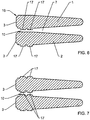
- the filter disk for generating a turbulent flow in the flow gap inlet 10 can also correspond to the Figures 6 and 7 instead of being provided with recesses 11 with one or more beads 17.
- the beads 17 are arranged circumferentially like the recesses 11, the bead height being in the range of 0.5-2 mm
- these beads 17 are arranged on one side on the lower flat side 9 of the filter disc 1, whereas the beads 17 in the embodiment of FIG Figure 7 are formed both on the lower flat side 9 and on the upper flat side 13.
- the formation of the beads 17 depends on the basic fluidic conditions in the flow gap 7.
- cross-sectional design corresponds to that in the Figures 6 and 7 shown filter discs 1 and 2 of those of Figures 4 and 5 ,
Landscapes
- Engineering & Computer Science (AREA)
- Environmental & Geological Engineering (AREA)
- Health & Medical Sciences (AREA)
- Life Sciences & Earth Sciences (AREA)
- Hydrology & Water Resources (AREA)
- Public Health (AREA)
- Water Supply & Treatment (AREA)
- Chemical & Material Sciences (AREA)
- Chemical Kinetics & Catalysis (AREA)
- Filtration Of Liquid (AREA)
Priority Applications (3)
| Application Number | Priority Date | Filing Date | Title |
|---|---|---|---|
| PL16834270T PL3377190T3 (pl) | 2015-11-19 | 2016-11-18 | Tarcza filtracyjna |
| RS20200482A RS60234B1 (sr) | 2015-11-19 | 2016-11-18 | Filterski disk |
| SI201630716T SI3377190T1 (sl) | 2015-11-19 | 2016-11-18 | Filtrirni disk |
Applications Claiming Priority (2)
| Application Number | Priority Date | Filing Date | Title |
|---|---|---|---|
| DE202015106299.0U DE202015106299U1 (de) | 2015-11-19 | 2015-11-19 | Filterscheibe |
| PCT/DE2016/100537 WO2017084657A1 (de) | 2015-11-19 | 2016-11-18 | Filterscheibe |
Publications (2)
| Publication Number | Publication Date |
|---|---|
| EP3377190A1 EP3377190A1 (de) | 2018-09-26 |
| EP3377190B1 true EP3377190B1 (de) | 2020-02-05 |
Family
ID=55644446
Family Applications (1)
| Application Number | Title | Priority Date | Filing Date |
|---|---|---|---|
| EP16834270.7A Active EP3377190B1 (de) | 2015-11-19 | 2016-11-18 | Filterscheibe |
Country Status (9)
| Country | Link |
|---|---|
| EP (1) | EP3377190B1 (pt) |
| DE (2) | DE202015106299U1 (pt) |
| ES (1) | ES2784524T3 (pt) |
| HU (1) | HUE049557T2 (pt) |
| PL (1) | PL3377190T3 (pt) |
| PT (1) | PT3377190T (pt) |
| RS (1) | RS60234B1 (pt) |
| SI (1) | SI3377190T1 (pt) |
| WO (1) | WO2017084657A1 (pt) |
Families Citing this family (4)
| Publication number | Priority date | Publication date | Assignee | Title |
|---|---|---|---|---|
| US10967305B2 (en) | 2017-05-30 | 2021-04-06 | Specialized Desanders Inc. | Boundary layer modification in closely-spaced passages |
| CA3006558C (en) | 2017-05-30 | 2022-04-12 | Specialized Desanders Inc. | Gravity desanding apparatus with filter polisher |
| AU2018295591B2 (en) * | 2017-07-06 | 2023-08-03 | Specialized Desanders Inc. | Boundary layer modification in a stacked-plate apparatus |
| US12023629B2 (en) | 2020-08-21 | 2024-07-02 | Specialized Desanders Inc. | Stacked-plate filters, filter plates, and methods for a stacked-plate filter |
Family Cites Families (5)
| Publication number | Priority date | Publication date | Assignee | Title |
|---|---|---|---|---|
| CH438220A (de) * | 1965-06-24 | 1967-06-30 | Grundwasserbauten Ag F | Anschwemm-Filter |
| BE769556A (nl) * | 1971-07-06 | 1971-11-16 | Smet Karel | Filterbuis en ringen gebruikt bij deze filterbuis. |
| DE102006034618B4 (de) | 2006-07-27 | 2011-01-27 | Hobas Engineering Gmbh | Filterrohr |
| DE202007012613U1 (de) * | 2007-09-08 | 2009-01-08 | Stüwa Konrad Stükerjürgen GmbH | Brunnenfilter |
| ES2346842B2 (es) * | 2009-06-26 | 2011-07-01 | Universidad Politécnica de Madrid | Paquete filtrante secuencial para fluidos. |
-
2015
- 2015-11-19 DE DE202015106299.0U patent/DE202015106299U1/de not_active Expired - Lifetime
-
2016
- 2016-11-18 RS RS20200482A patent/RS60234B1/sr unknown
- 2016-11-18 EP EP16834270.7A patent/EP3377190B1/de active Active
- 2016-11-18 HU HUE16834270A patent/HUE049557T2/hu unknown
- 2016-11-18 PL PL16834270T patent/PL3377190T3/pl unknown
- 2016-11-18 WO PCT/DE2016/100537 patent/WO2017084657A1/de not_active Ceased
- 2016-11-18 SI SI201630716T patent/SI3377190T1/sl unknown
- 2016-11-18 PT PT168342707T patent/PT3377190T/pt unknown
- 2016-11-18 DE DE112016005315.0T patent/DE112016005315A5/de not_active Withdrawn
- 2016-11-18 ES ES16834270T patent/ES2784524T3/es active Active
Also Published As
| Publication number | Publication date |
|---|---|
| ES2784524T3 (es) | 2020-09-28 |
| EP3377190A1 (de) | 2018-09-26 |
| RS60234B1 (sr) | 2020-06-30 |
| WO2017084657A1 (de) | 2017-05-26 |
| DE202015106299U1 (de) | 2016-03-07 |
| DE112016005315A5 (de) | 2018-11-15 |
| PL3377190T3 (pl) | 2020-09-21 |
| HUE049557T2 (hu) | 2020-10-28 |
| SI3377190T1 (sl) | 2020-07-31 |
| PT3377190T (pt) | 2020-04-24 |
Similar Documents
| Publication | Publication Date | Title |
|---|---|---|
| EP1062047B1 (de) | Zyklonabscheider | |
| EP3377190B1 (de) | Filterscheibe | |
| DE112017001107T5 (de) | Filterelement | |
| EP2952091A1 (de) | Tropfbewässerungsrohr mit darin eingesetzten Dosierelementen | |
| DE202017001238U1 (de) | Kunststoff-Magnetseparationsplatte zur Durchführung automatischer Magnetseparationsprozesse | |
| EP3523010B1 (de) | Filterelement, insbesondere zur gasfiltration | |
| DE102015008873B4 (de) | Filtereinrichtung mit einem hohlzylindrischen Filtermediumkörperund Abstützdom für eine Filtereinrichtung | |
| EP2910290B1 (de) | Flüssigkeitsfilter | |
| DE202016000637U1 (de) | Urinalsieb | |
| DE102014114592A1 (de) | Filterpatrone zur Reinigung von Luft | |
| EP0366903B1 (de) | Filterdüse mit ringförmigen Filterlamellen | |
| EP3268654B1 (de) | Dämpfungsvorrichtung | |
| DE102009038743A1 (de) | Schälscheibe einer Zentrifuge | |
| DE202012002449U1 (de) | Kerzenförmiger Filter, umfassend mehrere übereinander angeordnete Lamellen | |
| DE2157444A1 (de) | Verfahren zur Abtrennung von in Flüssigkeiten suspendierten Teilchen und dynamische Trenneinrichtung zur Durchführung des Verfahrens | |
| EP3199715B1 (de) | Überlauf für ein becken, insbesondere spülenbecken | |
| WO2014108260A1 (de) | Filtereinrichtung | |
| DE102009004801A1 (de) | Vorrichtung zum Filtern von Fluid-Feststoff-Gemischen | |
| WO2007065630A1 (de) | Rückschlagventil | |
| EP1419807B1 (de) | Filtereinrichtung mit einem auswechselbaren Filterelement | |
| DE102014009181A1 (de) | Rückspülbares Filterelement und Einrichtung zum Reinigen von Bearbeitungsmedium | |
| EP1499416A1 (de) | Filtervorrichtung mit integrierter zentrifugalabscheidung | |
| DE202013102854U1 (de) | Absturz, und Schachtanordnung | |
| DE102017128560B3 (de) | Vorrichtung zum Abscheiden von Sinkstoffen aus Flüssigkeiten, Reinigungseinrichtung und Verfahren zum Abscheiden von Sinkstoffen | |
| AT507726B1 (de) | Hydroventil |
Legal Events
| Date | Code | Title | Description |
|---|---|---|---|
| STAA | Information on the status of an ep patent application or granted ep patent |
Free format text: STATUS: UNKNOWN |
|
| STAA | Information on the status of an ep patent application or granted ep patent |
Free format text: STATUS: THE INTERNATIONAL PUBLICATION HAS BEEN MADE |
|
| PUAI | Public reference made under article 153(3) epc to a published international application that has entered the european phase |
Free format text: ORIGINAL CODE: 0009012 |
|
| STAA | Information on the status of an ep patent application or granted ep patent |
Free format text: STATUS: REQUEST FOR EXAMINATION WAS MADE |
|
| 17P | Request for examination filed |
Effective date: 20180521 |
|
| AK | Designated contracting states |
Kind code of ref document: A1 Designated state(s): AL AT BE BG CH CY CZ DE DK EE ES FI FR GB GR HR HU IE IS IT LI LT LU LV MC MK MT NL NO PL PT RO RS SE SI SK SM TR |
|
| AX | Request for extension of the european patent |
Extension state: BA ME |
|
| DAV | Request for validation of the european patent (deleted) | ||
| DAX | Request for extension of the european patent (deleted) | ||
| GRAP | Despatch of communication of intention to grant a patent |
Free format text: ORIGINAL CODE: EPIDOSNIGR1 |
|
| STAA | Information on the status of an ep patent application or granted ep patent |
Free format text: STATUS: GRANT OF PATENT IS INTENDED |
|
| INTG | Intention to grant announced |
Effective date: 20191021 |
|
| GRAS | Grant fee paid |
Free format text: ORIGINAL CODE: EPIDOSNIGR3 |
|
| GRAA | (expected) grant |
Free format text: ORIGINAL CODE: 0009210 |
|
| STAA | Information on the status of an ep patent application or granted ep patent |
Free format text: STATUS: THE PATENT HAS BEEN GRANTED |
|
| AK | Designated contracting states |
Kind code of ref document: B1 Designated state(s): AL AT BE BG CH CY CZ DE DK EE ES FI FR GB GR HR HU IE IS IT LI LT LU LV MC MK MT NL NO PL PT RO RS SE SI SK SM TR |
|
| REG | Reference to a national code |
Ref country code: GB Ref legal event code: FG4D Free format text: NOT ENGLISH |
|
| REG | Reference to a national code |
Ref country code: AT Ref legal event code: REF Ref document number: 1229511 Country of ref document: AT Kind code of ref document: T Effective date: 20200215 |
|
| REG | Reference to a national code |
Ref country code: DE Ref legal event code: R096 Ref document number: 502016008671 Country of ref document: DE |
|
| REG | Reference to a national code |
Ref country code: IE Ref legal event code: FG4D Free format text: LANGUAGE OF EP DOCUMENT: GERMAN |
|
| REG | Reference to a national code |
Ref country code: CH Ref legal event code: EP |
|
| REG | Reference to a national code |
Ref country code: PT Ref legal event code: SC4A Ref document number: 3377190 Country of ref document: PT Date of ref document: 20200424 Kind code of ref document: T Free format text: AVAILABILITY OF NATIONAL TRANSLATION Effective date: 20200417 |
|
| REG | Reference to a national code |
Ref country code: RO Ref legal event code: EPE |
|
| REG | Reference to a national code |
Ref country code: NL Ref legal event code: FP |
|
| REG | Reference to a national code |
Ref country code: CH Ref legal event code: NV Representative=s name: KATZAROV SA, CH |
|
| REG | Reference to a national code |
Ref country code: SE Ref legal event code: TRGR |
|
| PG25 | Lapsed in a contracting state [announced via postgrant information from national office to epo] |
Ref country code: FI Free format text: LAPSE BECAUSE OF FAILURE TO SUBMIT A TRANSLATION OF THE DESCRIPTION OR TO PAY THE FEE WITHIN THE PRESCRIBED TIME-LIMIT Effective date: 20200205 Ref country code: NO Free format text: LAPSE BECAUSE OF FAILURE TO SUBMIT A TRANSLATION OF THE DESCRIPTION OR TO PAY THE FEE WITHIN THE PRESCRIBED TIME-LIMIT Effective date: 20200505 |
|
| REG | Reference to a national code |
Ref country code: LT Ref legal event code: MG4D |
|
| PG25 | Lapsed in a contracting state [announced via postgrant information from national office to epo] |
Ref country code: HR Free format text: LAPSE BECAUSE OF FAILURE TO SUBMIT A TRANSLATION OF THE DESCRIPTION OR TO PAY THE FEE WITHIN THE PRESCRIBED TIME-LIMIT Effective date: 20200205 Ref country code: GR Free format text: LAPSE BECAUSE OF FAILURE TO SUBMIT A TRANSLATION OF THE DESCRIPTION OR TO PAY THE FEE WITHIN THE PRESCRIBED TIME-LIMIT Effective date: 20200506 Ref country code: LV Free format text: LAPSE BECAUSE OF FAILURE TO SUBMIT A TRANSLATION OF THE DESCRIPTION OR TO PAY THE FEE WITHIN THE PRESCRIBED TIME-LIMIT Effective date: 20200205 Ref country code: IS Free format text: LAPSE BECAUSE OF FAILURE TO SUBMIT A TRANSLATION OF THE DESCRIPTION OR TO PAY THE FEE WITHIN THE PRESCRIBED TIME-LIMIT Effective date: 20200605 Ref country code: BG Free format text: LAPSE BECAUSE OF FAILURE TO SUBMIT A TRANSLATION OF THE DESCRIPTION OR TO PAY THE FEE WITHIN THE PRESCRIBED TIME-LIMIT Effective date: 20200505 |
|
| REG | Reference to a national code |
Ref country code: ES Ref legal event code: FG2A Ref document number: 2784524 Country of ref document: ES Kind code of ref document: T3 Effective date: 20200928 |
|
| REG | Reference to a national code |
Ref country code: HU Ref legal event code: AG4A Ref document number: E049557 Country of ref document: HU |
|
| PG25 | Lapsed in a contracting state [announced via postgrant information from national office to epo] |
Ref country code: CZ Free format text: LAPSE BECAUSE OF FAILURE TO SUBMIT A TRANSLATION OF THE DESCRIPTION OR TO PAY THE FEE WITHIN THE PRESCRIBED TIME-LIMIT Effective date: 20200205 Ref country code: SK Free format text: LAPSE BECAUSE OF FAILURE TO SUBMIT A TRANSLATION OF THE DESCRIPTION OR TO PAY THE FEE WITHIN THE PRESCRIBED TIME-LIMIT Effective date: 20200205 Ref country code: LT Free format text: LAPSE BECAUSE OF FAILURE TO SUBMIT A TRANSLATION OF THE DESCRIPTION OR TO PAY THE FEE WITHIN THE PRESCRIBED TIME-LIMIT Effective date: 20200205 Ref country code: SM Free format text: LAPSE BECAUSE OF FAILURE TO SUBMIT A TRANSLATION OF THE DESCRIPTION OR TO PAY THE FEE WITHIN THE PRESCRIBED TIME-LIMIT Effective date: 20200205 Ref country code: EE Free format text: LAPSE BECAUSE OF FAILURE TO SUBMIT A TRANSLATION OF THE DESCRIPTION OR TO PAY THE FEE WITHIN THE PRESCRIBED TIME-LIMIT Effective date: 20200205 Ref country code: DK Free format text: LAPSE BECAUSE OF FAILURE TO SUBMIT A TRANSLATION OF THE DESCRIPTION OR TO PAY THE FEE WITHIN THE PRESCRIBED TIME-LIMIT Effective date: 20200205 |
|
| REG | Reference to a national code |
Ref country code: DE Ref legal event code: R097 Ref document number: 502016008671 Country of ref document: DE |
|
| PLBE | No opposition filed within time limit |
Free format text: ORIGINAL CODE: 0009261 |
|
| STAA | Information on the status of an ep patent application or granted ep patent |
Free format text: STATUS: NO OPPOSITION FILED WITHIN TIME LIMIT |
|
| 26N | No opposition filed |
Effective date: 20201106 |
|
| PG25 | Lapsed in a contracting state [announced via postgrant information from national office to epo] |
Ref country code: MC Free format text: LAPSE BECAUSE OF FAILURE TO SUBMIT A TRANSLATION OF THE DESCRIPTION OR TO PAY THE FEE WITHIN THE PRESCRIBED TIME-LIMIT Effective date: 20200205 |
|
| PG25 | Lapsed in a contracting state [announced via postgrant information from national office to epo] |
Ref country code: LU Free format text: LAPSE BECAUSE OF NON-PAYMENT OF DUE FEES Effective date: 20201118 |
|
| REG | Reference to a national code |
Ref country code: BE Ref legal event code: MM Effective date: 20201130 |
|
| PG25 | Lapsed in a contracting state [announced via postgrant information from national office to epo] |
Ref country code: IE Free format text: LAPSE BECAUSE OF NON-PAYMENT OF DUE FEES Effective date: 20201118 |
|
| PG25 | Lapsed in a contracting state [announced via postgrant information from national office to epo] |
Ref country code: MT Free format text: LAPSE BECAUSE OF FAILURE TO SUBMIT A TRANSLATION OF THE DESCRIPTION OR TO PAY THE FEE WITHIN THE PRESCRIBED TIME-LIMIT Effective date: 20200205 Ref country code: CY Free format text: LAPSE BECAUSE OF FAILURE TO SUBMIT A TRANSLATION OF THE DESCRIPTION OR TO PAY THE FEE WITHIN THE PRESCRIBED TIME-LIMIT Effective date: 20200205 |
|
| PG25 | Lapsed in a contracting state [announced via postgrant information from national office to epo] |
Ref country code: MK Free format text: LAPSE BECAUSE OF FAILURE TO SUBMIT A TRANSLATION OF THE DESCRIPTION OR TO PAY THE FEE WITHIN THE PRESCRIBED TIME-LIMIT Effective date: 20200205 Ref country code: AL Free format text: LAPSE BECAUSE OF FAILURE TO SUBMIT A TRANSLATION OF THE DESCRIPTION OR TO PAY THE FEE WITHIN THE PRESCRIBED TIME-LIMIT Effective date: 20200205 |
|
| PG25 | Lapsed in a contracting state [announced via postgrant information from national office to epo] |
Ref country code: BE Free format text: LAPSE BECAUSE OF NON-PAYMENT OF DUE FEES Effective date: 20201130 |
|
| REG | Reference to a national code |
Ref country code: CH Ref legal event code: U11 Free format text: ST27 STATUS EVENT CODE: U-0-0-U10-U11 (AS PROVIDED BY THE NATIONAL OFFICE) Effective date: 20251201 |
|
| PGFP | Annual fee paid to national office [announced via postgrant information from national office to epo] |
Ref country code: PT Payment date: 20251105 Year of fee payment: 10 |
|
| PGFP | Annual fee paid to national office [announced via postgrant information from national office to epo] |
Ref country code: HU Payment date: 20251117 Year of fee payment: 10 |
|
| PGFP | Annual fee paid to national office [announced via postgrant information from national office to epo] |
Ref country code: NL Payment date: 20251119 Year of fee payment: 10 |
|
| PGFP | Annual fee paid to national office [announced via postgrant information from national office to epo] |
Ref country code: DE Payment date: 20250930 Year of fee payment: 10 |
|
| PGFP | Annual fee paid to national office [announced via postgrant information from national office to epo] |
Ref country code: GB Payment date: 20251120 Year of fee payment: 10 |
|
| PGFP | Annual fee paid to national office [announced via postgrant information from national office to epo] |
Ref country code: AT Payment date: 20251117 Year of fee payment: 10 |
|
| PGFP | Annual fee paid to national office [announced via postgrant information from national office to epo] |
Ref country code: IT Payment date: 20251128 Year of fee payment: 10 |
|
| PGFP | Annual fee paid to national office [announced via postgrant information from national office to epo] |
Ref country code: FR Payment date: 20251125 Year of fee payment: 10 |
|
| PGFP | Annual fee paid to national office [announced via postgrant information from national office to epo] |
Ref country code: TR Payment date: 20251113 Year of fee payment: 10 |
|
| PGFP | Annual fee paid to national office [announced via postgrant information from national office to epo] |
Ref country code: CH Payment date: 20251201 Year of fee payment: 10 Ref country code: SE Payment date: 20251119 Year of fee payment: 10 |
|
| PGFP | Annual fee paid to national office [announced via postgrant information from national office to epo] |
Ref country code: PL Payment date: 20251107 Year of fee payment: 10 |
|
| PGFP | Annual fee paid to national office [announced via postgrant information from national office to epo] |
Ref country code: RO Payment date: 20251113 Year of fee payment: 10 |
|
| PGFP | Annual fee paid to national office [announced via postgrant information from national office to epo] |
Ref country code: RS Payment date: 20251106 Year of fee payment: 10 |
|
| PGFP | Annual fee paid to national office [announced via postgrant information from national office to epo] |
Ref country code: SI Payment date: 20251111 Year of fee payment: 10 Ref country code: ES Payment date: 20251216 Year of fee payment: 10 |
|
| REG | Reference to a national code |
Ref country code: DE Ref legal event code: R082 Ref document number: 502016008671 Country of ref document: DE Representative=s name: BRANDT, DETLEF, DIPL.-ING., DE |