EP3377237B1 - Abflussreiniger - Google Patents
Abflussreiniger Download PDFInfo
- Publication number
- EP3377237B1 EP3377237B1 EP17873949.6A EP17873949A EP3377237B1 EP 3377237 B1 EP3377237 B1 EP 3377237B1 EP 17873949 A EP17873949 A EP 17873949A EP 3377237 B1 EP3377237 B1 EP 3377237B1
- Authority
- EP
- European Patent Office
- Prior art keywords
- drum
- coupled
- base unit
- drain cleaner
- housing
- Prior art date
- Legal status (The legal status is an assumption and is not a legal conclusion. Google has not performed a legal analysis and makes no representation as to the accuracy of the status listed.)
- Active
Links
Images


Classifications
-
- B—PERFORMING OPERATIONS; TRANSPORTING
- B08—CLEANING
- B08B—CLEANING IN GENERAL; PREVENTION OF FOULING IN GENERAL
- B08B9/00—Cleaning hollow articles by methods or apparatus specially adapted thereto
- B08B9/02—Cleaning pipes or tubes or systems of pipes or tubes
- B08B9/027—Cleaning the internal surfaces; Removal of blockages
- B08B9/04—Cleaning the internal surfaces; Removal of blockages using cleaning devices introduced into and moved along the pipes
- B08B9/043—Cleaning the internal surfaces; Removal of blockages using cleaning devices introduced into and moved along the pipes moved by externally powered mechanical linkage, e.g. pushed or drawn through the pipes
- B08B9/047—Cleaning the internal surfaces; Removal of blockages using cleaning devices introduced into and moved along the pipes moved by externally powered mechanical linkage, e.g. pushed or drawn through the pipes the cleaning devices having internal motors, e.g. turbines for powering cleaning tools
-
- B—PERFORMING OPERATIONS; TRANSPORTING
- B08—CLEANING
- B08B—CLEANING IN GENERAL; PREVENTION OF FOULING IN GENERAL
- B08B9/00—Cleaning hollow articles by methods or apparatus specially adapted thereto
- B08B9/02—Cleaning pipes or tubes or systems of pipes or tubes
- B08B9/027—Cleaning the internal surfaces; Removal of blockages
- B08B9/04—Cleaning the internal surfaces; Removal of blockages using cleaning devices introduced into and moved along the pipes
- B08B9/043—Cleaning the internal surfaces; Removal of blockages using cleaning devices introduced into and moved along the pipes moved by externally powered mechanical linkage, e.g. pushed or drawn through the pipes
- B08B9/045—Cleaning the internal surfaces; Removal of blockages using cleaning devices introduced into and moved along the pipes moved by externally powered mechanical linkage, e.g. pushed or drawn through the pipes the cleaning devices being rotated while moved, e.g. flexible rotating shaft or "snake"
-
- E—FIXED CONSTRUCTIONS
- E03—WATER SUPPLY; SEWERAGE
- E03F—SEWERS; CESSPOOLS
- E03F9/00—Arrangements or fixed installations methods or devices for cleaning or clearing sewer pipes, e.g. by flushing
- E03F9/002—Cleaning sewer pipes by mechanical means
- E03F9/005—Apparatus for simultaneously pushing and rotating a cleaning device carried by the leading end of a cable or an assembly of rods
-
- B—PERFORMING OPERATIONS; TRANSPORTING
- B65—CONVEYING; PACKING; STORING; HANDLING THIN OR FILAMENTARY MATERIAL
- B65H—HANDLING THIN OR FILAMENTARY MATERIAL, e.g. SHEETS, WEBS, CABLES
- B65H2701/00—Handled material; Storage means
- B65H2701/30—Handled filamentary material
- B65H2701/39—Other types of filamentary materials or special applications
- B65H2701/3917—Faired cables
Definitions
- the present invention relates to drain cleaners (see for example EP 0065474 A1 ).
- Drain cleaners are used to clear clogs and other debris out of drains and other types of conduits.
- a drain cleaner typically includes an elongated cable that can be inserted into a drain. The cable may be rotated, or spun, to help break up clogs within the drain. More recent drain cleaners include motors to help spin the cables. These drain cleaners, however, may be relatively heavy and/or bulky, making them difficult to transport.
- the invention provides a drain cleaner as defined in claim 1. Further advantageous features are defined in the dependent claims.
- FIGS. 1-5 illustrate a drain cleaner 100 including a first unit 104 and a second unit 108.
- the first unit 104 is a base unit or drive unit.
- the second unit 108 is a drum unit.
- the drain cleaner 100 is modular such that the second unit 108 is removable from the first unit 104.
- the first unit 104 includes a motor, a battery pack 164, and a stand portion or stabilizer. Although not shown in these figures, the first unit 104 can also include backpack-style straps.
- the second unit 108 is removable from the first unit 104 and includes a contained cable drum.
- the drum can be dropped into place to interface with the motor and be rotated by the motor, e.g., moved solely in the vertical direction relative to the first unit 104 to interface the second unit 108 with the first unit 104 such that the drum can be rotated by the first unit 104.
- the drum can also be carried separately from the motor, the battery 164, and the stand portion to provide easier, more manageable carrying of the heavy drain cleaner 100 by a user.
- the user can distribute the weight of the drain cleaner 100 between the drum carried in the user's hands and the first unit 104 carried on the user's back using the backpack straps.
- various different drums, e.g., containing different sizes, lengths, types, etc. of cables can be attached to the same first unit.
- the first unit 104 can be used to drive various different drums containing various different cables.
- drain cleaner includes a retention mechanism (e.g., a hook, a magnet, etc.) either on an exterior of the drum or on the driving unit.
- the retention mechanism is configured to retain (e.g., temporarily hold) the end of the old cable while the user changes the drum and the user is ready to connect the end of the old cable to the end of the new cable.
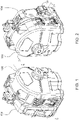
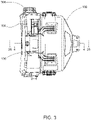
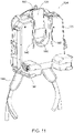
- FIG. 11 illustrates the drive unit 104 of a drain cleaner 100.
- the drive unit 104 includes a vertical slot 136 configured to receive a portion of a drum that is driven by the drive unit 104 to spin a cable.
- the drive unit 104 includes a belt and pulley system.
- a driven shaft of the drum is driven by an exterior surface of the belt. This arrangement allows for easy attachment and removal of the drum from the drive unit 104 (e.g., through a simple vertical sliding motion), without disassembling the drive unit 104, removing the belt, etc.
- the relatively low locations of the drive wheel and the motor allows for the weight of the motor to be distributed below an axis of rotation of the drum, providing a stable base for the drive unit 104 and the drum.
- the drive unit 104 of the drain cleaner 100 may be controlled by a foot pedal 165.
- the illustrated drive unit 104 may be activated by an electronic foot pedal 165 that is electrically coupled to a controller of the motor 170.
- the electronic foot pedal 165 allows for superior control and guaranteed actuation compared to conventional foot pedals with air switches.
- the electronic foot pedal 165 allows for variable speeds, is fully sealed for water resistance, and includes a quick-connect cord for serviceability and storage advantages.
- the foot pedal 165 may allow the drain cleaner 100 to operate at multiple speeds between zero speed (i.e., off or stopped) and full speed. In other embodiments, the foot pedal 165 may not be variable speed, but may simply turn the drain cleaner 100 on and off.
- the motor of the drain cleaner 100 may also include an electronic brake to slow rotation of the drum when a user releases (e.g., takes his/her foot off of) the foot pedal 165.
- Electronic components (not shown) associated with the motor may also provide a breaking force to slow the rotation of the drum.
- the electronic brake is a soft-style brake that gradually stops rotation of the drum, rather than suddenly stopping rotation of the drum when the foot pedal 165 is released.
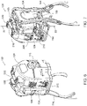
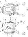
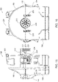
- FIGS. 6-9 illustrate the drain cleaner 100 in more detail.
- the drain cleaner 100 is configured to rest on the ground and remain upright during operation.
- the illustrated drain cleaner 100 includes a base unit 104, an outer casing or an outer drum 108, and an inner drum 112 ( FIGS. 17-18 ).
- the base unit 104 supports the outer drum 108 and the inner drum 112 on the ground.
- the inner drum 112 is supported within the outer drum 108, and the outer drum 108 is removable with the inner drum 112 from the base unit 104.
- the inner drum 112 houses a flexible cable, or spring, which can be fed out of the drain cleaner 100 through an opening 116 in the outer drum 108 and into a drain.
- the base unit 104 is coupled to the inner drum 112 to rotate the inner drum 112 and, thereby, the flexible cable.
- the illustrated base unit 104 includes a housing 120, a drive arrangement 124 positioned within the housing 120, and a battery receptacle 128 supported by the housing 120.
- the housing 120 includes a lower surface 132 that defines a base of the drain cleaner 100.
- the illustrated housing 120 further includes a relatively large vertical slot 136 and two smaller guide slots 140.
- the large vertical slot 136 receives a portion of the inner drum 112 to operatively couple the inner drum 112 to the base unit 104, as described below.
- the guide slots 140 receive portions of the outer drum 108 to help align the outer and inner drums 108, 112 on the base unit 104.
- the base unit 104 also includes a strap arrangement 144 coupled to the housing 120 so that the drain cleaner 100 can be carried like a backpack.
- the strap arrangement 144 may include snaps 146, or other coupling mechanisms, coupled near a top and a bottom of each strap.
- the snaps 146 may couple together to lift lower portions of each strap away from the ground (as shown in FIG. 11B ) and, thereby, out of any mess that may be on the floor of a jobsite.
- the strap arrangement 144 may be omitted.
- the illustrated drive arrangement 124 is a belt drive arrangement including a drive pulley 148, two idler pulleys 152, and a belt 156.
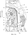
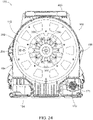
- the drive pulley 148 is coupled to an output shaft 160 of a motor 170 ( FIG. 24 ).
- the idler pulleys 152 are supported by a mounting plate or backbone 169 of the housing 120 and are spaced apart from the drive pulley 156.
- each idler pulley 152 is positioned on one side of the vertical slot 136 ( FIG. 11 ).
- the belt 156 wraps around the pulleys 148, 152 and is driven by the drive pulley 148.
- a section of the belt 156 is exposed at and extends across the vertical slot 136. This section of the belt 156 is engaged by a portion of the inner drum 112 to rotate the inner drum 112.
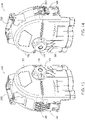
- the drive arrangement 124 also includes a tensioner 161 mounted to one of the idler pulleys 152.
- the illustrated tensioner 161 includes an elongated opening 162 that receives and rides along a boss 163 in the base unit 104. The boss 163 extends from the backbone 169 of the housing 120.
- the tensioner 161 is configured to allow the idler pulley 152 to move vertically relative to the housing 120.
- the tensioner 161 is biased in the direction of arrow A (upward in FIG. 12A ) by two springs 165 (e.g., coil springs). In other embodiments, the tensioner 161 may be biased by fewer or more springs.
- the tensioner 161 allows the idler pulley 152 to move in the direction of arrow B (downward in FIG. 12A ) to help properly tension the belt 156.
- the battery receptacle 128 is formed in the housing 120.
- the battery receptacle 128 is configured to receive a battery pack 164, such as an 18V Li-ion power tool battery pack.
- the battery receptacle 128 electrically couples the battery pack 164 to the motor 170 ( FIG. 24 ) to selectively power the motor 170.
- the motor 170 rotates the output shaft 160 to rotate the drive pulley 148 and, thereby, move the belt 156 about the drive arrangement 124.
- the motor 170 also includes a speed reducing gearbox with a plurality of gears 171.
- the illustrated drain cleaner 100 is controlled by a foot pedal 165 ( FIGS. 10 and 11 ).
- the foot pedal 165 is coupled to the battery pack 164 and the motor 170 ( FIG. 24 ) to control the motor 170 (e.g., start and stop the motor 170).
- the foot pedal 165 allows a user to remotely control the motor 170 by actuating (e.g., depressing) the foot pedal 165.
- the foot pedal 165 can be stored at least partially within the vertical slot 136 of the base unit 104.
- the illustrated foot pedal 165 includes two inverted bosses 166, or cavities, that match two bosses 167 on the top of the base unit 104 adjacent the vertical slot 136.
- the inverted bosses 166 on the foot pedal 165 receive the bosses 167 of the base unit 104 to help properly align and store the foot pedal 165 in the vertical slot 136.
- the positions of the inverted bosses 166 and the bosses 167 may be reversed, and/or the foot pedal 165 may include other coupling means for removably connecting the foot pedal 165 to the base unit 104.
- the illustrated base unit 104 also includes a stabilizer 168.
- the stabilizer 168 includes a rod member 172 and two feet 176 that are coupled to the rod member 172.
- the rod member 172 is bent into a general U-shape.
- the feet 176 are coupled to corners of the U-shape.
- a handle 180 is coupled to the rod member 172 between the feet 176. The handle 180 helps a user grasp the stabilizer 168 to move the stabilizer 168 relative to the base unit 104.
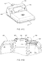
- the stabilizer 168 is linearly slidable into and out of the base unit 104 between a retracted position ( FIG. 7 ) and an extended position ( FIG. 10 ).
- the base unit 104 While in the retracted position, the base unit 104 is relatively compact. While in the extended position, the base unit 104 has a larger base for stability.
- the stabilizer 168 creates a tripod-like support between the feet 176 and the outer drum 108.
- the illustrated stabilizer 168 is movable to a range of positions between the retracted position and a fully extended position to fit within different sized work areas.
- the base unit 104 includes a detent mechanism to retain the stabilizer 168 in the retracted position ( FIG. 10A ) and the fully extended position ( FIG. 10B ).
- the detent mechanism includes two sets of spring members 182A, 182B supported by the base unit 104 and projections 183 coupled to the rod member 172.
- the illustrated projections 183 are integrally formed with the rod member 172 adjacent ends of the rod member 172.
- the projections 183 engage the first set of spring members 182A to inhibit the rod member 172 from freely sliding out of the base unit 104.
- the projections 183 engage the second set of spring members 182B to inhibit the rod member 172 from freely sliding into the base unit 104.
- the detent mechanism may include additional sets of spring members to retain the stabilizer 168 in other positions.
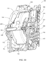
- the outer drum 108 includes a clamshell housing 184 that receives the inner drum 112.
- the illustrated clamshell housing 184 includes a lower housing portion 188, an upper housing portion 192, a hinge 196, and a latch 200.
- the upper housing portion 192 is pivotally coupled to the lower housing portion 188 by the hinge 196.
- the upper housing portion 192 is movable (e.g., pivotable) about the hinge 196 relative to the lower housing portion 188 between a closed position and an open position.
- the clamshell housing 184 substantially encloses and protects the inner drum 112.
- the inner drum 112 is exposed and may be removable from the outer drum 108.
- the latch 200 extends between the lower and upper housing portions 188, 192 and selectively secures the upper housing portion 192 in the closed position.
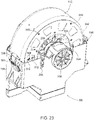
- the outer drum 108 is selectively coupled to the base unit 104 by inserting (e.g., dropping) the outer drum 108 onto the base unit 104 from vertically above the base unit 104.
- the outer drum 108 includes two guide rails 204 extending from a rear of the clamshell housing 184.
- the guide rails 204 are configured to fit within the guide slots 140 ( FIG. 11 ) of the base unit 104 to help align the outer drum 108 on the base unit 104.
- a driven pulley 208 of the inner drum 112 also extends outwardly from the rear of the clamshell housing 184.
- the driven pulley 208 is configured to fit within the vertical slot 136 ( FIG.
- a shield 212 of the outer drum 108 extends over the driven pulley 208 to help cover and protect the driven pulley 208 when the driven pulley 208 is received in the vertical slot 136.
- two latches 216 selectively secure the outer drum 108 to the base unit 104.
- the latches 216 are positioned on opposing sides of the outer drum 108 and engage corresponding features on the base unit 104.
- the latches 216 are over-center latches.
- other coupling mechanisms may be used to secure the outer drum 108 to the base unit 104.
- the weight of the outer drum 108 and the securement of the latches 216 create sufficient force between the driven pulley 208 and the belt 156 ( FIG. 11 ) to tension the belt 156 when the outer drum 108 is connected to the base unit 104.
- the outer drum 108 also includes a handle 220.
- the illustrated handle 220 is pivotally coupled to the upper housing portion 192.
- the handle 220 facilitates lifting the outer drum 108 apart from the base unit 104.
- the handle 220 also facilitates carrying the outer drum 108 (with the inner drum 112) apart from the base unit 104.
- the handle 220 further facilitates inserting the outer drum 108 onto the base unit 104.
- the handle 220 can also be used to lift and carry the entire drain cleaner 100.
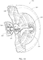
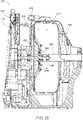
- the inner drum 112 includes a generally cylindrical housing 224, a guide conduit 228, a driven shaft 232, and the driven pulley 208.
- the housing 224 is configured to receive and store the flexible cable of the drain cleaner 100.
- the housing 224 includes weep holes 236 formed in the perimeter of the housing 224. The weeps holes 236 provide drains into the outer drum 108, keeping the flexible cable from sitting in water if the inner drum 112 is not emptied.
- the guide conduit 228 guides the flexible cable from the housing 224 to the opening 116 ( FIG. 6 ) in the outer drum 108.
- the driven shaft 232 is coupled to the guide conduit 228.
- the driven shaft 232 extends through a first bearing 238 and a second bearing 239, and into the guide conduit 228.
- the first bearing 238 and the second bearing 239 allow the driven shaft 232 and the guide conduit 228 to support each other.
- the first bearing 238 and the second bearing 239 also allow the guide conduit 228 to spin independently of the housing 224 and the driven shaft 232 in order to allow the flexible cable to properly feed into or out of the housing 224.
- the driven shaft 232 is coupled to and extends rearwardly from the housing 224.
- the driven pulley 208 is coupled to a distal end of the driven shaft 232. More particularly, the driven pulley 208 is fixed to the driven shaft 232.
- the driven pulley 208 rotates the driven shaft 232, which rotates the housing 224 and spins the flexible cable.
- the inner drum 112 also includes two bearings 240, 244 that support the inner drum 112 within the outer drum 108 for rotation relative to the outer drum 108.
- the first bearing 240 is located on the guide conduit 228.
- the second bearing 244 is located on the driven shaft 232.
- the bearings 240, 244 are located between sections of the lower housing portion 188 and the upper housing portion 192 of the clamshell housing 184 when the outer drum 108 is closed.
- each bearing 240, 244 is secured to the lower housing portion 188 by a bearing clamp that keeps the inner drum 112 connected to the lower housing portion 188 when the outer drum 108 is opened.
- the inner drum 112 can be removed from the outer drum 108 (by also removing the bearing clamps), facilitating cleaning of the inner drum 112 and the outer drum 108.
- the inner drum 112 also includes a securement member 246 coupled to an inner surface of the drum 112.
- the securement member 246 is a metal stamping formed as a U-shaped bracket.
- the illustrated securement member 246 is secured to the drum 112 by threaded fasteners.
- the securement member 246 provides a connection point for securing the flexible cable to the inner drum 112. More particularly, the securement member 246 engages a leader cable having a connector at its distal end.
- the connector is configured to attach to a proximal end of another flexible cable that is inserted into the drain, allowing a user to detach an "effective" cable from the drum 112 without opening the drum 112 or sticking one's hands inside the drum 112.
- the leader cable may be about three feet in length. In other embodiments, the leader cable may be longer or shorter.
- the outer drum 108 and the inner drum 112 are connected to the base unit 104.
- the driven pulley 208 of the inner drum 112 is received in the vertical slot 136 of the base unit 104 so the inner drum 112 engages the belt 156 of the drive arrangement 124.
- the weight of the drum unit on the belt 156 tensions the belt 156 so movement (e.g., rotation) of the belt 156 also drives the driven pulley 208 and, thereby, the inner drum 112.
- the belt 156 is rotated by selectively energizing the motor 170 ( FIG. 24 ) with the battery pack 164 to drive the drive arrangement 124.
- the flexible cable stored within the inner drum 112 is also rotated or spun.
- a user can feed the flexible cable into or out of the drum unit by manually pushing/pulling the flexible cable or by using a suitable feed mechanism coupled to the cable.
- FIG. 21 illustrates a variety of attachments that can be coupled to an end of the flexible cable.
- the attachments are tools that can be inserted into a drain with the flexible cable to help clean the drain.
- the illustrated attachments include a large drop head 248, a smaller drop head 252, a bulb head 256, a C-shaped cutter 260, and a spade-shaped cutter 264.
- Other types of attachments may also or alternatively be connected to the flexible cable.
- the foot pedal 165 includes a first cavity 268 and a second or sealed cavity 272.
- a separator or sealing member 276 is positioned between the first cavity 268 and the sealed cavity 272.
- the sealing member 276 is made from a flexible material (e.g., rubber) and limits liquids from entering the sealed compartment 272 from the first compartment 268 or an external environment.
- An actuation lever 280 is positioned within the first cavity 268 and is aligned with a switch 284 positioned within the sealed cavity 272. In the illustrated embodiment, the switch 284 is positioned adjacent to the sealing sheet 276, while the actuation lever 280 is spaced apart from the sealing sheet 276.
- the user may actuate a button on a feed switch 316 positioned on the base unit 104 proximate the vertical slot 136 ( FIG. 11D ).
- the feed switch 316 includes three distinct buttons.
- a first or feed button 320 ( FIG. 11D ) may be selected to operate the motor 170 ( FIG. 24 ) in a clockwise direction and feed the cable out of the outer drum 108.
- a second or retract button 324 ( FIG. 11D ) may be selected to operate the motor 170 in a counter clockwise direction and retract the extended cable back within the outer drum 108.
- a third or neutral button 328 ( FIG. 11D ) may be selected so that the motor 170 is not operated.
- buttons 320, 324, 328 of the feed switch 316 is monitored with a microcontroller (not shown) and electrically connected in series with an electrical signal from the foot pedal 165. Signal level current, not motor current, passes through the contacts of the feed switch 316.
- the signal from the foot pedal 165 is decoupled from a microcontroller input.
- actuating the foot pedal 165 while the neutral button 328 is pressed will not operate the motor 170.
- the feed button 320 or the retract button 324 are toggled to from the neutral button 328 while the foot pedal 165 is actuated, the motor 170 will not operate.
- the user must release the foot pedal 165 before selecting a different button 320, 324 in order for the actuation of the foot pedal 165 to result the microcontroller receiving a new input signal.
- the microcontroller will stop operating the motor 170. Similar to toggling off of the neutral button 328, the user must release the foot pedal 165 and reselect the desired button (i.e., the feed button 320 or the retract button 324) before reactuating the foot pedal 165.
- the inner drum 112 includes an outer reinforcement plate 292 and inner reinforcement plates 296, although in other embodiments, the inner drum 112 may include only one reinforcement plate 292, 296 or no reinforcement plates.
- the reinforcement plates 292, 296 are made from metal, while the inner drum 112 is made from a less hard material, such as plastic.
- the outer reinforcement plate 292 is coupled to an outer surface of the inner drum 112 proximate the driven pulley 208 via fastening members 300 (e.g., self-tapping screws).
- the inner reinforcement plates 296 are coupled to either side of an inner surface of the inner drum 112 proximate the driven shaft 232 ( FIG.
- the reinforcement plates 292, 296 provide additional strength to the inner drum 112 in order to limit deflection to the inner drum 112 caused by cables during operation.
- the inner drum 112 is made from plastic and over time, the friction between the cables and a surface of the inner drum 112 may wear through the inner drum 112.
- the reinforcement plates 292, 296 guard against wear caused by the cables in order to protect the surface of the inner drum 112.
- the inner drum 112 includes an alternate embodiment of a securement clamp 308.
- the securement clamp 308 is a U-bolt.
- the cable clamp 308 extends through the inner surface of the inner drum 112 so that a curved portion of the U-bolt 308 is proximate the first bearing 240.
- Cap nuts 312 couple to the U-bolt 308 proximate the outer reinforcement plate 292.
- the U-bolt 308 engages a leader cable having a connector at its distal end.
- the connector is configured to attach to a proximal end of another flexible cable that is inserted into the drain, allowing a user to detach an "effective" cable from the drum 112 without opening the drum 112 or sticking one's hands inside the drum 112.
Landscapes
- Engineering & Computer Science (AREA)
- Mechanical Engineering (AREA)
- Health & Medical Sciences (AREA)
- Life Sciences & Earth Sciences (AREA)
- Hydrology & Water Resources (AREA)
- Public Health (AREA)
- Water Supply & Treatment (AREA)
- Devices For Medical Bathing And Washing (AREA)
- Toys (AREA)
- Harvester Elements (AREA)
- Devices For Conveying Motion By Means Of Endless Flexible Members (AREA)
- Accessory Of Washing/Drying Machine, Commercial Washing/Drying Machine, Other Washing/Drying Machine (AREA)
Claims (15)
- Abflussreiniger (100), umfassend:eine Basiseinheit (104), die ein Gehäuse (120), eine Antriebsanordnung (124), die innerhalb des Gehäuses positioniert ist, und einen Motor (170), der mit der Antriebsanordnung gekoppelt ist und von dem Gehäuse getragen wird, einschließt, wobei der Motor betreibbar ist, um die Antriebsanordnung selektiv anzutreiben; undeine Trommeleinheit, die entfernbar mit der Basiseinheit gekoppelt ist, wobei die Trommeleinheit Folgendes einschließt:ein Außengehäuse (108),eine Innentrommel (112), die in die Antriebsanordnung eingreift, wenn die Trommeleinheit mit der Basiseinheit gekoppelt ist, um die Trommel zu drehen, wobei die Innentrommel innerhalb des Außengehäuses drehbar ist, undein Kabel, das innerhalb der Innentrommel gelagert ist und wahlweise aus dem Außengehäuse und in einen Abfluss ausfahrbar ist,dadurch gekennzeichnet, dass die Trommeleinheit ferner eine Welle (232) und eine mit der Innentrommel gekoppelte Riemenscheibe (208) einschließt, und wobei sich die Welle und die Riemenscheibe aus dem Außengehäuse erstrecken, wobei die Antriebsanordnung ein Antriebsrad (148), das mit einer Ausgangswelle des Motors gekoppelt ist, eine Spannrolle (152), die von einer Montageplatte (169) des Gehäuses getragen wird, und einen Riemen (156), der um das Antriebsrad und die Spannrolle gewickelt ist, einschließt, und wobei die Riemenscheibe (208) der Trommeleinheit mit der Basiseinheit in Eingriff steht, wenn die Trommeleinheit mit der Basiseinheit gekoppelt ist, um die Innentrommel zu drehen.
- Abflussreiniger nach Anspruch 1, wobei die Basiseinheit eine mit dem Gehäuse gekoppelte Gurtanordnung (144) einschließt, wobei die Gurtanordnung konfiguriert ist, um von einem Benutzer getragen zu werden, wobei optional die Trommeleinheit einen Griff (220) einschließt, der mit dem Außengehäuse gekoppelt ist, wobei der Griff konfiguriert ist, um vom Benutzer gehalten zu werden, um die Basiseinheit und die Trommeleinheit separat zu tragen.
- Abflussreiniger nach Anspruch 1, ferner umfassend ein Akkupack (164), das entfernbar mit der Basiseinheit gekoppelt ist, wobei das Akkupack dem Motor Leistung bereitstellt.
- Abflussreiniger nach Anspruch 1, wobei die Basiseinheit ferner einen Stabilisator (168) einschließt, der konfiguriert ist, um die Basiseinheit in einer aufrechten Position zu stützen, und wobei der Stabilisator zwischen einer ersten Position, in der der Stabilisator relativ zu dem Gehäuse eingezogen ist, und einer zweiten Position, in der sich der Stabilisator relativ zu dem Gehäuse nach außen erstreckt, bewegbar ist
- Abflussreiniger nach Anspruch 4, wobei der Stabilisator ein Stangenelement (172) mit einer U-Form und einem mit dem Stangenelement gekoppelten Griff einschließt, wobei in der ersten Position das Stangenelement in dem Gehäuse der Basiseinheit aufgenommen ist, und wobei das Stangenelement in der zweiten Position zumindest teilweise aus dem Gehäuse der Basiseinheit herausgezogen ist.
- Abflussreiniger nach Anspruch 5, wobei die Basiseinheit ferner einen vertikalen Schlitz (136) einschließt, der in dem Gehäuse ausgebildet ist, wobei sich der Riemen über den vertikalen Schlitz erstreckt, und wobei die Riemenscheibe der Trommeleinheit in dem vertikalen Schlitz aufgenommen ist, wenn die Trommeleinheit mit der Basiseinheit gekoppelt ist, um in den Riemen einzugreifen.
- Abflussreiniger nach Anspruch 6, wobei die Antriebsanordnung einen Spanner (161) einschließt, der an der Spannrolle montiert ist, wobei der Spanner einen länglichen Schlitz (162) definiert, der einen Vorsprung (163) aufnimmt, der sich von der Montageplatte des Gehäuses erstreckt, und wobei der Spanner entlang des Vorsprungs bewegbar ist, um eine Position der Spannrolle aufgrund eines Gewichts der Trommeleinheit einzustellen, wenn die Riemenscheibe der Trommeleinheit in den Riemen eingreift.
- Abflussreiniger nach Anspruch 7, wobei die Antriebsanordnung ferner eine Feder (165) einschließt, die mit dem Spanner gekoppelt ist, wobei die Feder den Spanner in einer ersten Richtung vorspannt, und wobei das Gewicht der Trommeleinheit den Spanner in einer zweiten Richtung entgegengesetzt zur ersten Richtung drückt.
- Abflussreiniger nach Anspruch 1, ferner umfassend ein Fußpedal (165), das mit der Basiseinheit gekoppelt ist, und wobei das Fußpedal zum Steuern des Betriebs des Motors betätigbar ist.
- Abflussreiniger nach Anspruch 9, wobei das Fußpedal einen Schalter (284), der innerhalb eines inneren Hohlraums (272) positioniert ist, einen Betätigungshebel (280), der betriebsfähig ist, um den Schalter selektiv in Eingriff zu bringen, und ein Dichtungselement (276), das zwischen dem Betätigungshebel und dem Schalter positioniert ist, einschließt, wobei als Reaktion auf die Betätigung des Fußpedals der Betätigungshebel den Schalter durch das Dichtungselement in Eingriff nimmt.
- Abflussreiniger nach Anspruch 1, wobei die Innentrommel eine aus der Gruppe bestehend aus einer ersten Verstärkungsplatte (292), die mit einer äußeren Oberfläche der Innentrommel gekoppelt ist, einer zweiten Verstärkungsplatte (296), die mit einer inneren Oberfläche der Innentrommel gekoppelt ist, oder sowohl die erste Verstärkungsplatte, die mit der äußeren Oberfläche der Innentrommel gekoppelt ist, als auch die zweite Verstärkungsplatte, die mit der inneren Oberfläche der Innentrommel gekoppelt ist, einschließt.
- Abflussreiniger nach Anspruch 1, wobei die Trommeleinheit eine Führungsleitung (228), die das Kabel aufnimmt, und eine angetriebene Welle (232), die innerhalb der Innentrommel aufgenommen ist, einschließt, wobei die angetriebene Welle mit der Führungsleitung durch ein erstes Lager (238) und ein zweites Lager (239) gekoppelt ist, und wobei das erste Lager und das zweite Lager ermöglichen, dass die angetriebene Welle und die Führungsleitung unabhängig drehen.
- Abflussreiniger nach Anspruch 1, wobei die Basiseinheit ferner einen Schalter (316) mit einer ersten Taste (320), einer zweiten Taste (324) und einer dritten Taste (328) einschließt, wobei das Betätigen der ersten Taste ermöglicht, dass sich der Motor in eine erste Richtung dreht, wobei das Betätigen der zweiten Taste ermöglicht, dass sich der Motor in eine zweite Richtung dreht, und wobei das Betätigen der dritten Taste verhindert, dass der Motor sich dreht.
- Abflussreiniger nach Anspruch 9, wobei die Basiseinheit ferner einen vertikalen Schlitz (136) einschließt, der in dem Gehäuse definiert ist, wobei das Fußpedal abnehmbar in dem vertikalen Schlitz zur Lagerung aufgenommen ist.
- Abflussreiniger nach Anspruch 14, wobei das Gehäuse eine Nabe (167) einschließt, die sich in den vertikalen Schlitz erstreckt, und das Fußpedal einen Hohlraum (166) definiert, und wobei der Hohlraum die Nabe aufnimmt, um das Fußpedal mit der Trommeleinheit zur Lagerung zu koppeln.
Priority Applications (1)
| Application Number | Priority Date | Filing Date | Title |
|---|---|---|---|
| EP22189205.2A EP4123096B1 (de) | 2016-11-28 | 2017-11-28 | Abflussreiniger |
Applications Claiming Priority (3)
| Application Number | Priority Date | Filing Date | Title |
|---|---|---|---|
| US201662426898P | 2016-11-28 | 2016-11-28 | |
| US201762509805P | 2017-05-23 | 2017-05-23 | |
| PCT/US2017/063501 WO2018098487A1 (en) | 2016-11-28 | 2017-11-28 | Drain cleaner |
Related Child Applications (2)
| Application Number | Title | Priority Date | Filing Date |
|---|---|---|---|
| EP22189205.2A Division EP4123096B1 (de) | 2016-11-28 | 2017-11-28 | Abflussreiniger |
| EP22189205.2A Division-Into EP4123096B1 (de) | 2016-11-28 | 2017-11-28 | Abflussreiniger |
Publications (3)
| Publication Number | Publication Date |
|---|---|
| EP3377237A1 EP3377237A1 (de) | 2018-09-26 |
| EP3377237A4 EP3377237A4 (de) | 2019-10-16 |
| EP3377237B1 true EP3377237B1 (de) | 2022-09-14 |
Family
ID=62192651
Family Applications (2)
| Application Number | Title | Priority Date | Filing Date |
|---|---|---|---|
| EP22189205.2A Active EP4123096B1 (de) | 2016-11-28 | 2017-11-28 | Abflussreiniger |
| EP17873949.6A Active EP3377237B1 (de) | 2016-11-28 | 2017-11-28 | Abflussreiniger |
Family Applications Before (1)
| Application Number | Title | Priority Date | Filing Date |
|---|---|---|---|
| EP22189205.2A Active EP4123096B1 (de) | 2016-11-28 | 2017-11-28 | Abflussreiniger |
Country Status (4)
| Country | Link |
|---|---|
| US (3) | US10722928B2 (de) |
| EP (2) | EP4123096B1 (de) |
| CN (1) | CN209363184U (de) |
| WO (1) | WO2018098487A1 (de) |
Families Citing this family (13)
| Publication number | Priority date | Publication date | Assignee | Title |
|---|---|---|---|---|
| WO2018098487A1 (en) | 2016-11-28 | 2018-05-31 | Milwaukee Electric Tool Corporation | Drain cleaner |
| CN116022606A (zh) * | 2017-12-14 | 2023-04-28 | 里奇工具公司 | 用于清洁使用、存储和运输的分段式下水道清洁线缆系统 |
| US11021859B2 (en) | 2018-08-10 | 2021-06-01 | Milwaukee Electric Tool Corporation | Drain cleaning machine |
| US12467248B2 (en) | 2019-01-28 | 2025-11-11 | Ridge Tool Company | Powered drain cleaner with flex shaft |
| US11905698B2 (en) | 2019-04-19 | 2024-02-20 | Milwaukee Electric Tool Corporation | Feed mechanism for a drain cleaner assembly |
| WO2020231966A1 (en) | 2019-05-15 | 2020-11-19 | Milwaukee Electric Tool Corporation | Drain cleaning device |
| DE102021201374A1 (de) * | 2020-02-14 | 2021-08-19 | Jetter Pro, Inc. | Angetriebener abflussreiniger mit flexiblem schaft |
| USD1000022S1 (en) * | 2020-02-14 | 2023-09-26 | Ridge Tool Company | Plumbing tool |
| WO2023102196A1 (en) * | 2021-12-02 | 2023-06-08 | Milwaukee Electric Tool Corporation | Drain cleaning device |
| DE102022102627A1 (de) * | 2022-02-03 | 2023-08-03 | Lehmann Gmbh & Co. Kg | Rohr- und Kanalreinigungsmaschine |
| USD1000734S1 (en) * | 2022-10-27 | 2023-10-03 | Emerson Professional Tools, Llc | Drain cleaner |
| KR20250167607A (ko) * | 2023-04-11 | 2025-12-01 | 에머슨 프로페셔널 툴스, 엘엘씨 | 래치 어셈블리 및 이러한 래치 어셈블리를 사용하는 도구 |
| CN117181733A (zh) * | 2023-09-22 | 2023-12-08 | 艾默生精密工具技术(上海)有限公司 | 管道疏通装置 |
Family Cites Families (135)
| Publication number | Priority date | Publication date | Assignee | Title |
|---|---|---|---|---|
| US2111527A (en) | 1934-08-20 | 1938-03-15 | Samuel O Blanc | Drain cleaner |
| US2102917A (en) | 1934-09-19 | 1937-12-21 | Samuel V Rolland | Sewer rod |
| US2167268A (en) | 1936-10-24 | 1939-07-25 | George J Sanger | Rotary sewer cleaning machine |
| US2282600A (en) | 1938-08-12 | 1942-05-12 | Samuel O Blanc | Machine for cleaning large drain tile and the like |
| US2223005A (en) | 1938-09-02 | 1940-11-26 | Frank J Kerber | Sewer cleaning device |
| US2291253A (en) | 1939-05-22 | 1942-07-28 | William D Osborn | Coupling and universal joint for flexible rods |
| US2225129A (en) | 1939-05-22 | 1940-12-17 | William D Osborn | Sewer cleaning tool power plant |
| US2267493A (en) | 1940-08-05 | 1941-12-23 | Clotz Edward | Sewer cleaning machine |
| US2355733A (en) | 1941-03-15 | 1944-08-15 | Buys | Pipe cleaning device |
| US2468490A (en) | 1945-03-15 | 1949-04-26 | Joseph John Di | Pipe cleaning power cable feeder |
| US2426265A (en) | 1945-11-23 | 1947-08-26 | Gavin Patrick | Drainpipe cleaner |
| US2562574A (en) | 1947-02-07 | 1951-07-31 | Richard A Poekert | Device for storing and feeding elongated flexible pipe-cleaning members |
| US2610807A (en) | 1947-03-11 | 1952-09-16 | John V O'brien | Apparatus for cleaning pipes or drains |
| US2552808A (en) | 1947-03-11 | 1951-05-15 | John V O'brien | Supporting device for pipe cleaning machines |
| US2730740A (en) | 1951-11-01 | 1956-01-17 | John V O'brien | Sewer cleaning machines |
| US2926775A (en) | 1954-03-19 | 1960-03-01 | Howard T O'brien | Cable retriever for pipe line cleaning machine |
| US2926372A (en) | 1957-02-21 | 1960-03-01 | H D Conkey & Company | Sewer cleaning machine |
| US2955307A (en) | 1958-09-26 | 1960-10-11 | Marco Products Co | Pipe cleaning machine |
| US3075217A (en) | 1959-02-10 | 1963-01-29 | Karl J Kollmann | Sewer cleaning machine |
| US2953799A (en) | 1959-03-23 | 1960-09-27 | Jimmie D Arnold | Pipe cleaning machine and cable feeding mechanism therefor |
| US2960851A (en) | 1959-05-25 | 1960-11-22 | Peter L Ciaccio | Coupling for flexible drive cables for sewer cleaners and the like |
| US3025547A (en) | 1959-06-03 | 1962-03-20 | Peter L Ciaccio | Reel feed transmission for cable feed apparatus for sewer cleaning flexible drive cable and the like |
| US3071794A (en) | 1960-08-30 | 1963-01-08 | Flexible Sewertool Corp | Reel feed mechanism for feeding and rotating sewer cleaning tool drive rod |
| US3086234A (en) | 1961-01-03 | 1963-04-23 | Flexible Plumbertools Inc | Power driven snake canister |
| US3083391A (en) | 1961-03-08 | 1963-04-02 | Flexible Sewertool Corp | Reciprocative mechanism for feeding sewer cleaner drive rod |
| US3159861A (en) | 1963-04-08 | 1964-12-08 | Dominick C Sarcone | Sewer cleaning machine |
| US3162878A (en) | 1963-10-10 | 1964-12-29 | Agostino Michael | Pipe cleaning machine |
| US3176335A (en) | 1964-01-10 | 1965-04-06 | Flexible Mfg Corp | Sewer rod driving and rotating reel with dual variable hydraulic drive |
| US3224024A (en) | 1964-03-23 | 1965-12-21 | Marco Products Co | Feed means for plumbers' tool |
| US3206782A (en) | 1964-04-27 | 1965-09-21 | John H Larsen | Plumber's snake device |
| US3246354A (en) * | 1964-07-23 | 1966-04-19 | Gen Wire Spring Company | Sewer augering machine with automatic feed mechanism and interchangeable drum means |
| US3242518A (en) | 1965-03-29 | 1966-03-29 | Flexible Sewertool Corp | Apparatus for feeding jointed sewer cleaning tool driving rod |
| US3298051A (en) | 1965-10-24 | 1967-01-17 | Troy L Ratliff | Conduit cleaning apparatus |
| GB1118126A (en) | 1966-03-24 | 1968-06-26 | Gen Wire Spring Company | Sewer augering machine with automatic feed mechanism and interchangeable drum means |
| US3414926A (en) | 1966-08-19 | 1968-12-10 | Bloom Meyer | Pipe cleaner |
| US3451090A (en) | 1967-11-06 | 1969-06-24 | Conco Inc | Conduit cleaning apparatus |
| US3451089A (en) | 1967-11-06 | 1969-06-24 | Conco Inc | Conduit cleaning apparatus |
| US3605158A (en) * | 1968-12-30 | 1971-09-20 | Ira F Russell | Sink and drain line cleaning apparatus |
| US3747153A (en) | 1972-05-01 | 1973-07-24 | Conco Inc | Sewer cleaning machine |
| US3882565A (en) | 1973-11-30 | 1975-05-13 | Lawrence F Irwin | Spring feed device |
| US3897602A (en) | 1974-08-26 | 1975-08-05 | Richard N Waterbury | Pipe cleanout accessory |
| US3958293A (en) | 1974-08-26 | 1976-05-25 | Augerscope, Inc. | Pipe cleaning machine |
| US3928885A (en) | 1975-01-27 | 1975-12-30 | Roto Rooter Corp | Pipe cleaning machine and cable retrieving mechanism therefor |
| US3950934A (en) | 1975-03-13 | 1976-04-20 | Augerscope, Inc. | Plumbers snake |
| US3983593A (en) | 1975-09-18 | 1976-10-05 | Naeve Lester H | Conduit cleaning apparatus |
| US4104757A (en) | 1976-08-02 | 1978-08-08 | Silverman Arthur A | Power driven drain cleaner with safety overload clutch |
| DE2714124C3 (de) | 1977-03-30 | 1980-06-19 | Horst 6000 Frankfurt Kluender | Vorrichtung zum losbaren Klemmen der Federwelle eines Rohrreinigungsgerates |
| DK139852B (da) | 1977-08-24 | 1979-04-30 | John Rasmussen | Friktionsdrivmekanisme til omdannelse af en roterende bevægelse til en aksial bevægelse eller omvendt. |
| DE2825228A1 (de) | 1978-06-08 | 1979-12-13 | Myers Europ Gmbh | Vorschubantrieb fuer eine rohrschlange |
| US4153966A (en) | 1978-06-12 | 1979-05-15 | Lawrence Irwin F | Spring feed device |
| US4284931A (en) | 1979-03-14 | 1981-08-18 | Beckman Instruments, Inc. | Overspeed shutdown system for centrifuge apparatus |
| US4218802A (en) | 1979-03-14 | 1980-08-26 | Emerson Electric Co. | Drain cleaning apparatus |
| US4290162A (en) | 1979-07-10 | 1981-09-22 | Michael Agostino | Light-weight floor-standing drain cleaner |
| US4395791A (en) | 1980-03-03 | 1983-08-02 | Lawrence Irwin F | Spring feeding mechanism |
| US4364139A (en) | 1981-05-07 | 1982-12-21 | Emerson Electric Co. | Drum type sewer cleaner |
| US4420852A (en) | 1981-05-08 | 1983-12-20 | David Bowlsby | Drain cleaning machines |
| DE3221245A1 (de) | 1982-06-04 | 1983-12-08 | S + I Schlammpress-Technik und Industriereinigung GmbH & CoKG, 4047 Dormagen | Vorschubeinrichtung fuer eine rohrreinigungsschlange |
| US4464806A (en) | 1982-09-08 | 1984-08-14 | Sewer Rodding Equipment Co. | Sewer rod turning machine safety device |
| US4686732A (en) | 1984-01-19 | 1987-08-18 | Lawrence Irwin F | Waste line cleanout apparatus |
| US4580306A (en) | 1984-01-19 | 1986-04-08 | Lawrence Irwin F | Waste line cleanout apparatus |
| US4570281A (en) | 1984-03-22 | 1986-02-18 | Boelens David A | Rotary drain cleaner |
| US4611360A (en) | 1984-11-15 | 1986-09-16 | Lawrence Irwin F | Pipe cleaning machine |
| US4773113A (en) | 1985-10-02 | 1988-09-27 | Russell V Lee | Multiple use cleaning apparatus |
| US4700422A (en) | 1985-10-02 | 1987-10-20 | Russell V Lee | Multiple use drain cleaning apparatus |
| US4716613A (en) | 1986-03-25 | 1988-01-05 | Lawrence Irwin F | Pipe cleaning machine |
| US4916772A (en) | 1988-03-11 | 1990-04-17 | National Manufacturing & Supply Corporation | Portable drain cleaning apparatus |
| US4914775A (en) * | 1988-12-19 | 1990-04-10 | Emerson Electric Co. | Retainer mechanism for drain cleaner drum |
| US4956889A (en) | 1989-07-03 | 1990-09-18 | Emerson Electric Co. | Portable drain cleaning apparatus |
| US5029356A (en) | 1989-09-25 | 1991-07-09 | General Wire Spring Company | Sewer augering apparatus |
| US5193242A (en) * | 1989-12-11 | 1993-03-16 | Lawrence Irwin F | Wasteline cleanout apparatus |
| US5031263A (en) | 1990-02-20 | 1991-07-16 | Emerson Electric Co. | Drain cleaning machine |
| US5031276A (en) * | 1990-02-20 | 1991-07-16 | Emerson Electric Co. | Drain cleaning machine |
| US5239724A (en) | 1992-01-30 | 1993-08-31 | Spartan Tool | Mechanism for advancing a rotating cylindrical member |
| US5222270A (en) | 1992-03-12 | 1993-06-29 | Spartan Tool, A Div. Of Heico, Inc. | Electromagnetic motor brake unit for rotary drain and sewer router |
| US5199129A (en) | 1992-03-24 | 1993-04-06 | Spartan Tool, A Div. Of Heico, Inc. | Torque monitoring system for rotary drain and sewer cleaning apparatus |
| US5309595A (en) * | 1992-09-24 | 1994-05-10 | Spartan Tool Div. Of Pettibone Corp. | Drain cleaning apparatus |
| US5426807A (en) * | 1993-02-16 | 1995-06-27 | Goodway Tools Corporation | Tube cleaning apparatus |
| US5390389A (en) | 1994-05-16 | 1995-02-21 | Emerson Electric Company | Wheeled load carrier |
| US5507062A (en) | 1995-03-24 | 1996-04-16 | Spartan Tool Div. Of Pettibone Corp. | Sealing structure on a mechanism for advancing a rotating cylindrical member |
| US5640736A (en) | 1995-09-12 | 1997-06-24 | Pettibone Corporation | Power feed device for hand held drain and sewer cleaner |
| US5689980A (en) | 1996-01-29 | 1997-11-25 | The Eastern Company | Push button lock |
| US5657505A (en) | 1996-01-29 | 1997-08-19 | Emerson Electric Company | Drain cleaning apparatus |
| US5862561A (en) * | 1997-07-16 | 1999-01-26 | Irwin; Lawrence F. | Waste line inspection and clean out device with water jet head |
| US5901401A (en) | 1997-07-28 | 1999-05-11 | Emerson Electric Company | Feed control device for plumbing tools |
| JP3360024B2 (ja) | 1998-04-24 | 2002-12-24 | アサダ株式会社 | 管内清掃装置におけるコイル状ワイヤのロック装置 |
| US6009588A (en) | 1998-07-16 | 2000-01-04 | Emerson Electric Co. | Drain cleaning apparatus |
| US6381798B1 (en) | 1999-12-23 | 2002-05-07 | Emerson Electric Co. | Spring clutch for drain cleaning machines |
| US6343398B1 (en) | 2000-04-13 | 2002-02-05 | General Wire Spring Company | Drain cleaning apparatus with feed control |
| US6360397B1 (en) | 2000-05-17 | 2002-03-26 | Emerson Electric Co. | Feed control device for plumbing apparatus |
| US6594849B1 (en) | 2000-06-30 | 2003-07-22 | Jon Nimens | Plumbing device |
| US6637064B2 (en) | 2001-01-02 | 2003-10-28 | Lee H. Silverman | Drain cleaning apparatus with remotely adjustable feed control |
| US6546582B2 (en) | 2001-06-18 | 2003-04-15 | Lee H. Silverman | Drain cleaning machine and adjustable collet chuck mechanism therefor |
| US6655228B1 (en) | 2001-07-06 | 2003-12-02 | Spartan Tool, L.L.C. | Dual directional power feed |
| US6760948B2 (en) | 2001-08-16 | 2004-07-13 | Masco Corporation | Snap latch drum release for a drain cleaning machine |
| US6618892B2 (en) | 2001-09-27 | 2003-09-16 | Masco Corporation | Socket latch drum release for a drain cleaning machine |
| US7073224B2 (en) | 2002-06-18 | 2006-07-11 | Masco Corporation | Telescopic polygon radial drive coupling for a drain cleaning machine |
| US7222383B2 (en) | 2003-04-01 | 2007-05-29 | Hale C David | Torque limiting drive pulley for a belt driven drain cleaning machine |
| US20040255415A1 (en) | 2003-06-23 | 2004-12-23 | Ralph Silva | Cable feeding device |
| US7676879B1 (en) | 2003-07-22 | 2010-03-16 | Rutenberg Keith H | Battery-powered sewer and drain cleaner |
| US7685669B2 (en) | 2004-03-04 | 2010-03-30 | Emerson Electric Co. | Feed control device for plumbing tools |
| US7478451B2 (en) | 2004-03-04 | 2009-01-20 | Emerson Electric Co. | Feed control device for plumbing tools |
| US7367077B2 (en) | 2004-03-04 | 2008-05-06 | Emerson Electric Co. | Drain cleaning apparatus |
| US7269874B2 (en) | 2005-03-04 | 2007-09-18 | Yoen Hung | Cleaning device for cleaning ducts and pipes |
| US20070033752A1 (en) | 2005-08-12 | 2007-02-15 | Yoen Hung | Dryer duct & drain cleaning device |
| EP1871548A1 (de) | 2005-04-14 | 2008-01-02 | Emerson Electric Co. | Ablaufreinigungsvorrichtung |
| WO2006112848A1 (en) | 2005-04-14 | 2006-10-26 | Emerson Electric Co. | Feed control device for plumbing tools |
| US7757332B1 (en) | 2006-06-20 | 2010-07-20 | Electric Eel Manufacturing Co., Inc. | Sewer cleaning machine |
| US7810203B2 (en) | 2006-10-12 | 2010-10-12 | Stoltz & Murphy, Inc. | Drain cleaning apparatus |
| US20080098544A1 (en) | 2006-10-30 | 2008-05-01 | Emerson Electric Co. | Drain cleaning machine with added stability, portability and maneuverability |
| US20080244816A1 (en) | 2007-04-03 | 2008-10-09 | Emerson Electric Co. | Closet auger |
| US8615837B2 (en) * | 2008-02-27 | 2013-12-31 | Electric Eel Manufacturing Company, Inc. | Motorized drain cleaning machine with speed controller |
| DE202008018563U1 (de) | 2008-03-25 | 2015-11-03 | Rothenberger Ag | Reinigungsgerät für die Reinigung von Rohrleitungen |
| DE102008015532B4 (de) | 2008-03-25 | 2014-08-07 | Rothenberger Ag | Reinigungsgerät für die Reinigung von Rohrleitungen |
| US8176593B2 (en) | 2008-05-22 | 2012-05-15 | Emerson Electric Co. | Drain cleaning apparatus with electronic cable monitoring system |
| US8046862B2 (en) | 2008-08-08 | 2011-11-01 | Emerson Electric Co. | Drain cleaning apparatus with electronic cable counter |
| US20100017981A1 (en) * | 2008-07-23 | 2010-01-28 | Emerson Electric Co. | Drain cleaning tools with wear indicators |
| US8060968B2 (en) | 2008-08-28 | 2011-11-22 | Emerson Electric Co. | Variable belt tensioner for drain cleaning devices |
| US7889980B2 (en) * | 2008-11-21 | 2011-02-15 | Emerson Electric Co. | Graphical representation of enclosed inspection area |
| US7935192B2 (en) * | 2008-12-08 | 2011-05-03 | General Wire Spring Co. | Drain cleaning apparatus with restricted reverse function |
| DE102010013252B4 (de) | 2010-03-29 | 2017-07-06 | Rothenberger Ag | Handgeführtes Reinigungsgerät für die Reinigung von Rohrleitungen |
| US8931131B1 (en) * | 2010-05-17 | 2015-01-13 | Daniel Feduke | Power snake apparatus |
| US8826483B2 (en) | 2011-12-21 | 2014-09-09 | Emerson Electric Co. | Feed control lock for hand operated drain cleaner |
| JP2013130281A (ja) | 2011-12-22 | 2013-07-04 | Hitachi Ltd | ローラねじ |
| US10000900B2 (en) * | 2013-02-20 | 2018-06-19 | Chervon (Hk) Limited | Handheld blower having engine cooling flow |
| US20140352464A1 (en) | 2013-05-30 | 2014-12-04 | Stoneage, Inc. | Apparatus for propelling a coil clad hose |
| US9550649B2 (en) | 2013-05-30 | 2017-01-24 | Stoneage, Inc. | Apparatus for propelling a coil clad hose |
| US9015890B1 (en) | 2014-11-25 | 2015-04-28 | David Owens | Biodegradable toilet snake |
| US10071401B2 (en) | 2014-12-23 | 2018-09-11 | Ridge Tool Company | Feed control device for plumbing tools |
| DE102015103349A1 (de) | 2015-03-06 | 2016-09-08 | Rothenberger Ag | Vorschubeinheit für eine Rohrreinigungsmaschine, insbesondere Trommel-Rohrreinigungsmaschine |
| US10189060B2 (en) | 2016-04-20 | 2019-01-29 | Sdy International Co., Ltd. | Cable feeding device for drain cleaner |
| US10618086B2 (en) * | 2016-07-18 | 2020-04-14 | Milwaukee Electric Tool Corporation | Drain cleaner with feed handle |
| US20180057385A1 (en) * | 2016-08-29 | 2018-03-01 | Dana Bray, III | Portable Assembly For Extracting Water From Air |
| WO2018098487A1 (en) | 2016-11-28 | 2018-05-31 | Milwaukee Electric Tool Corporation | Drain cleaner |
| CN209146980U (zh) | 2017-09-25 | 2019-07-23 | 米沃奇电动工具公司 | 灯组件 |
| US11905698B2 (en) | 2019-04-19 | 2024-02-20 | Milwaukee Electric Tool Corporation | Feed mechanism for a drain cleaner assembly |
-
2017
- 2017-11-28 WO PCT/US2017/063501 patent/WO2018098487A1/en not_active Ceased
- 2017-11-28 EP EP22189205.2A patent/EP4123096B1/de active Active
- 2017-11-28 EP EP17873949.6A patent/EP3377237B1/de active Active
- 2017-11-28 US US15/824,800 patent/US10722928B2/en active Active
- 2017-11-28 CN CN201790000514.4U patent/CN209363184U/zh not_active Expired - Fee Related
-
2020
- 2020-07-22 US US16/935,417 patent/US11285521B2/en active Active
-
2022
- 2022-03-28 US US17/706,229 patent/US11712721B2/en active Active
Also Published As
| Publication number | Publication date |
|---|---|
| US20200353515A1 (en) | 2020-11-12 |
| US20180147612A1 (en) | 2018-05-31 |
| WO2018098487A1 (en) | 2018-05-31 |
| US11712721B2 (en) | 2023-08-01 |
| EP3377237A1 (de) | 2018-09-26 |
| EP3377237A4 (de) | 2019-10-16 |
| US20220219210A1 (en) | 2022-07-14 |
| US10722928B2 (en) | 2020-07-28 |
| EP4123096A1 (de) | 2023-01-25 |
| EP4123096B1 (de) | 2024-07-17 |
| US11285521B2 (en) | 2022-03-29 |
| CN209363184U (zh) | 2019-09-10 |
Similar Documents
| Publication | Publication Date | Title |
|---|---|---|
| EP3377237B1 (de) | Abflussreiniger | |
| US7935192B2 (en) | Drain cleaning apparatus with restricted reverse function | |
| RU2298866C2 (ru) | Электрическая катушка шнура с функцией автоматической подачи и сматывания | |
| US8713752B2 (en) | Vacuum cleaner | |
| US8516655B2 (en) | Vacuum cleaner with electronic agitator control | |
| RU2610200C2 (ru) | Устройство и способ для вырезания стеклянной панели транспортного средства | |
| WO2023102196A1 (en) | Drain cleaning device | |
| CN101745336A (zh) | 搅拌装置 | |
| GB2336993A (en) | Vacuum cleaner having transmission neutral locking arrangement | |
| GB2471757A (en) | A vacuum cleaner with an auxiliary brush assembly | |
| CN86108508A (zh) | 改进式疏管机 | |
| AU2018202322B2 (en) | Drain cleaner with drum exchange mechanism | |
| EP2580024A1 (de) | Elektrowerkzeug | |
| CN117142268B (zh) | 软管卷盘组件 | |
| US20250092652A1 (en) | Drain cleaning device | |
| CN1469963A (zh) | 遮阳篷的打开和关闭装置 | |
| US7240473B2 (en) | Lawn mower and starter cord guide for use with same | |
| US7270157B2 (en) | Waste collection device | |
| US20240209608A1 (en) | Drain cleaning device | |
| US20250333947A1 (en) | Drain cleaning device | |
| US20240399427A1 (en) | Drain cleaning device | |
| WO2006122129A2 (en) | Powered wire-pulling device | |
| CA2515171C (en) | Direct current powered hose rewinding apparatus | |
| KR200306677Y1 (ko) | 좌변기용 시트 권취기 | |
| JP5275732B2 (ja) | 電気掃除機 |
Legal Events
| Date | Code | Title | Description |
|---|---|---|---|
| STAA | Information on the status of an ep patent application or granted ep patent |
Free format text: STATUS: THE INTERNATIONAL PUBLICATION HAS BEEN MADE |
|
| PUAI | Public reference made under article 153(3) epc to a published international application that has entered the european phase |
Free format text: ORIGINAL CODE: 0009012 |
|
| STAA | Information on the status of an ep patent application or granted ep patent |
Free format text: STATUS: REQUEST FOR EXAMINATION WAS MADE |
|
| 17P | Request for examination filed |
Effective date: 20180615 |
|
| AK | Designated contracting states |
Kind code of ref document: A1 Designated state(s): AL AT BE BG CH CY CZ DE DK EE ES FI FR GB GR HR HU IE IS IT LI LT LU LV MC MK MT NL NO PL PT RO RS SE SI SK SM TR |
|
| AX | Request for extension of the european patent |
Extension state: BA ME |
|
| RIN1 | Information on inventor provided before grant (corrected) |
Inventor name: KEHOE, SEAN, T. Inventor name: ZHMENDAK, VASIL Inventor name: LIANG, JINGYUAN Inventor name: DAVIES, PETER, J. Inventor name: COOKSEY, CHARLES, K. Inventor name: DENISSEN, RYAN, J. |
|
| REG | Reference to a national code |
Ref country code: DE Ref legal event code: R079 Ref document number: 602017061883 Country of ref document: DE Free format text: PREVIOUS MAIN CLASS: B08B0009032000 Ipc: E03F0009000000 |
|
| A4 | Supplementary search report drawn up and despatched |
Effective date: 20190918 |
|
| RIC1 | Information provided on ipc code assigned before grant |
Ipc: B08B 9/045 20060101ALI20190912BHEP Ipc: E03F 9/00 20060101AFI20190912BHEP Ipc: B08B 9/047 20060101ALI20190912BHEP |
|
| DAV | Request for validation of the european patent (deleted) | ||
| DAX | Request for extension of the european patent (deleted) | ||
| STAA | Information on the status of an ep patent application or granted ep patent |
Free format text: STATUS: EXAMINATION IS IN PROGRESS |
|
| 17Q | First examination report despatched |
Effective date: 20210730 |
|
| GRAP | Despatch of communication of intention to grant a patent |
Free format text: ORIGINAL CODE: EPIDOSNIGR1 |
|
| STAA | Information on the status of an ep patent application or granted ep patent |
Free format text: STATUS: GRANT OF PATENT IS INTENDED |
|
| INTG | Intention to grant announced |
Effective date: 20220329 |
|
| GRAS | Grant fee paid |
Free format text: ORIGINAL CODE: EPIDOSNIGR3 |
|
| GRAA | (expected) grant |
Free format text: ORIGINAL CODE: 0009210 |
|
| STAA | Information on the status of an ep patent application or granted ep patent |
Free format text: STATUS: THE PATENT HAS BEEN GRANTED |
|
| AK | Designated contracting states |
Kind code of ref document: B1 Designated state(s): AL AT BE BG CH CY CZ DE DK EE ES FI FR GB GR HR HU IE IS IT LI LT LU LV MC MK MT NL NO PL PT RO RS SE SI SK SM TR |
|
| REG | Reference to a national code |
Ref country code: GB Ref legal event code: FG4D |
|
| REG | Reference to a national code |
Ref country code: CH Ref legal event code: EP |
|
| REG | Reference to a national code |
Ref country code: DE Ref legal event code: R096 Ref document number: 602017061883 Country of ref document: DE |
|
| REG | Reference to a national code |
Ref country code: IE Ref legal event code: FG4D |
|
| REG | Reference to a national code |
Ref country code: AT Ref legal event code: REF Ref document number: 1518775 Country of ref document: AT Kind code of ref document: T Effective date: 20221015 |
|
| REG | Reference to a national code |
Ref country code: LT Ref legal event code: MG9D |
|
| REG | Reference to a national code |
Ref country code: NL Ref legal event code: MP Effective date: 20220914 |
|
| PG25 | Lapsed in a contracting state [announced via postgrant information from national office to epo] |
Ref country code: SE Free format text: LAPSE BECAUSE OF FAILURE TO SUBMIT A TRANSLATION OF THE DESCRIPTION OR TO PAY THE FEE WITHIN THE PRESCRIBED TIME-LIMIT Effective date: 20220914 Ref country code: RS Free format text: LAPSE BECAUSE OF FAILURE TO SUBMIT A TRANSLATION OF THE DESCRIPTION OR TO PAY THE FEE WITHIN THE PRESCRIBED TIME-LIMIT Effective date: 20220914 Ref country code: NO Free format text: LAPSE BECAUSE OF FAILURE TO SUBMIT A TRANSLATION OF THE DESCRIPTION OR TO PAY THE FEE WITHIN THE PRESCRIBED TIME-LIMIT Effective date: 20221214 Ref country code: LV Free format text: LAPSE BECAUSE OF FAILURE TO SUBMIT A TRANSLATION OF THE DESCRIPTION OR TO PAY THE FEE WITHIN THE PRESCRIBED TIME-LIMIT Effective date: 20220914 Ref country code: LT Free format text: LAPSE BECAUSE OF FAILURE TO SUBMIT A TRANSLATION OF THE DESCRIPTION OR TO PAY THE FEE WITHIN THE PRESCRIBED TIME-LIMIT Effective date: 20220914 Ref country code: FI Free format text: LAPSE BECAUSE OF FAILURE TO SUBMIT A TRANSLATION OF THE DESCRIPTION OR TO PAY THE FEE WITHIN THE PRESCRIBED TIME-LIMIT Effective date: 20220914 |
|
| REG | Reference to a national code |
Ref country code: AT Ref legal event code: MK05 Ref document number: 1518775 Country of ref document: AT Kind code of ref document: T Effective date: 20220914 |
|
| PG25 | Lapsed in a contracting state [announced via postgrant information from national office to epo] |
Ref country code: HR Free format text: LAPSE BECAUSE OF FAILURE TO SUBMIT A TRANSLATION OF THE DESCRIPTION OR TO PAY THE FEE WITHIN THE PRESCRIBED TIME-LIMIT Effective date: 20220914 Ref country code: GR Free format text: LAPSE BECAUSE OF FAILURE TO SUBMIT A TRANSLATION OF THE DESCRIPTION OR TO PAY THE FEE WITHIN THE PRESCRIBED TIME-LIMIT Effective date: 20221215 |
|
| PG25 | Lapsed in a contracting state [announced via postgrant information from national office to epo] |
Ref country code: SM Free format text: LAPSE BECAUSE OF FAILURE TO SUBMIT A TRANSLATION OF THE DESCRIPTION OR TO PAY THE FEE WITHIN THE PRESCRIBED TIME-LIMIT Effective date: 20220914 Ref country code: RO Free format text: LAPSE BECAUSE OF FAILURE TO SUBMIT A TRANSLATION OF THE DESCRIPTION OR TO PAY THE FEE WITHIN THE PRESCRIBED TIME-LIMIT Effective date: 20220914 Ref country code: PT Free format text: LAPSE BECAUSE OF FAILURE TO SUBMIT A TRANSLATION OF THE DESCRIPTION OR TO PAY THE FEE WITHIN THE PRESCRIBED TIME-LIMIT Effective date: 20230116 Ref country code: ES Free format text: LAPSE BECAUSE OF FAILURE TO SUBMIT A TRANSLATION OF THE DESCRIPTION OR TO PAY THE FEE WITHIN THE PRESCRIBED TIME-LIMIT Effective date: 20220914 Ref country code: CZ Free format text: LAPSE BECAUSE OF FAILURE TO SUBMIT A TRANSLATION OF THE DESCRIPTION OR TO PAY THE FEE WITHIN THE PRESCRIBED TIME-LIMIT Effective date: 20220914 Ref country code: AT Free format text: LAPSE BECAUSE OF FAILURE TO SUBMIT A TRANSLATION OF THE DESCRIPTION OR TO PAY THE FEE WITHIN THE PRESCRIBED TIME-LIMIT Effective date: 20220914 |
|
| PG25 | Lapsed in a contracting state [announced via postgrant information from national office to epo] |
Ref country code: SK Free format text: LAPSE BECAUSE OF FAILURE TO SUBMIT A TRANSLATION OF THE DESCRIPTION OR TO PAY THE FEE WITHIN THE PRESCRIBED TIME-LIMIT Effective date: 20220914 Ref country code: PL Free format text: LAPSE BECAUSE OF FAILURE TO SUBMIT A TRANSLATION OF THE DESCRIPTION OR TO PAY THE FEE WITHIN THE PRESCRIBED TIME-LIMIT Effective date: 20220914 Ref country code: IS Free format text: LAPSE BECAUSE OF FAILURE TO SUBMIT A TRANSLATION OF THE DESCRIPTION OR TO PAY THE FEE WITHIN THE PRESCRIBED TIME-LIMIT Effective date: 20230114 Ref country code: EE Free format text: LAPSE BECAUSE OF FAILURE TO SUBMIT A TRANSLATION OF THE DESCRIPTION OR TO PAY THE FEE WITHIN THE PRESCRIBED TIME-LIMIT Effective date: 20220914 |
|
| REG | Reference to a national code |
Ref country code: DE Ref legal event code: R097 Ref document number: 602017061883 Country of ref document: DE |
|
| PG25 | Lapsed in a contracting state [announced via postgrant information from national office to epo] |
Ref country code: NL Free format text: LAPSE BECAUSE OF FAILURE TO SUBMIT A TRANSLATION OF THE DESCRIPTION OR TO PAY THE FEE WITHIN THE PRESCRIBED TIME-LIMIT Effective date: 20220914 Ref country code: MC Free format text: LAPSE BECAUSE OF FAILURE TO SUBMIT A TRANSLATION OF THE DESCRIPTION OR TO PAY THE FEE WITHIN THE PRESCRIBED TIME-LIMIT Effective date: 20220914 Ref country code: AL Free format text: LAPSE BECAUSE OF FAILURE TO SUBMIT A TRANSLATION OF THE DESCRIPTION OR TO PAY THE FEE WITHIN THE PRESCRIBED TIME-LIMIT Effective date: 20220914 |
|
| REG | Reference to a national code |
Ref country code: CH Ref legal event code: PL |
|
| PLBE | No opposition filed within time limit |
Free format text: ORIGINAL CODE: 0009261 |
|
| STAA | Information on the status of an ep patent application or granted ep patent |
Free format text: STATUS: NO OPPOSITION FILED WITHIN TIME LIMIT |
|
| REG | Reference to a national code |
Ref country code: BE Ref legal event code: MM Effective date: 20221130 |
|
| PG25 | Lapsed in a contracting state [announced via postgrant information from national office to epo] |
Ref country code: DK Free format text: LAPSE BECAUSE OF FAILURE TO SUBMIT A TRANSLATION OF THE DESCRIPTION OR TO PAY THE FEE WITHIN THE PRESCRIBED TIME-LIMIT Effective date: 20220914 Ref country code: CH Free format text: LAPSE BECAUSE OF NON-PAYMENT OF DUE FEES Effective date: 20221130 Ref country code: LI Free format text: LAPSE BECAUSE OF NON-PAYMENT OF DUE FEES Effective date: 20221130 |
|
| 26N | No opposition filed |
Effective date: 20230615 |
|
| PG25 | Lapsed in a contracting state [announced via postgrant information from national office to epo] |
Ref country code: SI Free format text: LAPSE BECAUSE OF FAILURE TO SUBMIT A TRANSLATION OF THE DESCRIPTION OR TO PAY THE FEE WITHIN THE PRESCRIBED TIME-LIMIT Effective date: 20220914 Ref country code: LU Free format text: LAPSE BECAUSE OF NON-PAYMENT OF DUE FEES Effective date: 20221128 |
|
| PG25 | Lapsed in a contracting state [announced via postgrant information from national office to epo] |
Ref country code: IE Free format text: LAPSE BECAUSE OF NON-PAYMENT OF DUE FEES Effective date: 20221128 |
|
| PG25 | Lapsed in a contracting state [announced via postgrant information from national office to epo] |
Ref country code: FR Free format text: LAPSE BECAUSE OF NON-PAYMENT OF DUE FEES Effective date: 20221130 Ref country code: BE Free format text: LAPSE BECAUSE OF NON-PAYMENT OF DUE FEES Effective date: 20221130 |
|
| PG25 | Lapsed in a contracting state [announced via postgrant information from national office to epo] |
Ref country code: HU Free format text: LAPSE BECAUSE OF FAILURE TO SUBMIT A TRANSLATION OF THE DESCRIPTION OR TO PAY THE FEE WITHIN THE PRESCRIBED TIME-LIMIT; INVALID AB INITIO Effective date: 20171128 |
|
| PG25 | Lapsed in a contracting state [announced via postgrant information from national office to epo] |
Ref country code: CY Free format text: LAPSE BECAUSE OF FAILURE TO SUBMIT A TRANSLATION OF THE DESCRIPTION OR TO PAY THE FEE WITHIN THE PRESCRIBED TIME-LIMIT Effective date: 20220914 |
|
| PG25 | Lapsed in a contracting state [announced via postgrant information from national office to epo] |
Ref country code: MK Free format text: LAPSE BECAUSE OF FAILURE TO SUBMIT A TRANSLATION OF THE DESCRIPTION OR TO PAY THE FEE WITHIN THE PRESCRIBED TIME-LIMIT Effective date: 20220914 Ref country code: IT Free format text: LAPSE BECAUSE OF FAILURE TO SUBMIT A TRANSLATION OF THE DESCRIPTION OR TO PAY THE FEE WITHIN THE PRESCRIBED TIME-LIMIT Effective date: 20220914 |
|
| PG25 | Lapsed in a contracting state [announced via postgrant information from national office to epo] |
Ref country code: BG Free format text: LAPSE BECAUSE OF FAILURE TO SUBMIT A TRANSLATION OF THE DESCRIPTION OR TO PAY THE FEE WITHIN THE PRESCRIBED TIME-LIMIT Effective date: 20220914 |
|
| PG25 | Lapsed in a contracting state [announced via postgrant information from national office to epo] |
Ref country code: MT Free format text: LAPSE BECAUSE OF FAILURE TO SUBMIT A TRANSLATION OF THE DESCRIPTION OR TO PAY THE FEE WITHIN THE PRESCRIBED TIME-LIMIT Effective date: 20220914 |
|
| PG25 | Lapsed in a contracting state [announced via postgrant information from national office to epo] |
Ref country code: TR Free format text: LAPSE BECAUSE OF FAILURE TO SUBMIT A TRANSLATION OF THE DESCRIPTION OR TO PAY THE FEE WITHIN THE PRESCRIBED TIME-LIMIT Effective date: 20220914 |
|
| PGFP | Annual fee paid to national office [announced via postgrant information from national office to epo] |
Ref country code: DE Payment date: 20251128 Year of fee payment: 9 |
|
| PGFP | Annual fee paid to national office [announced via postgrant information from national office to epo] |
Ref country code: GB Payment date: 20251127 Year of fee payment: 9 |