EP3377355B1 - Tank mit einem steckverbinder und verfahren zum anschliessen einer elektrischen vorrichtung in einem tank - Google Patents
Tank mit einem steckverbinder und verfahren zum anschliessen einer elektrischen vorrichtung in einem tank Download PDFInfo
- Publication number
- EP3377355B1 EP3377355B1 EP16797875.8A EP16797875A EP3377355B1 EP 3377355 B1 EP3377355 B1 EP 3377355B1 EP 16797875 A EP16797875 A EP 16797875A EP 3377355 B1 EP3377355 B1 EP 3377355B1
- Authority
- EP
- European Patent Office
- Prior art keywords
- connector
- tank
- electrically conductive
- plastic part
- conductive contact
- Prior art date
- Legal status (The legal status is an assumption and is not a legal conclusion. Google has not performed a legal analysis and makes no representation as to the accuracy of the status listed.)
- Active
Links
Images


Classifications
-
- H—ELECTRICITY
- H01—ELECTRIC ELEMENTS
- H01R—ELECTRICALLY-CONDUCTIVE CONNECTIONS; STRUCTURAL ASSOCIATIONS OF A PLURALITY OF MUTUALLY-INSULATED ELECTRICAL CONNECTING ELEMENTS; COUPLING DEVICES; CURRENT COLLECTORS
- H01R13/00—Details of coupling devices of the kinds covered by groups H01R12/70 or H01R24/00 - H01R33/00
- H01R13/46—Bases; Cases
- H01R13/52—Dustproof, splashproof, drip-proof, waterproof, or flameproof cases
- H01R13/5219—Sealing means between coupling parts, e.g. interfacial seal
- H01R13/5221—Sealing means between coupling parts, e.g. interfacial seal having cable sealing means
-
- B—PERFORMING OPERATIONS; TRANSPORTING
- B60—VEHICLES IN GENERAL
- B60K—ARRANGEMENT OR MOUNTING OF PROPULSION UNITS OR OF TRANSMISSIONS IN VEHICLES; ARRANGEMENT OR MOUNTING OF PLURAL DIVERSE PRIME-MOVERS IN VEHICLES; AUXILIARY DRIVES FOR VEHICLES; INSTRUMENTATION OR DASHBOARDS FOR VEHICLES; ARRANGEMENTS IN CONNECTION WITH COOLING, AIR INTAKE, GAS EXHAUST OR FUEL SUPPLY OF PROPULSION UNITS IN VEHICLES
- B60K13/00—Arrangement in connection with combustion air intake or gas exhaust of propulsion units
- B60K13/04—Arrangement in connection with combustion air intake or gas exhaust of propulsion units concerning exhaust
-
- B—PERFORMING OPERATIONS; TRANSPORTING
- B60—VEHICLES IN GENERAL
- B60K—ARRANGEMENT OR MOUNTING OF PROPULSION UNITS OR OF TRANSMISSIONS IN VEHICLES; ARRANGEMENT OR MOUNTING OF PLURAL DIVERSE PRIME-MOVERS IN VEHICLES; AUXILIARY DRIVES FOR VEHICLES; INSTRUMENTATION OR DASHBOARDS FOR VEHICLES; ARRANGEMENTS IN CONNECTION WITH COOLING, AIR INTAKE, GAS EXHAUST OR FUEL SUPPLY OF PROPULSION UNITS IN VEHICLES
- B60K15/00—Arrangement in connection with fuel supply of combustion engines or other fuel consuming energy converters, e.g. fuel cells; Mounting or construction of fuel tanks
- B60K15/03—Fuel tanks
-
- B—PERFORMING OPERATIONS; TRANSPORTING
- B60—VEHICLES IN GENERAL
- B60K—ARRANGEMENT OR MOUNTING OF PROPULSION UNITS OR OF TRANSMISSIONS IN VEHICLES; ARRANGEMENT OR MOUNTING OF PLURAL DIVERSE PRIME-MOVERS IN VEHICLES; AUXILIARY DRIVES FOR VEHICLES; INSTRUMENTATION OR DASHBOARDS FOR VEHICLES; ARRANGEMENTS IN CONNECTION WITH COOLING, AIR INTAKE, GAS EXHAUST OR FUEL SUPPLY OF PROPULSION UNITS IN VEHICLES
- B60K15/00—Arrangement in connection with fuel supply of combustion engines or other fuel consuming energy converters, e.g. fuel cells; Mounting or construction of fuel tanks
- B60K15/03—Fuel tanks
- B60K15/03177—Fuel tanks made of non-metallic material, e.g. plastics, or of a combination of non-metallic and metallic material
-
- H—ELECTRICITY
- H01—ELECTRIC ELEMENTS
- H01R—ELECTRICALLY-CONDUCTIVE CONNECTIONS; STRUCTURAL ASSOCIATIONS OF A PLURALITY OF MUTUALLY-INSULATED ELECTRICAL CONNECTING ELEMENTS; COUPLING DEVICES; CURRENT COLLECTORS
- H01R13/00—Details of coupling devices of the kinds covered by groups H01R12/70 or H01R24/00 - H01R33/00
- H01R13/40—Securing contact members in or to a base or case; Insulating of contact members
- H01R13/405—Securing in non-demountable manner, e.g. moulding, riveting
-
- H—ELECTRICITY
- H01—ELECTRIC ELEMENTS
- H01R—ELECTRICALLY-CONDUCTIVE CONNECTIONS; STRUCTURAL ASSOCIATIONS OF A PLURALITY OF MUTUALLY-INSULATED ELECTRICAL CONNECTING ELEMENTS; COUPLING DEVICES; CURRENT COLLECTORS
- H01R13/00—Details of coupling devices of the kinds covered by groups H01R12/70 or H01R24/00 - H01R33/00
- H01R13/46—Bases; Cases
- H01R13/52—Dustproof, splashproof, drip-proof, waterproof, or flameproof cases
- H01R13/5205—Sealing means between cable and housing, e.g. grommet
-
- H—ELECTRICITY
- H01—ELECTRIC ELEMENTS
- H01R—ELECTRICALLY-CONDUCTIVE CONNECTIONS; STRUCTURAL ASSOCIATIONS OF A PLURALITY OF MUTUALLY-INSULATED ELECTRICAL CONNECTING ELEMENTS; COUPLING DEVICES; CURRENT COLLECTORS
- H01R13/00—Details of coupling devices of the kinds covered by groups H01R12/70 or H01R24/00 - H01R33/00
- H01R13/62—Means for facilitating engagement or disengagement of coupling parts or for holding them in engagement
- H01R13/629—Additional means for facilitating engagement or disengagement of coupling parts, e.g. aligning or guiding means, levers, gas pressure electrical locking indicators, manufacturing tolerances
- H01R13/631—Additional means for facilitating engagement or disengagement of coupling parts, e.g. aligning or guiding means, levers, gas pressure electrical locking indicators, manufacturing tolerances for engagement only
-
- B—PERFORMING OPERATIONS; TRANSPORTING
- B60—VEHICLES IN GENERAL
- B60K—ARRANGEMENT OR MOUNTING OF PROPULSION UNITS OR OF TRANSMISSIONS IN VEHICLES; ARRANGEMENT OR MOUNTING OF PLURAL DIVERSE PRIME-MOVERS IN VEHICLES; AUXILIARY DRIVES FOR VEHICLES; INSTRUMENTATION OR DASHBOARDS FOR VEHICLES; ARRANGEMENTS IN CONNECTION WITH COOLING, AIR INTAKE, GAS EXHAUST OR FUEL SUPPLY OF PROPULSION UNITS IN VEHICLES
- B60K15/00—Arrangement in connection with fuel supply of combustion engines or other fuel consuming energy converters, e.g. fuel cells; Mounting or construction of fuel tanks
- B60K15/03—Fuel tanks
- B60K2015/0321—Fuel tanks characterised by special sensors, the mounting thereof
-
- B—PERFORMING OPERATIONS; TRANSPORTING
- B60—VEHICLES IN GENERAL
- B60K—ARRANGEMENT OR MOUNTING OF PROPULSION UNITS OR OF TRANSMISSIONS IN VEHICLES; ARRANGEMENT OR MOUNTING OF PLURAL DIVERSE PRIME-MOVERS IN VEHICLES; AUXILIARY DRIVES FOR VEHICLES; INSTRUMENTATION OR DASHBOARDS FOR VEHICLES; ARRANGEMENTS IN CONNECTION WITH COOLING, AIR INTAKE, GAS EXHAUST OR FUEL SUPPLY OF PROPULSION UNITS IN VEHICLES
- B60K15/00—Arrangement in connection with fuel supply of combustion engines or other fuel consuming energy converters, e.g. fuel cells; Mounting or construction of fuel tanks
- B60K15/03—Fuel tanks
- B60K2015/03243—Fuel tanks characterised by special pumps, the mounting thereof
-
- B—PERFORMING OPERATIONS; TRANSPORTING
- B60—VEHICLES IN GENERAL
- B60K—ARRANGEMENT OR MOUNTING OF PROPULSION UNITS OR OF TRANSMISSIONS IN VEHICLES; ARRANGEMENT OR MOUNTING OF PLURAL DIVERSE PRIME-MOVERS IN VEHICLES; AUXILIARY DRIVES FOR VEHICLES; INSTRUMENTATION OR DASHBOARDS FOR VEHICLES; ARRANGEMENTS IN CONNECTION WITH COOLING, AIR INTAKE, GAS EXHAUST OR FUEL SUPPLY OF PROPULSION UNITS IN VEHICLES
- B60K15/00—Arrangement in connection with fuel supply of combustion engines or other fuel consuming energy converters, e.g. fuel cells; Mounting or construction of fuel tanks
- B60K15/03—Fuel tanks
- B60K2015/03328—Arrangements or special measures related to fuel tanks or fuel handling
- B60K2015/03427—Arrangements or special measures related to fuel tanks or fuel handling for heating fuel, e.g. to avoiding freezing
-
- B—PERFORMING OPERATIONS; TRANSPORTING
- B60—VEHICLES IN GENERAL
- B60K—ARRANGEMENT OR MOUNTING OF PROPULSION UNITS OR OF TRANSMISSIONS IN VEHICLES; ARRANGEMENT OR MOUNTING OF PLURAL DIVERSE PRIME-MOVERS IN VEHICLES; AUXILIARY DRIVES FOR VEHICLES; INSTRUMENTATION OR DASHBOARDS FOR VEHICLES; ARRANGEMENTS IN CONNECTION WITH COOLING, AIR INTAKE, GAS EXHAUST OR FUEL SUPPLY OF PROPULSION UNITS IN VEHICLES
- B60K15/00—Arrangement in connection with fuel supply of combustion engines or other fuel consuming energy converters, e.g. fuel cells; Mounting or construction of fuel tanks
- B60K15/03—Fuel tanks
- B60K2015/03328—Arrangements or special measures related to fuel tanks or fuel handling
- B60K2015/03453—Arrangements or special measures related to fuel tanks or fuel handling for fixing or mounting parts of the fuel tank together
-
- B—PERFORMING OPERATIONS; TRANSPORTING
- B60—VEHICLES IN GENERAL
- B60K—ARRANGEMENT OR MOUNTING OF PROPULSION UNITS OR OF TRANSMISSIONS IN VEHICLES; ARRANGEMENT OR MOUNTING OF PLURAL DIVERSE PRIME-MOVERS IN VEHICLES; AUXILIARY DRIVES FOR VEHICLES; INSTRUMENTATION OR DASHBOARDS FOR VEHICLES; ARRANGEMENTS IN CONNECTION WITH COOLING, AIR INTAKE, GAS EXHAUST OR FUEL SUPPLY OF PROPULSION UNITS IN VEHICLES
- B60K15/00—Arrangement in connection with fuel supply of combustion engines or other fuel consuming energy converters, e.g. fuel cells; Mounting or construction of fuel tanks
- B60K15/03—Fuel tanks
- B60K2015/03328—Arrangements or special measures related to fuel tanks or fuel handling
- B60K2015/03453—Arrangements or special measures related to fuel tanks or fuel handling for fixing or mounting parts of the fuel tank together
- B60K2015/0346—Arrangements or special measures related to fuel tanks or fuel handling for fixing or mounting parts of the fuel tank together by welding
-
- B—PERFORMING OPERATIONS; TRANSPORTING
- B60—VEHICLES IN GENERAL
- B60K—ARRANGEMENT OR MOUNTING OF PROPULSION UNITS OR OF TRANSMISSIONS IN VEHICLES; ARRANGEMENT OR MOUNTING OF PLURAL DIVERSE PRIME-MOVERS IN VEHICLES; AUXILIARY DRIVES FOR VEHICLES; INSTRUMENTATION OR DASHBOARDS FOR VEHICLES; ARRANGEMENTS IN CONNECTION WITH COOLING, AIR INTAKE, GAS EXHAUST OR FUEL SUPPLY OF PROPULSION UNITS IN VEHICLES
- B60K15/00—Arrangement in connection with fuel supply of combustion engines or other fuel consuming energy converters, e.g. fuel cells; Mounting or construction of fuel tanks
- B60K15/03—Fuel tanks
- B60K2015/03486—Fuel tanks characterised by the materials the tank or parts thereof are essentially made from
- B60K2015/03493—Fuel tanks characterised by the materials the tank or parts thereof are essentially made from made of plastics
-
- B—PERFORMING OPERATIONS; TRANSPORTING
- B60—VEHICLES IN GENERAL
- B60Y—INDEXING SCHEME RELATING TO ASPECTS CROSS-CUTTING VEHICLE TECHNOLOGY
- B60Y2410/00—Constructional features of vehicle sub-units
- B60Y2410/115—Electric wiring; Electric connectors
Definitions
- the field of the invention relates to the field of tanks with electrical devices, and in particular to vehicle tanks.
- Particular embodiments relate to a tank including an electrical device and a method for connecting an electrical device in a tank.
- a disadvantage of the glue is that the mounting is permanent.
- DE 10 2006 031 903 A1 describes a tank and a method for connecting an electrical device in a tank.
- the object of embodiments of the invention is to be able to connect electrical devices in a tank, such as a heater, a pump or a sensor, through a sealed interface in an improved manner.
- a tank as defined in claim 1.
- the closed curve can have any shape, e.g. the shape of a ring, a rectangular shape, an oval shape, etc. Moreover, the closed curve can be part of a surface area extending around the at least one first electrically conductive contact element. By having a closed curve, there is obtained a sealing between an internal area of the tank and the at least one first electrically conductive contact element.
- the first plastic part is welded along a closed curve to the second plastic part of the second connector, around the at least one first and second electrically conductive contact elements.
- the first connector may then be coupled to the second connector inside the tank, such that the first and second connectors are located entirely within the tank.
- the electrical device comprises at least one connection cable, and the at least one connection cable has an end which is sealingly integrated in the first plastic part, e.g. by overmoulding the first plastic part over an end of the connection cable.
- the at least one first electrically conductive contact element is electrically connected to the at least one connection wire of the at least one connection cable inside the first plastic part. This may be done e.g. by crimping an electrically conductive contact element on an end of a connection wire of a connection cable.
- the electrical device has two connection cables, and the first connector comprises two electrically conductive contact elements connected to the two respective connection cables inside the first plastic part.
- the at least one first or second electrically conductive contact element comprises at least one rigid connector pin
- the at least one second or first electrically conductive contact element comprises at least one rigid contact bus dimensioned for receiving the at least one connection pin.
- either the first connector or the second connector may be provided with at least one connector pin, and the corresponding second or first connector may then be provided with a corresponding contact element, typically a contact bus.
- both the first and the second electrically conductive contact elements may protrude outward of the first and second plastic part, respectively.
- the first or the second contact element may be arranged in the plastic part of the respective connector.
- a contact bus may be arranged in the plastic part of the connector.
- the first and/or second connector is made by overmoulding a connection cable with molten plastic material.
- the overmoulding comprises: placing the cable between a first mould part comprising a first cavity and a second mould part comprising a second cavity, wherein the first and second cavity are designed for delimiting a volume which surrounds the cable; and injecting the plastic material around the cable whilst heating the wire or shortly after having heated the wire.
- the heating is performed by connecting the wire to an electrical power source outside of the mould formed by said first and second mould parts.
- the heating may be performed by actively applying heat to the wire from outside the mould formed by said first and second mould parts.
- the overmoulding is such that a plastic sheath of the cable bonds to the plastic material, by fusing together the plastic sheath and the plastic material.
- the plastic sheath is made of a polymer material that is compatible with the plastic material in the sense that polymer entanglements can be created at the interface of the sheath and the plastic material.
- the plastic material is a thermoplastic material
- the sheath is made of a thermoplastic material.
- the sheath is made of polyamide material, e.g. PA66, and the plastic material is also made of a polyamide material.
- the plastic material could be a polyethylene or polypropylene comprising an additive to ensure its compatibility with the material of the sheath.
- an overmoulding technique has been described in PCT/EP2015/051741 , in the name of the applicant, published as WO 2015/114025 A1 .
- the first plastic part is adhered to the plastic portion inside the tank by welding.
- This is preferably hot plate welding, but may also be laser welding.
- the first plastic part comprises a first positioning element between the at least one first electrically conductive contact element and the closed curve
- the second plastic part comprises a second positioning element configured to cooperate with the first positioning element, such that the positioning of the second connector is guided by the first and second positioning elements.
- These positioning elements may be parts protruding outwardly from a coupling side of the first and second connector, around the first and second electrically conductive contact elements.
- the adhering is done by welding, e.g. hot plate welding or laser welding.
- the invention is not limited to the provision of one first connector in a tank. More in particular, there may be provided two or more first connectors in the tank with associated second connectors. Also, the invention may be combined with other techniques, such as the technique described in PCT/EP2015/051741 (published as WO 2015/114025 A1 ). More in particular, a connection cable connected to a second connector inside the tank may be provided with an overmoulded plastic part which is welded in an opening in the tank.
- the first plastic connector is made by overmoulding a connection cable with plastic material, and by connecting the at least one first electrically conductive contact element to a connection wire of the connection cable.
- Embodiments of the invention may be used in additive tanks, in particular tanks for diesel additives, such as urea tanks, in gasoline or diesel fuel tanks, in other fuel tanks, etc.
- the tank according to the invention is preferably made of plastic, that is to say made of a material comprising at least one synthetic resin polymer.
- the tank is made of polyethylene.
- all types of plastic may be suitable.
- Particularly suitable are plastics that belong to the category of thermoplastics.
- thermoplastic is understood to mean any thermoplastic polymer, including thermoplastic elastomers, and blends thereof.
- polymer is understood to mean both homopolymers and copolymers (especially binary or ternary copolymers).
- the tank also comprises a layer of a fuel- or additive-impermeable resin such as, for example, EVOH (a partially hydrolysed ethylene/vinyl acetate copolymer), e.g. an EVOH layer between two HDPE layers.
- a fuel- or additive-impermeable resin such as, for example, EVOH (a partially hydrolysed ethylene/vinyl acetate copolymer), e.g. an EVOH layer between two HDPE layers.
- EVOH a partially hydrolysed ethylene/vinyl acetate copolymer
- the tank may be subjected to a surface treatment (fluorination or sulphonation) for the purpose of making it impermeable to the liquid/vapors inside the tank.
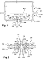
- Figure 1 illustrates an exemplary embodiment of a tank 300 comprising a first connector 100 attached to an electrical device 400, e.g. a heater, a pump, a sensor, etc.
- the first connector 100 comprises a plastic part 110 and two electrically conductive contact elements 121, 122 protruding out of a coupling side 120 of the plastic part 110.
- the first electrically conductive contact elements 121, 122 are electrically connected with the electrical device 400 via cables 131, 132 which are integrated in the plastic part 110 of first connector 100, wherein the cables 131, 132 are electrically connected to the first electrically conductive contact elements 121, 122, respectively.
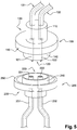
- First connector 100 is adapted to be coupled with a second connector 200, see figure 2 .
- the second connector 200 comprises a second plastic part 210 and two second electrically conductive contact elements 221, 222 protruding out of a coupling side 220 of the second connector 200.
- the two second electrically conductive contact elements 221, 222 are configured for being coupled with the first electrically conductive contact elements 121, 122, respectively.
- the first plastic part 110 is welded along a closed curve 150, e.g. along a ring surface, to a plastic portion inside the tank 300, here an inner side 350 of the tank surrounding a connector opening 330 in the tank 300.
- the closed curve 150 extends around, i.e. surrounds or includes, the first electrically conductive contact elements 121, 122.
- the tank 300 comprises a first shell 310 and a second shell 320 which are welded along a circumferential flange 311, 321 to form the tank 300.
- the welding along the closed curve 150 of the first connector 100 may be performed before the first and second shells 310, 320 of tank 300 are welded.
- the first connector 100 is welded to the inner side 350 of the tank by hot plate welding or by laser welding from the outside of the tank 300.
- the tank is preferably manufactured from a material which is transparent for the laser radiation
- the first plastic part 110 is preferably manufactured from a plastic material configured to absorb heat, e.g. a black plastic material.
- the first plastic part 110 is welded such that the electrically conductive contact elements 121, 122, protruding outward of the first plastic part 110, are accessible from the outside of the tank. More in particular, the first and second electrically conductive contact elements 121, 122 are protruding outwardly of the first plastic part 110 at a coupling side 120 of the first connector 100. At the other cable side 130 of the first connector 100, first and second cables 131, 132 power the electrical device 400.
- the connection cables 131, 132 have an end which is sealingly integrated in the first plastic part 110, and the two first electrically conductive contact elements 121, 122 are electrically connected inside the first plastic part 110 to the two connection wires of the two connection cables 131, 132.
- the two electrical cables 131, 132 may have a plastic sheath made of a thermoplastic polymer material that is compatible with the thermoplastic material of the plastic part 110 in the sense that polymer entanglements are created at the interface of the sheath and the plastic material.
- the sheath may be made e.g. of a polyamide material
- the thermoplastic plastic material may be e.g. a compatible poly-ethylene material optionally comprising a compound for increasing the polarity (e.g. PE grafted with maleic anhydride, PRIEX®), a polyamide material or a compatible polypropylene material.
- a polyethylene, grafted with an extra high content of maleic anhydride has the advantage that the grafted maleic anhydride introduces polarity to the polymer achieving compatibility between polyolefins and more polar materials or polymers like EVOH or Polyamide. More generally, the skilled person understands that many compatible materials exist for the sheath and the plastic part. There exist tables showing plastic welding compatibility (see e.g. www.lpkfusa.com/lq from the laser welding company LPFK). Such welding compatibility tables also provide a good indication of the compatibility of two materials (sheath material and plastic material of part to be formed) that are being overmoulded.
- first plastic part 110 of the first connector 100 comprises a first positioning element 140 at the coupling side 120
- second plastic part 210 of the second connector 200 has a corresponding positioning element 240 at the coupling side 220.
- first and second positioning elements 140, 240 may be e.g. cylindrical parts extending around the first and second contact elements 121, 122; 221, 222, and configured to cooperate in a telescopic manner. End parts of the positioning elements 140, 240 may be chamfered to further facilitate the guiding of the positioning elements 140, 240 with respect to each other.
- the second plastic portion 210 may be welded along a closed curve 250 to an outer side 360 of the tank 300.
- the electrically conductive coupling portions 121, 122; 221, 222 will be sealed from the outside avoiding e.g. moist penetration between the coupling sides 120, 220 of the first and second connector 100, 200.
- FIG. 3 illustrates schematically an example not belonging to the invention.
- the tank 300 has a flange opening 340 which is closed by a mounting flange 500.
- the first connector 100 has a first plastic part 110 which is welded along a closed curve 150 to the inner side 550 of the flange 500, around a connector opening 530 in the mounting flange 500.
- the first connector 100 is welded to the immersed side of the mounting flange 500.
- the first electrically conductive contact elements 121, 122 protrude outwardly of a coupling side 120 of the first connector 100, through the connector opening 530 in the mounting flange 500.
- the first connector 100 may be identical to the first connector 100 of the first exemplary embodiment of figures 1 and 2 , and may be connected in a similar manner to an electrical device 400.
- the second connector 200 is similar to the connector 200 of figure 2 , with this difference that the second plastic part 210 is not welded to the outward side 560 of the flange 500.
- the second connector 200 may be similar to the second connector 200 of figure 2 , and may be welded to the outer side 560 of the mounting flange 500.
- the second connector 200 may be part of an electronic unit mounted outside of the tank 300, e.g. on the outer side 560 of the mounting flange 500.
- the second connector 200 is integrated in a frame 800 attached to a cover 900. More in particular the second plastic part 210 of second connector 200 may be an integrated part of frame 800. Frame 800 may be connected to cover 900 by any type of suitable means, e.g. a snap-fit connection. A number of components 801, 802, 803, e.g. electronic components such as sensor or control parts, may be attached to the frame 800 and/or to the cover 900. Further, there may be provided a third connector 910 at a side wall of the cover 900 connected directly or indirectly to the second connector 200. In this embodiment the first connector 100 may be welded to an inner side 350 of a tank wall as in the embodiment of figure 1 or may be welded to an inner side 550 of a mounting flange, as in the embodiment of figure 3 .
- FIG. 4 illustrates schematically another exemplary embodiment of the invention.
- the tank 300 comprises two heaters 400, 600.
- a first connector is connected to the first heater 400 in the same manner as described above for electrical device 400.
- the second connector 200 is similar to the second connector of figure 2 .
- both the first and the second connector 100, 200 are located entirely within the tank 300, and an outer circumferential edge 150 of plastic part 110 of the first connector 100 is welded to an outer circumferential part 250 of second plastic part 210 of the second connector 200.
- the cables 231, 232 provided at the cable side 230 of the second connector 200 are an integral part of the second heater 600. In that way, the first and the second heater may be connected in series inside the tank.
- the connecting cables 231, 232 may be brought outside of the tank via any suitable cable connection piece 700. Also, there may be provided instead of connection piece 700, a further first and second connector 100, 200, as in the embodiment of figures 1 and 2 or figure 3 . In other words, there may be provided a first connector 100 coupled to a second connector 200 entirely within the tank, as well as a first connector 100 welded to an inner side of the tank around a connector opening in the tank.
- the first and second connector 100, 200 of figure 6 may be welded to an inner side of the tank, wherein connecting pins 121, 122 protrude outwardly of the tank.
- the first connector 100 comprises four wire end parts of cables 131, 132, 131', 132'.
- a first wire 131 e.g. connected to the first heater, and a first wire 131' e.g. connected to the second heater are both connected to a first contact pin 121.
- a second wire 132 e.g.
- first and second heater may be fed in parallel.
- first connectors 100, and two second connectors 200 in order to connect a first heater independently of a second heater.
- Figure 5 illustrates a perspective view of an exemplary embodiment of a first and second connector.
- the first plastic part 110 of the first connector 100 is shaped with a plurality of cylindrical parts
- the second connector 200 is shaped correspondingly with a plurality of cylindrical parts.
- the skilled person understands that the invention is not limited to connectors with a cylindrical shape, and that other shapes are equally possible, see e.g. the embodiment of figure 6 .
- the various components of the first and second connector 100, 200 have been discussed above in the various embodiments, and are not repeated.
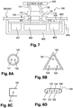
- the closed curve 150 may have various shapes as illustrated in figures 8A-8D .
- the closed curve 150 is part of a ring shaped surface surrounding two electrically conductive contact elements 121, 122, as in figure 1 .
- the closed curve 150 is part of a triangular shaped surface surrounding three electrically conductive contact elements 121, 122, 123.
- the closed curve 150 is a square surrounding one electrically conductive contact element 121.
- the closed curve 150 is an oval surrounding six electrically conductive contact elements 121, 122, 123, 124, 125, 126.
- Embodiments of the method of the invention allow obtaining a sealed interface for an electrical appliance arranged in a tank, e.g. in a urea tank, a diesel tank, a fuel tank, etc.
Landscapes
- Engineering & Computer Science (AREA)
- Chemical & Material Sciences (AREA)
- Combustion & Propulsion (AREA)
- Transportation (AREA)
- Mechanical Engineering (AREA)
- Life Sciences & Earth Sciences (AREA)
- Sustainable Development (AREA)
- Sustainable Energy (AREA)
- Connector Housings Or Holding Contact Members (AREA)
- Cooling, Air Intake And Gas Exhaust, And Fuel Tank Arrangements In Propulsion Units (AREA)
- Details Of Connecting Devices For Male And Female Coupling (AREA)
- Manufacturing Of Electrical Connectors (AREA)
Claims (10)
- Tank (300), der eine elektrische Vorrichtung (400) umfasst, die an einem ersten Verbinder (100) angebracht ist, wobei der erste Verbinder (100) so ausgebildet ist, dass er mit einem zweiten Verbinder (200) koppelbar ist, wobei der erste Verbinder (100) ein erstes Kunststoffteil (110) und zumindest ein erstes elektrisch leitendes Kontaktelement (121, 122) umfasst, wobei das zumindest eine erste elektrisch leitende Kontaktelement (121, 122) elektrisch mit der elektrischen Vorrichtung (400) verbunden ist, wobei der zweite Verbinder (200) ein zweites Kunststoffteil (210) und zumindest ein zweites elektrisch leitendes Kontaktelement (221, 222) umfasst, wobei das zumindest eine zweite elektrisch leitende Kontaktelement (221, 222) so ausgebildet ist, dass es mit dem zumindest einen ersten elektrisch leitenden Kontaktelement (121, 122) koppelbar ist, wobei das erste Kunststoffteil (110) entlang einer äußeren Umfangskante geschweißt ist, bei der es sich um einen geschlossenen Rand (150) handelt, die sich um das zumindest eine erste elektrisch leitende Kontaktelement (121, 122) herum erstreckt, an einen Kunststoffabschnitt im Inneren des Tanks (300), dadurch gekennzeichnet, dass
das zweite Kunststoffteil (210) einen äußeren umlaufenden Rand (250) aufweist, der angeschweißt ist:- an eine Außenseite (360) des Tanks (300), die eine Anschlussöffnung (330) umgibt; oder- am äußeren Umfangsrand (150) des ersten Kunststoffteils (110), wobei das zweite Kunststoffteil (210) des zweiten Verbindungsstücks (200) der Kunststoffabschnitt im Inneren des Tanks (300) ist. - Tank (300) nach Anspruch 1, wobei der erste Kunststoffteil (110) entlang einer geschlossenen Kurve mit dem zweiten Kunststoffteil (210) des zweiten Verbinders (200) um das zumindest eine erste (121, 122) und zweite (221, 222) elektrisch leitende Kontaktelement herum verschweißt ist.
- Tank (300) nach Anspruch 2, wobei der erste Verbinder (100) mit dem zweiten Verbinder (200) innerhalb des Tanks (300) gekoppelt ist und der erste (100) und der zweite Verbinder (200) vollständig innerhalb des Tanks (300) angeordnet sind.
- Tank (300) nach einem der vorhergehenden Ansprüche, wobei die elektrische Vorrichtung (400) zumindest ein Verbindungskabel (131, 132) umfasst, wobei das zumindest eine Verbindungskabel (131, 132) ein Ende aufweist, das abdichtend in das erste Kunststoffteil (110) integriert ist, und wobei das zumindest eine erste elektrisch leitende Kontaktelement (121, 122) elektrisch mit zumindest einem Verbindungsdraht des zumindest einen Verbindungskabels (131, 132) verbunden ist.
- Tank (300) nach einem der vorhergehenden Ansprüche, wobei die elektrische Vorrichtung (400) zwei Verbindungskabel (131, 132) umfasst, und wobei der erste Verbinder (100) zwei elektrisch leitende Kontaktelemente (121, 122) umfasst, die mit den zwei Verbindungskabeln (131, 132) im Inneren des ersten Kunststoffteils (110) verbunden sind.
- Tank (300) nach einem der vorhergehenden Ansprüche, wobei das zumindest eine erste (121, 122) oder zweite (221, 222) elektrisch leitende Kontaktelement zumindest einen Verbindungsstift umfasst, und wobei das zumindest eine zweite (221, 222) oder erste (121, 122) elektrisch leitende Kontaktelement zumindest einen Kontaktbus umfasst, der zur Aufnahme des zumindest einen Verbindungsstiftes dimensioniert ist.
- Tank (300) nach einem der vorstehenden Ansprüche, wobei das erste Kunststoffteil (110) ein erstes Positionierungselement (140) zwischen dem zumindest einen ersten elektrisch leitenden Kontaktelement (121, 122) und der geschlossene Rand (150) umfasst, und das zweite Kunststoffteil (210) ein zweites Positionierungselement (240) umfasst, das so ausgebildet ist, dass es mit dem ersten Positionierungselement (140) derart zusammenwirkt, dass die Positionierung des zweiten Verbinders (200) durch das erste (140) und das zweite (240) Positionierungselement geführt wird.
- Verfahren zum Anschließen einer elektrischen Vorrichtung (400) in einem Tank (300), umfassend:- Bereitstellen der elektrischen Vorrichtung (400) mit einem ersten Verbinder (100), wobei der erste Verbinder (100) ein erstes Kunststoffteil (110) und zumindest ein erstes elektrisch leitendes Kontaktelement 20 (121, 122) umfasst, das elektrisch mit der elektrischen Vorrichtung (400) verbunden ist;- Zusammenbau des Tanks (300), so dass das erste Kunststoffteil (110) entlang eines geschlossenen Rands (150) an einen Kunststoffabschnitt im Inneren des Tanks (300) geklebt wird und dass ein zweiter Verbinder (200) mit dem ersten Verbinder (100) gekoppelt wird, wobei der zweite Verbinder (200) ein zweites Kunststoffteil (210) und zumindest ein zweites elektrisch leitendes Kontaktelement (221, 222) umfasst, wobei das zumindest eine zweite elektrisch leitende Kontaktelement (221, 222), wobei mit dem zumindest einen ersten elektrisch leitenden Kontaktelement (121, 122) gekoppelt ist, wobei der Zusammenbau so erfolgt, dass das erste Kunststoffteil (110) entlang eines äußeren Rands (150), bei der es sich um eine geschlossene Kurve handelt, die sich um das zumindest eine erste elektrisch leitende Kontaktelement (121, 122) herum erstreckt, an den Kunststoffabschnitt im Inneren des Tanks (300) geschweißt wird, unddadurch gekennzeichnet, dass
das zweite Kunststoffteil (210) einen äußeren umlaufenden Rand (250) aufweist, an den es angeschweißt ist:- an einer Außenseite (360) des Tanks (300), die eine Anschlussöffnung (330) umgibt; oder- am äußeren Umfangsrand (150) des ersten Kunststoffteils (110), wobei das zweite Kunststoffteil (210) des zweiten Anschlusses (200) der Kunststoffabschnitt im Inneren des Tanks (300) ist. - Verfahren nach Anspruch 8, wobei der erste Kunststoffverbinder (100) durch Umspritzen eines Verbindungskabels mit dem Kunststoffmaterial und durch Verbinden des zumindest einen ersten elektrisch leitenden Kontaktelements (121, 122) mit einem Verbindungsdraht des Verbindungskabels (131, 132) hergestellt wird.
- Verfahren nach einem der Ansprüche 8-9, wobei der Zusammenbau des Tanks (300) umfasst:- Kleben des ersten Kunststoffteils (110) entlang einer geschlossenen Kurve an eine Innenseite (350) einer ersten Tankhülle (310),- Anbringen der ersten Tankhülle (310) an einer zweiten Tankhülle (320), so dass ein die elektrische Vorrichtung (400) umschließender Tank (300) gebildet wird, und- Kopplung des zweiten Anschlusses (200) mit dem ersten Anschluss (100).
Applications Claiming Priority (2)
| Application Number | Priority Date | Filing Date | Title |
|---|---|---|---|
| EP15306814.3A EP3168075A1 (de) | 2015-11-16 | 2015-11-16 | Tank mit einem steckverbinder und verfahren zum anschliessen einer elektrischen vorrichtung in einem tank |
| PCT/EP2016/077858 WO2017085125A1 (en) | 2015-11-16 | 2016-11-16 | Tank including a connector and method for connecting an electrical device in a tank |
Publications (2)
| Publication Number | Publication Date |
|---|---|
| EP3377355A1 EP3377355A1 (de) | 2018-09-26 |
| EP3377355B1 true EP3377355B1 (de) | 2020-07-01 |
Family
ID=54557351
Family Applications (2)
| Application Number | Title | Priority Date | Filing Date |
|---|---|---|---|
| EP15306814.3A Withdrawn EP3168075A1 (de) | 2015-11-16 | 2015-11-16 | Tank mit einem steckverbinder und verfahren zum anschliessen einer elektrischen vorrichtung in einem tank |
| EP16797875.8A Active EP3377355B1 (de) | 2015-11-16 | 2016-11-16 | Tank mit einem steckverbinder und verfahren zum anschliessen einer elektrischen vorrichtung in einem tank |
Family Applications Before (1)
| Application Number | Title | Priority Date | Filing Date |
|---|---|---|---|
| EP15306814.3A Withdrawn EP3168075A1 (de) | 2015-11-16 | 2015-11-16 | Tank mit einem steckverbinder und verfahren zum anschliessen einer elektrischen vorrichtung in einem tank |
Country Status (6)
| Country | Link |
|---|---|
| US (1) | US20180351288A1 (de) |
| EP (2) | EP3168075A1 (de) |
| JP (1) | JP2018535523A (de) |
| KR (1) | KR20180082514A (de) |
| CN (1) | CN108349377A (de) |
| WO (1) | WO2017085125A1 (de) |
Families Citing this family (4)
| Publication number | Priority date | Publication date | Assignee | Title |
|---|---|---|---|---|
| DE102017119707A1 (de) * | 2017-08-28 | 2019-02-28 | Kautex Textron Gmbh & Co. Kg | Flüssigkeitsbehälter und Verfahren zum Herstellen eines Flüssigkeitsbehälters |
| DE102017217819A1 (de) * | 2017-10-06 | 2019-04-11 | Kautex Textron Gmbh & Co. Kg | Flüssigkeitsbehälter für ein Kraftfahrzeug |
| US10787203B2 (en) * | 2018-01-03 | 2020-09-29 | Ford Global Technologies, Llc | Hybrid energy storage and delivery devices for hybrid electric vehicles |
| CN114624839B (zh) * | 2020-12-10 | 2024-03-08 | 宁波舜宇车载光学技术有限公司 | 结构件、镜头模组及其制造方法 |
Family Cites Families (10)
| Publication number | Priority date | Publication date | Assignee | Title |
|---|---|---|---|---|
| JP3020341B2 (ja) * | 1992-03-18 | 2000-03-15 | 松下冷機株式会社 | 気密端子保護カバー |
| ITTO20030230A1 (it) * | 2003-03-27 | 2004-09-28 | Fiat Ricerche | Organo connettore per collegamenti elettrici attraverso |
| US6966800B2 (en) * | 2004-03-22 | 2005-11-22 | Fci Americas Technology, Inc. | Overmolded electrical connector |
| FR2869842B1 (fr) * | 2004-05-07 | 2007-07-06 | Inergy Automotive Systems Res | Dispositif pour la fixation d'un composant sur un corps creux, methode de fixation associee, reservoir a carburant |
| DE102006031903A1 (de) * | 2006-07-07 | 2008-01-10 | Kautex Textron Gmbh & Co. Kg | Kraftstoffbehälter |
| JP4580994B2 (ja) * | 2008-02-07 | 2010-11-17 | 本田技研工業株式会社 | 高圧タンク |
| US9731593B2 (en) * | 2008-08-07 | 2017-08-15 | Ford Global Technologies, Llc | Fuel storage system |
| DE102009046954A1 (de) * | 2009-11-23 | 2011-05-26 | Robert Bosch Gmbh | Modulkonzept für die Komponenten eines Tanks zur Bevorratung eines Reduktionsmittels |
| EP2402198A1 (de) * | 2010-06-29 | 2012-01-04 | Inergy Automotive Systems Research (Société Anonyme) | Plastikbrennstofftank mit verbesserter Deformationsstabilität |
| JP6178673B2 (ja) * | 2013-08-29 | 2017-08-09 | 愛三工業株式会社 | 計測装置 |
-
2015
- 2015-11-16 EP EP15306814.3A patent/EP3168075A1/de not_active Withdrawn
-
2016
- 2016-11-16 EP EP16797875.8A patent/EP3377355B1/de active Active
- 2016-11-16 JP JP2018525474A patent/JP2018535523A/ja active Pending
- 2016-11-16 US US15/776,331 patent/US20180351288A1/en not_active Abandoned
- 2016-11-16 WO PCT/EP2016/077858 patent/WO2017085125A1/en not_active Ceased
- 2016-11-16 CN CN201680065245.XA patent/CN108349377A/zh active Pending
- 2016-11-16 KR KR1020187016113A patent/KR20180082514A/ko not_active Withdrawn
Non-Patent Citations (1)
| Title |
|---|
| None * |
Also Published As
| Publication number | Publication date |
|---|---|
| CN108349377A (zh) | 2018-07-31 |
| JP2018535523A (ja) | 2018-11-29 |
| EP3168075A1 (de) | 2017-05-17 |
| KR20180082514A (ko) | 2018-07-18 |
| EP3377355A1 (de) | 2018-09-26 |
| WO2017085125A1 (en) | 2017-05-26 |
| US20180351288A1 (en) | 2018-12-06 |
Similar Documents
| Publication | Publication Date | Title |
|---|---|---|
| EP3377355B1 (de) | Tank mit einem steckverbinder und verfahren zum anschliessen einer elektrischen vorrichtung in einem tank | |
| CA2263707C (en) | Weldable vapor vent valve for fuel tanks | |
| US7758084B2 (en) | Connection between a pipe and a wall | |
| US9366364B2 (en) | Connection between a wall and a pipe | |
| KR101381696B1 (ko) | 액체용 운반 및 저장 용기를 위한 태핑 피팅, 및 그러한 태핑 피팅을 가진 운반 및 저장 용기 | |
| AU2003248399A1 (en) | Pipe Connection | |
| DE102010062982A1 (de) | Tankeinbaumodul, Flüssigkeitstank | |
| CN110710340B (zh) | 用于电气设备的、具有紧密模制的壳体部件的壳体 | |
| CN105517831A (zh) | 带有内连接部件的储箱和用于组装这种储箱的方法 | |
| US8870229B2 (en) | System for connecting hose lines | |
| KR102052393B1 (ko) | 고온 내성을 갖는 계량 모듈 | |
| CN107921863A (zh) | 包括被紧固的构件的液体车辆储箱 | |
| EP3134715B1 (de) | Verbindungseinrichtung und verfahren zum herstellen einer verbindungseinrichtung | |
| US9295436B2 (en) | Method for manufacturing intraoral sensor | |
| US20150118915A1 (en) | Assembly for a prefabricated terminal block and method for producing prefabricated terminal blocks | |
| IE52528B1 (en) | Electrical plug connector and prefabricated insulating housing | |
| US10113675B2 (en) | Device for connecting two fluid-conducting lines | |
| US20180264936A1 (en) | Liquid tank with a radiator | |
| EP2903111A1 (de) | Verfahren zur Fixierung eines Kabels an einem Teil, Anordnung mit an einem Teil fixierten Kabel und Behälter mit einer solchen Anordnung | |
| KR20070077102A (ko) | 연료 탱크 구성품 및 그 제조 방법 | |
| WO1999030073A1 (en) | Connection between a wall and a pipe | |
| US10634273B2 (en) | Liquid transfer device and a tank assembly comprising such a transfer device | |
| EP4102048A1 (de) | Tankdeckel und kraftstofffördermodul | |
| CN109729736A (zh) | 用于座椅电动机保护的聚合物正温度系数装置 |
Legal Events
| Date | Code | Title | Description |
|---|---|---|---|
| STAA | Information on the status of an ep patent application or granted ep patent |
Free format text: STATUS: UNKNOWN |
|
| STAA | Information on the status of an ep patent application or granted ep patent |
Free format text: STATUS: THE INTERNATIONAL PUBLICATION HAS BEEN MADE |
|
| PUAI | Public reference made under article 153(3) epc to a published international application that has entered the european phase |
Free format text: ORIGINAL CODE: 0009012 |
|
| STAA | Information on the status of an ep patent application or granted ep patent |
Free format text: STATUS: REQUEST FOR EXAMINATION WAS MADE |
|
| 17P | Request for examination filed |
Effective date: 20180614 |
|
| AK | Designated contracting states |
Kind code of ref document: A1 Designated state(s): AL AT BE BG CH CY CZ DE DK EE ES FI FR GB GR HR HU IE IS IT LI LT LU LV MC MK MT NL NO PL PT RO RS SE SI SK SM TR |
|
| AX | Request for extension of the european patent |
Extension state: BA ME |
|
| DAV | Request for validation of the european patent (deleted) | ||
| DAX | Request for extension of the european patent (deleted) | ||
| RAP1 | Party data changed (applicant data changed or rights of an application transferred) |
Owner name: PLASTIC OMNIUM ADVANCED INNOVATION AND RESEARCH |
|
| GRAP | Despatch of communication of intention to grant a patent |
Free format text: ORIGINAL CODE: EPIDOSNIGR1 |
|
| STAA | Information on the status of an ep patent application or granted ep patent |
Free format text: STATUS: GRANT OF PATENT IS INTENDED |
|
| INTG | Intention to grant announced |
Effective date: 20200124 |
|
| GRAS | Grant fee paid |
Free format text: ORIGINAL CODE: EPIDOSNIGR3 |
|
| GRAA | (expected) grant |
Free format text: ORIGINAL CODE: 0009210 |
|
| STAA | Information on the status of an ep patent application or granted ep patent |
Free format text: STATUS: THE PATENT HAS BEEN GRANTED |
|
| AK | Designated contracting states |
Kind code of ref document: B1 Designated state(s): AL AT BE BG CH CY CZ DE DK EE ES FI FR GB GR HR HU IE IS IT LI LT LU LV MC MK MT NL NO PL PT RO RS SE SI SK SM TR |
|
| REG | Reference to a national code |
Ref country code: CH Ref legal event code: EP Ref country code: AT Ref legal event code: REF Ref document number: 1285847 Country of ref document: AT Kind code of ref document: T Effective date: 20200715 |
|
| REG | Reference to a national code |
Ref country code: IE Ref legal event code: FG4D |
|
| REG | Reference to a national code |
Ref country code: DE Ref legal event code: R096 Ref document number: 602016039207 Country of ref document: DE |
|
| REG | Reference to a national code |
Ref country code: LT Ref legal event code: MG4D |
|
| PG25 | Lapsed in a contracting state [announced via postgrant information from national office to epo] |
Ref country code: BG Free format text: LAPSE BECAUSE OF FAILURE TO SUBMIT A TRANSLATION OF THE DESCRIPTION OR TO PAY THE FEE WITHIN THE PRESCRIBED TIME-LIMIT Effective date: 20201001 |
|
| REG | Reference to a national code |
Ref country code: NL Ref legal event code: MP Effective date: 20200701 |
|
| REG | Reference to a national code |
Ref country code: AT Ref legal event code: MK05 Ref document number: 1285847 Country of ref document: AT Kind code of ref document: T Effective date: 20200701 |
|
| PG25 | Lapsed in a contracting state [announced via postgrant information from national office to epo] |
Ref country code: FI Free format text: LAPSE BECAUSE OF FAILURE TO SUBMIT A TRANSLATION OF THE DESCRIPTION OR TO PAY THE FEE WITHIN THE PRESCRIBED TIME-LIMIT Effective date: 20200701 Ref country code: HR Free format text: LAPSE BECAUSE OF FAILURE TO SUBMIT A TRANSLATION OF THE DESCRIPTION OR TO PAY THE FEE WITHIN THE PRESCRIBED TIME-LIMIT Effective date: 20200701 Ref country code: SE Free format text: LAPSE BECAUSE OF FAILURE TO SUBMIT A TRANSLATION OF THE DESCRIPTION OR TO PAY THE FEE WITHIN THE PRESCRIBED TIME-LIMIT Effective date: 20200701 Ref country code: ES Free format text: LAPSE BECAUSE OF FAILURE TO SUBMIT A TRANSLATION OF THE DESCRIPTION OR TO PAY THE FEE WITHIN THE PRESCRIBED TIME-LIMIT Effective date: 20200701 Ref country code: NO Free format text: LAPSE BECAUSE OF FAILURE TO SUBMIT A TRANSLATION OF THE DESCRIPTION OR TO PAY THE FEE WITHIN THE PRESCRIBED TIME-LIMIT Effective date: 20201001 Ref country code: GR Free format text: LAPSE BECAUSE OF FAILURE TO SUBMIT A TRANSLATION OF THE DESCRIPTION OR TO PAY THE FEE WITHIN THE PRESCRIBED TIME-LIMIT Effective date: 20201002 Ref country code: LT Free format text: LAPSE BECAUSE OF FAILURE TO SUBMIT A TRANSLATION OF THE DESCRIPTION OR TO PAY THE FEE WITHIN THE PRESCRIBED TIME-LIMIT Effective date: 20200701 Ref country code: CZ Free format text: LAPSE BECAUSE OF FAILURE TO SUBMIT A TRANSLATION OF THE DESCRIPTION OR TO PAY THE FEE WITHIN THE PRESCRIBED TIME-LIMIT Effective date: 20200701 Ref country code: PT Free format text: LAPSE BECAUSE OF FAILURE TO SUBMIT A TRANSLATION OF THE DESCRIPTION OR TO PAY THE FEE WITHIN THE PRESCRIBED TIME-LIMIT Effective date: 20201102 Ref country code: AT Free format text: LAPSE BECAUSE OF FAILURE TO SUBMIT A TRANSLATION OF THE DESCRIPTION OR TO PAY THE FEE WITHIN THE PRESCRIBED TIME-LIMIT Effective date: 20200701 |
|
| PG25 | Lapsed in a contracting state [announced via postgrant information from national office to epo] |
Ref country code: PL Free format text: LAPSE BECAUSE OF FAILURE TO SUBMIT A TRANSLATION OF THE DESCRIPTION OR TO PAY THE FEE WITHIN THE PRESCRIBED TIME-LIMIT Effective date: 20200701 Ref country code: LV Free format text: LAPSE BECAUSE OF FAILURE TO SUBMIT A TRANSLATION OF THE DESCRIPTION OR TO PAY THE FEE WITHIN THE PRESCRIBED TIME-LIMIT Effective date: 20200701 Ref country code: RS Free format text: LAPSE BECAUSE OF FAILURE TO SUBMIT A TRANSLATION OF THE DESCRIPTION OR TO PAY THE FEE WITHIN THE PRESCRIBED TIME-LIMIT Effective date: 20200701 Ref country code: IS Free format text: LAPSE BECAUSE OF FAILURE TO SUBMIT A TRANSLATION OF THE DESCRIPTION OR TO PAY THE FEE WITHIN THE PRESCRIBED TIME-LIMIT Effective date: 20201101 |
|
| PG25 | Lapsed in a contracting state [announced via postgrant information from national office to epo] |
Ref country code: NL Free format text: LAPSE BECAUSE OF FAILURE TO SUBMIT A TRANSLATION OF THE DESCRIPTION OR TO PAY THE FEE WITHIN THE PRESCRIBED TIME-LIMIT Effective date: 20200701 |
|
| REG | Reference to a national code |
Ref country code: DE Ref legal event code: R097 Ref document number: 602016039207 Country of ref document: DE |
|
| PG25 | Lapsed in a contracting state [announced via postgrant information from national office to epo] |
Ref country code: SM Free format text: LAPSE BECAUSE OF FAILURE TO SUBMIT A TRANSLATION OF THE DESCRIPTION OR TO PAY THE FEE WITHIN THE PRESCRIBED TIME-LIMIT Effective date: 20200701 Ref country code: EE Free format text: LAPSE BECAUSE OF FAILURE TO SUBMIT A TRANSLATION OF THE DESCRIPTION OR TO PAY THE FEE WITHIN THE PRESCRIBED TIME-LIMIT Effective date: 20200701 Ref country code: IT Free format text: LAPSE BECAUSE OF FAILURE TO SUBMIT A TRANSLATION OF THE DESCRIPTION OR TO PAY THE FEE WITHIN THE PRESCRIBED TIME-LIMIT Effective date: 20200701 Ref country code: RO Free format text: LAPSE BECAUSE OF FAILURE TO SUBMIT A TRANSLATION OF THE DESCRIPTION OR TO PAY THE FEE WITHIN THE PRESCRIBED TIME-LIMIT Effective date: 20200701 Ref country code: DK Free format text: LAPSE BECAUSE OF FAILURE TO SUBMIT A TRANSLATION OF THE DESCRIPTION OR TO PAY THE FEE WITHIN THE PRESCRIBED TIME-LIMIT Effective date: 20200701 |
|
| PLBE | No opposition filed within time limit |
Free format text: ORIGINAL CODE: 0009261 |
|
| STAA | Information on the status of an ep patent application or granted ep patent |
Free format text: STATUS: NO OPPOSITION FILED WITHIN TIME LIMIT |
|
| PG25 | Lapsed in a contracting state [announced via postgrant information from national office to epo] |
Ref country code: AL Free format text: LAPSE BECAUSE OF FAILURE TO SUBMIT A TRANSLATION OF THE DESCRIPTION OR TO PAY THE FEE WITHIN THE PRESCRIBED TIME-LIMIT Effective date: 20200701 |
|
| REG | Reference to a national code |
Ref country code: DE Ref legal event code: R119 Ref document number: 602016039207 Country of ref document: DE |
|
| 26N | No opposition filed |
Effective date: 20210406 |
|
| PG25 | Lapsed in a contracting state [announced via postgrant information from national office to epo] |
Ref country code: MC Free format text: LAPSE BECAUSE OF FAILURE TO SUBMIT A TRANSLATION OF THE DESCRIPTION OR TO PAY THE FEE WITHIN THE PRESCRIBED TIME-LIMIT Effective date: 20200701 Ref country code: SK Free format text: LAPSE BECAUSE OF FAILURE TO SUBMIT A TRANSLATION OF THE DESCRIPTION OR TO PAY THE FEE WITHIN THE PRESCRIBED TIME-LIMIT Effective date: 20200701 |
|
| REG | Reference to a national code |
Ref country code: CH Ref legal event code: PL |
|
| GBPC | Gb: european patent ceased through non-payment of renewal fee |
Effective date: 20201116 |
|
| PG25 | Lapsed in a contracting state [announced via postgrant information from national office to epo] |
Ref country code: LU Free format text: LAPSE BECAUSE OF NON-PAYMENT OF DUE FEES Effective date: 20201116 |
|
| REG | Reference to a national code |
Ref country code: BE Ref legal event code: MM Effective date: 20201130 |
|
| PG25 | Lapsed in a contracting state [announced via postgrant information from national office to epo] |
Ref country code: CH Free format text: LAPSE BECAUSE OF NON-PAYMENT OF DUE FEES Effective date: 20201130 Ref country code: SI Free format text: LAPSE BECAUSE OF FAILURE TO SUBMIT A TRANSLATION OF THE DESCRIPTION OR TO PAY THE FEE WITHIN THE PRESCRIBED TIME-LIMIT Effective date: 20200701 Ref country code: LI Free format text: LAPSE BECAUSE OF NON-PAYMENT OF DUE FEES Effective date: 20201130 |
|
| PG25 | Lapsed in a contracting state [announced via postgrant information from national office to epo] |
Ref country code: FR Free format text: LAPSE BECAUSE OF NON-PAYMENT OF DUE FEES Effective date: 20201130 Ref country code: IE Free format text: LAPSE BECAUSE OF NON-PAYMENT OF DUE FEES Effective date: 20201116 |
|
| PG25 | Lapsed in a contracting state [announced via postgrant information from national office to epo] |
Ref country code: GB Free format text: LAPSE BECAUSE OF NON-PAYMENT OF DUE FEES Effective date: 20201116 Ref country code: DE Free format text: LAPSE BECAUSE OF NON-PAYMENT OF DUE FEES Effective date: 20210601 |
|
| PG25 | Lapsed in a contracting state [announced via postgrant information from national office to epo] |
Ref country code: IS Free format text: LAPSE BECAUSE OF FAILURE TO SUBMIT A TRANSLATION OF THE DESCRIPTION OR TO PAY THE FEE WITHIN THE PRESCRIBED TIME-LIMIT Effective date: 20201101 Ref country code: TR Free format text: LAPSE BECAUSE OF FAILURE TO SUBMIT A TRANSLATION OF THE DESCRIPTION OR TO PAY THE FEE WITHIN THE PRESCRIBED TIME-LIMIT Effective date: 20200701 Ref country code: MT Free format text: LAPSE BECAUSE OF FAILURE TO SUBMIT A TRANSLATION OF THE DESCRIPTION OR TO PAY THE FEE WITHIN THE PRESCRIBED TIME-LIMIT Effective date: 20200701 Ref country code: CY Free format text: LAPSE BECAUSE OF FAILURE TO SUBMIT A TRANSLATION OF THE DESCRIPTION OR TO PAY THE FEE WITHIN THE PRESCRIBED TIME-LIMIT Effective date: 20200701 |
|
| PG25 | Lapsed in a contracting state [announced via postgrant information from national office to epo] |
Ref country code: MK Free format text: LAPSE BECAUSE OF FAILURE TO SUBMIT A TRANSLATION OF THE DESCRIPTION OR TO PAY THE FEE WITHIN THE PRESCRIBED TIME-LIMIT Effective date: 20200701 |
|
| PG25 | Lapsed in a contracting state [announced via postgrant information from national office to epo] |
Ref country code: BE Free format text: LAPSE BECAUSE OF NON-PAYMENT OF DUE FEES Effective date: 20201130 |