EP3377416B1 - Réceptacle en matière plastique - Google Patents
Réceptacle en matière plastique Download PDFInfo
- Publication number
- EP3377416B1 EP3377416B1 EP16808925.8A EP16808925A EP3377416B1 EP 3377416 B1 EP3377416 B1 EP 3377416B1 EP 16808925 A EP16808925 A EP 16808925A EP 3377416 B1 EP3377416 B1 EP 3377416B1
- Authority
- EP
- European Patent Office
- Prior art keywords
- container
- side wall
- side walls
- profile
- reinforcing profile
- Prior art date
- Legal status (The legal status is an assumption and is not a legal conclusion. Google has not performed a legal analysis and makes no representation as to the accuracy of the status listed.)
- Active
Links
Images






Classifications
-
- B—PERFORMING OPERATIONS; TRANSPORTING
- B65—CONVEYING; PACKING; STORING; HANDLING THIN OR FILAMENTARY MATERIAL
- B65D—CONTAINERS FOR STORAGE OR TRANSPORT OF ARTICLES OR MATERIALS, e.g. BAGS, BARRELS, BOTTLES, BOXES, CANS, CARTONS, CRATES, DRUMS, JARS, TANKS, HOPPERS, FORWARDING CONTAINERS; ACCESSORIES, CLOSURES, OR FITTINGS THEREFOR; PACKAGING ELEMENTS; PACKAGES
- B65D11/00—Containers having bodies formed by interconnecting or uniting two or more rigid, or substantially rigid, components made wholly or mainly of plastics material
- B65D11/18—Containers having bodies formed by interconnecting or uniting two or more rigid, or substantially rigid, components made wholly or mainly of plastics material collapsible, i.e. with walls hinged together or detachably connected
- B65D11/1833—Containers having bodies formed by interconnecting or uniting two or more rigid, or substantially rigid, components made wholly or mainly of plastics material collapsible, i.e. with walls hinged together or detachably connected whereby all side walls are hingedly connected to the base panel
-
- B—PERFORMING OPERATIONS; TRANSPORTING
- B65—CONVEYING; PACKING; STORING; HANDLING THIN OR FILAMENTARY MATERIAL
- B65D—CONTAINERS FOR STORAGE OR TRANSPORT OF ARTICLES OR MATERIALS, e.g. BAGS, BARRELS, BOTTLES, BOXES, CANS, CARTONS, CRATES, DRUMS, JARS, TANKS, HOPPERS, FORWARDING CONTAINERS; ACCESSORIES, CLOSURES, OR FITTINGS THEREFOR; PACKAGING ELEMENTS; PACKAGES
- B65D1/00—Rigid or semi-rigid containers having bodies formed in one piece, e.g. by casting metallic material, by moulding plastics, by blowing vitreous material, by throwing ceramic material, by moulding pulped fibrous material or by deep-drawing operations performed on sheet material
- B65D1/34—Trays or like shallow containers
-
- B—PERFORMING OPERATIONS; TRANSPORTING
- B65—CONVEYING; PACKING; STORING; HANDLING THIN OR FILAMENTARY MATERIAL
- B65D—CONTAINERS FOR STORAGE OR TRANSPORT OF ARTICLES OR MATERIALS, e.g. BAGS, BARRELS, BOTTLES, BOXES, CANS, CARTONS, CRATES, DRUMS, JARS, TANKS, HOPPERS, FORWARDING CONTAINERS; ACCESSORIES, CLOSURES, OR FITTINGS THEREFOR; PACKAGING ELEMENTS; PACKAGES
- B65D11/00—Containers having bodies formed by interconnecting or uniting two or more rigid, or substantially rigid, components made wholly or mainly of plastics material
- B65D11/20—Details of walls made of plastics material
- B65D11/22—Reinforcing for strengthening parts of members
-
- B—PERFORMING OPERATIONS; TRANSPORTING
- B65—CONVEYING; PACKING; STORING; HANDLING THIN OR FILAMENTARY MATERIAL
- B65D—CONTAINERS FOR STORAGE OR TRANSPORT OF ARTICLES OR MATERIALS, e.g. BAGS, BARRELS, BOTTLES, BOXES, CANS, CARTONS, CRATES, DRUMS, JARS, TANKS, HOPPERS, FORWARDING CONTAINERS; ACCESSORIES, CLOSURES, OR FITTINGS THEREFOR; PACKAGING ELEMENTS; PACKAGES
- B65D11/00—Containers having bodies formed by interconnecting or uniting two or more rigid, or substantially rigid, components made wholly or mainly of plastics material
- B65D11/20—Details of walls made of plastics material
- B65D11/22—Reinforcing for strengthening parts of members
- B65D11/26—Local reinforcements, e.g. adjacent to closures
-
- B—PERFORMING OPERATIONS; TRANSPORTING
- B65—CONVEYING; PACKING; STORING; HANDLING THIN OR FILAMENTARY MATERIAL
- B65D—CONTAINERS FOR STORAGE OR TRANSPORT OF ARTICLES OR MATERIALS, e.g. BAGS, BARRELS, BOTTLES, BOXES, CANS, CARTONS, CRATES, DRUMS, JARS, TANKS, HOPPERS, FORWARDING CONTAINERS; ACCESSORIES, CLOSURES, OR FITTINGS THEREFOR; PACKAGING ELEMENTS; PACKAGES
- B65D11/00—Containers having bodies formed by interconnecting or uniting two or more rigid, or substantially rigid, components made wholly or mainly of plastics material
- B65D11/20—Details of walls made of plastics material
- B65D11/22—Reinforcing for strengthening parts of members
- B65D11/28—Metal reinforcements, e.g. metal frames
-
- B—PERFORMING OPERATIONS; TRANSPORTING
- B65—CONVEYING; PACKING; STORING; HANDLING THIN OR FILAMENTARY MATERIAL
- B65D—CONTAINERS FOR STORAGE OR TRANSPORT OF ARTICLES OR MATERIALS, e.g. BAGS, BARRELS, BOTTLES, BOXES, CANS, CARTONS, CRATES, DRUMS, JARS, TANKS, HOPPERS, FORWARDING CONTAINERS; ACCESSORIES, CLOSURES, OR FITTINGS THEREFOR; PACKAGING ELEMENTS; PACKAGES
- B65D21/00—Nestable, stackable or joinable containers; Containers of variable capacity
- B65D21/02—Containers specially shaped, or provided with fittings or attachments, to facilitate nesting, stacking, or joining together
-
- B—PERFORMING OPERATIONS; TRANSPORTING
- B65—CONVEYING; PACKING; STORING; HANDLING THIN OR FILAMENTARY MATERIAL
- B65D—CONTAINERS FOR STORAGE OR TRANSPORT OF ARTICLES OR MATERIALS, e.g. BAGS, BARRELS, BOTTLES, BOXES, CANS, CARTONS, CRATES, DRUMS, JARS, TANKS, HOPPERS, FORWARDING CONTAINERS; ACCESSORIES, CLOSURES, OR FITTINGS THEREFOR; PACKAGING ELEMENTS; PACKAGES
- B65D21/00—Nestable, stackable or joinable containers; Containers of variable capacity
- B65D21/02—Containers specially shaped, or provided with fittings or attachments, to facilitate nesting, stacking, or joining together
- B65D21/0209—Containers specially shaped, or provided with fittings or attachments, to facilitate nesting, stacking, or joining together stackable or joined together one-upon-the-other in the upright or upside-down position
- B65D21/0212—Containers presenting local stacking elements protruding from the upper or lower edge of a side wall, e.g. handles, lugs, ribs, grooves
-
- B—PERFORMING OPERATIONS; TRANSPORTING
- B65—CONVEYING; PACKING; STORING; HANDLING THIN OR FILAMENTARY MATERIAL
- B65D—CONTAINERS FOR STORAGE OR TRANSPORT OF ARTICLES OR MATERIALS, e.g. BAGS, BARRELS, BOTTLES, BOXES, CANS, CARTONS, CRATES, DRUMS, JARS, TANKS, HOPPERS, FORWARDING CONTAINERS; ACCESSORIES, CLOSURES, OR FITTINGS THEREFOR; PACKAGING ELEMENTS; PACKAGES
- B65D21/00—Nestable, stackable or joinable containers; Containers of variable capacity
- B65D21/02—Containers specially shaped, or provided with fittings or attachments, to facilitate nesting, stacking, or joining together
- B65D21/0209—Containers specially shaped, or provided with fittings or attachments, to facilitate nesting, stacking, or joining together stackable or joined together one-upon-the-other in the upright or upside-down position
- B65D21/0213—Containers presenting a continuous stacking profile along the upper or lower edge of at least two opposite side walls
-
- B—PERFORMING OPERATIONS; TRANSPORTING
- B65—CONVEYING; PACKING; STORING; HANDLING THIN OR FILAMENTARY MATERIAL
- B65D—CONTAINERS FOR STORAGE OR TRANSPORT OF ARTICLES OR MATERIALS, e.g. BAGS, BARRELS, BOTTLES, BOXES, CANS, CARTONS, CRATES, DRUMS, JARS, TANKS, HOPPERS, FORWARDING CONTAINERS; ACCESSORIES, CLOSURES, OR FITTINGS THEREFOR; PACKAGING ELEMENTS; PACKAGES
- B65D85/00—Containers, packaging elements or packages, specially adapted for particular articles or materials
- B65D85/30—Containers, packaging elements or packages, specially adapted for particular articles or materials for articles particularly sensitive to damage by shock or pressure
- B65D85/34—Containers, packaging elements or packages, specially adapted for particular articles or materials for articles particularly sensitive to damage by shock or pressure for fruit, e.g. apples, oranges or tomatoes
-
- B—PERFORMING OPERATIONS; TRANSPORTING
- B65—CONVEYING; PACKING; STORING; HANDLING THIN OR FILAMENTARY MATERIAL
- B65D—CONTAINERS FOR STORAGE OR TRANSPORT OF ARTICLES OR MATERIALS, e.g. BAGS, BARRELS, BOTTLES, BOXES, CANS, CARTONS, CRATES, DRUMS, JARS, TANKS, HOPPERS, FORWARDING CONTAINERS; ACCESSORIES, CLOSURES, OR FITTINGS THEREFOR; PACKAGING ELEMENTS; PACKAGES
- B65D2205/00—Venting means
- B65D2205/02—Venting holes
-
- B—PERFORMING OPERATIONS; TRANSPORTING
- B65—CONVEYING; PACKING; STORING; HANDLING THIN OR FILAMENTARY MATERIAL
- B65D—CONTAINERS FOR STORAGE OR TRANSPORT OF ARTICLES OR MATERIALS, e.g. BAGS, BARRELS, BOTTLES, BOXES, CANS, CARTONS, CRATES, DRUMS, JARS, TANKS, HOPPERS, FORWARDING CONTAINERS; ACCESSORIES, CLOSURES, OR FITTINGS THEREFOR; PACKAGING ELEMENTS; PACKAGES
- B65D2519/00—Pallets or like platforms, with or without side walls, for supporting loads to be lifted or lowered
- B65D2519/00004—Details relating to pallets
- B65D2519/00009—Materials
- B65D2519/00014—Materials for the load supporting surface
- B65D2519/00034—Plastic
-
- B—PERFORMING OPERATIONS; TRANSPORTING
- B65—CONVEYING; PACKING; STORING; HANDLING THIN OR FILAMENTARY MATERIAL
- B65D—CONTAINERS FOR STORAGE OR TRANSPORT OF ARTICLES OR MATERIALS, e.g. BAGS, BARRELS, BOTTLES, BOXES, CANS, CARTONS, CRATES, DRUMS, JARS, TANKS, HOPPERS, FORWARDING CONTAINERS; ACCESSORIES, CLOSURES, OR FITTINGS THEREFOR; PACKAGING ELEMENTS; PACKAGES
- B65D2519/00—Pallets or like platforms, with or without side walls, for supporting loads to be lifted or lowered
- B65D2519/00004—Details relating to pallets
- B65D2519/00009—Materials
- B65D2519/00049—Materials for the base surface
- B65D2519/00069—Plastic
-
- B—PERFORMING OPERATIONS; TRANSPORTING
- B65—CONVEYING; PACKING; STORING; HANDLING THIN OR FILAMENTARY MATERIAL
- B65D—CONTAINERS FOR STORAGE OR TRANSPORT OF ARTICLES OR MATERIALS, e.g. BAGS, BARRELS, BOTTLES, BOXES, CANS, CARTONS, CRATES, DRUMS, JARS, TANKS, HOPPERS, FORWARDING CONTAINERS; ACCESSORIES, CLOSURES, OR FITTINGS THEREFOR; PACKAGING ELEMENTS; PACKAGES
- B65D2519/00—Pallets or like platforms, with or without side walls, for supporting loads to be lifted or lowered
- B65D2519/00004—Details relating to pallets
- B65D2519/00009—Materials
- B65D2519/00119—Materials for the construction of the reinforcements
- B65D2519/00129—Metal
-
- B—PERFORMING OPERATIONS; TRANSPORTING
- B65—CONVEYING; PACKING; STORING; HANDLING THIN OR FILAMENTARY MATERIAL
- B65D—CONTAINERS FOR STORAGE OR TRANSPORT OF ARTICLES OR MATERIALS, e.g. BAGS, BARRELS, BOTTLES, BOXES, CANS, CARTONS, CRATES, DRUMS, JARS, TANKS, HOPPERS, FORWARDING CONTAINERS; ACCESSORIES, CLOSURES, OR FITTINGS THEREFOR; PACKAGING ELEMENTS; PACKAGES
- B65D2519/00—Pallets or like platforms, with or without side walls, for supporting loads to be lifted or lowered
- B65D2519/00004—Details relating to pallets
- B65D2519/00009—Materials
- B65D2519/00154—Materials for the side walls
- B65D2519/00174—Plastic
-
- B—PERFORMING OPERATIONS; TRANSPORTING
- B65—CONVEYING; PACKING; STORING; HANDLING THIN OR FILAMENTARY MATERIAL
- B65D—CONTAINERS FOR STORAGE OR TRANSPORT OF ARTICLES OR MATERIALS, e.g. BAGS, BARRELS, BOTTLES, BOXES, CANS, CARTONS, CRATES, DRUMS, JARS, TANKS, HOPPERS, FORWARDING CONTAINERS; ACCESSORIES, CLOSURES, OR FITTINGS THEREFOR; PACKAGING ELEMENTS; PACKAGES
- B65D2519/00—Pallets or like platforms, with or without side walls, for supporting loads to be lifted or lowered
- B65D2519/00004—Details relating to pallets
- B65D2519/00009—Materials
- B65D2519/00223—Materials for the corner elements or corner frames
- B65D2519/00243—Plastic
-
- B—PERFORMING OPERATIONS; TRANSPORTING
- B65—CONVEYING; PACKING; STORING; HANDLING THIN OR FILAMENTARY MATERIAL
- B65D—CONTAINERS FOR STORAGE OR TRANSPORT OF ARTICLES OR MATERIALS, e.g. BAGS, BARRELS, BOTTLES, BOXES, CANS, CARTONS, CRATES, DRUMS, JARS, TANKS, HOPPERS, FORWARDING CONTAINERS; ACCESSORIES, CLOSURES, OR FITTINGS THEREFOR; PACKAGING ELEMENTS; PACKAGES
- B65D2581/00—Containers, packaging elements, or packages, for contents presenting particular transport or storage problems, or adapted to be used for non-packaging purposes after removal of contents
- B65D2581/02—Containers, packaging elements, or packages, for contents presenting particular transport or storage problems, or adapted to be used for non-packaging purposes after removal of contents specially adapted to protect contents from mechanical damage
Definitions
- the invention relates to containers made of plastic, with a rectangular bottom and four side walls, the bottom having a first stacking contour on the underside on its outer edge, the side walls having a second stacking contour at their upper edge region, and wherein when stacking containers one above the other the first stacking contour upper container and the second stack contour of a lower container in a centering engagement with each other.
- U1 is a container according to the preamble of claim 1 for the transport and storage of goods is known, with a rectangular bottom and with four projecting, rigid or foldable side walls, the bottom underside stacking edges and the side walls each having a stacking surface, wherein the stacking edges and the stacking surfaces are designed to allow several containers to be stacked one on top of the other.
- the side walls In containers for sensitive goods, such as fruit, the side walls should be as flexible as possible to avoid pressure points on the goods. On the other hand, this flexibility of the side walls leads to the problem of an increased risk of bulging of the upper edge of the side walls of lower, heavily loaded containers in a stack of loaded containers, which makes the stack unstable.
- Containers with a reinforced upper edge area are also known.
- DE 20 006 094 U1 describes a plastic container with a snap-on lid, in which at least one inward and / or at the edge of the container on the side of the container facing the top of the container for the lid and / or radially protruding reinforcing rib is formed on the outside and extends at least over a partial circumference of the container.
- the reinforcing rib also stabilizes the top edge of the container and thus the sealing area between the container and the lid.
- the reinforcing rib is molded onto the side wall, it is made of the same material as the rest of the side wall, so that if the side wall itself consists of a plastic which has a certain flexibility or flexibility, the reinforcing effect of the reinforcing rib is only slight.
- the document DE 296 01 187 U1 shows a load carrier made of foam, in particular of particle foam, with at least one stacking edge, and deals with the problem of increasing the load-bearing capacity.
- a stiffening profile is provided on at least part of the stack edge.
- foam load carriers require relatively thick walls, although only a low mechanical load-bearing capacity and a relatively small usable volume relative to the external dimensions are achieved. The use of such charge carriers is limited to applications with only low mechanical and thermal loads.
- a stackable packaging in particular made of foamed material, which has an outer wall with an upper edge and with a support on the underside, next to which there are side stops on the inside, with packaging stacked adjacent to one another with the upper edge of the lower packaging and the underside support of the upper packaging lie on top of each other and the side stops in this stacking position are on the inside next to the top edge of the lower packaging.
- the support surface of the top edge is designed to rise at least over a partial area of its transverse extent to the inner side stop side and that the bottom support has an approximately corresponding counter-shaping.
- the outer edge of the outer wall can have a wall reinforcement profile, the upper side of which forms the support surface for the support of a stacked, adjacent packaging.
- the wall reinforcement profile can be designed as a profile that can be plugged onto the upper edge of the outer wall, preferably with an approximately U-shaped cross section.
- the object of the present invention is therefore to create containers of the type mentioned at the outset which have a high level of mechanical stability and resilience, which can have side walls with a certain degree of flexibility to protect the goods in the container and which securely stack loaded containers one above the other guarantee.
- a first solution to the problem is achieved according to the invention with a container of the type mentioned at the outset, which is characterized in that the upper edge region of at least two opposite side walls is reinforced by at least one form-fitting and / or non-positive reinforcement profile attached to the other side wall, and that / Each reinforcing profile has on its upper side facing away from the container at least one profile web running in the longitudinal direction of the reinforcing profile and forming a slideway for a further container to be fitted.
- two or more side walls of the container are reinforced with a reinforcing profile, the material of which differs from that of the side wall.
- a particularly large reinforcement effect can be achieved.
- the side walls of the container which are particularly stressed when containers are stacked one above the other, can thus be stabilized with relatively little technical effort so that bulging of the upper edge of loaded containers in the container stack can be ruled out with the usual stack heights and loads.
- the side walls themselves can advantageously have a certain flexibility which is gentle on the goods in the container.
- the / each reinforcement profile has on its upper side facing away from the container at least one profile web which runs in the longitudinal direction of the reinforcement profile and forms a slideway for a further container to be put on. It is therefore sufficient to initially place an upper container on a lower container with only a partial overlap, and then to place the upper container to move along the slideway of the lower container to its final stacking position.
- the reinforcement profile is attached to the rest of the side wall in a positive and / or non-positive manner.
- the / each reinforcement profile in a lower region facing the side wall has a groove which is open towards the bottom or a web pointing downwards, and that at the upper edge of the other side wall there is a web or an upwardly open groove is formed and that the reinforcement profile is latched or clamped or pushed onto the web of the side wall with its groove or is engaged or clamped or pushed into the groove of the side wall with its web.
- the reinforcement profile is thus connected to the associated side wall from above when the container is manufactured.
- the container that the upper edge region of two mutually opposite, longer side walls is reinforced by a reinforcing profile that extends over the length of the associated side wall. This effectively counteracts the naturally greater risk of bulging in the longer side walls.
- the side walls themselves consist of an unreinforced thermoplastic and that the / each reinforcement profile consists of a fiber-reinforced plastic or of metal.
- the side walls per se or the container itself can therefore be made from a relatively inexpensive material, in particular as injection molded parts.
- the reinforcement profiles can be made from a more stable material.
- the fiber-reinforced plastic is preferably reinforced with glass, carbon or natural fibers, from which the reinforcement profile can also advantageously be produced by injection molding.
- a further embodiment provides that sections of the stacking contour of the base below the side walls having the slideways are each designed with a groove, that the slideways and grooves are each designed such that when an upper container is placed on it on a lower container in a position offset relative to one another in the longitudinal direction of the slideways and grooves, the upper container slidably stands in an elevated position on the slideways of the lower container and that when or after the upper container is moved into a position congruent with the lower container Enter the slides in a stack end position while lowering the upper container.
- the container in this configuration offers several advantages.
- an upper container to be placed on a lower container with an offset of the containers relative to one another and a subsequent displacement of the upper container on the lower container into the congruent stacking position, which in particular means manual stacking of the containers, especially in their loaded state Handling personnel relieved.
- the upper container When the upper container is pushed onto the container below it, the upper container first slides in an elevated position on the slideways of the lower container and only lowers into its end-of-stack position at the end of the displacement process.
- a larger or larger space between the two is advantageous when pushed on Containers, specifically between the goods to be transported, such as fruit, in the lower container on one side and the underside of the bottom of the upper container on the other side. In this way, sensitive goods in the lower container, in particular fruit, which protrude slightly above the container edge, are not damaged by rubbing or scratching.
- each slideway is stepped or beveled or rounded at its end regions.
- slideways on two long side walls are useful for the practical use of the containers.
- slideways can be provided on two short side walls.
- the two side walls not having the slideways each have one or more spaced apart from one another in the longitudinal direction of these side walls, a conventional container placed on a container according to the invention, against shifting into Have cusps securing the longitudinal direction of the slideways, the height of which corresponds to the height of the slideways.
- the Figure 1 the drawing shows a container 1 with a bottom 2, with two mutually opposite first, longer side walls 3 and with two opposing second, shorter side walls 4, viewed obliquely from above.
- the container 1 is designed here as a folding container, in which the side walls 3, 4 are articulated to the bottom 2, so that they are between the in Figure 1 shown, upright use position and a rest position in which the four side walls 3, 4 are folded inwards on the floor 2, is adjustable.
- the side walls 3, 4 are each provided in a manner known per se with a handle opening 31, 41 and with releasable locking means 43 for mutually locking the side walls 3, 4 in their use position.
- the bottom 2 and the side walls 3, 4 are injection molded parts made of a thermoplastic material, at least the side walls 3 having flexible wall areas 33 with a certain flexibility in order to protect goods stored or transported in the container 1.
- the reinforcement profiles 5 consist of a material, in particular of fiber-reinforced plastic or of metal, which is more stable than the material from which the side walls 3 are made, usually an unreinforced plastic.
- the reinforcement profiles 5 thus ensure that the side walls 3 have a particularly high stability in their upper edge region, as a result of which undesired bulging of the upper edge of the side walls 3 in a stack of containers is avoided.
- Each reinforcing profile 5 has an upward-facing profile web 50 which extends in the longitudinal direction of the reinforcing profile 5 and the associated side wall 3.
- the profile webs 50 form on their upper side a slideway 11 on which an upper container 1 on a lower container 1 after only partially overlaying can be easily moved into its final stacking position.
- the end regions 12 of the slideway 11 are chamfered in order to shift the upper container 1 in a position elevated relative to the lower container 1 and to lower the upper container 1 relative to the lower container 1 only immediately before or when the congruent position of the upper container 1 is reached. As a result, the goods in the lower container 1 are protected from damage by pushing on the upper container 1.
- two protruding bumps 44 are formed on the upper edge of the shorter side walls 4 formed by the upper stack contour 40 at a distance from one another. These humps 44 block a conventional container placed on the container 1 against unwanted displacement along the slideways 11 beyond a congruent stacking position relative to the container 1 arranged below.
- Figure 2 shows the container 1 Figure 1 in frontal view of one of the longer side walls 3 with the reinforcing profile 5 attached to it Figure 2 the bottom 2 with its stacking contour 20 is visible.
- the reinforcement profile 5 is connected to the side wall 3.
- Beneath a central section of the reinforcing profile 5 is the handle opening 31 in the side wall 3.
- a central surface area of the side wall 3 bordered by the four edge areas of the side wall 3 forms the flexible wall area 33, which has a certain flexibility.
- its profile web 50 is visible, which forms the stacking contour 30 of the side wall 3 and one of the slideways 11 with the beveled slideway end regions 12.
- Figure 3 shows one of the longer side walls 3 and a reinforcing profile 5 not yet attached, in a view obliquely from above.
- the side wall 3 has on its upper edge an upwardly pointing web 35, on which locking elements 34 in the form of locking lugs protruding from the surface of the web are formed at regular intervals.
- the reinforcement profile 5 shown above the side wall 3, not yet connected to it, has on its underside a groove 53 with which the reinforcement profile 5 can be positively fitted onto the web 35 from top to bottom in the vertical direction.
- locking profile 5 is locked in a reliable manner, but can be detached if necessary, with the locking elements 34 on the side wall 3, thereby achieving the desired reinforcement and stiffening of the upper edge area of the side wall 3.
- Figure 4 shows a part of the longer side wall 3 and the reinforcement profile 5 now associated therewith Figure 3 in an enlarged detail view. Bottom left in Figure 4 part of the side wall 3 with the handle opening 31 is visible. The reinforcement profile 5 runs over it.
- One of the pairs of locking elements 34, 54 is visible to the right above the grip opening 31, the locking element 34 of the side wall 3 having the shape of a locking lug, which engages in the locking element 54 of the reinforcing profile 5 which is designed as a locking opening.
- the reinforcing profile 5 has, on its side facing the inside of the container, a plurality of parallel lateral profile wings 51 which make the reinforcing profile 5 particularly rigid with relatively little use of material.
- Figure 5 shows part of the longer side wall 3 and the associated reinforcement profile 5 in an enlarged view, partly in view and partly in a first vertical section.
- On the right in Figure 5 lying cut surface can be seen how the reinforcing profile 5 with its groove 53 is positively placed on the web 35 on the upper edge of the side wall 3.
- the reinforcing profile 5 also has lateral profile wings 51 running parallel to one another in the longitudinal direction of the reinforcing profile 5 on its surface facing away from the viewer and pointing towards the interior of the container for effective stiffening.
- Figure 6 shows part of the longer side wall 3 and the associated reinforcing profile 5 in an enlarged view, partly in view and partly in a second vertical section.
- the section here runs through one of the pairs of locking elements 34, 54, so that their interaction can be seen particularly clearly here.
- Figure 7 shows a container 1, each with a reinforcement profile 5 on two opposite, longer side walls 3, in view of a shorter side wall 4. Left and right in Figure 7 is therefore one of the two longer side walls 3 below Figure 7 the bottom 2 lies with its underside stacking contour 20.
- the container 1 on the shorter side wall 4 facing the viewer has the stacking contour 40 forming its upper edge.
- a handle opening 41 is offset in the transverse center of the side wall 4.
- two resilient locking means 43 which can be displaced in the horizontal direction, run parallel to the surface of the side wall 42.
- two upwardly protruding bumps 44 are molded, which serve to secure a conventional container of the same base dimensions placed on the container 1 in its congruent stacking position relative to the container 1 and to prevent the upper, conventional container from being moved along the slideways 11 from the congruent stacking position.
- the stack contours 30 are each formed here by one of the reinforcement profiles 5 which are snapped onto the rest of the side wall 3 at the top and each have a longitudinally extending profile web 50 on the upper side, the top side of which each forms a slideway 11.
- the bottom 2 points to its in Figure 7 on the left and right perpendicular to the plane of the longitudinal sides downwardly open grooves 21 which are arranged congruent to the profile webs 50. If an identical further container 1 is initially placed on the container 1 with an offset in the longitudinal direction of the slideways 11, the upper container 1 can be moved by means of its grooves 21 on the slideways 11 of the lower container 1 in an elevated position during the shifting to one with the lower container 1 congruent stack end position are moved, in which the upper container 1 relative to the lower container 1 then sinks into its final stacking position by cooperation of the appropriately designed slideways 11 and grooves 21.
- Figure 8 shows a further container 1, each with a reinforcement profile 5 on two opposite, longer side walls 3, in an oblique view from above.
- the reinforcement profiles 5 as insert parts, which are inserted as prefabricated parts in the manufacture of the container 1 or its side walls 3 in an injection mold, in which the remaining side wall is then injected, whereby the reinforcement profiles 5 are securely connected to the respective other side wall 3 become.
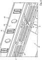
- the slideways 11 on the top of the stack contours 30 of the longer side walls 3 are not part of the reinforcement profiles 5 here, but part of the other side walls 3 and in each case formed on the top of a web 35 integral with the side wall 3.
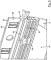
- Figure 9 shows one of the longer side walls 3 of the container Figure 8 and separately an associated reinforcement profile 5, in a view obliquely from above.
- the reinforcing profile 5 has two longitudinal webs 55 running parallel to one another and in the longitudinal direction of the reinforcing profile 5, as well as several transverse webs 56 connecting them to one another and spaced apart in the longitudinal direction.
- the plastic material of the other side wall 3 surrounds the transverse webs 56 of the reinforcing profile 5, whereby this is securely connected to the rest of the side wall 3.
- Figure 10 shows the side wall Figure 9 with the associated reinforcement profile 5, again in an oblique view from above. It can be seen here in particular that the reinforcement profile 5 runs below the slideway 11 and, with its upper side, forms part of the stacking contour 30 together with the upper edge of the side wall 3.
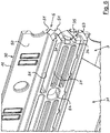
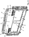
- Figure 11 shows one of the longer side walls 3 of another container 1 and a reinforcement profile 5 not yet connected to it, in a view obliquely from above.
- the reinforcement profile 5 can be latched to the rest of the side wall by being plugged in from top to bottom, for which purpose the side wall 3 has latching elements 34 and the reinforcement profile 5 has latching elements 54 cooperating therewith.
- the reinforcement profile 5 here has a downward-facing guide pin 57, each of which is close to the corresponding receptacle Side edges of the side wall 3 are receivable.
- the guide pins 57 in particular prevent the reinforcement profile 5 from tilting, which here again has an upwardly pointing profile web 50 with the top-side slide track 11, on which the weight of the respective upper container when stacking containers 1 is loaded when it is moved into the congruent stacking position.
- Figure 12 shows the side wall 3 Figure 11 with associated reinforcement profile 5, also in an oblique view from above.
- the locking elements 34 of the side wall 3 and the locking elements 54 of the reinforcement profile 5 are now in locking engagement with one another and secure the reinforcement profile 5 in its assembly position on the side wall 3.
- the reinforcement profile 5 projects upwards from its longitudinally extending profile web 50, the upper side of which is the slideway 11 forms with their bevelled end regions 12.
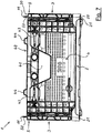
- Figure 13 finally shows one of the longer side walls 3 of a further container 1 and a reinforcing profile 5 connected to it, in a view obliquely from above. It is characteristic of the exemplary embodiment shown here that the reinforcement profile 5 is welded to the remaining side wall 3 or that the side wall 3 including the reinforcement profile 5 is produced as a two-component injection molded part. In both versions, which do not differ in their appearance from the outside, the reinforcement profile 5 is particularly firmly and permanently securely connected to the remaining side wall 3.
- the slideway 11 is formed on the upper side of a web 35 of the stack contour 30 of the side wall 3, that is to say not part of the reinforcing profile 5 in this exemplary embodiment.
- Slideway 12th End ranges from 11 2nd Floor of 1 20 Stack contour on 2 21 Grooves in 20 3rd first, longer side walls 30th Stack contour on 3 31 Handle opening in 3 32 Hinges on 3 33 flexible wall area of 3 34 Locking elements on 3 35 Footbridge at the top of 3 4th second, shorter side walls 40 Stack contour / upper edge on 4 41 Handle opening in 4 43 Locking means 44 Hump at 4 5 Reinforcement profiles 50 Profile web on top of 5 51 Profile wing on the side of 5 53 Groove down in 5 for 35 54 Snap elements on 5 55 Longitudinal webs 56 Crossbars 57 Guide pin
Landscapes
- Engineering & Computer Science (AREA)
- Mechanical Engineering (AREA)
- Ceramic Engineering (AREA)
- Stackable Containers (AREA)
- Rigid Containers With Two Or More Constituent Elements (AREA)
- Devices For Use In Laboratory Experiments (AREA)
- Table Devices Or Equipment (AREA)
Claims (8)
- Récipient (1) en matière plastique, comprenant un fond (2) rectangulaire et quatre parois latérales (3, 4), le fond (2) présentant, sur sa face inférieure et sur son bord extérieur, un premier contour d'empilage (20), les parois latérales (3, 4) présentant, dans leur zone de bord supérieure, un deuxième contour d'empilage (30, 40), sachant que lors de l'empilage de récipients (1) les uns sur les autres, le premier contour d'empilage (20) d'un récipient (1) supérieur et le deuxième contour d'empilage (30, 40) d'un récipient (1) inférieur entrent en prise l'un avec l'autre, avec un effet de centrage, le récipient étant un récipient (1) pliable dont les parois latérales (3, 4) sont articulées avec le fond (2), le fond (2) présentant des rainures (21) qui sont ouvertes vers le bas, caractérisé en ce que la zone de bord supérieure d'au moins deux parois latérales (3, 4) se faisant face est renforcée par au moins un profil de renforcement (5) monté par forme et/ou par adhérence sur le reste de la paroi latérale (3, 4), le profil de renforcement (5) n'étant pas constitué du même matériau que le reste de la paroi latérale (3, 4), et en ce que le/chaque profil de renforcement (5) présente, sur sa face supérieure éloignée du récipient (1), au moins une nervure profilée (50) qui s'étend dans le sens longitudinal du profil de renforcement (5) et forme une glissière (11) pour un autre récipient (1) devant être posé dessus, les rainures (21) étant disposées de manière à coïncider avec les nervures profilées (50), où au moins un des profils de renforcement peut être verrouillé avec le reste de la paroi latérale (3, 4) par insertion de haut en bas, la paroi latérale (3, 4) présentant à cet effet des éléments d'encliquetage (34), et le profil de renforcement (5) présentant des éléments d'encliquetage (54) coopérant avec ceux-ci, le profil de renforcement comportant, à ses extrémités frontales, respectivement un doigt de guidage (57) qui est tourné vers le bas et peut être engagé dans un logement respectif situé à proximité des bords latéraux de la paroi latérale (3, 4).
- Récipient (1) selon la revendication 1, caractérisé en ce que le/chaque profil de renforcement (5), dans une région inférieure tournée vers la paroi latérale (3, 4), présente une rainure (53) ouverte vers le bas ou une nervure tournée vers le bas, en ce que, sur le bord supérieur du reste de la paroi latérale (3, 4), il est prévu une nervure (35) tournée vers le haut ou une rainure ouverte vers le haut, et en ce que le profil de renforcement (5) est encliqueté ou serré ou glissé avec sa rainure (53) sur la nervure (35) de la paroi latérale (3, 4) ou est encliqueté ou serré ou glissé avec sa nervure dans la rainure de la paroi latérale (3, 4).
- Récipient (1) selon l'une des revendications précédentes, caractérisé en ce que les éléments d'encliquetage (34, 54) qui coopèrent sont formés sur la paroi latérale (3, 4) et sur le profil de renforcement (5) associé.
- Récipient (1) selon l'une des revendications précédentes, caractérisé en ce que la zone de bord supérieure de deux parois latérales (3) plus longues se faisant face est renforcée respectivement par un profil de renforcement (5) qui s'étend en continu sur la longueur de la paroi latérale (3) associée.
- Récipient (1) selon l'une des revendications précédentes, caractérisé en ce que les parois latérales (3, 4) elles-mêmes sont constituées d'une matière plastique thermoplastique non renforcée, et en ce que le/chaque profil de renforcement (5) est constitué d'une matière plastique renforcée par fibres ou de métal.
- Récipient (1) selon l'une des revendications précédentes, caractérisé en ce que des portions du contour d'empilage (20) du fond (2) qui se situent au-dessous des parois latérales (3, 4) présentant les glissières (11) sont réalisées respectivement avec l'une des rainures (21), en ce que les glissières (11) et les rainures (21) sont réalisées respectivement de telle sorte que lorsqu'un récipient (1) supérieur est posé sur un récipient (1) inférieur, dans une position de décalage réciproque dans le sens longitudinal des glissières (11) et des rainures (21), le récipient (1) supérieur repose dans une position surélevée sur les glissières (11) du récipient (1) inférieur, de manière à pouvoir être déplacé, et en ce que lors d'un déplacement ou après un déplacement du récipient (1) supérieur, jusqu'à une position où il coïncide avec le récipient (1) inférieur, les glissières (11) s'engagent dans les rainures (21) par abaissement du récipient (1) supérieur, occupant ainsi une position d'empilage finale.
- Récipient (1) selon la revendication 6, caractérisé en ce que les glissière (11) sont conçues chacune comme une nappe alignée verticalement, continue ou interrompue et chaque glissière (11) est réalisée sous une forme étagée ou inclinée ou arrondie dans ses zones d'extrémité (12).
- Récipient (1) selon l'une des revendications précédentes, caractérisé en ce que les deux parois latérales (3 ou 4) qui ne sont pas dotées des glissières (11) présentent, sur leur face supérieure, respectivement un ou plusieurs bossages (44) qui sont espacés les uns des autres dans le sens longitudinal de ces parois latérales (3 ou 4), qui bloquent un récipient classique posé sur le récipient (1) pour l'empêcher de se déplacer dans le sens longitudinal des glissières (11), et dont la hauteur correspond à la hauteur des glissières (11).
Priority Applications (2)
| Application Number | Priority Date | Filing Date | Title |
|---|---|---|---|
| DK20154707.2T DK3712084T3 (da) | 2015-11-17 | 2016-11-17 | Beholder af kunststof |
| EP20154707.2A EP3712084B1 (fr) | 2015-11-17 | 2016-11-17 | Récipient en matière plastique |
Applications Claiming Priority (2)
| Application Number | Priority Date | Filing Date | Title |
|---|---|---|---|
| DE202015106211.7U DE202015106211U1 (de) | 2015-11-17 | 2015-11-17 | Behälter aus Kunststoff |
| PCT/EP2016/077965 WO2017085171A1 (fr) | 2015-11-17 | 2016-11-17 | Réceptacle en matière plastique |
Related Child Applications (2)
| Application Number | Title | Priority Date | Filing Date |
|---|---|---|---|
| EP20154707.2A Division-Into EP3712084B1 (fr) | 2015-11-17 | 2016-11-17 | Récipient en matière plastique |
| EP20154707.2A Division EP3712084B1 (fr) | 2015-11-17 | 2016-11-17 | Récipient en matière plastique |
Publications (2)
| Publication Number | Publication Date |
|---|---|
| EP3377416A1 EP3377416A1 (fr) | 2018-09-26 |
| EP3377416B1 true EP3377416B1 (fr) | 2020-07-15 |
Family
ID=57530638
Family Applications (2)
| Application Number | Title | Priority Date | Filing Date |
|---|---|---|---|
| EP16808925.8A Active EP3377416B1 (fr) | 2015-11-17 | 2016-11-17 | Réceptacle en matière plastique |
| EP20154707.2A Active EP3712084B1 (fr) | 2015-11-17 | 2016-11-17 | Récipient en matière plastique |
Family Applications After (1)
| Application Number | Title | Priority Date | Filing Date |
|---|---|---|---|
| EP20154707.2A Active EP3712084B1 (fr) | 2015-11-17 | 2016-11-17 | Récipient en matière plastique |
Country Status (12)
| Country | Link |
|---|---|
| US (1) | US11180282B2 (fr) |
| EP (2) | EP3377416B1 (fr) |
| AU (1) | AU2016355962B2 (fr) |
| DE (1) | DE202015106211U1 (fr) |
| DK (2) | DK3377416T3 (fr) |
| ES (2) | ES2825327T3 (fr) |
| FI (1) | FI3712084T3 (fr) |
| MA (1) | MA52985A (fr) |
| PL (1) | PL3712084T3 (fr) |
| PT (2) | PT3377416T (fr) |
| RU (1) | RU2717771C2 (fr) |
| WO (1) | WO2017085171A1 (fr) |
Families Citing this family (4)
| Publication number | Priority date | Publication date | Assignee | Title |
|---|---|---|---|---|
| CN113874273A (zh) * | 2019-04-03 | 2021-12-31 | Knap公司 | 用于对容器进行支撑和称重的推车 |
| CH717725A1 (de) * | 2020-08-10 | 2022-02-15 | Utz Georg Holding Ag | Kunststoffbehälter. |
| EP4059860B1 (fr) * | 2021-03-17 | 2023-09-13 | Euro Pool System International B.v. | Conteneur empilable pourvu de parois rabattables |
| USD1068274S1 (en) * | 2022-11-18 | 2025-04-01 | Monoflo International, Inc. | Container with drain openings |
Family Cites Families (22)
| Publication number | Priority date | Publication date | Assignee | Title |
|---|---|---|---|---|
| CH361240A (de) | 1958-07-23 | 1962-03-31 | Walther Dipl Ing Zarges | Stapelbarer Behälter |
| DE1825467U (de) | 1960-11-21 | 1961-01-19 | Bayha & Strackbein G M B H | Stapelbarer transportkasten. |
| US3675815A (en) * | 1970-12-16 | 1972-07-11 | Houston Rehrig | Bakery tray |
| DE7910849U1 (de) | 1979-04-12 | 1979-08-30 | Schoeller & Co Ag A | Einstueckig geformter thermoplastischer Kunststoffkasten |
| NL8802952A (nl) | 1988-11-30 | 1990-06-18 | Dynoplast Bv | Stapelbare bak. |
| DE9005131U1 (de) | 1990-05-07 | 1990-09-06 | Ringoplast GmbH, 4459 Ringe | Vorrichtung aus Kunststoff zum Transport von Backgut |
| US5145082A (en) * | 1991-09-10 | 1992-09-08 | Craft Jr Charles W | Handle reinforcement mechanism for laundry basket |
| US5295632B1 (en) * | 1992-12-18 | 1998-04-21 | Bradford Co | Tote box with self locking top rail |
| DE59507654D1 (de) * | 1995-10-26 | 2000-02-24 | Wilhelm Goetz | Kasten, insbesondere Flaschenkasten und Verfahren zum Herstellen eines solchen Kastens |
| DE29601187U1 (de) | 1996-01-25 | 1996-03-28 | FEBRA-Kunststoffe GmbH & Co., 74336 Brackenheim | Ladungsträger mit versteiftem Stapelrand |
| DE29710185U1 (de) | 1997-06-11 | 1997-08-14 | Gebrüder Ruch GmbH & Co KG, 77704 Oberkirch | Stapelbare Verpackung |
| DE19730063A1 (de) | 1997-07-14 | 1999-01-21 | Fischer Johannes | Stapelbarer Transportbehälter |
| DE29902158U1 (de) | 1999-02-06 | 1999-05-12 | Kunststoffwerk Katzbach GmbH, 93413 Cham | Geschäumter Transportbehälter mit Versteifungsprofilen |
| DE29904563U1 (de) | 1999-03-12 | 1999-06-10 | Ruch Novaplast GmbH + Co. KG., 77704 Oberkirch | Stapelbare Verpackung |
| DE20006094U1 (de) | 2000-04-01 | 2000-09-14 | Jokey Plastik Gummersbach GmbH, 51645 Gummersbach | Kunststoffbehälter mit einrastbarem Deckel |
| DE20114888U1 (de) * | 2001-08-16 | 2002-12-19 | KR-Porsiplast Verpackungssysteme GmbH, 76461 Muggensturm | Verpackungsbehälter mit verrasteter Behälterwand |
| DE10160969B4 (de) | 2001-12-11 | 2005-11-03 | Tecno-Plast Kunststoffwerk Ges.M.B.H. | Schachtelartiger Behälter |
| DE102009049186A1 (de) * | 2009-04-15 | 2010-11-04 | Ifco Systems Gmbh | Kiste mit faltbaren und selbstarretierenden Seitenwänden |
| ATE556947T1 (de) * | 2009-08-14 | 2012-05-15 | Rehrig Pacific Co | Bäckereibehälter und rollwagen |
| EP2371726A1 (fr) * | 2010-03-30 | 2011-10-05 | IFCO Systems GmbH | Caisse |
| GR20130100519A (el) * | 2013-09-17 | 2015-04-21 | Ηλιας Μιλτιαδη Τσαμουργκελης | Κιβωτιο πολλαπλων χρησεων |
| DE202014101556U1 (de) | 2014-04-02 | 2014-07-08 | Bekuplast Gmbh | Behälter für den Transport und die Lagerung von Gütern |
-
2015
- 2015-11-17 DE DE202015106211.7U patent/DE202015106211U1/de not_active Expired - Lifetime
-
2016
- 2016-11-17 PL PL20154707.2T patent/PL3712084T3/pl unknown
- 2016-11-17 DK DK16808925.8T patent/DK3377416T3/da active
- 2016-11-17 ES ES16808925T patent/ES2825327T3/es active Active
- 2016-11-17 US US15/776,431 patent/US11180282B2/en active Active
- 2016-11-17 RU RU2018121533A patent/RU2717771C2/ru active
- 2016-11-17 FI FIEP20154707.2T patent/FI3712084T3/fi active
- 2016-11-17 WO PCT/EP2016/077965 patent/WO2017085171A1/fr not_active Ceased
- 2016-11-17 PT PT168089258T patent/PT3377416T/pt unknown
- 2016-11-17 AU AU2016355962A patent/AU2016355962B2/en active Active
- 2016-11-17 MA MA052985A patent/MA52985A/fr unknown
- 2016-11-17 EP EP16808925.8A patent/EP3377416B1/fr active Active
- 2016-11-17 ES ES20154707T patent/ES2946289T3/es active Active
- 2016-11-17 DK DK20154707.2T patent/DK3712084T3/da active
- 2016-11-17 EP EP20154707.2A patent/EP3712084B1/fr active Active
- 2016-11-17 PT PT201547072T patent/PT3712084T/pt unknown
Non-Patent Citations (1)
| Title |
|---|
| None * |
Also Published As
| Publication number | Publication date |
|---|---|
| DK3377416T3 (da) | 2020-10-19 |
| AU2016355962A1 (en) | 2018-07-05 |
| FI3712084T3 (fi) | 2023-05-16 |
| EP3712084B1 (fr) | 2023-02-15 |
| US11180282B2 (en) | 2021-11-23 |
| US20190031392A1 (en) | 2019-01-31 |
| EP3712084A1 (fr) | 2020-09-23 |
| MA52985A (fr) | 2021-04-28 |
| PT3377416T (pt) | 2020-10-21 |
| PT3712084T (pt) | 2023-05-22 |
| ES2946289T3 (es) | 2023-07-14 |
| DK3712084T3 (da) | 2023-05-22 |
| RU2018121533A3 (fr) | 2020-01-29 |
| WO2017085171A1 (fr) | 2017-05-26 |
| PL3712084T3 (pl) | 2023-10-02 |
| RU2717771C2 (ru) | 2020-03-25 |
| ES2825327T3 (es) | 2021-05-17 |
| NZ743535A (en) | 2021-10-29 |
| RU2018121533A (ru) | 2019-12-18 |
| AU2016355962B2 (en) | 2021-10-07 |
| EP3377416A1 (fr) | 2018-09-26 |
| DE202015106211U1 (de) | 2017-02-20 |
Similar Documents
| Publication | Publication Date | Title |
|---|---|---|
| EP2878548B1 (fr) | Palette | |
| DE69432688T3 (de) | Stapelbarer Behälter | |
| DE2000543A1 (de) | Verpackungsbehaeltnis | |
| EP2036838A1 (fr) | Agencement de couvercle pour un récipient à liquide | |
| EP3377416B1 (fr) | Réceptacle en matière plastique | |
| DE102018106981A1 (de) | Behältersystem mit Rahmenelement | |
| DE1286443B (de) | Stapelbarer und schachtelbarer Behaelter | |
| EP1428764A1 (fr) | Conteneur empilable | |
| DE202014101556U1 (de) | Behälter für den Transport und die Lagerung von Gütern | |
| DE102007033147B4 (de) | Stapelbarer Rollbehälter | |
| DE102007020277A1 (de) | Mehrteilige Palette | |
| EP2918508A1 (fr) | Récipient, en particulier récipient pour palettes | |
| EP2767483B1 (fr) | Récipient de transport empilable | |
| EP3753857B1 (fr) | Élément de paroi d'un cadre de rehausse de palette et cadre de rehausse de palette | |
| DE102012006321B4 (de) | Teilbarer Behälter, insbesondere Flaschenkasten | |
| DE2155627A1 (de) | Transportpalette | |
| DE202004014340U1 (de) | Drehstapelbehälter | |
| EP2338799B1 (fr) | Récipient en matière synthétique thermoplastique | |
| EP2987742B1 (fr) | Recipient empilable ayant une structure de transfert de charge | |
| EP3034425A1 (fr) | Recipient emboitable dote de parois laterales basculantes | |
| DE2112190A1 (de) | Zusammenlegbarer Kasten aus Kunststoff | |
| EP1319603B1 (fr) | Récipient en forme de boîte | |
| EP2539655B1 (fr) | Refrigerateur avec récipient amovible | |
| WO2016131523A1 (fr) | Caisse en plastique, notamment caisse à bouteilles | |
| DE2819677C3 (de) | Kasten aus Kunststoff, insbesondere für den Transport von Obst und Gemüse |
Legal Events
| Date | Code | Title | Description |
|---|---|---|---|
| STAA | Information on the status of an ep patent application or granted ep patent |
Free format text: STATUS: UNKNOWN |
|
| STAA | Information on the status of an ep patent application or granted ep patent |
Free format text: STATUS: THE INTERNATIONAL PUBLICATION HAS BEEN MADE |
|
| PUAI | Public reference made under article 153(3) epc to a published international application that has entered the european phase |
Free format text: ORIGINAL CODE: 0009012 |
|
| STAA | Information on the status of an ep patent application or granted ep patent |
Free format text: STATUS: REQUEST FOR EXAMINATION WAS MADE |
|
| 17P | Request for examination filed |
Effective date: 20180613 |
|
| AK | Designated contracting states |
Kind code of ref document: A1 Designated state(s): AL AT BE BG CH CY CZ DE DK EE ES FI FR GB GR HR HU IE IS IT LI LT LU LV MC MK MT NL NO PL PT RO RS SE SI SK SM TR |
|
| AX | Request for extension of the european patent |
Extension state: BA ME |
|
| GRAP | Despatch of communication of intention to grant a patent |
Free format text: ORIGINAL CODE: EPIDOSNIGR1 |
|
| STAA | Information on the status of an ep patent application or granted ep patent |
Free format text: STATUS: GRANT OF PATENT IS INTENDED |
|
| INTG | Intention to grant announced |
Effective date: 20190920 |
|
| GRAS | Grant fee paid |
Free format text: ORIGINAL CODE: EPIDOSNIGR3 |
|
| GRAJ | Information related to disapproval of communication of intention to grant by the applicant or resumption of examination proceedings by the epo deleted |
Free format text: ORIGINAL CODE: EPIDOSDIGR1 |
|
| GRAL | Information related to payment of fee for publishing/printing deleted |
Free format text: ORIGINAL CODE: EPIDOSDIGR3 |
|
| STAA | Information on the status of an ep patent application or granted ep patent |
Free format text: STATUS: REQUEST FOR EXAMINATION WAS MADE |
|
| GRAP | Despatch of communication of intention to grant a patent |
Free format text: ORIGINAL CODE: EPIDOSNIGR1 |
|
| STAA | Information on the status of an ep patent application or granted ep patent |
Free format text: STATUS: GRANT OF PATENT IS INTENDED |
|
| INTC | Intention to grant announced (deleted) | ||
| INTG | Intention to grant announced |
Effective date: 20200226 |
|
| GRAA | (expected) grant |
Free format text: ORIGINAL CODE: 0009210 |
|
| STAA | Information on the status of an ep patent application or granted ep patent |
Free format text: STATUS: THE PATENT HAS BEEN GRANTED |
|
| AK | Designated contracting states |
Kind code of ref document: B1 Designated state(s): AL AT BE BG CH CY CZ DE DK EE ES FI FR GB GR HR HU IE IS IT LI LT LU LV MC MK MT NL NO PL PT RO RS SE SI SK SM TR |
|
| AX | Request for extension of the european patent |
Extension state: BA ME |
|
| REG | Reference to a national code |
Ref country code: CH Ref legal event code: EP Ref country code: GB Ref legal event code: FG4D Free format text: NOT ENGLISH |
|
| REG | Reference to a national code |
Ref country code: IE Ref legal event code: FG4D Free format text: LANGUAGE OF EP DOCUMENT: GERMAN |
|
| REG | Reference to a national code |
Ref country code: DE Ref legal event code: R096 Ref document number: 502016010548 Country of ref document: DE |
|
| REG | Reference to a national code |
Ref country code: AT Ref legal event code: REF Ref document number: 1290803 Country of ref document: AT Kind code of ref document: T Effective date: 20200815 |
|
| REG | Reference to a national code |
Ref country code: FI Ref legal event code: FGE |
|
| REG | Reference to a national code |
Ref country code: DK Ref legal event code: T3 Effective date: 20201013 |
|
| REG | Reference to a national code |
Ref country code: PT Ref legal event code: SC4A Ref document number: 3377416 Country of ref document: PT Date of ref document: 20201021 Kind code of ref document: T Free format text: AVAILABILITY OF NATIONAL TRANSLATION Effective date: 20201014 |
|
| REG | Reference to a national code |
Ref country code: NL Ref legal event code: FP |
|
| REG | Reference to a national code |
Ref country code: LT Ref legal event code: MG4D |
|
| REG | Reference to a national code |
Ref country code: NO Ref legal event code: T2 Effective date: 20200715 |
|
| PG25 | Lapsed in a contracting state [announced via postgrant information from national office to epo] |
Ref country code: GR Free format text: LAPSE BECAUSE OF FAILURE TO SUBMIT A TRANSLATION OF THE DESCRIPTION OR TO PAY THE FEE WITHIN THE PRESCRIBED TIME-LIMIT Effective date: 20201016 Ref country code: HR Free format text: LAPSE BECAUSE OF FAILURE TO SUBMIT A TRANSLATION OF THE DESCRIPTION OR TO PAY THE FEE WITHIN THE PRESCRIBED TIME-LIMIT Effective date: 20200715 Ref country code: SE Free format text: LAPSE BECAUSE OF FAILURE TO SUBMIT A TRANSLATION OF THE DESCRIPTION OR TO PAY THE FEE WITHIN THE PRESCRIBED TIME-LIMIT Effective date: 20200715 Ref country code: LT Free format text: LAPSE BECAUSE OF FAILURE TO SUBMIT A TRANSLATION OF THE DESCRIPTION OR TO PAY THE FEE WITHIN THE PRESCRIBED TIME-LIMIT Effective date: 20200715 Ref country code: BG Free format text: LAPSE BECAUSE OF FAILURE TO SUBMIT A TRANSLATION OF THE DESCRIPTION OR TO PAY THE FEE WITHIN THE PRESCRIBED TIME-LIMIT Effective date: 20201015 |
|
| PG25 | Lapsed in a contracting state [announced via postgrant information from national office to epo] |
Ref country code: RS Free format text: LAPSE BECAUSE OF FAILURE TO SUBMIT A TRANSLATION OF THE DESCRIPTION OR TO PAY THE FEE WITHIN THE PRESCRIBED TIME-LIMIT Effective date: 20200715 Ref country code: LV Free format text: LAPSE BECAUSE OF FAILURE TO SUBMIT A TRANSLATION OF THE DESCRIPTION OR TO PAY THE FEE WITHIN THE PRESCRIBED TIME-LIMIT Effective date: 20200715 Ref country code: IS Free format text: LAPSE BECAUSE OF FAILURE TO SUBMIT A TRANSLATION OF THE DESCRIPTION OR TO PAY THE FEE WITHIN THE PRESCRIBED TIME-LIMIT Effective date: 20201115 |
|
| REG | Reference to a national code |
Ref country code: DE Ref legal event code: R097 Ref document number: 502016010548 Country of ref document: DE |
|
| PG25 | Lapsed in a contracting state [announced via postgrant information from national office to epo] |
Ref country code: EE Free format text: LAPSE BECAUSE OF FAILURE TO SUBMIT A TRANSLATION OF THE DESCRIPTION OR TO PAY THE FEE WITHIN THE PRESCRIBED TIME-LIMIT Effective date: 20200715 Ref country code: SM Free format text: LAPSE BECAUSE OF FAILURE TO SUBMIT A TRANSLATION OF THE DESCRIPTION OR TO PAY THE FEE WITHIN THE PRESCRIBED TIME-LIMIT Effective date: 20200715 Ref country code: RO Free format text: LAPSE BECAUSE OF FAILURE TO SUBMIT A TRANSLATION OF THE DESCRIPTION OR TO PAY THE FEE WITHIN THE PRESCRIBED TIME-LIMIT Effective date: 20200715 |
|
| REG | Reference to a national code |
Ref country code: ES Ref legal event code: FG2A Ref document number: 2825327 Country of ref document: ES Kind code of ref document: T3 Effective date: 20210517 |
|
| PLBE | No opposition filed within time limit |
Free format text: ORIGINAL CODE: 0009261 |
|
| STAA | Information on the status of an ep patent application or granted ep patent |
Free format text: STATUS: NO OPPOSITION FILED WITHIN TIME LIMIT |
|
| PG25 | Lapsed in a contracting state [announced via postgrant information from national office to epo] |
Ref country code: AL Free format text: LAPSE BECAUSE OF FAILURE TO SUBMIT A TRANSLATION OF THE DESCRIPTION OR TO PAY THE FEE WITHIN THE PRESCRIBED TIME-LIMIT Effective date: 20200715 |
|
| VS25 | Lapsed in a validation state [announced via postgrant information from nat. office to epo] |
Ref country code: MD Free format text: LAPSE BECAUSE OF FAILURE TO SUBMIT A TRANSLATION OF THE DESCRIPTION OR TO PAY THE FEE WITHIN THE PRESCRIBED TIME-LIMIT Effective date: 20200715 Ref country code: MA Free format text: LAPSE BECAUSE OF FAILURE TO SUBMIT A TRANSLATION OF THE DESCRIPTION OR TO PAY THE FEE WITHIN THE PRESCRIBED TIME-LIMIT Effective date: 20200715 |
|
| 26N | No opposition filed |
Effective date: 20210416 |
|
| PG25 | Lapsed in a contracting state [announced via postgrant information from national office to epo] |
Ref country code: SK Free format text: LAPSE BECAUSE OF FAILURE TO SUBMIT A TRANSLATION OF THE DESCRIPTION OR TO PAY THE FEE WITHIN THE PRESCRIBED TIME-LIMIT Effective date: 20200715 Ref country code: MC Free format text: LAPSE BECAUSE OF FAILURE TO SUBMIT A TRANSLATION OF THE DESCRIPTION OR TO PAY THE FEE WITHIN THE PRESCRIBED TIME-LIMIT Effective date: 20200715 |
|
| REG | Reference to a national code |
Ref country code: CH Ref legal event code: PL |
|
| PG25 | Lapsed in a contracting state [announced via postgrant information from national office to epo] |
Ref country code: LU Free format text: LAPSE BECAUSE OF NON-PAYMENT OF DUE FEES Effective date: 20201117 |
|
| PG25 | Lapsed in a contracting state [announced via postgrant information from national office to epo] |
Ref country code: CH Free format text: LAPSE BECAUSE OF NON-PAYMENT OF DUE FEES Effective date: 20201130 Ref country code: LI Free format text: LAPSE BECAUSE OF NON-PAYMENT OF DUE FEES Effective date: 20201130 Ref country code: SI Free format text: LAPSE BECAUSE OF FAILURE TO SUBMIT A TRANSLATION OF THE DESCRIPTION OR TO PAY THE FEE WITHIN THE PRESCRIBED TIME-LIMIT Effective date: 20200715 |
|
| PG25 | Lapsed in a contracting state [announced via postgrant information from national office to epo] |
Ref country code: TR Free format text: LAPSE BECAUSE OF FAILURE TO SUBMIT A TRANSLATION OF THE DESCRIPTION OR TO PAY THE FEE WITHIN THE PRESCRIBED TIME-LIMIT Effective date: 20200715 Ref country code: MT Free format text: LAPSE BECAUSE OF FAILURE TO SUBMIT A TRANSLATION OF THE DESCRIPTION OR TO PAY THE FEE WITHIN THE PRESCRIBED TIME-LIMIT Effective date: 20200715 Ref country code: CY Free format text: LAPSE BECAUSE OF FAILURE TO SUBMIT A TRANSLATION OF THE DESCRIPTION OR TO PAY THE FEE WITHIN THE PRESCRIBED TIME-LIMIT Effective date: 20200715 |
|
| PG25 | Lapsed in a contracting state [announced via postgrant information from national office to epo] |
Ref country code: MK Free format text: LAPSE BECAUSE OF FAILURE TO SUBMIT A TRANSLATION OF THE DESCRIPTION OR TO PAY THE FEE WITHIN THE PRESCRIBED TIME-LIMIT Effective date: 20200715 |
|
| P01 | Opt-out of the competence of the unified patent court (upc) registered |
Effective date: 20230612 |
|
| PGFP | Annual fee paid to national office [announced via postgrant information from national office to epo] |
Ref country code: PT Payment date: 20251103 Year of fee payment: 10 |
|
| PGFP | Annual fee paid to national office [announced via postgrant information from national office to epo] |
Ref country code: NL Payment date: 20251119 Year of fee payment: 10 |
|
| PGFP | Annual fee paid to national office [announced via postgrant information from national office to epo] |
Ref country code: DE Payment date: 20251118 Year of fee payment: 10 |
|
| PGFP | Annual fee paid to national office [announced via postgrant information from national office to epo] |
Ref country code: GB Payment date: 20251125 Year of fee payment: 10 |
|
| PGFP | Annual fee paid to national office [announced via postgrant information from national office to epo] |
Ref country code: NO Payment date: 20251118 Year of fee payment: 10 |
|
| PGFP | Annual fee paid to national office [announced via postgrant information from national office to epo] |
Ref country code: AT Payment date: 20251117 Year of fee payment: 10 |
|
| PGFP | Annual fee paid to national office [announced via postgrant information from national office to epo] |
Ref country code: IT Payment date: 20251128 Year of fee payment: 10 Ref country code: FI Payment date: 20251118 Year of fee payment: 10 Ref country code: DK Payment date: 20251119 Year of fee payment: 10 |
|
| PGFP | Annual fee paid to national office [announced via postgrant information from national office to epo] |
Ref country code: FR Payment date: 20251118 Year of fee payment: 10 |
|
| PGFP | Annual fee paid to national office [announced via postgrant information from national office to epo] |
Ref country code: BE Payment date: 20251119 Year of fee payment: 10 |
|
| PGFP | Annual fee paid to national office [announced via postgrant information from national office to epo] |
Ref country code: IE Payment date: 20251120 Year of fee payment: 10 Ref country code: CZ Payment date: 20251104 Year of fee payment: 10 |
|
| PGFP | Annual fee paid to national office [announced via postgrant information from national office to epo] |
Ref country code: PL Payment date: 20251106 Year of fee payment: 10 |
|
| PGFP | Annual fee paid to national office [announced via postgrant information from national office to epo] |
Ref country code: ES Payment date: 20251216 Year of fee payment: 10 |