EP3377417B1 - Dosendeckel - Google Patents
Dosendeckel Download PDFInfo
- Publication number
- EP3377417B1 EP3377417B1 EP16794325.7A EP16794325A EP3377417B1 EP 3377417 B1 EP3377417 B1 EP 3377417B1 EP 16794325 A EP16794325 A EP 16794325A EP 3377417 B1 EP3377417 B1 EP 3377417B1
- Authority
- EP
- European Patent Office
- Prior art keywords
- lid
- tab
- accordance
- opening
- tongue tab
- Prior art date
- Legal status (The legal status is an assumption and is not a legal conclusion. Google has not performed a legal analysis and makes no representation as to the accuracy of the status listed.)
- Active
Links
Images
Classifications
-
- B—PERFORMING OPERATIONS; TRANSPORTING
- B65—CONVEYING; PACKING; STORING; HANDLING THIN OR FILAMENTARY MATERIAL
- B65D—CONTAINERS FOR STORAGE OR TRANSPORT OF ARTICLES OR MATERIALS, e.g. BAGS, BARRELS, BOTTLES, BOXES, CANS, CARTONS, CRATES, DRUMS, JARS, TANKS, HOPPERS, FORWARDING CONTAINERS; ACCESSORIES, CLOSURES, OR FITTINGS THEREFOR; PACKAGING ELEMENTS; PACKAGES
- B65D17/00—Rigid or semi-rigid containers specially constructed to be opened by cutting or piercing, or by tearing of frangible members or portions
- B65D17/28—Rigid or semi-rigid containers specially constructed to be opened by cutting or piercing, or by tearing of frangible members or portions at lines or points of weakness
- B65D17/401—Rigid or semi-rigid containers specially constructed to be opened by cutting or piercing, or by tearing of frangible members or portions at lines or points of weakness characterised by having the line of weakness provided in an end wall
- B65D17/4012—Rigid or semi-rigid containers specially constructed to be opened by cutting or piercing, or by tearing of frangible members or portions at lines or points of weakness characterised by having the line of weakness provided in an end wall for opening partially by means of a tearing tab
-
- B—PERFORMING OPERATIONS; TRANSPORTING
- B65—CONVEYING; PACKING; STORING; HANDLING THIN OR FILAMENTARY MATERIAL
- B65D—CONTAINERS FOR STORAGE OR TRANSPORT OF ARTICLES OR MATERIALS, e.g. BAGS, BARRELS, BOTTLES, BOXES, CANS, CARTONS, CRATES, DRUMS, JARS, TANKS, HOPPERS, FORWARDING CONTAINERS; ACCESSORIES, CLOSURES, OR FITTINGS THEREFOR; PACKAGING ELEMENTS; PACKAGES
- B65D17/00—Rigid or semi-rigid containers specially constructed to be opened by cutting or piercing, or by tearing of frangible members or portions
- B65D17/28—Rigid or semi-rigid containers specially constructed to be opened by cutting or piercing, or by tearing of frangible members or portions at lines or points of weakness
- B65D17/404—Details of the lines of weakness
-
- B—PERFORMING OPERATIONS; TRANSPORTING
- B65—CONVEYING; PACKING; STORING; HANDLING THIN OR FILAMENTARY MATERIAL
- B65D—CONTAINERS FOR STORAGE OR TRANSPORT OF ARTICLES OR MATERIALS, e.g. BAGS, BARRELS, BOTTLES, BOXES, CANS, CARTONS, CRATES, DRUMS, JARS, TANKS, HOPPERS, FORWARDING CONTAINERS; ACCESSORIES, CLOSURES, OR FITTINGS THEREFOR; PACKAGING ELEMENTS; PACKAGES
- B65D25/00—Details of other kinds or types of rigid or semi-rigid containers
- B65D25/14—Linings or internal coatings
-
- B—PERFORMING OPERATIONS; TRANSPORTING
- B65—CONVEYING; PACKING; STORING; HANDLING THIN OR FILAMENTARY MATERIAL
- B65D—CONTAINERS FOR STORAGE OR TRANSPORT OF ARTICLES OR MATERIALS, e.g. BAGS, BARRELS, BOTTLES, BOXES, CANS, CARTONS, CRATES, DRUMS, JARS, TANKS, HOPPERS, FORWARDING CONTAINERS; ACCESSORIES, CLOSURES, OR FITTINGS THEREFOR; PACKAGING ELEMENTS; PACKAGES
- B65D2517/00—Containers specially constructed to be opened by cutting, piercing or tearing of wall portions, e.g. preserving cans or tins
- B65D2517/0001—Details
- B65D2517/001—Action for opening container
- B65D2517/0014—Action for opening container pivot tab and push-down tear panel
-
- B—PERFORMING OPERATIONS; TRANSPORTING
- B65—CONVEYING; PACKING; STORING; HANDLING THIN OR FILAMENTARY MATERIAL
- B65D—CONTAINERS FOR STORAGE OR TRANSPORT OF ARTICLES OR MATERIALS, e.g. BAGS, BARRELS, BOTTLES, BOXES, CANS, CARTONS, CRATES, DRUMS, JARS, TANKS, HOPPERS, FORWARDING CONTAINERS; ACCESSORIES, CLOSURES, OR FITTINGS THEREFOR; PACKAGING ELEMENTS; PACKAGES
- B65D2517/00—Containers specially constructed to be opened by cutting, piercing or tearing of wall portions, e.g. preserving cans or tins
- B65D2517/0001—Details
- B65D2517/001—Action for opening container
- B65D2517/0016—Action for opening container pivot tab, push-down and pull-out tear panel
-
- B—PERFORMING OPERATIONS; TRANSPORTING
- B65—CONVEYING; PACKING; STORING; HANDLING THIN OR FILAMENTARY MATERIAL
- B65D—CONTAINERS FOR STORAGE OR TRANSPORT OF ARTICLES OR MATERIALS, e.g. BAGS, BARRELS, BOTTLES, BOXES, CANS, CARTONS, CRATES, DRUMS, JARS, TANKS, HOPPERS, FORWARDING CONTAINERS; ACCESSORIES, CLOSURES, OR FITTINGS THEREFOR; PACKAGING ELEMENTS; PACKAGES
- B65D2517/00—Containers specially constructed to be opened by cutting, piercing or tearing of wall portions, e.g. preserving cans or tins
- B65D2517/0001—Details
- B65D2517/0058—Other details of container end panel
- B65D2517/008—Materials of container end panel
- B65D2517/0082—Coated or laminated metal
Definitions
- the invention relates to a can lid, in particular for beverage cans, with a limited opening area provided in the metallic lid material of a lid surface, and with a two-armed lever element intended for opening this opening area, which is firmly connected to the lid material, in particular by riveting or welding.
- Can lids of this type are used on a very large scale worldwide. They are simple and inexpensive to manufacture and enable space-saving stacking of cans and opening of the cans by simply swinging up the long arm of the lever element.
- these generally known can lids have some serious disadvantages, which mainly consist in the fact that the lever part, which initially lies flat on the lid surface, is not easy to grasp, that when the lever member is swung up and the can is opened, the part of the lid that initially closes the opening area is pressed into the inside of the can and there comes into contact with the liquid, which is not hygienically perfect, and that during the opening process, ie when the existing weakening groove between the opening area and the lid surface is torn or severed, tiny aluminum particles are inevitably released from the lid material and also enter the can directly or via the lid portion pressed into the interior of the can. These tiny chips or aluminum particles are harmful to health if they get into the human body together with the drink.
- WO 2015/104659 discloses a can lid according to the preamble of claim 1.
- the object of the present invention is to create a can lid of the type mentioned at the outset without at least one of the disadvantages mentioned above, i.e. in particular a can lid, which is easier to open and easier to use than conventional can lids, is hygienically flawless and, above all, prevents the appearance of aluminum chips or aluminum microparticles during the opening process.
- a can provided with the lid according to the invention should correspond to the conventional cans with regard to the storage of the respective content, the manufacturing, transport and handling properties.
- this object is essentially achieved in that the opening area is designed as a tongue tab, which is separated from the lid surface by a micro-gap extending over the tab circumference, in particular a punching gap, and the tongue tab base connected to the lid surface
- the opening process becomes effective as an articulated bearing, and that the coating is weakened adjacent to the microgap between the tongue tab and the lid surface, in particular notched and preferably at least partially notched.
- microgap is preferably made by a punching process with subsequent return of the tongue flap pressed out of the can lid material by punching into its starting position before Get punching.
- the easy opening of the can ie possible with little force, is a consequence of the fact that it is not necessary to cut through metal and the film on the underside is only peeled off in a very narrow area due to the notch during opening.
- the two-armed lever member is attached to the lid surface and the short lever arm pivots the tongue tab during the opening process together with the partial area of the plastic coating covering it on the underside and delimited by the line of weakness into the interior of the can , this being made possible by the fact that the notch line is located outside the microgap.
- a preferred development of the basic principle according to the invention is that the two-armed lever member is attached to the tongue tab and can be supported with its short lever arm on the lid surface, in particular on a stiffening area of the lid surface, and that the long lever arm during the opening process together with the one that covers it on the underside , pivoted to the outside by the partial area of the plastic coating which is delimited within the microgap.
- This embodiment combines all of the achievable advantages of the invention since, compared to the conventional can lids, the opening process requires a significantly lower effort, the occurrence of aluminum chips or aluminum microparticles during the opening process is completely avoided and, moreover, an optimum is achieved in terms of hygiene. there an immersion of can lid parts into the can interior and thus into the liquid in the can is prevented.
- An advantageous embodiment of the invention for all design variants is characterized in that the tongue tab of the metallic can lid is separated from the lid surface surrounding it with the formation of interlocking projections and recesses by a cutting, in particular a punching process, and that the tongue tab and the one adjacent to it Cover surface on the projections and recesses are positively and non-positively connected to form the micro-gap, the tightness of the finished, unopened can lid is ensured by the internal plastic coating or film.
- the sealing ability against can internal pressure is improved by a concave tongue tab.
- the projections and the recesses are preferably coupled via undercuts.
- the longer arm of the two-armed lever member is formed by a grip tab, in particular an annular tab, and the two-armed lever member is connected to the tongue tab off-center, in particular at the edge.
- the invention also includes all the cans which are provided with a can lid according to the invention, which is preferably connected to the respective can via a respective flanged edge, the plastic film provided on the underside of the lid in particular performing the sealing function in the connection area between the can lid and the can and which purposefully positioned notch allows opening with little force.
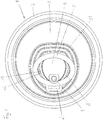
- Fig. 1 shows an embodiment of the can lid 1 according to the invention in a schematic plan view.
- this can lid is provided in a conventional manner with a flanged edge 2, the area lying within the flanged edge 2 being formed by a lid surface 3 which has an opening area 4 designed as a tongue tab offset with respect to the center.
- This metallic can lid which is made of aluminum material, is provided surrounding the opening area 4 with a stiffening area 14 formed by material deformation.
- a two-armed lever 5, 6 is connected to the opening area 4 or the tongue tab of the can lid, in particular riveted or welded, so that there is a fixed connection point 7.
- This connection point 7 lies in the edge region of the opening region 4, ie opposite the tongue base connected to the cover surface (3), and the two-armed lever consists of a shorter and a longer region, the longer lever preferably being of a good quality tangible ring tab 5 and the shorter area is formed by a support leg 6, which is supported on a part of the stiffening area 14 of the can lid when the longer lever is pivoted up.
- the two-armed lever 5, 6 lies essentially parallel to the cover surface 3.
- the tongue tab forming the opening area 4 is positively and non-positively connected to the cover surface 3 via projections 12 and recesses 13 and preferably via suitable undercuts of these parts, with the exception of the area of the tongue base 7, where the opening area 4 and cover surface 3 are metallically connected, so that practically a kind of articulated joint 9 allows the tongue tab 3 to be swiveled up by means of the lever when the can is opened, and then the tongue tab and lever can move into a rest position outside the can interior with the opening being opened.
- the required tightness of the can lid is ensured in spite of the lack of a continuous metallic connection between the lid surface 3 and the opening area 4 in the region of the teeth by a plastic material, in particular a full-surface area attached to the underside of the metallic lid, in particular a suitable plastic film, which is attached or adhered to the underside of the lid is sealed.
- This coating has a pronounced weakening 14, in particular a single or partial notch, directly adjacent and within the opening line or the micro-gap, so that when the can lid is opened and the tongue flap 4 is pulled up, the narrow area of the plastic film 3 covering the micro-gap practically extends from Metal peeled off and thus the can can be opened with little effort.
- the opening area or the tongue tab is made by a cutting or preferably during manufacture of the can lid a punching process separates the tongue flap from the surrounding lid surface, the chips or microparticles that are produced in the process being able to be removed completely and without problems during the manufacturing process.
- the tongue tab which is still connected to the cover surface 3 via its base, is pressed back into the cover surface plane immediately after it has been punched out, so that the cover surface practically returns to its original appearance, but now with a micro-gap produced by the stamping process.
- interlocking projections 12 and recesses 13 are preferably produced during the punching process, as is the case with the Fig. 1 can be seen.
- the two components are interlocked so that the can lid can be handled in the same way in further manufacturing steps as conventional can lids, which only have a weakening groove.
- the processes of separation and merging take place one after the other, i.e. on the punching stroke, the positive joining of the two parts into an overall part takes place in the return stroke.
- the positive and non-positive connection between the two areas is achieved by suitable shaping or by using undercuts, which ensure a sufficient mutual mechanical connection, so that the necessary coating processes or the process of applying the film on the underside, as with a uniform one Part can be done.
- the opening area or the tongue tab remains connected to the cover surface 3 via the articulated bearing area 9 and the microgap is covered by the plastic film provided with a notch on the inside.
- the plastic film which can be a PP film that reacts when sealed with the sealing wax provided on the metal, is produced in particular as an independent blister molding in which the notch is already provided. For example, if the film is about 2/10 mm thick, the notch will weaken to 1/100 mm.
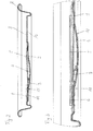
- the somewhat enlarged partial view Fig. 3 shows, in addition to the design of the connection point 7 in the manner of a rivet bond, above all the full-surface attachment of the plastic film 10 on the underside of the can lid and in particular the formation of the weakening line 11 in the plastic film 10, which is preferably achieved by notching and / or area-wise notching, depending on the Embodiment extends inside or outside the micro-gap around the opening area 4.
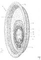
- FIG. 4 shows the design features already described in a particularly illustrative manner and also reveals that the ring tab 5 forming the longer lever arm can be conveniently gripped with a finger due to a recess provided in the cover surface 3 and can be pivoted upwards for the opening process.
- the shorter lever 6 is supported on the stiffened area 14, as a result of which, in the course of pulling up the ring tab, the opening area 4, with simultaneous and now without chip formation, the particularly positive coupling of the lid surface 3 and tongue tab 4 and with separation and the solution of the plastic film on the underside of the lid is opened.
- the ring tab 5 and the opening area 3 pulled up with it are in the free right area of the can lid on the in Fig. 4 below the free end of the ring bracket pivoted pivot area 9 and remain there with the can open.
- closure and opening system described for a can lid can also be used in an analogous manner for other containers and packaging which are to be equipped with a zipper.
Landscapes
- Engineering & Computer Science (AREA)
- Mechanical Engineering (AREA)
- Containers Opened By Tearing Frangible Portions (AREA)
- Closures For Containers (AREA)
- Finger-Pressure Massage (AREA)
Description
- Die Erfindung betrifft einen Dosendeckel, insbesondere für Getränkedosen, mit einem im metallischen Deckelmaterial einer Deckelfläche vorgesehenen begrenzten Öffnungsbereich, sowie einem zum Öffnen dieses Öffnungsbereichs bestimmten zweiarmigen Hebelorgan, das mit dem Deckelmaterial fest, insbesondere über eine Vernietung oder Verschweißung verbunden ist.
- Dosendeckel dieser Art werden weltweit in äußerst großem Umfang verwendet. Sie sind einfach und kostengünstig herstellbar und ermöglichen eine raumsparende Stapelung von Dosen sowie ein Öffnen der Dosen durch einfaches Hochschwenken des langen Arms des Hebelorgans. Diese allgemein bekannten Dosendeckel weisen jedoch einige gravierende Nachteile auf, die vor allem darin bestehen, dass das zunächst flach auf der Deckelfläche liegende Hebelteil nicht einfach zu ergreifen ist, dass beim Hochschwenken des Hebelorgans und dem dabei erfolgenden Öffnen der Dose der den Öffnungsbereich zunächst verschließende Deckelteilbereich in das Doseninnere gedrückt wird und dort mit der Flüssigkeit in Berührung kommt, was hygienisch nicht einwandfrei ist, und dass beim Öffnungsvorgang, d.h. dann, wenn die vorhandene Schwächungsnut zwischen dem Öffnungsbereich und der Deckelfläche aufgerissen bzw. durchtrennt wird, unvermeidbar winzige Aluminiumteilchen aus dem Deckelmaterial frei werden und auch direkt oder über den in das Doseninnere gedrückten Deckelteilbereich in die Dose gelangen. Diese winzigen Späne bzw. Aluminiumpartikel sind in gesundheitlicher Hinsicht bedenklich, wenn sie zusammen mit dem Getränk in den menschlichen Körper gelangen.
-
WO 2015/104659 offenbart einen Dosendeckel nach dem Oberbegriff des Anspruchs 1. - Aufgabe der vorliegenden Erfindung ist es, einen Dosendeckel der eingangs genannten Art ohne zumindest einem der vorstehend genannten Nachteile zu schaffen, d.h. insbesondere einen Dosendeckel, der sich im Vergleich zu den herkömmlichen Dosendeckeln mit wesentlich geringerem Kraftaufwand und in der Handhabung einfacher öffnen lässt, hygienisch einwandfrei ist und vor allem das Auftreten von Aluminiumspänen bzw. Aluminium-Mikropartikelchen beim Öffnungsvorgang ausschließt. Ansonsten soll eine mit dem erfindungsgemäßen Deckel versehene Dose hinsichtlich der Aufbewahrung des jeweiligen Inhalts, der Fertigungs-, Transport- und Handlingeigenschaften den herkömmlichen Dosen entsprechen.
- Gelöst wird diese Aufgabe nach einer ersten Ausführungsform der Erfindung im Wesentlichen dadurch, dass der Öffnungsbereich als Zungenlasche ausgebildet ist, die von der Deckelfläche durch einen sich über den Laschenumfang erstreckenden Mikrospalt, insbesondere einen Stanzspalt, getrennt ist und die mit der Deckelfläche verbundene Zungenlaschenbasis ein beim Öffnungsvorgang wirksam werdendes Knicklager bildet, und dass die Beschichtung dem Mikrospalt zwischen Zungenlasche und Deckelfläche benachbart geschwächt ausgeführt, insbesondere eingekerbt und vorzugsweise wenigstens teilweise durchgekerbt ist. Von besonderer Bedeutung ist bei dieser Ausführungsform der Erfindung das Zusammenwirken zwischen dem vorgesehenen Mikrospalt und der an der Deckelunterseite vorgesehenen Kunststofffolie, die dem Mikrospalt zwischen Zungenlasche und Deckelfläche benachbart so geschwächt bzw. eingekerbt ist, dass einerseits das Öffnen der Dose über den zweiarmigen Hebel mit überraschend geringer Kraft möglich und andererseits trotzdem die Anforderungen an die Dichtheit der Dose sicher gewährleistet ist. Der Mikrospalt wird dabei vorzugsweise durch einen Stanzvorgang mit anschließender Rückführung der durch das Stanzen aus dem Dosendeckelmaterial gedrückten Zungenlasche in ihre Ausgangsposition vor dem Stanzen erhalten. Das leichte, d.h. mit geringer Kraft mögliche Öffnen der Dose ist eine Folge davon, dass kein Durchtrennen von Metall nötig ist und die unterseitige Folie aufgrund der Kerbung während des Öffnens nur in einem sehr schmalen Bereich abgeschält wird.
- Nach einer Ausgestaltung des vorstehenden Grundprinzips des Zusammenwirkens von Mikrospalt und an der Deckelunterseite vorgesehenen Kunststoffbeschichtung ist das zweiarmige Hebelorgan an der Deckelfläche befestigt und der kurze Hebelarm verschwenkt die Zungenlasche beim Öffnungsvorgang zusammen mit dem sie unterseitig bedeckenden, durch die Schwächungslinie begrenzten Teilbereich der Kunststoffbeschichtung in das Doseninnere, wobei dies dadurch ermöglicht wird, dass die Kerbungslinie außerhalb des Mikrospalts gelegen ist.
- Damit wird jegliche störende Spanbildung beim Öffnungsvorgang ausgeschlossen und ein mit geringer Kraft mögliches Öffnen der Dose sichergestellt.
- Eine bevorzugte Weiterbildung des erfindungsgemäßen Grundprinzips besteht darin, dass das zweiarmige Hebelorgan an der Zungenlasche befestigt und mit seinem kurzen Hebelarm auf der Deckelfläche, insbesondere auf einem Versteifungsbereich der Deckelfläche abstützbar ist, und dass der lange Hebelarm die Zungenlasche beim Öffnungsvorgang zusammen mit dem sie unterseitig bedeckenden, durch die innerhalb des Mikrospalts angeordnete Schwächungslinie begrenzten Teilbereich der Kunststoffbeschichtung nach außen verschwenkt.
- Diese Ausführungsform vereint alle erreichbaren Vorteile der Erfindung in sich, da im Vergleich zu den herkömmlichen Dosendeckeln der Öffnungsvorgang einen wesentlich geringeren Kraftaufwand erfordert, das Auftreten von Aluminiumspänen bzw. Aluminium-Mikropartikelchen beim Öffnungsvorgang völlig vermieden wird und außerdem in hygienischer Hinsicht ein Optimum erzielt wird, da ein Eintauchen von Dosendeckelteilen ein in den Doseninnenraum und damit in die sich in der Dose befindende Flüssigkeit verhindert wird.
- Eine für alle Ausführungsvarianten vorteilhafte Ausgestaltung der Erfindung zeichnet sich dadurch aus, dass die Zungenlasche des metallischen Dosendeckels von der ihn umgebenden Deckelfläche unter Ausbildung ineinandergreifender Vorsprünge und Ausnehmungen durch einen Schneid-, insbesondere einen Stanzvorgang getrennt ist, und dass die Zungenlasche und die an diese angrenzende Deckelfläche über die Vorsprünge und Ausnehmungen form- und kraftschlüssig unter Ausbildung des Mikrospalts verbunden sind, wobei die Dichtheit des fertigen, ungeöffneten Dosendeckels durch die innenliegende Kunststoffbeschichtung bzw. Folie gewährleistet ist. Verbessert wird das Dichtvermögen gegenüber Doseninnendruck noch durch eine konkave Ausbildung der Zungenlasche.
- Die Vorsprünge und die Ausnehmungen sind bevorzugt über Hinterschneidungen gekoppelt.
- Insbesondere bei der Ausführungsvariante, bei der die Zungenlasche beim Öffnungsvorgang nach außen bewegt wird, ist der längere Arm des zweiarmigen Hebelorgans von einer Grifflasche, insbesondere einer Ringlasche gebildet und das zweiarmige Hebelorgan mit der Zungenlasche außermittig, insbesondere randseitig verbunden.
- Die Erfindung umfasst neben den im Einzelnen beschriebenen Dosendeckeln auch alle Dosen, die mit einem erfindungsgemäßen Dosendeckel versehen sind, welcher bevorzugt mit der jeweiligen Dose über einen jeweiligen Bördelrand verbunden ist, wobei insbesondere die deckelunterseitig vorgesehene Kunststofffolie im Verbindungsbereich zwischen Dosendeckel und Dose Dichtfunktion übernimmt und die gezielt positionierte Kerbung das Öffnen mit geringer Kraft ermöglicht.
- Ein bevorzugtes Ausführungsbeispiel der Erfindung wird nachfolgend anhand der Zeichnung erläutert; in der Zeichnung zeigt:
- Fig. 1
- eine schematische Draufsicht eines Dosendeckels im geschlossenen Zustand,
- Fig. 2
- eine Schnittdarstellung längs eines Durchmessers des Dosendeckels nach
Fig. 1 , - Fig. 3
- eine vergrößerte Teildarstellung der Schnittansicht nach
Fig. 2 und - Fig. 4
- eine perspektivische Schrägansicht des Dosendeckels von oben.
-
Fig. 1 zeigt eine Ausführungsform des erfindungsgemäßen Dosendeckels 1 in einer schematischen Draufsicht. An seinem Umfangsbereich ist dieser Dosendeckel in herkömmlicher Weise mit einem Bördelrand 2 versehen, wobei der innerhalb des Bördelrandes 2 liegende Bereich von einer Deckelfläche 3 gebildet wird, die bezüglich der Mitte versetzt einen als Zungenlasche ausgebildeten Öffnungsbereich 4 aufweist. Dieser metallische, aus Aluminiummaterial bestehende Dosendeckel ist den Öffnungsbereich 4 umgebend mit einem durch Materialverformung gebildeten Versteifungsbereich 14 versehen. - Mit dem Öffnungsbereich 4 bzw. der Zungenlasche des Dosendeckels ist ein zweiarmiger Hebel 5, 6 verbunden, insbesondere vernietet oder verschweißt, so dass sich eine feste Verbindungsstelle 7 ergibt. Diese Verbindungsstelle 7 liegt im Randbereich des Öffnungsbereichs 4, d.h. gegenüber der mit der Deckelfläche (3) verbundenen Zungenbasis, und der zweiarmige Hebel besteht aus einem kürzeren und einem längeren Bereich, wobei der längere Hebel bevorzugt von einer gut ergreifbaren Ringlasche 5 und der kürzere Bereich von einem Abstützschenkel 6 gebildet wird, der beim Hochschwenken des längeren Hebels sich auf einem Teil des Versteifungsbereichs 14 des Dosendeckels abstützt. Der zweiarmige Hebel 5, 6 liegt im Ausgangszustand im Wesentlichen parallel zur Deckelfläche 3.
- Die den Öffnungsbereich 4 bildende Zungenlasche ist form- und kraftschlüssig über Vorsprünge 12 und Ausnehmungen 13 und bevorzugt über geeignete Hinterschneidungen dieser Teile mit der Deckelfläche 3 verbunden, und zwar mit Ausnahme des Bereichs der Zungenbasis 7, wo Öffnungsbereich 4 und Deckelfläche 3 metallisch verbunden sind, so dass praktisch über eine Art Knickgelenk 9 beim Öffnen der Dose ein Hochschwenken der Zungenlasche 3 mittels des Hebels ermöglicht wird und dann Zungenlasche und Hebel außerhalb des Doseninnenraums unter Freigabe der Öffnung in eine Ruhestellung gelangen können.
- Die geforderte Dichtheit des Dosendeckels wird trotz der fehlenden durchgehenden metallischen Verbindung zwischen Deckelfläche 3 und Öffnungsbereich 4 im Bereich der Verzahnung durch ein an der Unterseite des metallischen Deckels insbesondere vollflächig angebrachtes Kunststoffmaterial, insbesondere eine geeignete Kunststofffolie, gewährleistet, die fest haftend an der Deckelunterseite angebracht bzw. aufgesiegelt ist. Diese Beschichtung besitzt unmittelbar benachbart und innerhalb der Öffnungslinie bzw. des Mikrospalts eine ausgeprägte Schwächung 14, insbesondere eine Ein- oder teilweise Durchkerbung, so dass beim Öffnen des Dosendeckels und dem Hochziehen der Zungenlasche 4 der schmale,3 den Mikrospalt überdeckende Bereich der Kunststofffolie praktisch vom Metall abgeschält und somit ein mit geringem Kraftaufwand erfolgendes Öffnen der Dose ermöglicht wird.
- Um diese beim Öffnen des Dosendeckels jegliche Metallspanbildung ausschließende Gestaltung zu erreichen, wird bei der Fertigung des Dosendeckels der Öffnungsbereich bzw. die Zungenlasche durch einen Schneid- oder vorzugsweise einen Stanzvorgang die Zungenlasche von der umgebenden Deckelfläche getrennt, wobei die dabei entstehenden Späne oder Mikropartikelchen im Rahmen des Fertigungsvorgangs vollständig und problemlos beseitigt werden können. Die Zungenlasche, die über ihre Basis noch mit der Deckelfläche 3 verbunden ist, wird unmittelbar nach ihrer Ausstanzung zurück in die Deckelflächenebene gedrückt, so dass sich für die Deckelfläche praktisch wieder das ursprüngliche Erscheinungsbild ergibt, jedoch nunmehr mit einem durch den Stanzvorgang erzeugten Mikrospalt.
- Anstelle eines linienförmigen Mikrospalts werden beim Stanzvorgang bevorzugt ineinandergreifende Vorsprünge 12 und Ausnehmungen 13 erzeugt, wie dies der
Fig. 1 zu entnehmen ist. - In diesem Fall werden unmittelbar nach dem Stanzvorgang die beiden zunächst zum Teil getrennten Komponenten wieder formschlüssig ineinandergefügt, so dass der Dosendeckel in weiteren Fertigungsschritten in gleicher Weise gehandhabt werden kann wie herkömmliche Dosendeckel, die lediglich eine Schwächungsnut aufweisen.
- Die Vorgänge des Trennens und des Ineinanderfügens erfolgen direkt nacheinander, d.h. auf den Stanzhub erfolgt im Rückhub das formschlüssige Zusammenführen beider Teile zu einem Gesamtteil. Die form- und kraftschlüssige Verbindung zwischen den beiden Bereichen wird durch geeignete Formgebung bzw. durch Verwendung von Hinterschneidungen erreicht, die eine ausreichende gegenseitige mechanische Verbindung gewährleistet, so dass dann auch die notwendigen Beschichtungsvorgänge bzw. der Vorgang des unterseitigen Aufbringens der Folie wie bei einem einheitlichen Teil durchgeführt werden können.
- Anstelle der in der Zeichnung gezeigten Verzahnung können erfindungsgemäß auch andere, gegebenenfalls einfachere Spaltlinienverläufe beim Stanzvorgang vorgesehen werden, wobei aber in jedem Falle der Öffnungsbereich bzw. die Zungenlasche mit der Deckelfläche 3 über den Knicklagerbereich 9 verbunden bleibt und der Mikrospalt durch die innenseitig gelegene, mit einer Kerbung versehene Kunststofffolie abgedeckt ist. Die Kunststofffolie, bei der es sich um einen PP-Folie handeln kann, die beim Aufsiegeln mit dem am Metall vorgesehenen Siegellack reagiert, wird insbesondere als eigenständiges Blisterformteil hergestellt, in dem bereits die Kerbung vorgesehen ist. Wenn die Folie z.B. eine Dicke von etwa 2/10 mm beträgt, erfolgt in der Kerbung ein Schwächung auf 1/100 mm.
- Die etwas vergrößerte Teildarstellung nach
Fig. 3 zeigt neben der Ausgestaltung der Verbindungsstelle 7 nach Art einer Nietbindung vor allem die vollflächige Anbringung der Kunststofffolie 10 an der Unterseite des Dosendeckels und insbesondere die bevorzugt durch eine Kerbung und/oder bereichsweise Durchkerbung erreichte Ausbildung der Schwächungslinie 11 in der Kunststofffolie 10, die sich je nach Ausführungsform innerhalb oder außerhalb des Mikrospalts um den Öffnungsbereich 4 erstreckt. - Die perspektivische Darstellung nach
Fig. 4 zeigt die bereits beschriebenen Gestaltungsmerkmale in besonders anschaulicher Weise und lässt auch erkennen, dass die den längeren Hebelarm bildende Ringlasche 5 aufgrund einer vorgesehenen Vertiefung in der Deckelfläche 3 bequem mit einem Finger untergriffen und zum Öffnungsvorgang nach oben geschwenkt werden kann. Bei diesem Hochschwenken der Grifflasche 5 stützt sich der kürzere Hebel 6 an dem versteiften Bereich 14 ab, wodurch im Verlauf des Hochziehens der Ringlasche der Öffnungsbereich 4 unter gleichzeitiger und jetzt ohne Spanbildung erfolgender Lösung der insbesondere formschlüssigen Kopplung von Deckelfläche 3 und Zungenlasche 4 und unter Trennung und Lösung der an der Unterseite des Deckels vorhandenen Kunststofffolie die Dose geöffnet wird. - Die Ringlasche 5 und der mit ihr hochgezogene Öffnungsbereich 3 werden in den freien rechten Bereich des Dosendeckels über den in
Fig. 4 unterhalb des freien Endes der Ringlasche gelegenen Knicklagerbereich 9 verschwenkt und verbleiben dort bei geöffneter Dose. - Wie geschildert, werden auf diese Weise sämtliche Nachteile des bisher bekannten und weit verbreiteten Dosendeckels vermieden, insbesondere vor allem die gesundheitsgefährdende Bildung von winzigen Mikro-Aluminiumpartikeln bei der Dosenöffnung. Von besonderer Bedeutung ist dabei, dass all diese Vorteile ohne wesentlichem fertigungstechnischen Mehraufwand erhalten werden.
- Das für einen Dosendeckel beschriebene Verschluss- und Öffnungssystem ist in analoger Weise auch für sonstige Gefäße und Verpackungen verwendbar, die mit einem Aufreißverschluss ausgestattet sein sollen.
-
- 1
- Dosendeckel
- 2
- Bördelrand
- 3
- Deckelfläche
- 4
- Öffnungsbereich, Zungenlasche
- 5
- Hebelarm
- 6
- Hebelarm
- 7
- Befestigungsstelle, Zungenbasis
- 8
- Mikrospalt
- 9
- Knicklagerbereich
- 10
- Kunststofffolie
- 11
- Schwächungslinie, Einkerbung
- 12
- Vorsprung
- 13
- Ausnehmung
- 14
- Versteifungsbereich
Claims (10)
- Dosendeckel, insbesondere für Getränkedosen,
mit einem im metallischen Deckelmaterial einer Deckelfläche (3) vorgesehenen begrenzten Öffnungsbereich (4),
sowie einem zum Öffnen dieses Öffnungsbereichs (4) bestimmten zweiarmigen Hebelorgan (5, 6),
das mit dem Deckelmaterial fest, insbesondere über eine Vernietung (7) oder Verschweißung verbunden ist,
wobei die Unterseite des metallischen Deckels (1) insbesondere vollflächig mit einem Kunststoffmaterial, insbesondere einer Kunststofffolie (10) festhaftend beschichtet ist,
dadurch gekennzeichnet, dass
der Öffnungsbereich als Zungenlasche (4) ausgebildet ist,
die von der Deckelfläche (3) durch einen sich über den Laschenumfang erstreckenden Mikrospalt (8), insbesondere einen Stanzspalt, getrennt ist und die mit der Deckelfläche (3) verbundene Zungenlaschenbasis ein beim Öffnungsvorgang wirksam werdendes Knicklager (9) bildet, und
dass die Beschichtung (10) dem Mikrospalt (8) zwischen Zungenlasche (4) und Deckelfläche (3) benachbart geschwächt ausgeführt, insbesondere eingekerbt und vorzugsweise wenigstens teilweise durchgekerbt ist. - Dosendeckel nach Anspruch 1,
dadurch gekennzeichnet, dass
das zweiarmige Hebelorgan (5, 6) an der Deckelfläche (3) befestigt ist und der kurze Hebelarm (6) die Zungenlasche (4) beim Öffnungsvorgang zusammen mit dem sie unterseitig bedeckenden, durch die Schwächungslinie (11) begrenzten Teilbereich der Kunststoffbeschichtung (10) in das Doseninnere verschwenkt, wobei die Schwächungs- oder Kerbungslinie (11) außerhalb des Mikrospalts (8) gelegen ist. - Dosendeckel nach Anspruch 1,
dadurch gekennzeichnet, dass
das zweiarmige Hebelorgan (5, 6) an der Zungenlasche (4) befestigt und mit seinem kurzen Hebelarm (6) auf der Deckelfläche (3), insbesondere auf einem Versteifungsbereich (14) der Deckelfläche (3) abstützbar ist, und
dass der lange Hebelarm (5) die Zungenlasche (4) beim Öffnungsvorgang zusammen mit dem sie unterseitig bedeckenden, durch die Schwächungslinie (11) begrenzten Teilbereich der Kunststoffbeschichtung (10) nach außen verschwenkt, wobei die Schwächungs- oder Kerbungslinie (11) innerhalb des Mikrospalts (8) gelegen ist. - Dosendeckel nach einem der vorhergehenden Ansprüche,'
dadurch gekennzeichnet, dass
die Zungenlasche (4) des metallischen Dosendeckels (1) von der ihn umgebenden Deckelfläche (3) unter Ausbildung ineinandergreifender Vorsprünge (12) und Ausnehmungen (13) durch einen Schneid-, insbesondere einen Stanzvorgang getrennt ist, und
dass die Zungenlasche (4) und die an diese angrenzende Deckelfläche (3) über die Vorsprünge (12) und Ausnehmungen (13) form- und kraftschlüssig unter Ausbildung des Mikrospalts (8) verbunden sind, wobei die Dichtheit des fertigen, ungeöffneten Dosendeckels durch die innenliegende Kunststoffbeschichtung bzw. Folie (10) mit einer Dicke vorzugsweise im Bereich von etwa 1/10 mm bis 3/10 mm gewährleistet ist. - Dosendeckel nach Anspruch 4,
dadurch gekennzeichnet, dass
die Vorsprünge (12) und die Ausnehmungen (13) über Hinterschneidungen gekoppelt sind. - Dosendeckel nach Anspruch 4 oder 5,
dadurch gekennzeichnet, dass
die Deckeloberfläche (3) im Bereich der Zungenlasche (4) konkav ausgebildet ist und durch den Behälterinnendruck die Pressung im Mikrospalt erhöht wird. - Dosendeckel nach einem der vorhergehenden Ansprüche,
dadurch gekennzeichnet, dass
die an der Unterseite vorgesehene Kunststofffolie (10) vor ihrer Versiegelung mit der Unterseite ein separates Blisterformteil bildet, in dem die Einkerbung (11) oder teilweise Durchkerbung bereits vorgesehen ist. - Dosendeckel nach Anspruch 3,
dadurch gekennzeichnet, dass
das zweiarmige Hebelorgan (5, 6) mit der Zungenlasche (4) außermittig, insbesondere randseitig verbunden ist. - Dosendeckel nach Anspruch 8,
dadurch gekennzeichnet, dass
der längere Arm (5) des zweiarmigen Hebelorgans (5, 6) von einer Grifflasche, insbesondere einer Ringlasche gebildet ist. - Dose mit einem über einen Bördelrand mit der Dose verbundenen Dosendeckel nach einem oder mehreren der vorhergehenden Ansprüche.
Priority Applications (4)
| Application Number | Priority Date | Filing Date | Title |
|---|---|---|---|
| SI201630687T SI3377417T1 (sl) | 2015-12-22 | 2016-11-10 | Pokrov pločevinke |
| RS20200379A RS60228B1 (sr) | 2015-12-22 | 2016-11-10 | Poklopac limenke |
| HRP20200486TT HRP20200486T1 (hr) | 2015-12-22 | 2016-11-10 | Poklopac za limenke |
| PL16794325T PL3377417T3 (pl) | 2015-12-22 | 2016-11-10 | Pokrywka puszki |
Applications Claiming Priority (2)
| Application Number | Priority Date | Filing Date | Title |
|---|---|---|---|
| DE102015122548.4A DE102015122548A1 (de) | 2015-12-22 | 2015-12-22 | Dosendeckel |
| PCT/EP2016/077249 WO2017108260A1 (de) | 2015-12-22 | 2016-11-10 | Dosendeckel |
Publications (2)
| Publication Number | Publication Date |
|---|---|
| EP3377417A1 EP3377417A1 (de) | 2018-09-26 |
| EP3377417B1 true EP3377417B1 (de) | 2020-01-29 |
Family
ID=57281221
Family Applications (1)
| Application Number | Title | Priority Date | Filing Date |
|---|---|---|---|
| EP16794325.7A Active EP3377417B1 (de) | 2015-12-22 | 2016-11-10 | Dosendeckel |
Country Status (25)
| Country | Link |
|---|---|
| US (1) | US10549882B2 (de) |
| EP (1) | EP3377417B1 (de) |
| JP (1) | JP7086846B2 (de) |
| KR (1) | KR102167947B1 (de) |
| CN (1) | CN108602585B (de) |
| AU (1) | AU2016378603B2 (de) |
| BR (1) | BR112018012709B1 (de) |
| CA (1) | CA3008237C (de) |
| CY (1) | CY1122819T1 (de) |
| DE (1) | DE102015122548A1 (de) |
| DK (1) | DK3377417T3 (de) |
| EA (1) | EA033945B1 (de) |
| ES (1) | ES2779825T3 (de) |
| HR (1) | HRP20200486T1 (de) |
| HU (1) | HUE048495T2 (de) |
| LT (1) | LT3377417T (de) |
| MA (1) | MA43249B1 (de) |
| MX (1) | MX2018007683A (de) |
| PL (1) | PL3377417T3 (de) |
| PT (1) | PT3377417T (de) |
| RS (1) | RS60228B1 (de) |
| SA (1) | SA518391837B1 (de) |
| SI (1) | SI3377417T1 (de) |
| WO (1) | WO2017108260A1 (de) |
| ZA (1) | ZA201803724B (de) |
Families Citing this family (11)
| Publication number | Priority date | Publication date | Assignee | Title |
|---|---|---|---|---|
| USD1033215S1 (en) | 2012-08-10 | 2024-07-02 | Daniel A. Zabaleta | Container lid comprising frustum shaped sidewall and seaming chuck receiving radius |
| USD828753S1 (en) * | 2012-08-10 | 2018-09-18 | Daniel A Zabaleta | Axially oriented peripheral sidewalled beverage container lid |
| US12365511B1 (en) | 2012-08-10 | 2025-07-22 | Daniel A Zabaleta | Sealing cap having tamper evidence ring for sealing resealable container and method of use |
| USD1033216S1 (en) | 2012-08-10 | 2024-07-02 | Daniel A. Zabaleta | Container cap having frustum shaped sidewall segment enabling nesting |
| US10968010B1 (en) | 2012-08-10 | 2021-04-06 | Daniel A Zabaleta | Resealable container lid and accessories including methods of manufacture and use |
| PT3385185T (pt) | 2017-04-05 | 2020-08-18 | Gregor Anton Piech | Tampa de lata metálica |
| EP3546199A1 (de) | 2018-03-28 | 2019-10-02 | Top Cap Holding GmbH | Verfahren zum herstellen eines dosendeckels aus einem verbundmaterial |
| FI3741701T3 (fi) * | 2018-06-19 | 2023-03-18 | Top Cap Holding Gmbh | Menetelmä metallisen tölkinkannen valmistamiseksi |
| CN112763281A (zh) * | 2020-12-29 | 2021-05-07 | 北京方鸿智能科技有限公司 | 采样片 |
| US12384594B2 (en) | 2021-04-05 | 2025-08-12 | Daniel A. Zabaleta | Threaded container components having frustum shaped surfaces enabling nesting |
| DE102021131239A1 (de) * | 2021-11-29 | 2023-06-01 | Top Cap Holding Gmbh | Dosendeckel und Verfahren zum Herstellen eines Dosendeckels |
Family Cites Families (19)
| Publication number | Priority date | Publication date | Assignee | Title |
|---|---|---|---|---|
| US3342367A (en) * | 1965-10-20 | 1967-09-19 | Continental Can Co | Window can end unit |
| US3952912A (en) * | 1972-03-02 | 1976-04-27 | Walter Merton Perry | Container with attached closure |
| US3964670A (en) * | 1974-12-09 | 1976-06-22 | The Procter & Gamble Company | Closure |
| BR7908691A (pt) | 1978-05-22 | 1980-12-30 | N Waterbury | Fecho articulado |
| DE3235167A1 (de) * | 1982-09-23 | 1984-03-29 | Robert Bosch Gmbh, 7000 Stuttgart | Behaelterdeckel mit oeffnungseinrichtung |
| DE3639426C1 (de) * | 1986-11-18 | 1987-10-01 | Rasselstein Ag | Dosendeckel aus Blech fuer Dosen,deren Inhalt unter Innendruck steht |
| GB9321118D0 (en) * | 1993-10-13 | 1993-12-01 | Metal Box Plc | Closure |
| IT1280461B1 (it) * | 1995-09-11 | 1998-01-20 | Cesare Mongarli | Contenitore, particolarmente per bevande. |
| DE19629148C2 (de) * | 1996-07-19 | 2002-10-24 | Mars Inc | Verfahren zur Herstellung eines befüllten Behälters |
| JP2003095264A (ja) * | 2001-09-18 | 2003-04-03 | Mitsubishi Materials Corp | 開口容易なラミネート缶蓋 |
| JP4803648B2 (ja) | 2005-09-01 | 2011-10-26 | 大和製罐株式会社 | ステイオンタブ方式の開口容易缶蓋 |
| US20070284374A1 (en) | 2006-06-13 | 2007-12-13 | Kou-An Chen | Structure of a lid of easy open can |
| CA2721263C (en) * | 2008-04-24 | 2016-04-05 | Tomoyuki Shibata | Compound container and pouring-out method |
| MX2011008053A (es) * | 2009-01-30 | 2012-01-12 | Dow Global Technologies Llc | Composiciones de polietileno de alta densidad, metodo para producir las mismas, dispositivos de cierre elaborados de las mismas, y metodo para elaborar dichos dispositivos de cierre. |
| EP2253552A1 (de) | 2009-04-23 | 2010-11-24 | Crown Packaging Technology, Inc | Dosenende |
| US8695832B2 (en) * | 2010-02-02 | 2014-04-15 | Klaus Thielen | Can lid and method for producing a can lid |
| BR112012025469B1 (pt) * | 2010-04-06 | 2020-04-07 | C2C Beteiligungs Gmbh | dispositivo de fecho para recipiente e recipiente com um fecho desta espécie |
| WO2013022592A1 (en) * | 2011-08-11 | 2013-02-14 | Stolle Machinery Company, Llc | Can end, double action tab therefor, tooling assembly, and associated method |
| CA2936325C (en) * | 2014-01-08 | 2022-11-29 | International Patents And Brands Corporation | Lid for containers of substances and container of substances comprising said lid |
-
2015
- 2015-12-22 DE DE102015122548.4A patent/DE102015122548A1/de not_active Withdrawn
-
2016
- 2016-11-10 HR HRP20200486TT patent/HRP20200486T1/hr unknown
- 2016-11-10 HU HUE16794325A patent/HUE048495T2/hu unknown
- 2016-11-10 BR BR112018012709-4A patent/BR112018012709B1/pt active IP Right Grant
- 2016-11-10 JP JP2018533258A patent/JP7086846B2/ja active Active
- 2016-11-10 ES ES16794325T patent/ES2779825T3/es active Active
- 2016-11-10 RS RS20200379A patent/RS60228B1/sr unknown
- 2016-11-10 EP EP16794325.7A patent/EP3377417B1/de active Active
- 2016-11-10 CA CA3008237A patent/CA3008237C/en active Active
- 2016-11-10 US US15/542,828 patent/US10549882B2/en active Active
- 2016-11-10 SI SI201630687T patent/SI3377417T1/sl unknown
- 2016-11-10 CN CN201680075970.5A patent/CN108602585B/zh active Active
- 2016-11-10 PL PL16794325T patent/PL3377417T3/pl unknown
- 2016-11-10 PT PT167943257T patent/PT3377417T/pt unknown
- 2016-11-10 MA MA43249A patent/MA43249B1/fr unknown
- 2016-11-10 DK DK16794325.7T patent/DK3377417T3/da active
- 2016-11-10 WO PCT/EP2016/077249 patent/WO2017108260A1/de not_active Ceased
- 2016-11-10 EA EA201891493A patent/EA033945B1/ru unknown
- 2016-11-10 KR KR1020187017693A patent/KR102167947B1/ko active Active
- 2016-11-10 MX MX2018007683A patent/MX2018007683A/es unknown
- 2016-11-10 LT LTEP16794325.7T patent/LT3377417T/lt unknown
- 2016-11-10 AU AU2016378603A patent/AU2016378603B2/en active Active
-
2018
- 2018-06-05 ZA ZA2018/03724A patent/ZA201803724B/en unknown
- 2018-06-20 SA SA518391837A patent/SA518391837B1/ar unknown
-
2020
- 2020-04-28 CY CY20201100386T patent/CY1122819T1/el unknown
Non-Patent Citations (1)
| Title |
|---|
| None * |
Also Published As
Similar Documents
| Publication | Publication Date | Title |
|---|---|---|
| EP3377417B1 (de) | Dosendeckel | |
| EP3408184B1 (de) | Dosendeckel wiederverschliessbar | |
| EP1768916B1 (de) | Verfahren zum ablösen bzw. abtrennen einer auf den rand des halses einer flasche aufgesiegelten siegelfolie und schraubkappe zur ausführung dieses verfahrens | |
| EP3310675B1 (de) | Dosendeckel | |
| EP3385184B1 (de) | Behältnis zum hermetisch dichten aufbewahren von produkten, insbesondere von lebensmitteln | |
| EP3484783B1 (de) | Metallische dose | |
| EP3929101B1 (de) | Metallischer dosendeckel | |
| EP3680191B1 (de) | Verfahren zur herstellung einer öffnung in einem flächigen blechmaterial | |
| DE1432141A1 (de) | Behaelterdeckel | |
| EP3741701B1 (de) | Verfahren zur herstellung eines metallischen dosendeckels | |
| EP4228976B1 (de) | Dosendeckel und verfahren zum herstellen eines dosendeckels | |
| EP2070826B1 (de) | Behälter mit leicht zu öffnendem Verschlusselement | |
| DE3249720C2 (de) | ||
| DE3212990C2 (de) | ||
| EP0921985B1 (de) | Verfahren zur herstellung eines befüllten behälters |
Legal Events
| Date | Code | Title | Description |
|---|---|---|---|
| STAA | Information on the status of an ep patent application or granted ep patent |
Free format text: STATUS: UNKNOWN |
|
| STAA | Information on the status of an ep patent application or granted ep patent |
Free format text: STATUS: THE INTERNATIONAL PUBLICATION HAS BEEN MADE |
|
| PUAI | Public reference made under article 153(3) epc to a published international application that has entered the european phase |
Free format text: ORIGINAL CODE: 0009012 |
|
| STAA | Information on the status of an ep patent application or granted ep patent |
Free format text: STATUS: REQUEST FOR EXAMINATION WAS MADE |
|
| 17P | Request for examination filed |
Effective date: 20180620 |
|
| AK | Designated contracting states |
Kind code of ref document: A1 Designated state(s): AL AT BE BG CH CY CZ DE DK EE ES FI FR GB GR HR HU IE IS IT LI LT LU LV MC MK MT NL NO PL PT RO RS SE SI SK SM TR |
|
| AX | Request for extension of the european patent |
Extension state: BA ME |
|
| DAX | Request for extension of the european patent (deleted) | ||
| RAV | Requested validation state of the european patent: fee paid |
Extension state: MA Effective date: 20180620 |
|
| GRAP | Despatch of communication of intention to grant a patent |
Free format text: ORIGINAL CODE: EPIDOSNIGR1 |
|
| STAA | Information on the status of an ep patent application or granted ep patent |
Free format text: STATUS: GRANT OF PATENT IS INTENDED |
|
| INTG | Intention to grant announced |
Effective date: 20190708 |
|
| RAP1 | Party data changed (applicant data changed or rights of an application transferred) |
Owner name: PIECH, GREGOR ANTON |
|
| GRAS | Grant fee paid |
Free format text: ORIGINAL CODE: EPIDOSNIGR3 |
|
| GRAJ | Information related to disapproval of communication of intention to grant by the applicant or resumption of examination proceedings by the epo deleted |
Free format text: ORIGINAL CODE: EPIDOSDIGR1 |
|
| GRAL | Information related to payment of fee for publishing/printing deleted |
Free format text: ORIGINAL CODE: EPIDOSDIGR3 |
|
| STAA | Information on the status of an ep patent application or granted ep patent |
Free format text: STATUS: REQUEST FOR EXAMINATION WAS MADE |
|
| GRAR | Information related to intention to grant a patent recorded |
Free format text: ORIGINAL CODE: EPIDOSNIGR71 |
|
| STAA | Information on the status of an ep patent application or granted ep patent |
Free format text: STATUS: GRANT OF PATENT IS INTENDED |
|
| REG | Reference to a national code |
Ref country code: HK Ref legal event code: DE Ref document number: 1260419 Country of ref document: HK |
|
| INTC | Intention to grant announced (deleted) | ||
| GRAA | (expected) grant |
Free format text: ORIGINAL CODE: 0009210 |
|
| STAA | Information on the status of an ep patent application or granted ep patent |
Free format text: STATUS: THE PATENT HAS BEEN GRANTED |
|
| INTG | Intention to grant announced |
Effective date: 20191212 |
|
| AK | Designated contracting states |
Kind code of ref document: B1 Designated state(s): AL AT BE BG CH CY CZ DE DK EE ES FI FR GB GR HR HU IE IS IT LI LT LU LV MC MK MT NL NO PL PT RO RS SE SI SK SM TR |
|
| REG | Reference to a national code |
Ref country code: GB Ref legal event code: FG4D Free format text: NOT ENGLISH |
|
| REG | Reference to a national code |
Ref country code: CH Ref legal event code: EP |
|
| REG | Reference to a national code |
Ref country code: AT Ref legal event code: REF Ref document number: 1228364 Country of ref document: AT Kind code of ref document: T Effective date: 20200215 |
|
| REG | Reference to a national code |
Ref country code: IE Ref legal event code: FG4D Free format text: LANGUAGE OF EP DOCUMENT: GERMAN |
|
| REG | Reference to a national code |
Ref country code: DE Ref legal event code: R096 Ref document number: 502016008573 Country of ref document: DE |
|
| REG | Reference to a national code |
Ref country code: RO Ref legal event code: EPE |
|
| REG | Reference to a national code |
Ref country code: CH Ref legal event code: NV Representative=s name: DR. GRAF AND PARTNER AG INTELLECTUAL PROPERTY, CH |
|
| REG | Reference to a national code |
Ref country code: HR Ref legal event code: TUEP Ref document number: P20200486T Country of ref document: HR |
|
| REG | Reference to a national code |
Ref country code: DK Ref legal event code: T3 Effective date: 20200325 Ref country code: PT Ref legal event code: SC4A Ref document number: 3377417 Country of ref document: PT Date of ref document: 20200330 Kind code of ref document: T Free format text: AVAILABILITY OF NATIONAL TRANSLATION Effective date: 20200319 |
|
| REG | Reference to a national code |
Ref country code: FI Ref legal event code: FGE |
|
| REG | Reference to a national code |
Ref country code: SE Ref legal event code: TRGR |
|
| REG | Reference to a national code |
Ref country code: NL Ref legal event code: FP |
|
| REG | Reference to a national code |
Ref country code: MA Ref legal event code: VAGR Ref document number: 43249 Country of ref document: MA Kind code of ref document: B1 |
|
| REG | Reference to a national code |
Ref country code: NO Ref legal event code: T2 Effective date: 20200129 |
|
| RAP2 | Party data changed (patent owner data changed or rights of a patent transferred) |
Owner name: PIECH, GREGOR ANTON |
|
| REG | Reference to a national code |
Ref country code: EE Ref legal event code: FG4A Ref document number: E018938 Country of ref document: EE Effective date: 20200305 |
|
| REG | Reference to a national code |
Ref country code: GR Ref legal event code: EP Ref document number: 20200401164 Country of ref document: GR Effective date: 20200615 |
|
| REG | Reference to a national code |
Ref country code: HR Ref legal event code: T1PR Ref document number: P20200486 Country of ref document: HR |
|
| REG | Reference to a national code |
Ref country code: DE Ref legal event code: R081 Ref document number: 502016008573 Country of ref document: DE Owner name: PIECH, GREGOR ANTON, AT Free format text: FORMER OWNER: PIECH, GREGOR ANTON, ELLMAU, AT Ref country code: DE Ref legal event code: R082 Ref document number: 502016008573 Country of ref document: DE Representative=s name: MANITZ FINSTERWALD PATENT- UND RECHTSANWALTSPA, DE |
|
| REG | Reference to a national code |
Ref country code: HU Ref legal event code: AG4A Ref document number: E048495 Country of ref document: HU |
|
| REG | Reference to a national code |
Ref country code: SK Ref legal event code: T3 Ref document number: E 34346 Country of ref document: SK |
|
| REG | Reference to a national code |
Ref country code: ES Ref legal event code: FG2A Ref document number: 2779825 Country of ref document: ES Kind code of ref document: T3 Effective date: 20200820 |
|
| PG25 | Lapsed in a contracting state [announced via postgrant information from national office to epo] |
Ref country code: SM Free format text: LAPSE BECAUSE OF FAILURE TO SUBMIT A TRANSLATION OF THE DESCRIPTION OR TO PAY THE FEE WITHIN THE PRESCRIBED TIME-LIMIT Effective date: 20200129 |
|
| REG | Reference to a national code |
Ref country code: DE Ref legal event code: R097 Ref document number: 502016008573 Country of ref document: DE |
|
| REG | Reference to a national code |
Ref country code: HR Ref legal event code: ODRP Ref document number: P20200486 Country of ref document: HR Payment date: 20201102 Year of fee payment: 5 |
|
| PLBE | No opposition filed within time limit |
Free format text: ORIGINAL CODE: 0009261 |
|
| STAA | Information on the status of an ep patent application or granted ep patent |
Free format text: STATUS: NO OPPOSITION FILED WITHIN TIME LIMIT |
|
| 26N | No opposition filed |
Effective date: 20201030 |
|
| PG25 | Lapsed in a contracting state [announced via postgrant information from national office to epo] |
Ref country code: MC Free format text: LAPSE BECAUSE OF FAILURE TO SUBMIT A TRANSLATION OF THE DESCRIPTION OR TO PAY THE FEE WITHIN THE PRESCRIBED TIME-LIMIT Effective date: 20200129 |
|
| PG25 | Lapsed in a contracting state [announced via postgrant information from national office to epo] |
Ref country code: LU Free format text: LAPSE BECAUSE OF NON-PAYMENT OF DUE FEES Effective date: 20201110 |
|
| REG | Reference to a national code |
Ref country code: HR Ref legal event code: ODRP Ref document number: P20200486 Country of ref document: HR Payment date: 20211109 Year of fee payment: 6 |
|
| REG | Reference to a national code |
Ref country code: HR Ref legal event code: ODRP Ref document number: P20200486 Country of ref document: HR Payment date: 20221103 Year of fee payment: 7 |
|
| REG | Reference to a national code |
Ref country code: HR Ref legal event code: ODRP Ref document number: P20200486 Country of ref document: HR Payment date: 20231103 Year of fee payment: 8 |
|
| REG | Reference to a national code |
Ref country code: HR Ref legal event code: ODRP Ref document number: P20200486 Country of ref document: HR Payment date: 20241031 Year of fee payment: 9 |
|
| PGFP | Annual fee paid to national office [announced via postgrant information from national office to epo] |
Ref country code: HU Payment date: 20241122 Year of fee payment: 9 |
|
| PGFP | Annual fee paid to national office [announced via postgrant information from national office to epo] |
Ref country code: NO Payment date: 20241125 Year of fee payment: 9 |
|
| PGFP | Annual fee paid to national office [announced via postgrant information from national office to epo] |
Ref country code: GR Payment date: 20241122 Year of fee payment: 9 |
|
| PGFP | Annual fee paid to national office [announced via postgrant information from national office to epo] |
Ref country code: IS Payment date: 20241112 Year of fee payment: 9 |
|
| PGFP | Annual fee paid to national office [announced via postgrant information from national office to epo] |
Ref country code: HR Payment date: 20241031 Year of fee payment: 9 |
|
| PGFP | Annual fee paid to national office [announced via postgrant information from national office to epo] |
Ref country code: SK Payment date: 20241106 Year of fee payment: 9 |
|
| PGFP | Annual fee paid to national office [announced via postgrant information from national office to epo] |
Ref country code: AL Payment date: 20241125 Year of fee payment: 9 |
|
| REG | Reference to a national code |
Ref country code: DE Ref legal event code: R082 Ref document number: 502016008573 Country of ref document: DE Representative=s name: EISENFUEHR SPEISER PATENTANWAELTE RECHTSANWAEL, DE |
|
| PGFP | Annual fee paid to national office [announced via postgrant information from national office to epo] |
Ref country code: CY Payment date: 20241025 Year of fee payment: 9 |
|
| PGFP | Annual fee paid to national office [announced via postgrant information from national office to epo] |
Ref country code: PL Payment date: 20250926 Year of fee payment: 10 |
|
| VSFP | Annual fee paid to validation state [announced via postgrant information from national office to epo] |
Ref country code: MA Payment date: 20231107 Year of fee payment: 8 |
|
| VSFP | Annual fee paid to validation state [announced via postgrant information from national office to epo] |
Ref country code: MA Payment date: 20221027 Year of fee payment: 7 Ref country code: MA Payment date: 20211112 Year of fee payment: 6 Ref country code: MA Payment date: 20201130 Year of fee payment: 5 |
|
| PGFP | Annual fee paid to national office [announced via postgrant information from national office to epo] |
Ref country code: MK Payment date: 20241022 Year of fee payment: 9 |
|
| VSFP | Annual fee paid to validation state [announced via postgrant information from national office to epo] |
Ref country code: MA Payment date: 20241101 Year of fee payment: 9 |
|
| REG | Reference to a national code |
Ref country code: CH Ref legal event code: U11 Free format text: ST27 STATUS EVENT CODE: U-0-0-U10-U11 (AS PROVIDED BY THE NATIONAL OFFICE) Effective date: 20251201 |
|
| PGFP | Annual fee paid to national office [announced via postgrant information from national office to epo] |
Ref country code: PT Payment date: 20251028 Year of fee payment: 10 |
|
| PGFP | Annual fee paid to national office [announced via postgrant information from national office to epo] |
Ref country code: NL Payment date: 20251119 Year of fee payment: 10 |
|
| PGFP | Annual fee paid to national office [announced via postgrant information from national office to epo] |
Ref country code: DE Payment date: 20251201 Year of fee payment: 10 |
|
| PGFP | Annual fee paid to national office [announced via postgrant information from national office to epo] |
Ref country code: LT Payment date: 20251030 Year of fee payment: 10 Ref country code: GB Payment date: 20251120 Year of fee payment: 10 |
|
| PGFP | Annual fee paid to national office [announced via postgrant information from national office to epo] |
Ref country code: AT Payment date: 20251117 Year of fee payment: 10 |
|
| PGFP | Annual fee paid to national office [announced via postgrant information from national office to epo] |
Ref country code: IT Payment date: 20251128 Year of fee payment: 10 Ref country code: FI Payment date: 20251118 Year of fee payment: 10 Ref country code: DK Payment date: 20251119 Year of fee payment: 10 |
|
| PGFP | Annual fee paid to national office [announced via postgrant information from national office to epo] |
Ref country code: FR Payment date: 20251125 Year of fee payment: 10 |
|
| PGFP | Annual fee paid to national office [announced via postgrant information from national office to epo] |
Ref country code: TR Payment date: 20251105 Year of fee payment: 10 Ref country code: BE Payment date: 20251118 Year of fee payment: 10 |
|
| PGFP | Annual fee paid to national office [announced via postgrant information from national office to epo] |
Ref country code: SE Payment date: 20251119 Year of fee payment: 10 Ref country code: CH Payment date: 20251201 Year of fee payment: 10 |
|
| PGFP | Annual fee paid to national office [announced via postgrant information from national office to epo] |
Ref country code: IE Payment date: 20251120 Year of fee payment: 10 Ref country code: CZ Payment date: 20251029 Year of fee payment: 10 |
|
| PGFP | Annual fee paid to national office [announced via postgrant information from national office to epo] |
Ref country code: MT Payment date: 20251124 Year of fee payment: 10 Ref country code: LV Payment date: 20251125 Year of fee payment: 10 |
|
| PGFP | Annual fee paid to national office [announced via postgrant information from national office to epo] |
Ref country code: BG Payment date: 20251114 Year of fee payment: 10 |
|
| PGFP | Annual fee paid to national office [announced via postgrant information from national office to epo] |
Ref country code: EE Payment date: 20251118 Year of fee payment: 10 |
|
| PGFP | Annual fee paid to national office [announced via postgrant information from national office to epo] |
Ref country code: RO Payment date: 20251107 Year of fee payment: 10 |
|
| PGFP | Annual fee paid to national office [announced via postgrant information from national office to epo] |
Ref country code: RS Payment date: 20251106 Year of fee payment: 10 |
|
| PGFP | Annual fee paid to national office [announced via postgrant information from national office to epo] |
Ref country code: SI Payment date: 20251103 Year of fee payment: 10 Ref country code: ES Payment date: 20251216 Year of fee payment: 10 |