EP3377429B1 - Rohrpoststation - Google Patents
Rohrpoststation Download PDFInfo
- Publication number
- EP3377429B1 EP3377429B1 EP16801121.1A EP16801121A EP3377429B1 EP 3377429 B1 EP3377429 B1 EP 3377429B1 EP 16801121 A EP16801121 A EP 16801121A EP 3377429 B1 EP3377429 B1 EP 3377429B1
- Authority
- EP
- European Patent Office
- Prior art keywords
- housing
- pneumatic tube
- pneumatic
- tube
- carrier
- Prior art date
- Legal status (The legal status is an assumption and is not a legal conclusion. Google has not performed a legal analysis and makes no representation as to the accuracy of the status listed.)
- Active
Links
Images



Classifications
-
- B—PERFORMING OPERATIONS; TRANSPORTING
- B65—CONVEYING; PACKING; STORING; HANDLING THIN OR FILAMENTARY MATERIAL
- B65G—TRANSPORT OR STORAGE DEVICES, e.g. CONVEYORS FOR LOADING OR TIPPING, SHOP CONVEYOR SYSTEMS OR PNEUMATIC TUBE CONVEYORS
- B65G51/00—Conveying articles through pipes or tubes by fluid flow or pressure; Conveying articles over a flat surface, e.g. the base of a trough, by jets located in the surface
- B65G51/04—Conveying the articles in carriers having a cross-section approximating that of the pipe or tube; Tube mail systems
- B65G51/26—Stations
-
- B—PERFORMING OPERATIONS; TRANSPORTING
- B65—CONVEYING; PACKING; STORING; HANDLING THIN OR FILAMENTARY MATERIAL
- B65G—TRANSPORT OR STORAGE DEVICES, e.g. CONVEYORS FOR LOADING OR TIPPING, SHOP CONVEYOR SYSTEMS OR PNEUMATIC TUBE CONVEYORS
- B65G51/00—Conveying articles through pipes or tubes by fluid flow or pressure; Conveying articles over a flat surface, e.g. the base of a trough, by jets located in the surface
- B65G51/04—Conveying the articles in carriers having a cross-section approximating that of the pipe or tube; Tube mail systems
- B65G51/26—Stations
- B65G51/28—Stations for despatch
-
- B—PERFORMING OPERATIONS; TRANSPORTING
- B65—CONVEYING; PACKING; STORING; HANDLING THIN OR FILAMENTARY MATERIAL
- B65G—TRANSPORT OR STORAGE DEVICES, e.g. CONVEYORS FOR LOADING OR TIPPING, SHOP CONVEYOR SYSTEMS OR PNEUMATIC TUBE CONVEYORS
- B65G51/00—Conveying articles through pipes or tubes by fluid flow or pressure; Conveying articles over a flat surface, e.g. the base of a trough, by jets located in the surface
- B65G51/04—Conveying the articles in carriers having a cross-section approximating that of the pipe or tube; Tube mail systems
- B65G51/26—Stations
- B65G51/30—Stations for delivery
-
- B—PERFORMING OPERATIONS; TRANSPORTING
- B65—CONVEYING; PACKING; STORING; HANDLING THIN OR FILAMENTARY MATERIAL
- B65G—TRANSPORT OR STORAGE DEVICES, e.g. CONVEYORS FOR LOADING OR TIPPING, SHOP CONVEYOR SYSTEMS OR PNEUMATIC TUBE CONVEYORS
- B65G51/00—Conveying articles through pipes or tubes by fluid flow or pressure; Conveying articles over a flat surface, e.g. the base of a trough, by jets located in the surface
- B65G51/04—Conveying the articles in carriers having a cross-section approximating that of the pipe or tube; Tube mail systems
- B65G51/26—Stations
- B65G51/32—Stations for despatch, delivery, and transit
Definitions
- the invention relates to a pneumatic tube station for pneumatic tube rifles, the cover of which can be pivoted about a bearing axis parallel to the sleeve axis, with a housing (1) connected to a receiving line and a transmitting line, and with a housing within the housing about a vertical axis of rotation between a receiving position and an unloading position pivotable bushing receptacle, which holds the pneumatic tube bushes parallel to the axis of rotation in a predetermined rotational position, and stop guides for the bushing covers assigned to the housing.
- Pneumatic mail stations are known in order to be able to advantageously unload pneumatic tube rifles with covers that can be pivoted about axially parallel bearing axes ( AT 515 548 B1 ), in which the housing connected to a receiving and a transmitting tube has a discharge opening for the can contents between the receiving and the transmitting tube and the can receptacle is rotatably mounted about a vertical axis which coincides with the axis of a circular arc, along which the receiving tube , the discharge opening and the transmitter tube are arranged one after the other.
- the circular movement of the sleeve receptacle from the receiving tube to the discharge opening for the can contents can be used to open the sleeve cover via a guide link belonging to the housing and the movement of the sleeve holder from this discharge opening to the transmitter tube for closing the sleeve lid via a further guide link.
- the rifle covers of the pneumatic tube rifles are held back against the rifle body, which is held in the rifle receptacle moving along a circular path, on the respective guide links, which, depending on the course of the guide links, causes the rifle cover to pivot relative to the rifle body in the opening or closing direction.
- the pneumatic tube can is emptied via the discharge opening.
- the lower sleeve cover is closed along the associated guide link, so that the unloaded pneumatic tube can can be removed from the pneumatic tube station via the transmitter tube.
- the series arrangement of the receiver tube, the discharge opening and the transmitter tube along an arc of a circle requires a housing size for which in many cases the space available is hardly sufficient.
- the invention is therefore based on the object of designing a pneumatic tube station using simple constructional means such that, despite a small space requirement, good conditions are created, in particular for unloading the pneumatic tube bushings received.
- the invention achieves the object that the bearing axes of the sleeve cover coincide with the axis of rotation of the sleeve receptacle in the predetermined rotational position of the pneumatic tube rifles and that the receiving line can be used as a transmission line.
- the base area required for the displacement of the sleeve receptacle can essentially be limited to a circular area with a radius corresponding to the sleeve diameter, which is a particularly compact construction with the advantage ensures that the bushing covers are not moved relative to the housing for opening and closing and can therefore only be held in place by appropriate guide stops, so that there are particularly simple constructional relationships with regard to opening and closing the pneumatic tube rifles.
- the rotation of the bushing around the bearing axis of the bush cover between one Receiving position and an unloading position requires that the receiving tube connected to the housing can also be used as a transmitting tube, which allows an additional design simplification.
- To unload a pneumatic tube bush received in the pneumatic tube station it must first be ensured that the pneumatic tube sleeve in the sleeve holder is rotated about its axis in such a way that the bearing axes of the sleeve cover coincide with the axis of rotation of the sleeve holder.
- the bush holder has a drivable turntable on which the pneumatic tube bush rests.
- the pneumatic tube can be rotated to the desired rotational position, which is determined either by an appropriate sensor for the rotational position of the pneumatic tube or a rotary stop interacting with the pneumatic tube. If the bearing axes of the sleeve cover coincide with the axis of rotation of the sleeve receptacle, the sleeve receptacle can be rotated into the unloading position in which the sleeve body is located via a discharge opening in the housing base.
- the pneumatic tube rifle Since the rotary liner of the pneumatic tube rifles from the receiving position to the unloading position holds the can lid against the rotary drive by the stop guides fixed to the housing, the pneumatic tube rifle is opened so that in the unloading position the rifle contents fall through the discharge opening on the bottom. After the pneumatic tube can is unloaded, the tube receptacle is turned back into the receiving position by closing the can lid, so that the pneumatic tube can leave the pneumatic tube station again via the receiving tube, which now serves as the transmitter tube.
- the bushing receptacle comprises a drivable annular disk mounted at an axial distance above the housing base for holding a receiving tube for the pneumatic tube rifles.
- This ring washer which is to be mounted on the outside, can advantageously be driven, for example, via a toothed belt drive and accommodates the pneumatic tube bush in a receiving tube in which the pneumatic tube bush is held securely.
- the axial distance between the ring washer and the housing base is required to accommodate the bush cover when the ring washer rotates.
- the receiving tube only in one Ring disc needs to be stored, there are favorable design conditions if the receiving tube is held between the bottom-side ring disc and a ceiling-side ring disc arranged at an axial distance below the housing cover, which leaves space upwards for opening the upper housing cover. Opening both the lower and the upper housing cover is a prerequisite for cleaning the pneumatic tube in the unloading position because, for example, a cleaning brush can be inserted from above through the housing into the pneumatic tube that is open on both sides.
- the pneumatic tube can, which is open at the top, also enables the contents of the tube to be ejected using a tool inserted into the pneumatic tube from above for this purpose.
- the stop guides for the bush covers assigned to the housing base and the housing cover can be displaceable between a use position and a rest position. In the rest position withdrawn from the use position, the bush covers are not held back by these guide stops with respect to the pneumatic tube bush rotating with the bush holder and therefore remain closed. This is particularly necessary for the lower rifle cover if the pneumatic tube station is also to be used for loading the pneumatic tube cans, because in this case the pneumatic tube canister must be closed at the bottom for filling, while the load is being brought into the pneumatic tube liner from above.
- an air cushion can be built up inside the tube of the tube receptacle.
- a seal that surrounds the ring opening must be provided between the ring disk and the housing base.
- This seal can advantageously be composed of two ring parts, of which one ring part, which extends at most over half a circumferential section, is assigned to the ring disk and other ring part belonging to the housing, which supplements the seal to form a closed ring, has or forms at least one section which can be pivoted away from the ring opening.
- this seal does not impair the actuation of the sleeve cover during the sleeve displacement.
- the ring part belonging to the ring washer is rotated away from the held cover with the pneumatic tube rifle.
- the ring part belonging to the housing would, however, stand in the way of the rotary movement of the ring part on the ring disk if this ring part of the housing were not pivotably mounted or had a correspondingly pivotable section.
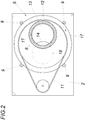
- the pneumatic tube station shown has a housing 1 with a housing base 2 and with a housing cover 3, which is connected to a receiving tube 4.
- a sleeve receptacle 5 is rotatably mounted about a vertical axis of rotation 6, which comprises a lower and an upper annular disk 7 and a receiving tube 8 connecting this annular disk 7.
- Guide bearings 9, which are mounted on the housing base 2 and on the housing cover 3, between which the annular disks 7 are rotatably mounted at an axial distance from the housing base 2 or the housing cover 3 are used to support the bushing receptacle 5.
- a geared motor 10 which drives a toothed belt drive 11 for the lower annular disk 7, is used to drive the sleeve receptacle 5.
- the receiving tube 8 of the sleeve receptacle 5 is arranged such that a pneumatic tube bush 12 received by the receiving tube 8 positions the sleeve cover 13 in a predetermined rotational position such that its bearing axes 14 coincide with the axis of rotation 6 of the sleeve receptacle 5.
- the pneumatic tube 12 conveyed into the receiving tube 8 via the receiving tube 4 must be rotated into the required rotational position within the receiving tube 8.
- a coaxial turntable 15 for connecting the receiving tube 4 is provided in the housing base 2, which is driven by a geared motor 16 and rotates the pneumatic tube bushing 8 resting on the turntable 15 into the desired rotational position monitored by a sensor or a rotary stop, in which the bearing axes 14 of the sleeve cover 13 coincide with the axis of rotation 6 of the sleeve receptacle 5.
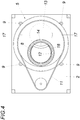
- the bush covers 13 need only be held in place by housing-fixed stop guides 17 during the rotation of the bush receptacle 5 in order to remove the pneumatic tube bushings 8 during the rotation of the bush receptacle 5 Fig. 1 and 2nd shown receiving position in the unloading position after the Fig. 3 and 4th to open.
- the sleeve cover 13 When the sleeve cover 13 is opened, the cargo exits through the sleeve opening on the housing base 2 and is along the housing base 2 to an outlet opening which determines the unloading position 18 promoted in the housing base 2 through which it falls out of the housing 1.
- the discharge of the cargo from the pneumatic tube bushing 12 can be supported by a corresponding tool which is inserted from above through the through hole 19 into the pneumatic tube bushing 12. Cleaning of the pneumatic tube can 12 is also possible through this passage opening 19, wherein the tool for ejecting the cargo can also advantageously be designed for cleaning the pneumatic tube sleeve.
- the sleeve receptacle 5 After unloading the pneumatic tube rifle, the sleeve receptacle 5 is rotated back into the receiving position, the sleeve covers 13 being closed because the pneumatic tube sleeve 12 moves into the closed position relative to the sleeve caps 13 held between the stop guides 17.
- the closed pneumatic tube bushing 12 can then be extended through the receiving tube 4 as a transmitting tube from the pneumatic tube station.
- seals 20 are composed of two ring parts 21 and 22, as is the case in particular Fig. 6 can be removed. While the ring part 21 is connected to the respective ring disk 7 on the side facing the housing base 2 or the housing cover 3, the ring part 22 is assigned to the housing 1 on the floor or ceiling side.
Landscapes
- Physics & Mathematics (AREA)
- Engineering & Computer Science (AREA)
- Fluid Mechanics (AREA)
- Mechanical Engineering (AREA)
- Pressure Vessels And Lids Thereof (AREA)
Description
- Die Erfindung bezieht sich auf eine Rohrpoststation für Rohrpostbüchsen, deren Deckel um eine zur Büchsenachse parallele Lagerachse verschwenkbar sind, mit einem an eine Empfangsleitung und eine Sendeleitung angeschlossenen Gehäuse (1) und mit einer innerhalb des Gehäuses um eine vertikale Drehachse zwischen einer Empfangsstellung und einer Entladestellung verschwenkbaren Büchsenaufnahme, die die zur Drehachse achsparallelen Rohrpostbüchsen in einer vorgegebenen Drehlage hält, und mit dem Gehäuse zugeordneten Anschlagführungen für die Büchsendeckel.
- Um Rohrpostbüchsen mit um achsparallele Lagerachsen verschwenkbaren Deckeln vorteilhaft entladen zu können, sind Rohrpoststationen bekannt (
AT 515 548 B1 - Der Erfindung liegt somit die Aufgabe zugrunde, eine Rohrpoststation mit einfachen konstruktiven Mitteln so auszugestalten, dass trotz eines geringen Platzbedarfs gute Voraussetzungen insbesondere für ein Entladen der empfangenen Rohrpostbüchsen geschaffen werden.
- Ausgehend von einer Rohrpoststation der eingangs geschilderten Art löst die Erfindung die gestellte Aufgabe dadurch, dass in der vorgegebenen Drehlage der Rohrpostbüchsen die Lagerachsen der Büchsendeckel mit der Drehachse der Büchsenaufnahme zusammenfallen und dass die Empfangsleitung als Sendeleitung einsetzbar ist.
- Da die Drehachse der Büchsenaufnahme mit den Lagerachsen der Büchsendeckel in der Solldrehlage der Rohrpostbüchsen zusammenfällt, kann die für die Verlagerung der Büchsenaufnahme benötigte Grundfläche im Wesentlichen auf eine Kreisfläche mit einem dem Büchsendurchmesser entsprechenden Radius beschränkt werden, was eine besonders gedrängte Bauweise mit dem Vorteil mit sich bringt, dass zum Öffnen und Schließen die Büchsendeckel nicht gegenüber dem Gehäuse verlagert werden und daher lediglich durch entsprechende Führungsanschläge in Ihrer Lage festzuhalten sind, sodass sich hinsichtlich des Öffnens und Schließens der Rohrpostbüchsen besonders einfache Konstruktionsverhältnisse ergeben. Die Drehung der Büchsenaufnahme um die Lagerachsen der Büchsendeckel zwischen einer Empfangsstellung und einer Entladestellung setzt voraus, dass das an das Gehäuse angeschlossene Empfangsrohr auch als Senderohr eingesetzt werden kann, was eine zusätzliche Konstruktionsvereinfachung erlaubt. Zum Entladen einer in der Rohrpoststation empfangenen Rohrpostbüchse muss zunächst sichergestellt werden, dass die Rohrpostbüchse in der Büchsenaufnahme so um ihre Achse gedreht wird, dass die Lagerachsen der Büchsendeckel mit der Drehachse der Büchsenaufnahme zusammenfallen. Zu diesem Zweck weist die Büchsenaufnahme einen antreibbaren Drehteller auf, auf dem die Rohrpostbuchse aufruht. Mit Hilfe des Drehtellers wird die Rohrpostbüchse in die gewünschte Drehlage gedreht, die entweder durch einen entsprechenden Sensor für die Drehlage der Rohrpostbüchse oder einen mit der Rohrpostbüchse zusammenwirkenden Drehanschlag bestimmt wird. Stimmen die Lagerachsen der Büchsendeckel mit der Drehachse der Büchsenaufnahme überein, so kann die Büchsenaufnahme in die Entladestellung gedreht werden, in der sich der Büchsenkörper über eine Austragsöffnung im Gehäuseboden befindet. Da bei dieser Drehverlagerung der Rohrpostbüchsen von der Empfangsstellung zur Entladestellung die Büchsendeckel durch die gehäusefesten Anschlagführungen gegen eine Drehmitnahme festgehalten werden, wird die Rohrpostbüchse geöffnet, sodass in der Entladestellung der Büchseninhalt durch die bodenseitige Austragsöffnung fällt. Nach der Entladung der Rohrpostbüchse wird die Büchsenaufnahme in die Empfangsstellung unter einem Schließen der Büchsendeckel zurückgedreht, sodass die Rohrpostbüchse die Rohrpoststation über das nunmehr als Senderohr dienende Empfangsrohr wieder verlassen kann.
- Besonders einfache Konstruktionsverhältnisse ergeben sich, wenn die Büchsenaufnahme eine mit axialem Abstand oberhalb des Gehäusebodens gelagerte, antreibbare Ringscheibe zur Halterung eines Aufnahmerohrs für die Rohrpostbüchsen umfasst. Diese außen zu lagernde Ringscheibe kann vorteilhaft beispielsweise über einen Zahnriementrieb angetrieben werden und nimmt die Rohrpostbüchse in einem Aufnahmerohr auf, in dem die Rohrpostbüchse sicher gehalten wird. Der axiale Abstand der Ringscheibe vom Gehäuseboden ist für die Aufnahme des Büchsendeckels bei der Drehung der Ringscheibe erforderlich. Obwohl für die grundsätzliche Funktion das Aufnahmerohr lediglich in einer Ringscheibe gelagert zu werden braucht, ergeben sich günstige Konstruktionsbedingungen, wenn das Aufnahmerohr zwischen der bodenseitigen Ringscheibe und einer deckenseitigen, mit axialem Abstand unterhalb der Gehäusedecke angeordneten Ringscheibe gehalten wird, die nach oben hin Raum für das Öffnen des oberen Gehäusedeckels frei lässt. Das Öffnen sowohl des unteren als auch des oberen Gehäusedeckels stellt eine Voraussetzung für ein Reinigen der Rohrpostbüchse in der Entladestellung dar, weil beispielsweise eine Reinigungsbürste von oben durch das Gehäuse in die beidseitig offene Rohrpostbüchse eingeführt werden kann. Die oben offene Rohrpostbüchse ermöglicht aber auch ein Ausstoßen des Büchseninhalts mithilfe eines zu diesem Zweck von oben in die Rohrpostbüchse eingeführten Werkzeugs.
- Um wahlweise die beiden Büchsendeckel einer Rohrpostbüchse öffnen und schließen zu können, können die dem Gehäuseboden und der Gehäusedecke zugeordneten Anschlagführungen für die Büchsendeckel zwischen einer Gebrauchsstellung und einer Ruhestellung verlagerbar sein. In der aus der Gebrauchsstellung zurückgezogenen Ruhestellung werden die Büchsendeckel durch diese Führungsanschläge nicht gegenüber der sich mit der Büchsenaufnahme drehenden Rohrpostbüchse zurückgehalten und bleiben daher geschlossen. Dies ist insbesondere für die unteren Büchsendeckel dann erforderlich, wenn die Rohrpoststation auch zum Laden der Rohrpostbüchsen eingesetzt werden soll, weil in diesem Fall die Rohrpostbüchse zum Befüllen unten geschlossen sein muss, während das Ladegut von oben in die Rohrpostbüchse eingebracht wird.
- Um die in der Rohrpoststation zu empfangende Rohrpostbüchse gedämpft abbremsen zu können, kann innerhalb des Aufnahmerohrs der Büchsenaufnahme ein Luftpolster aufgebaut werden. Da das Aufnahmerohr jedoch mit axialem Abstand oberhalb des Gehäusebodens endet, ist für eine die Ringöffnung umschließende Dichtung zwischen der Ringscheibe und dem Gehäuseboden zu sorgen. Diese Dichtung kann sich vorteilhaft aus zwei Ringteilen zusammensetzen, von denen ein sich höchstens über einen halben Umfangsabschnitt erstreckender Ringteil der Ringscheibe zugeordnet ist und der andere die Dichtung zu einem geschlossenen Ring ergänzende, dem Gehäuse zugehörige Ringteil zumindest einen von der Ringöffnung wegschwenkbaren Abschnitt aufweist oder bildet. Durch diese Teilung der Dichtung beeinträchtigt diese Dichtung die Betätigung der Büchsendeckel während der Büchsenverlagerung nicht. Der der Ringscheibe zugehörige Ringteil wird ja mit der Rohrpostbüchse vom festgehaltenen Büchsendeckel weggedreht. Der dem Gehäuse zugehörige Ringteil würde allerdings der Drehbewegung des Ringteils auf der Ringscheibe im Wege stehen, wenn dieser Ringteil des Gehäuses nicht schwenkbar gelagert wäre oder einen entsprechend ausschwenkbaren Abschnitt hätte.
- Da ein Luftpolster im Aufnahmerohr der Büchsenaufnahme im Allgemeinen nicht für eine ausreichend gedämpfte Abbremsung der Rohrpostbüchse sorgen kann, empfiehlt es sich, diesen Luftpolster in das an das Gehäuse anschließende Empfangsrohr hinein zu verlängern, was eine zusätzliche Abdichtung des Spalts zwischen der oberen Ringscheibe der Büchsenaufnahme und der Gehäusedecke erfordert. Diese Dichtung wird in gleicher Weise aus zwei Ringteilen wie die Dichtung im Bereich der unteren Ringscheibe ausgeführt.
- In der Zeichnung ist der Erfindungsgegenstand beispielsweise dargestellt. Es zeigen
- Fig. 1
- eine erfindungsgemäße Rohrpoststation in der Empfangsstellung in einem schematischen Vertikalschnitt,
- Fig. 2
- diese Rohrpoststation in einem Schnitt nach der Linie II-II der
Fig. 1 , - Fig. 3
- eine der
Fig. 1 entsprechende Darstellung der erfindungsgemäßen Rohrpoststation, jedoch in der Entladestellung, - Fig. 4
- einen Schnitt nach der Linie IV-IV der
Fig. 3 , - Fig. 5
- eine Ausführungsvariante einer erfindungsgemäßen Rohrpoststation ausschnittsweise im Bereich der unteren Ringscheibe in einem Vertikalschnitt und
- Fig. 6
- eine zum Teil aufgerissene Draufsicht auf die untere Ringscheibe gemäß der
Fig. 5 . - Die dargestellte Rohrpoststation weist ein Gehäuse 1 mit einem Gehäuseboden 2 und mit einer Gehäusedecke 3 auf, die an ein Empfangsrohr 4 angeschlossen ist. Innerhalb des Gehäuses 1 ist eine Büchsenaufnahme 5 um eine vertikale Drehachse 6 drehbar gelagert, die eine untere und eine obere Ringscheibe 7 und ein diese Ringscheibe 7 verbindendes Aufnahmerohr 8 umfasst. Zur Lagerung der Büchsenaufnahme 5 dienen am Gehäuseboden 2 und an der Gehäusedecke 3 gelagerte Führungsrollen 9, zwischen denen die Ringscheiben 7 mit axialem Abstand vom Gehäuseboden 2 bzw. der Gehäusedecke 3 drehbar gelagert sind. Zum Antrieb der Büchsenaufnahme 5 dient ein Getriebemotor 10, der einen Zahnriementrieb 11 für die untere Ringscheibe 7 antreibt.
- Wie insbesondere der
Fig. 1 entnommen werden kann, ist das Aufnahmerohr 8 der Büchsenaufnahme 5 so angeordnet, dass eine vom Aufnahmerohr 8 aufgenommene Rohrpostbüchse 12 in einer vorgegebenen Drehlage die Büchsendeckel 13 so positioniert, dass deren Lagerachsen 14 mit der Drehachse 6 der Büchsenaufnahme 5 zusammenfallen. Um diese Drehlage der Rohrpostbüchse 12 sicherzustellen, muss die über das Empfangsrohr 4 in das Aufnahmerohr 8 geförderte Rohrpostbüchse 12 innerhalb des Aufnahmerohrs 8 in die geforderte Drehlage gedreht werden. Zu diesem Zweck ist im Gehäuseboden 2 ein zum Anschluss des Empfangsrohrs 4 koaxialer Drehteller 15 vorgesehen, der über einen Getriebemotor 16 angetrieben wird und die auf dem Drehteller 15 aufruhende Rohrpostbüchse 8 in die von einem Sensor oder einem Drehanschlag überwachte Solldrehlage dreht, in der die Lagerachsen 14 der Büchsendeckel 13 mit der Drehachse 6 der Büchsenaufnahme 5 zusammenfallen. - Aufgrund dieser Maßnahme brauchen die Büchsendeckel 13 während der Drehung der Büchsenaufnahme 5 lediglich durch gehäusefeste Anschlagführungen 17 festgehalten zu werden, um die Rohrpostbüchsen 8 während der Drehung der Büchsenaufnahme 5 aus der in den
Fig. 1 und2 dargestellten Empfangsstellung in die Entladestellung nach denFig. 3 und4 zu öffnen. Beim Öffnen der Büchsendeckel 13 tritt das Ladegut durch die Büchsenöffnung auf den Gehäuseboden 2 aus und wird entlang des Gehäusebodens 2 bis zu einer die Entladestellung bestimmenden Austrittsöffnung 18 im Gehäuseboden 2 gefördert, durch die sie aus dem Gehäuse 1 fällt. Da eine zur Austrittsöffnung 18 korrespondierende Durchtrittsöffnung 19 in der Gehäusedecke 3 vorgesehen ist, kann das Austragen des Ladeguts aus der Rohrpostbüchse 12 durch ein entsprechendes Werkzeug unterstützt werden, das von oben durch die Durchtrittsöffnung 19 in die Rohrpostbüchse 12 eingeführt wird. Durch diese Durchtrittsöffnung 19 ist auch eine Reinigung der Rohrpostbüchse 12 möglich, wobei vorteilhaft das Werkzeug zum Ausstoßen des Ladeguts auch zum Reinigen der Rohrpostbüchse ausgebildet sein kann. - Nach dem Entladen der Rohrpostbüchse wird die Büchsenaufnahme 5 wieder in die Empfangsstellung zurückgedreht, wobei die Büchsendeckel 13 geschlossen werden, weil sich die Rohrpostbüchse 12 gegenüber den zwischen den Anschlagführungen 17 festgehalten Büchsendeckeln 13 in die Schließstellung bewegt. Die geschlossene Rohrpostbüchse 12 kann dann durch das Empfangsrohr 4 als Senderohr aus der Rohrpoststation ausgefahren werden.
- Wie den
Fig. 5 und 6 entnommen werden kann, kann zum Aufbau eines Luftpolsters innerhalb des Aufnahmerohrs 8 der Büchsenaufnahme 5 und im Anschluss daran im Empfangsrohr 4 das Aufnahmerohr 8 in der Empfangsstellung der Büchsenaufnahme 5 gegenüber dem Gehäuse 1 durch Dichtungen 20 abgedichtet werden. Diese Dichtungen 20 sind aus zwei Ringteilen 21 und 22 zusammengesetzt, wie dies insbesondere derFig. 6 entnommen werden kann. Während der Ringteil 21 jeweils auf der dem Gehäuseboden 2 bzw. der Gehäusedecke 3 zugekehrten Seite mit der jeweiligen Ringscheibe 7 verbunden ist, ist der Ringteil 22 dem Gehäuse 1 boden- bzw. deckenseitig zugeordnet. Wird die Büchsenaufnahme 5 aus der Empfangsstellung, in der sich die Ringteile 21 und 22 zur geschlossenen Dichtung 20 ergänzen, um die Drehachse 6 in die in derFig. 6 strichpunktiert angedeutete Entladestellung gedreht, so dreht sich der Ringteil 21 auf den Ringscheiben 7 mit, was nur möglich ist, wenn zumindest ein Abschnitt 23 des dem Gehäuse 1 zugehörigen Ringteils 21 um eine Achse 24 ausschwenkbar gelagert ist. Durch diese Verschwenkbarkeit des Abschnitts 23 des Ringteils 22 wird die Bewegungsbahn für den mit der Ringscheibe 7 verbundenen Ringteil 21 freigegeben. Mit dem Rückdrehen der Büchsenaufnahme 5 aus der Entladestellung in die Empfangsstellung kehren der Ringteil 21 und der verschwenkbare Abschnitt 23 des Ringteils 22 wieder in ihre Ausgangslage zurück, was für den verschwenkbaren Abschnitt 23 eine entsprechende Federbelastung erfordert.
Claims (5)
- Rohrpoststation für Rohrpostbüchsen (12), deren Deckel (13) um eine zur Büchsenachse parallele Lagerachse (14) verschwenkbar sind, mit einem an eine Empfangsleitung (4) und eine Sendeleitung angeschlossenen Gehäuse (1) und mit einer innerhalb des Gehäuses (1) um eine vertikale Drehachse (6) zwischen einer Empfangsstellung und einer Entladestellung verschwenkbaren Büchsenaufnahme (5), die die zur Drehachse (6) achsparallelen Rohrpostbüchsen (12) in einer vorgegebenen Drehlage hält, und mit dem Gehäuse (1) zugeordneten Anschlagführungen (17) für die Büchsendeckel (13), dadurch gekennzeichnet, dass in der vorgegebenen Drehlage der Rohrpostbüchsen (12) die Lagerachsen (14) der Büchsendeckel (13) mit der Drehachse (6) der Büchsenaufnahme (5) zusammenfallen und dass die Empfangsleitung (4) als Sendeleitung einsetzbar ist.
- Rohrpoststation nach Anspruch 1, dadurch gekennzeichnet, dass die Büchsenaufnahme (5) eine mit axialem Abstand oberhalb des Gehäusebodens (2) gelagerte, antreibbare Ringscheibe (7) zur Halterung eines Aufnahmerohrs (8) für die Rohrpostbüchsen (12) umfasst.
- Rohrpoststation nach Anspruch 2, dadurch gekennzeichnet, dass das Aufnahmerohr (8) der Büchsenaufnahme (5) zwischen der bodenseitigen Ringscheibe (7) und einer deckenseitigen, mit axialem Abstand unterhalb der Gehäusedecke (3) angeordneten Ringscheibe (7) gehalten ist.
- Rohrpoststation nach Anspruch 2 oder 3, dadurch gekennzeichnet, dass die dem Gehäuseboden (2) und der Gehäusedecke (3) zugeordneten Anschlagführungen (17) für die Büchsendeckel (13) zwischen einer Gebrauchsstellung und einer Ruhestellung verlagerbar sind.
- Rohrpoststation nach einem der Ansprüche 2 bis 4, dadurch gekennzeichnet, dass zwischen dem Gehäuse (1) und zumindest der bodenseitigen Ringscheibe (7) eine deren Ringöffnung umschließende Dichtung (20) aus zwei Ringteile (21, 22) vorgesehen ist, von denen ein sich höchstens über einen halben Umfangsabschnitt erstreckender Ringteil (21) der Ringscheibe (7) zugeordnet ist und der andere die Dichtung (20) zu einem geschlossenen Ring ergänzende, dem Gehäuse (1) zugehörige Ringteil (22) zumindest einen von der Ringöffnung wegschwenkbaren Abschnitt (23) aufweist oder bildet.
Applications Claiming Priority (2)
| Application Number | Priority Date | Filing Date | Title |
|---|---|---|---|
| ATA50986/2015A AT517702B1 (de) | 2015-11-19 | 2015-11-19 | Rohrpoststation |
| PCT/AT2016/050258 WO2017083892A1 (de) | 2015-11-19 | 2016-09-27 | Rohrpoststation |
Publications (2)
| Publication Number | Publication Date |
|---|---|
| EP3377429A1 EP3377429A1 (de) | 2018-09-26 |
| EP3377429B1 true EP3377429B1 (de) | 2020-07-29 |
Family
ID=57394296
Family Applications (1)
| Application Number | Title | Priority Date | Filing Date |
|---|---|---|---|
| EP16801121.1A Active EP3377429B1 (de) | 2015-11-19 | 2016-09-27 | Rohrpoststation |
Country Status (3)
| Country | Link |
|---|---|
| EP (1) | EP3377429B1 (de) |
| AT (1) | AT517702B1 (de) |
| WO (1) | WO2017083892A1 (de) |
Families Citing this family (1)
| Publication number | Priority date | Publication date | Assignee | Title |
|---|---|---|---|---|
| CN110723545A (zh) * | 2019-10-18 | 2020-01-24 | 河南智航之匠后勤管理有限公司 | 一种智能标本传输装置 |
Family Cites Families (4)
| Publication number | Priority date | Publication date | Assignee | Title |
|---|---|---|---|---|
| JP2007045599A (ja) * | 2005-08-11 | 2007-02-22 | Siemens Kk | 気送管設備 |
| FR2939114B1 (fr) * | 2008-12-01 | 2013-07-19 | Snef Cote D Azur | Station et methode de transfert pour cartouche pneumatique |
| AT513627B1 (de) * | 2013-02-22 | 2014-06-15 | Hanazeder Erwin | Rohrpoststation |
| AT515548B1 (de) * | 2014-07-31 | 2015-10-15 | Hanazeder Erwin | Rohrpoststation zum Entladen von Rohrpostbüchsen |
-
2015
- 2015-11-19 AT ATA50986/2015A patent/AT517702B1/de active
-
2016
- 2016-09-27 WO PCT/AT2016/050258 patent/WO2017083892A1/de not_active Ceased
- 2016-09-27 EP EP16801121.1A patent/EP3377429B1/de active Active
Non-Patent Citations (1)
| Title |
|---|
| None * |
Also Published As
| Publication number | Publication date |
|---|---|
| EP3377429A1 (de) | 2018-09-26 |
| AT517702B1 (de) | 2017-04-15 |
| WO2017083892A1 (de) | 2017-05-26 |
| AT517702A4 (de) | 2017-04-15 |
Similar Documents
| Publication | Publication Date | Title |
|---|---|---|
| DE4200701B4 (de) | Maschine zum Dosieren pulverförmiger Pharmazeutika | |
| DE10329959A1 (de) | Halter für einen Getränkebehälter | |
| DE102016201852A1 (de) | Werkstück-Abgabevorrichtung für eine Werkzeugmaschine | |
| DE2360201A1 (de) | Vorrichtung zum entleeren von wegwerfbehaeltnissen, insbesondere zaehlflaeschchen fuer radioaktive fluessigkeiten | |
| DE3734560C2 (de) | ||
| DE102009018528A1 (de) | Spender zur Ausgabe eines Materials aus einem Behälter | |
| DE102015111533B4 (de) | Rohrpoststation zum Entladen von Rohrpostbüchsen | |
| DE4444117C1 (de) | Schubzentrifuge | |
| DE102007041597B4 (de) | Befüllsystem zum dosierten Ausbringen eines Schmierstoffs | |
| DE60123084T2 (de) | Flexibler Behälter zum Gebrauch in einem Flüssigkeisspender | |
| DE10206837A1 (de) | Fördersystem | |
| EP2356043A1 (de) | Magazin zur lagerung von twist-locks | |
| AT517702B1 (de) | Rohrpoststation | |
| EP0064949A1 (de) | Behälterverschluss für aufsetzbare Abzapfvorrichtungen | |
| DE102012005461A1 (de) | Füllelement sowie Füllmaschine | |
| AT524191B1 (de) | Hülse und rohrpoststation | |
| DE2107335C3 (de) | Belade- und Entladestation für pneumatische Rohrförderanlagen mit Transportbehältern | |
| DE20316541U1 (de) | Flaschen- oder Becherhalter für ein Kraftfahrzeug | |
| DE202008010576U1 (de) | Maschinelle Vorrichtung zur Montage und/oder zur Demontage einer Laserdüse sowie Laserbearbeitungsmaschine mit einer derartigen maschinellen Vorrichtung | |
| DE4335949C2 (de) | Einrichtung zum Ausstoßen von Material aus einem Silo oder einem entsprechenden Lagerbehälter | |
| EP0697354A1 (de) | Hülse für eine Rohrpostanlage sowie Laderohr für eine Rohrpoststation | |
| DE2348591A1 (de) | Zufuehrtrichter fuer zigarettenzaehl-, -transport- und verpackungsmaschinen | |
| DE2702343C3 (de) | Regalförderzeug | |
| DE102012111748A1 (de) | Füllmaschine | |
| DE2230458C3 (de) | Zylindrischer Silo für gekörntes und pulverförmiges Material |
Legal Events
| Date | Code | Title | Description |
|---|---|---|---|
| STAA | Information on the status of an ep patent application or granted ep patent |
Free format text: STATUS: UNKNOWN |
|
| STAA | Information on the status of an ep patent application or granted ep patent |
Free format text: STATUS: THE INTERNATIONAL PUBLICATION HAS BEEN MADE |
|
| PUAI | Public reference made under article 153(3) epc to a published international application that has entered the european phase |
Free format text: ORIGINAL CODE: 0009012 |
|
| STAA | Information on the status of an ep patent application or granted ep patent |
Free format text: STATUS: REQUEST FOR EXAMINATION WAS MADE |
|
| 17P | Request for examination filed |
Effective date: 20180306 |
|
| AK | Designated contracting states |
Kind code of ref document: A1 Designated state(s): AL AT BE BG CH CY CZ DE DK EE ES FI FR GB GR HR HU IE IS IT LI LT LU LV MC MK MT NL NO PL PT RO RS SE SI SK SM TR |
|
| AX | Request for extension of the european patent |
Extension state: BA ME |
|
| DAV | Request for validation of the european patent (deleted) | ||
| DAX | Request for extension of the european patent (deleted) | ||
| GRAP | Despatch of communication of intention to grant a patent |
Free format text: ORIGINAL CODE: EPIDOSNIGR1 |
|
| STAA | Information on the status of an ep patent application or granted ep patent |
Free format text: STATUS: GRANT OF PATENT IS INTENDED |
|
| INTG | Intention to grant announced |
Effective date: 20200430 |
|
| GRAS | Grant fee paid |
Free format text: ORIGINAL CODE: EPIDOSNIGR3 |
|
| GRAA | (expected) grant |
Free format text: ORIGINAL CODE: 0009210 |
|
| STAA | Information on the status of an ep patent application or granted ep patent |
Free format text: STATUS: THE PATENT HAS BEEN GRANTED |
|
| AK | Designated contracting states |
Kind code of ref document: B1 Designated state(s): AL AT BE BG CH CY CZ DE DK EE ES FI FR GB GR HR HU IE IS IT LI LT LU LV MC MK MT NL NO PL PT RO RS SE SI SK SM TR |
|
| REG | Reference to a national code |
Ref country code: CH Ref legal event code: EP |
|
| REG | Reference to a national code |
Ref country code: AT Ref legal event code: REF Ref document number: 1295542 Country of ref document: AT Kind code of ref document: T Effective date: 20200815 |
|
| REG | Reference to a national code |
Ref country code: IE Ref legal event code: FG4D Free format text: LANGUAGE OF EP DOCUMENT: GERMAN |
|
| REG | Reference to a national code |
Ref country code: DE Ref legal event code: R096 Ref document number: 502016010681 Country of ref document: DE |
|
| REG | Reference to a national code |
Ref country code: SE Ref legal event code: TRGR |
|
| REG | Reference to a national code |
Ref country code: LT Ref legal event code: MG4D |
|
| REG | Reference to a national code |
Ref country code: NL Ref legal event code: MP Effective date: 20200729 |
|
| PG25 | Lapsed in a contracting state [announced via postgrant information from national office to epo] |
Ref country code: PT Free format text: LAPSE BECAUSE OF FAILURE TO SUBMIT A TRANSLATION OF THE DESCRIPTION OR TO PAY THE FEE WITHIN THE PRESCRIBED TIME-LIMIT Effective date: 20201130 Ref country code: NO Free format text: LAPSE BECAUSE OF FAILURE TO SUBMIT A TRANSLATION OF THE DESCRIPTION OR TO PAY THE FEE WITHIN THE PRESCRIBED TIME-LIMIT Effective date: 20201029 Ref country code: FI Free format text: LAPSE BECAUSE OF FAILURE TO SUBMIT A TRANSLATION OF THE DESCRIPTION OR TO PAY THE FEE WITHIN THE PRESCRIBED TIME-LIMIT Effective date: 20200729 Ref country code: HR Free format text: LAPSE BECAUSE OF FAILURE TO SUBMIT A TRANSLATION OF THE DESCRIPTION OR TO PAY THE FEE WITHIN THE PRESCRIBED TIME-LIMIT Effective date: 20200729 Ref country code: BG Free format text: LAPSE BECAUSE OF FAILURE TO SUBMIT A TRANSLATION OF THE DESCRIPTION OR TO PAY THE FEE WITHIN THE PRESCRIBED TIME-LIMIT Effective date: 20201029 Ref country code: GR Free format text: LAPSE BECAUSE OF FAILURE TO SUBMIT A TRANSLATION OF THE DESCRIPTION OR TO PAY THE FEE WITHIN THE PRESCRIBED TIME-LIMIT Effective date: 20201030 Ref country code: ES Free format text: LAPSE BECAUSE OF FAILURE TO SUBMIT A TRANSLATION OF THE DESCRIPTION OR TO PAY THE FEE WITHIN THE PRESCRIBED TIME-LIMIT Effective date: 20200729 Ref country code: LT Free format text: LAPSE BECAUSE OF FAILURE TO SUBMIT A TRANSLATION OF THE DESCRIPTION OR TO PAY THE FEE WITHIN THE PRESCRIBED TIME-LIMIT Effective date: 20200729 |
|
| PG25 | Lapsed in a contracting state [announced via postgrant information from national office to epo] |
Ref country code: PL Free format text: LAPSE BECAUSE OF FAILURE TO SUBMIT A TRANSLATION OF THE DESCRIPTION OR TO PAY THE FEE WITHIN THE PRESCRIBED TIME-LIMIT Effective date: 20200729 Ref country code: RS Free format text: LAPSE BECAUSE OF FAILURE TO SUBMIT A TRANSLATION OF THE DESCRIPTION OR TO PAY THE FEE WITHIN THE PRESCRIBED TIME-LIMIT Effective date: 20200729 Ref country code: LV Free format text: LAPSE BECAUSE OF FAILURE TO SUBMIT A TRANSLATION OF THE DESCRIPTION OR TO PAY THE FEE WITHIN THE PRESCRIBED TIME-LIMIT Effective date: 20200729 Ref country code: IS Free format text: LAPSE BECAUSE OF FAILURE TO SUBMIT A TRANSLATION OF THE DESCRIPTION OR TO PAY THE FEE WITHIN THE PRESCRIBED TIME-LIMIT Effective date: 20201129 |
|
| PG25 | Lapsed in a contracting state [announced via postgrant information from national office to epo] |
Ref country code: NL Free format text: LAPSE BECAUSE OF FAILURE TO SUBMIT A TRANSLATION OF THE DESCRIPTION OR TO PAY THE FEE WITHIN THE PRESCRIBED TIME-LIMIT Effective date: 20200729 |
|
| PG25 | Lapsed in a contracting state [announced via postgrant information from national office to epo] |
Ref country code: IT Free format text: LAPSE BECAUSE OF FAILURE TO SUBMIT A TRANSLATION OF THE DESCRIPTION OR TO PAY THE FEE WITHIN THE PRESCRIBED TIME-LIMIT Effective date: 20200729 Ref country code: EE Free format text: LAPSE BECAUSE OF FAILURE TO SUBMIT A TRANSLATION OF THE DESCRIPTION OR TO PAY THE FEE WITHIN THE PRESCRIBED TIME-LIMIT Effective date: 20200729 Ref country code: SM Free format text: LAPSE BECAUSE OF FAILURE TO SUBMIT A TRANSLATION OF THE DESCRIPTION OR TO PAY THE FEE WITHIN THE PRESCRIBED TIME-LIMIT Effective date: 20200729 Ref country code: CZ Free format text: LAPSE BECAUSE OF FAILURE TO SUBMIT A TRANSLATION OF THE DESCRIPTION OR TO PAY THE FEE WITHIN THE PRESCRIBED TIME-LIMIT Effective date: 20200729 Ref country code: DK Free format text: LAPSE BECAUSE OF FAILURE TO SUBMIT A TRANSLATION OF THE DESCRIPTION OR TO PAY THE FEE WITHIN THE PRESCRIBED TIME-LIMIT Effective date: 20200729 Ref country code: RO Free format text: LAPSE BECAUSE OF FAILURE TO SUBMIT A TRANSLATION OF THE DESCRIPTION OR TO PAY THE FEE WITHIN THE PRESCRIBED TIME-LIMIT Effective date: 20200729 |
|
| REG | Reference to a national code |
Ref country code: CH Ref legal event code: PL Ref country code: DE Ref legal event code: R097 Ref document number: 502016010681 Country of ref document: DE |
|
| PG25 | Lapsed in a contracting state [announced via postgrant information from national office to epo] |
Ref country code: AL Free format text: LAPSE BECAUSE OF FAILURE TO SUBMIT A TRANSLATION OF THE DESCRIPTION OR TO PAY THE FEE WITHIN THE PRESCRIBED TIME-LIMIT Effective date: 20200729 |
|
| PLBE | No opposition filed within time limit |
Free format text: ORIGINAL CODE: 0009261 |
|
| STAA | Information on the status of an ep patent application or granted ep patent |
Free format text: STATUS: NO OPPOSITION FILED WITHIN TIME LIMIT |
|
| REG | Reference to a national code |
Ref country code: BE Ref legal event code: MM Effective date: 20200930 |
|
| GBPC | Gb: european patent ceased through non-payment of renewal fee |
Effective date: 20201029 |
|
| PG25 | Lapsed in a contracting state [announced via postgrant information from national office to epo] |
Ref country code: SK Free format text: LAPSE BECAUSE OF FAILURE TO SUBMIT A TRANSLATION OF THE DESCRIPTION OR TO PAY THE FEE WITHIN THE PRESCRIBED TIME-LIMIT Effective date: 20200729 Ref country code: LU Free format text: LAPSE BECAUSE OF NON-PAYMENT OF DUE FEES Effective date: 20200927 |
|
| 26N | No opposition filed |
Effective date: 20210430 |
|
| PG25 | Lapsed in a contracting state [announced via postgrant information from national office to epo] |
Ref country code: IE Free format text: LAPSE BECAUSE OF NON-PAYMENT OF DUE FEES Effective date: 20200927 Ref country code: GB Free format text: LAPSE BECAUSE OF NON-PAYMENT OF DUE FEES Effective date: 20201029 Ref country code: SI Free format text: LAPSE BECAUSE OF FAILURE TO SUBMIT A TRANSLATION OF THE DESCRIPTION OR TO PAY THE FEE WITHIN THE PRESCRIBED TIME-LIMIT Effective date: 20200729 Ref country code: BE Free format text: LAPSE BECAUSE OF NON-PAYMENT OF DUE FEES Effective date: 20200930 |
|
| PGFP | Annual fee paid to national office [announced via postgrant information from national office to epo] |
Ref country code: CH Payment date: 20210610 Year of fee payment: 5 |
|
| REG | Reference to a national code |
Ref country code: DE Ref legal event code: R081 Ref document number: 502016010681 Country of ref document: DE Owner name: HANAZEDER ELECTRONIC GMBH, AT Free format text: FORMER OWNER: HANAZEDER, ERWIN, NEUHOFEN, AT |
|
| REG | Reference to a national code |
Ref country code: CH Ref legal event code: PL |
|
| PG25 | Lapsed in a contracting state [announced via postgrant information from national office to epo] |
Ref country code: TR Free format text: LAPSE BECAUSE OF FAILURE TO SUBMIT A TRANSLATION OF THE DESCRIPTION OR TO PAY THE FEE WITHIN THE PRESCRIBED TIME-LIMIT Effective date: 20200729 Ref country code: MT Free format text: LAPSE BECAUSE OF FAILURE TO SUBMIT A TRANSLATION OF THE DESCRIPTION OR TO PAY THE FEE WITHIN THE PRESCRIBED TIME-LIMIT Effective date: 20200729 Ref country code: CY Free format text: LAPSE BECAUSE OF FAILURE TO SUBMIT A TRANSLATION OF THE DESCRIPTION OR TO PAY THE FEE WITHIN THE PRESCRIBED TIME-LIMIT Effective date: 20200729 |
|
| PG25 | Lapsed in a contracting state [announced via postgrant information from national office to epo] |
Ref country code: MK Free format text: LAPSE BECAUSE OF FAILURE TO SUBMIT A TRANSLATION OF THE DESCRIPTION OR TO PAY THE FEE WITHIN THE PRESCRIBED TIME-LIMIT Effective date: 20200729 Ref country code: MC Free format text: LAPSE BECAUSE OF FAILURE TO SUBMIT A TRANSLATION OF THE DESCRIPTION OR TO PAY THE FEE WITHIN THE PRESCRIBED TIME-LIMIT Effective date: 20200729 |
|
| PG25 | Lapsed in a contracting state [announced via postgrant information from national office to epo] |
Ref country code: LI Free format text: LAPSE BECAUSE OF NON-PAYMENT OF DUE FEES Effective date: 20210930 Ref country code: CH Free format text: LAPSE BECAUSE OF NON-PAYMENT OF DUE FEES Effective date: 20210930 |
|
| REG | Reference to a national code |
Ref country code: AT Ref legal event code: MM01 Ref document number: 1295542 Country of ref document: AT Kind code of ref document: T Effective date: 20210927 |
|
| PG25 | Lapsed in a contracting state [announced via postgrant information from national office to epo] |
Ref country code: AT Free format text: LAPSE BECAUSE OF NON-PAYMENT OF DUE FEES Effective date: 20210927 |
|
| P01 | Opt-out of the competence of the unified patent court (upc) registered |
Effective date: 20230803 |
|
| PGFP | Annual fee paid to national office [announced via postgrant information from national office to epo] |
Ref country code: DE Payment date: 20250829 Year of fee payment: 10 |
|
| PGFP | Annual fee paid to national office [announced via postgrant information from national office to epo] |
Ref country code: FR Payment date: 20250925 Year of fee payment: 10 |
|
| PGFP | Annual fee paid to national office [announced via postgrant information from national office to epo] |
Ref country code: SE Payment date: 20250924 Year of fee payment: 10 |