EP3377668B1 - Procédé et dispositif favorisant l'adhérence de surfaces métalliques - Google Patents
Procédé et dispositif favorisant l'adhérence de surfaces métalliques Download PDFInfo
- Publication number
- EP3377668B1 EP3377668B1 EP16867366.3A EP16867366A EP3377668B1 EP 3377668 B1 EP3377668 B1 EP 3377668B1 EP 16867366 A EP16867366 A EP 16867366A EP 3377668 B1 EP3377668 B1 EP 3377668B1
- Authority
- EP
- European Patent Office
- Prior art keywords
- plasma
- metal oxide
- layer
- metallic substrate
- substrate
- Prior art date
- Legal status (The legal status is an assumption and is not a legal conclusion. Google has not performed a legal analysis and makes no representation as to the accuracy of the status listed.)
- Active
Links
Images



Classifications
-
- C—CHEMISTRY; METALLURGY
- C23—COATING METALLIC MATERIAL; COATING MATERIAL WITH METALLIC MATERIAL; CHEMICAL SURFACE TREATMENT; DIFFUSION TREATMENT OF METALLIC MATERIAL; COATING BY VACUUM EVAPORATION, BY SPUTTERING, BY ION IMPLANTATION OR BY CHEMICAL VAPOUR DEPOSITION, IN GENERAL; INHIBITING CORROSION OF METALLIC MATERIAL OR INCRUSTATION IN GENERAL
- C23C—COATING METALLIC MATERIAL; COATING MATERIAL WITH METALLIC MATERIAL; SURFACE TREATMENT OF METALLIC MATERIAL BY DIFFUSION INTO THE SURFACE, BY CHEMICAL CONVERSION OR SUBSTITUTION; COATING BY VACUUM EVAPORATION, BY SPUTTERING, BY ION IMPLANTATION OR BY CHEMICAL VAPOUR DEPOSITION, IN GENERAL
- C23C8/00—Solid state diffusion of only non-metal elements into metallic material surfaces; Chemical surface treatment of metallic material by reaction of the surface with a reactive gas, leaving reaction products of surface material in the coating, e.g. conversion coatings, passivation of metals
- C23C8/06—Solid state diffusion of only non-metal elements into metallic material surfaces; Chemical surface treatment of metallic material by reaction of the surface with a reactive gas, leaving reaction products of surface material in the coating, e.g. conversion coatings, passivation of metals using gases
- C23C8/36—Solid state diffusion of only non-metal elements into metallic material surfaces; Chemical surface treatment of metallic material by reaction of the surface with a reactive gas, leaving reaction products of surface material in the coating, e.g. conversion coatings, passivation of metals using gases using ionised gases, e.g. ionitriding
-
- B—PERFORMING OPERATIONS; TRANSPORTING
- B32—LAYERED PRODUCTS
- B32B—LAYERED PRODUCTS, i.e. PRODUCTS BUILT-UP OF STRATA OF FLAT OR NON-FLAT, e.g. CELLULAR OR HONEYCOMB, FORM
- B32B15/00—Layered products comprising a layer of metal
- B32B15/04—Layered products comprising a layer of metal comprising metal as the main or only constituent of a layer, which is next to another layer of the same or of a different material
-
- B—PERFORMING OPERATIONS; TRANSPORTING
- B32—LAYERED PRODUCTS
- B32B—LAYERED PRODUCTS, i.e. PRODUCTS BUILT-UP OF STRATA OF FLAT OR NON-FLAT, e.g. CELLULAR OR HONEYCOMB, FORM
- B32B37/00—Methods or apparatus for laminating, e.g. by curing or by ultrasonic bonding
- B32B37/12—Methods or apparatus for laminating, e.g. by curing or by ultrasonic bonding characterised by using adhesives
-
- B—PERFORMING OPERATIONS; TRANSPORTING
- B32—LAYERED PRODUCTS
- B32B—LAYERED PRODUCTS, i.e. PRODUCTS BUILT-UP OF STRATA OF FLAT OR NON-FLAT, e.g. CELLULAR OR HONEYCOMB, FORM
- B32B7/00—Layered products characterised by the relation between layers; Layered products characterised by the relative orientation of features between layers, or by the relative values of a measurable parameter between layers, i.e. products comprising layers having different physical, chemical or physicochemical properties; Layered products characterised by the interconnection of layers
- B32B7/04—Interconnection of layers
- B32B7/12—Interconnection of layers using interposed adhesives or interposed materials with bonding properties
-
- C—CHEMISTRY; METALLURGY
- C23—COATING METALLIC MATERIAL; COATING MATERIAL WITH METALLIC MATERIAL; CHEMICAL SURFACE TREATMENT; DIFFUSION TREATMENT OF METALLIC MATERIAL; COATING BY VACUUM EVAPORATION, BY SPUTTERING, BY ION IMPLANTATION OR BY CHEMICAL VAPOUR DEPOSITION, IN GENERAL; INHIBITING CORROSION OF METALLIC MATERIAL OR INCRUSTATION IN GENERAL
- C23C—COATING METALLIC MATERIAL; COATING MATERIAL WITH METALLIC MATERIAL; SURFACE TREATMENT OF METALLIC MATERIAL BY DIFFUSION INTO THE SURFACE, BY CHEMICAL CONVERSION OR SUBSTITUTION; COATING BY VACUUM EVAPORATION, BY SPUTTERING, BY ION IMPLANTATION OR BY CHEMICAL VAPOUR DEPOSITION, IN GENERAL
- C23C8/00—Solid state diffusion of only non-metal elements into metallic material surfaces; Chemical surface treatment of metallic material by reaction of the surface with a reactive gas, leaving reaction products of surface material in the coating, e.g. conversion coatings, passivation of metals
- C23C8/06—Solid state diffusion of only non-metal elements into metallic material surfaces; Chemical surface treatment of metallic material by reaction of the surface with a reactive gas, leaving reaction products of surface material in the coating, e.g. conversion coatings, passivation of metals using gases
- C23C8/08—Solid state diffusion of only non-metal elements into metallic material surfaces; Chemical surface treatment of metallic material by reaction of the surface with a reactive gas, leaving reaction products of surface material in the coating, e.g. conversion coatings, passivation of metals using gases only one element being applied
- C23C8/10—Oxidising
- C23C8/12—Oxidising using elemental oxygen or ozone
-
- C—CHEMISTRY; METALLURGY
- C23—COATING METALLIC MATERIAL; COATING MATERIAL WITH METALLIC MATERIAL; CHEMICAL SURFACE TREATMENT; DIFFUSION TREATMENT OF METALLIC MATERIAL; COATING BY VACUUM EVAPORATION, BY SPUTTERING, BY ION IMPLANTATION OR BY CHEMICAL VAPOUR DEPOSITION, IN GENERAL; INHIBITING CORROSION OF METALLIC MATERIAL OR INCRUSTATION IN GENERAL
- C23C—COATING METALLIC MATERIAL; COATING MATERIAL WITH METALLIC MATERIAL; SURFACE TREATMENT OF METALLIC MATERIAL BY DIFFUSION INTO THE SURFACE, BY CHEMICAL CONVERSION OR SUBSTITUTION; COATING BY VACUUM EVAPORATION, BY SPUTTERING, BY ION IMPLANTATION OR BY CHEMICAL VAPOUR DEPOSITION, IN GENERAL
- C23C8/00—Solid state diffusion of only non-metal elements into metallic material surfaces; Chemical surface treatment of metallic material by reaction of the surface with a reactive gas, leaving reaction products of surface material in the coating, e.g. conversion coatings, passivation of metals
- C23C8/06—Solid state diffusion of only non-metal elements into metallic material surfaces; Chemical surface treatment of metallic material by reaction of the surface with a reactive gas, leaving reaction products of surface material in the coating, e.g. conversion coatings, passivation of metals using gases
- C23C8/08—Solid state diffusion of only non-metal elements into metallic material surfaces; Chemical surface treatment of metallic material by reaction of the surface with a reactive gas, leaving reaction products of surface material in the coating, e.g. conversion coatings, passivation of metals using gases only one element being applied
- C23C8/24—Nitriding
-
- H—ELECTRICITY
- H05—ELECTRIC TECHNIQUES NOT OTHERWISE PROVIDED FOR
- H05H—PLASMA TECHNIQUE; PRODUCTION OF ACCELERATED ELECTRICALLY-CHARGED PARTICLES OR OF NEUTRONS; PRODUCTION OR ACCELERATION OF NEUTRAL MOLECULAR OR ATOMIC BEAMS
- H05H1/00—Generating plasma; Handling plasma
- H05H1/24—Generating plasma
- H05H1/2406—Generating plasma using dielectric barrier discharges, i.e. with a dielectric interposed between the electrodes
-
- B—PERFORMING OPERATIONS; TRANSPORTING
- B32—LAYERED PRODUCTS
- B32B—LAYERED PRODUCTS, i.e. PRODUCTS BUILT-UP OF STRATA OF FLAT OR NON-FLAT, e.g. CELLULAR OR HONEYCOMB, FORM
- B32B2255/00—Coating on the layer surface
- B32B2255/06—Coating on the layer surface on metal layer
-
- B—PERFORMING OPERATIONS; TRANSPORTING
- B32—LAYERED PRODUCTS
- B32B—LAYERED PRODUCTS, i.e. PRODUCTS BUILT-UP OF STRATA OF FLAT OR NON-FLAT, e.g. CELLULAR OR HONEYCOMB, FORM
- B32B2255/00—Coating on the layer surface
- B32B2255/20—Inorganic coating
Definitions
- the present invention generally relates to promoting adhesion of metallic surfaces, particularly with the use of atmospheric pressure plasma.
- the invention relates to forming a metal oxide layer or metal nitride layer from metal of an underlying metallic substrate.
- the fabrication of various products often requires attaching one component to another component to fix the positions of the components relative to each other.
- the attachment may be implemented by mechanical techniques (e.g., utilizing threaded fasteners, clamping fasteners, press-fitted components, etc.) or bonding techniques (e.g., utilizing adhesives, welding, etc.).
- mechanical techniques e.g., utilizing threaded fasteners, clamping fasteners, press-fitted components, etc.
- bonding techniques e.g., utilizing adhesives, welding, etc.
- titanium-based alloys offer many advantages over other material systems, including high strength-to-weight ratios and high performance at elevated temperatures.
- the highly passive nature of titanium and difficultly of chemical processing have thus far hindered the use of titanium with structural adhesive bonding.
- Due to the great potential for adhesively bonded titanium in aerospace and other engineering applications many techniques have been employed to address these issues, including various cleaning techniques, grit blasting, and sol-gel coatings to improve binding of a primer to the titanium surface.
- Atmospheric pressure (AP) plasma has been utilized to remove a coating of material (e.g., a layer, film, paint, etc.) from the surface of a substrate.
- the source of the AP plasma may be device configured to discharge an AP plasma plume from a nozzle.
- the device may positioned at some specified distance between the nozzle and the surface of the coating, and oriented so as to direct the AP plasma plume toward the coating. While the AP plasma plume is active, the device may be moved across the coating along an appropriate path to effect removal of the coating or a desired portion thereof. See, e.g., U.S. Patent No. 8,133,324 ; U.S. Patent No. 8,604,379 ; and U.S. Patent App. Pub. No. 2010/0200016 ; the contents of each of which are incorporated by reference herein in their entireties. To date, however, the potential for the use of AP plasma as a modality for promoting adhesive bonding of metallic surfaces has not been adequately appreciated or investigated
- WANG CHANGQUAN ET AL "Effect of atmospheric pressure dielectric barrier discharge air plasma on electrode surface", APPLIED SURFACE SCIENCE, ELSEVIER, AMSTERDAM, NL, (20060303), vol. 253, no. 2, doi:10.1016/J.APSUSC.2006.01.032, ISSN 0169-4332, pages 926 - 929, XP029972650 , discloses the use of an atmospheric air plasma for the formation of surface roughness, organic contaminant removal, and surface oxidation and nitrification on Copper plates.
- the electrode surface is oxidized via the plasma, wherein oxygen and nitrogen are introduced into the electrode surface.
- Contact angle measurements illustrate that the surface wettability improves with increasing plasma treatment time.
- SHEN TANG ET AL "Enhancement of adhesion strength between two AISI 316 L stainless steel plastes through atmospheric pressure plasma treatment", SURFACE & COATING TECHNOLOGIES, (20050831), vol. 200, pages 5520 - 5228, XP055595953 , discloses an atmospheric plasma treatment of stainless steel which removes weak native type oxides (FeO) and replaces those with high oxides (Fe 2 O 3 ) for enhancing adhesion strength between two stainless steel plates.
- Argon or mixed gas Argon or mixed gas (Argon and Oxygen) is used as plasma gas. Contact angle measurements illustrate that the surface wettability increases with increasing plasma treatment time.
- K. BRUNELLI ET AL "The effect of surface treatment with atmospheric pressure plasma jet, generated by air, on corrosion properties of AISI 304L stainless steel", MATERIALS CHEMISTRY AND PHYSICS, Switzerland, Taiwan, Republic of China, (20121001), vol. 136, no. 2-3, doi:10.1016/j.matchemphys.2012.08.053, ISSN 0254-0584, pages 1073 - 1080, XP055596040 , discloses an atmospheric plasma treatment of stainless steel, which was also studied with an emphasis on corrosion resistance. SIMS depth analysis revealed that a passive film had a thickness of 1 nm in the untreated state and 5 nm in the treated state.
- KUROMOTO ET AL "Titanium oxide films produced on commercially pure titanium by anodic oxidation with different voltages", MATERIALS CHARACTERIZATION, ELSEVIER, NEW YORK, NY, US, vol. 58, no. 2, 26 January 2007 (2007-01-26), pages 114-121 , discloses Titanium oxide films produced on commercially pure Ti by anodic oxidation. Different porosity levels of the oxide films depending on the applied voltage are shown, wherein the porosity and the pore size increased with the increasing voltage.
- the present disclosure provides methods, processes, systems, apparatus, instruments, and/or devices, as described by way of example in implementations set forth below.
- a method for forming an adhesion promoting layer on a metallic substrate includes: generating a non-thermal plasma in air at atmospheric pressure, the non-thermal plasma comprising monatomic oxygen; and exposing a substrate surface of the metallic substrate to the non-thermal plasma, wherein: the non-thermal plasma oxidizes the metallic substrate to form metal oxide from metal atoms of the metallic substrate; and the metal oxide is formed as a metal oxide layer disposed directly on an underlying bulk metallic layer of the metallic substrate.
- a metallic substrate oxidized according to any of the methods disclosed herein includes: a bulk metallic layer; and a metal oxide layer disposed directly on the bulk metallic layer, wherein the metal oxide layer is effective for promoting adhesion of the metallic substrate to an object.
- the method for bonding a metallic substrate to an object further includes mounting the object to the adhesive layer.
- an article fabricated according to any of the methods disclosed herein includes: a metallic substrate comprising a metal oxide layer formed thereon; and an adhesive layer disposed on the metal oxide layer.
- the article further includes an object mounted to the adhesive layer.
- a method for forming an adhesion promoting layer on a metallic substrate includes: generating a non-thermal plasma in air at atmospheric pressure, the non-thermal plasma comprising monatomic nitrogen; and exposing a substrate surface of the metallic substrate to the non-thermal plasma, wherein: the non-thermal plasma nitridizes the metallic substrate to form metal nitride from metal atoms of the metallic substrate; and the metal nitride is formed as a metal nitride layer disposed directly on an underlying bulk metallic layer of the metallic substrate.
- the term "plasma” generally refers to a (partially) ionized gas-like mass comprising a mixture of charged species (ions and electrons), metastable (electronically excited) species, neutral species, and photons.
- plasma encompasses not only fully active (actively generated) plasma but also partially extinguished plasma and afterglow, to the extent that a partially extinguished plasma or an afterglow has properties (composition of species, energy level, etc.) effective for implementing the methods disclosed herein.
- non-thermal plasma generally refers to a plasma exhibiting low temperature gas-phase ions and neutral species (relative to a "thermal” plasma) and high electron temperatures relative to the temperature of the surrounding gas.
- a non-thermal plasma is distinguished from a thermal plasma in that a thermal plasma exhibits a higher overall energy density and both high electron temperatures and high ion and neutral temperatures.
- the term "generating" in the context of generating plasma refers to the initial step of striking (creating) the plasma from a plasma-precursor gas (or mixture of gases) and also sustaining (maintaining) the plasma after it has been struck.
- a plasma will be sustained as long as the conditions required for sustaining the plasma are maintained, such as an input of electrical (or electromagnetic) power with the appropriate operating parameters (e.g., voltage, frequency, etc.), a sufficient source of, plasma-precursor gas etc.
- the term "atmospheric pressure,” in the context of “atmospheric pressure plasma,” is not limited to a precise value of pressure corresponding exactly to sea-level conditions. For instance, the value of “atmospheric pressure” is not limited to exactly 1 atm. Instead, “atmospheric pressure” generally encompasses ambient pressure at any geographic location and thus may encompass a range of values less than and/or greater than 1 atm as measured at sea level.
- an “atmospheric pressure plasma” is one that may be generated in an open or ambient environment, i.e., without needing to reside in a pressure-controlled chamber or evacuated chamber, although a chamber (at or around atmospheric pressure), may be utilized to confine the plasma.
- the term "substrate” generically refers to any structure that includes a surface on which an adhesion-promoting oxide layer may be formed in accordance with the present disclosure.
- the substrate may present a surface having a simple planar or curved geometry or may have a complex or multi-featured topography.
- metal substrate refers to a substrate composed of a single metal or a metal alloy. Such a substrate is not necessarily pure, in that a trace amount of impurities may exist in its lattice structure.
- metal oxide or “metal nitride,” depending on the type of oxide or nitride, generally may refer a stoichiometric or non-stoichiometric formulation of the oxide or nitride.
- titanium oxide may encompass stoichiometric titanium oxide, typically but not exclusively titanium dioxide (TiO 2 ), and/or TiO y , where y ranges from 0.7-2.
- TiO 2 titanium dioxide
- TiO y titanium dioxide
- a mixture of stoichiometric metal oxide (or nitride) and non-stoichiometric metal oxide (or nitride) may be present in a layer of metal oxide (or nitride) formed in accordance with the present disclosure.
- nanoscale refers to a dimension (e.g., thickness) on the order of nanometers (nm).
- a nanoscale dimension is typically one that is less than 1000 nm, i.e., less than 1 micrometer ( ⁇ m).
- atmospheric-pressure (AP), non-thermal air plasma is utilized as a modality for promoting (enhancing) the adhesive bonding of a surface of a metallic substrate to another object.
- the AP plasma is generated in close proximity to the substrate surface to ensure the surface is exposed to the AP plasma or at least the afterglow thereof, depending on the embodiment.
- the plasma so generated may be transported toward the substrate surface by a flow of air, or additionally by an electric field, which may be the electric field utilized to generate the plasma.
- the plasma is generated under conditions that produce a high concentration of monatomic oxygen in the plasma.
- the plasma may also produce a high concentration of highly energetic and reactive singlet oxygen in the plasma.
- the plasma so composed is very effective in selectively oxidizing the metallic substrate.
- the plasma forms an oxide layer of nanoscale thickness on the metallic substrate to promote adhesive bonding.
- the plasma-formed oxide layer is grown from the base metal of the metallic substrate itself, and is therefore permanently, rigidly attached to the substrate.
- the oxide layer may be characterized as being integral with the underlying bulk of the metallic substrate.
- the bulk of the metallic substrate may be characterized as that part of the metallic substrate that is substantially free of the metal oxide formed as the overlying oxide layer.
- the plasma-formed oxide layer in some embodiments is porous or adds a nanoscale surface texture and may increase the surface area that is available for adhesive bonding.
- the outer surface of the oxide layer replaces the original outer surface of the metallic substrate, as the surface to which an adhesive layer is to be subsequently applied in preparation for adhering an object to the metallic substrate.
- a secondary effect of the air plasma is to increase the surface energy of the newly formed plasma-oxidized oxide layer (as compared to the surface energy of the original outer surface of the metallic substrate), which further enhances adhesion when adhesives are applied to the surfaces within a certain period of time.
- the increased surface energy of the plasma-formed oxide layer may retain an increased surface energy state for many days if the surface is shielded from environmental contamination.
- atmospheric-pressure (AP) non-thermal air plasma is utilized as a modality for promoting (enhancing) the adhesive bonding of a surface of a metallic substrate to another object, by forming a thick native nitride layer of nanoscale thickness on the metallic substrate to promote adhesive bonding with certain types of adhesives such as, for example, nitrogen-rich polyamide adhesives.
- the plasma is generated under conditions favorable for producing high concentrations of monatomic nitrogen and triplet nitrogen.
- Figure 1 is a schematic elevation view of a substrate 104 subjected to a conventional plasma-based surface treatment.
- the substrate 104 is typically a sheet of plastic, textile, or paper.
- a vertical broken line demarcates a left side and a right side of the substrate 104.
- an outer substrate surface 108 of the substrate 104 is untreated, while on the right side the outer substrate surface 108 has been subjected to a conventional plasma-based surface treatment.
- an AP plasma is generated above the outer substrate surface 108, such as by energizing one or more plate electrodes or corona discharge needles, thereby producing oxygen radicals as part of the plasma.
- the oxygen radicals R-Ox
- This plasma-based surface treatment can be effective for increasing the surface energy of the outer substrate surface 108, thereby rendering the outer substrate surface 108 more receptive to bonding with coatings, adhesives and inks (for printing).
- this beneficial effect is temporary, i.e., diminishes over time. That is, after such treatment, if a certain amount of time passes before the substrate 104 is to be adhered to another object (or ink is to be printed on the substrate 104), the substrate 104 must be re-treated with the plasma to re-activate the outer substrate surface 108.
- the conventional plasma-based surface treatment is indeed merely a surface treatment, in the nature of a surface functionalization (or surface modification, or surface activation). The surface treatment does not form a new layer of material onto the outer substrate surface 108 being treated.
- FIG. 2 is a schematic elevation view of a metallic substrate 204, illustrating an example of a plasma-based method for forming an adhesion promoting layer on the metallic substrate 204 according to an embodiment of the present disclosure.
- a vertical broken line demarcates a left side and a right side of the substrate 204.
- an outer substrate surface 208 (an upper surface, from the perspective of Figure 2 ) of the metallic substrate 204 is untreated, while on the right side the outer substrate surface 208 has been subjected to the method.
- the metallic substrate 204 as initially provided has the outer substrate surface 208 on the side of the metallic substrate 204 that is to be bonded to another object.
- Figure 3 is a schematic view of a portion of an upper region of the metallic substrate 204 while the metallic substrate 204 is subjected to the method.
- the metallic substrate 204 may be composed of any single metal (e.g., titanium, etc.) or a metal alloy (e.g., a stainless steel, a nickel-chromium based alloy, such as from the Inconel family of alloys, such as Inconel 718, etc.), however according to the invention the substrate comprises titanium.
- the object to be bonded to the metallic substrate 204 may be any type of object having any type of composition.
- the plasma-forming region may be immediately adjacent to (above, from the perspective of Figures 2 and 3 ) the outer substrate surface 208, or may be a short distance away from the outer substrate surface 208 (e.g., in a range from about 1 mm to about 8 mm, one specific yet non-limiting example being about 1.5 mm). In the latter case, the plasma may be flowed toward the outer substrate surface 208 by establishing a flow of air toward the outer substrate surface 208. Air may be flowed toward the outer substrate surface 208 by operating an appropriate gas moving device such as, for example, a fan or a blower. Alternatively or additionally, the electric field generated, the gradient of which is dictated by one or more electrodes, may drive charged species of the plasma toward the outer substrate surface 208.
- the composition of the plasma is a mixture of different components as described earlier in this disclosure, including various charged and electronically excited species of oxygen and nitrogen.
- the plasma is generated under conditions that produce a high plasma density, with a high density of monatomic oxygen ions (and/or other monatomic oxygen species) in the plasma as well as chemically reactive singlet oxygen.
- the density of monatomic oxygen ions (or other monatomic oxygen species) in the plasma is in a range from 1 x 10 13 monatomic oxygen ions/cm 3 to 1 x 10 18 monatomic oxygen ions/cm 3 , one specific yet non-exclusive example being about 2.55 x 10 16 monatomic oxygen ions/cm 3 .
- singlet oxygen is a highly energetic and chemically reactive form of diatomic oxygen (O 2 ), as compared to the ground-state, or triplet, diatomic oxygen (O 2 ) that is a predominant constituent of naturally occurring air.
- the monatomic oxygen has a much higher diffusivity and chemical reactivity compared to molecular oxygen species such as diatomic oxygen (O 2 ) and ozone (O 3 ), which may also be produced in the air plasma.
- O 2 diatomic oxygen
- O 3 ozone
- a distinct metal oxide layer 212 is formed from a portion of the metallic substrate 204, and is rigidly attached to the metallic substrate 204.
- the metal oxide layer 212 serves as a highly effective adhesion promoting layer to which an adhesive may be subsequently applied.
- the metallic substrate 204 includes a bulk metallic layer 216, and the metal oxide layer 212 disposed directly on the underlying bulk metallic layer 216.
- the metal oxide layer 212 includes an outer oxide surface 220, i.e., the surface facing away from the bulk metallic layer 216.
- the outer oxide surface 220 in effect replaces the original outer substrate surface 208 as the surface to which an adhesive may be applied in preparation for bonding an object to (the newly formed metal oxide layer 212 of) the metallic substrate 204.
- the outer oxide surface 220 is porous, or at least is superficially porous. Such nanoscale porosity may significantly increase the surface area of the outer oxide surface 220, thereby providing a significantly increased surface area for adhesive bonding, as compared to a nonporous or less rough surface.
- the metal oxide layer 212 has a thickness defined from the underlying bulk metallic layer 216 (i.e., the interface between the bulk metallic layer 216 and the metal oxide layer 212) to the outer oxide surface 220.
- the thickness of the metal oxide layer 212 may be on the order of nanometers. As one non-limiting example, the thickness of the metal oxide layer 212 may be in a range from 1 nm to 100 nm.
- the thickness of the metal oxide layer 212 may be considered to be an average thickness, when taking into account that the interface between the bulk metallic layer 216 and the metal oxide layer 212 does not necessarily occur as an abrupt transition in a single, flat plane, and that the outer oxide surface 220 may be porous.
- the operating parameters associated with generating the plasma are selected to produce a stable plasma discharge. Specifically, the operating parameters are selected to form the metal oxide layer 212 as described herein.
- the operating parameters may vary depending on the composition of the metallic substrate 204 (i.e., the type of metal or metal alloy) on (from) which the metal oxide layer 212 is to be formed. Examples of operating parameters will now be provided with the understanding that the broad teachings herein are not limited by such examples.
- the electric field may be generated by applying a voltage between two electrodes in a range from 1 kV to 50 kV.
- the electric field may be generated by proper arrangement, size and shape of the electrodes so as to have a field strength in a range from 1 kV/cm to 500 kV/cm.
- the plasma-forming gas i.e., air, with or without auxiliary gases
- the plasma may be flowed to the plasma-forming region at an air flow rate in a range from 1 standard liter per minute (SLM) to 5000 SLM.
- the plasma may be generated so as to have a plasma power density in a range from 0.25 kW/cm 3 to 400 kW/cm 3 .
- the metallic substrate 204 may be heated during the process of forming the metal oxide layer 212.
- the metallic substrate 204 may be heated to a temperature in a range from 20 °C to 400 °C.
- the electron density in the plasma may be in a range from 10 14 to 10 17 electrons/cm 3 .
- the electron energy in the plasma may be in a range from 1 eV to 10 eV.
- the method disclosed herein enhances surface adhesion by forming a metal oxide layer 212 derived from the material of the underlying metallic substrate 204, which is significantly different from conventional plasma-based surface "treatments" such as described above in conjunction with Figure 1 .
- the method disclosed herein also contrasts with conventional vacuum deposition techniques, such as plasma-enhanced chemical vapor deposition (CVD) and physical vapor deposition (PVD).
- CVD plasma-enhanced chemical vapor deposition
- PVD physical vapor deposition
- the underlying substrate is merely employed as a growth surface upon which new source material(s) (e.g., a precursor gas or solid target, introduced into an evacuated reaction chamber containing the substrate) is deposited to form a layer, i.e., the layer so formed is not derived from the material of the underlying substrate.
- new source material(s) e.g., a precursor gas or solid target, introduced into an evacuated reaction chamber containing the substrate
- FIG 4 is a schematic elevation view of an example of an article of manufacture (or product) 400 that may be fabricated according to an embodiment.
- the article 400 includes a metallic substrate 404 and an adhesive layer 424 provided on the metallic substrate 404.
- the metallic substrate 404 has been prepared to promote adhesion, and accordingly includes a metal oxide layer 412 formed on an underlying bulk metallic layer 416.
- the adhesive layer 424 is disposed on an outer oxide surface 420 of the metal oxide layer 412.
- the article 400 may further include an object 430 mounted to the adhesive layer 424.
- the adhesive layer 424 may be, or be formed from, a liquid, gel, or solid layer of adhesive material.
- the adhesive material may have any composition suitable for bonding the type of object 430 provided to the type of metallic substrate 404 provided, such as, for example, various organic polymers (e.g., epoxies), inorganic polymers (e.g., silicone-based or polyphosphazene compounds), etc.
- the adhesive material may be of the type that requires a curing mechanism such as heat, electromagnetic radiation, pressure, addition of a curative, etc.
- FIG. 5 is a schematic lengthwise view of an example of a plasma system 500 according to an embodiment, which may be utilized to generate and apply plasma effective for implementing the methods disclosed herein.
- the plasma system 500 generally includes a plasma generating device 504 (or applicator, apparatus, instrument, pen, gun, etc.) configured to produce a non-thermal AP plasma, a plasma-generating gas supply source 508, and a power source 512.
- the plasma generating device 504 generally includes a main body 518 (or support structure, housing, etc.) which may be configured for manual use (i.e., handheld) or automated use (e.g., attached to a multi-axis robotics system, not shown). For manual operation, a portion of the main body 518 may be utilized as a handle.
- the main body 518 may be, or may be surrounded by, an electrically-insulating and/or thermally-insulating structure, as needed.
- the plasma device 504 further includes a plasma outlet 510 at its distal end from which a plume or jet 514 of non-thermal AP plasma is emitted.
- the plasma outlet 510 is or includes a nozzle.
- the nozzle may be configured to cause rapid expansion of the gas emanating therefrom.
- the nozzle may have a converging or converging-diverging configuration of appropriate dimensions.
- the plasma-generating gas supply source 508 is in fluid communication with a gas inlet 522 of the plasma generating device 504 by any suitable conduit and fittings for supplying a suitable plasma-generating gas to the plasma generating device 504.
- the plasma-generating gas is air, in which case the plasma-generating gas supply source 508 may be a source of low-pressure compressed air.
- the plasma-generating gas supply source 508 may be a gas moving device such as a fan or a blower configured to draw ambient air into the main body 518, which may be positioned upstream or downstream (not shown) from the gas inlet 522, and may be positioned in the main body 518 (not shown).
- the plasma-generating gas supply source 508 may serve as the sole source of active species of the plasma (e.g., oxygen-based and nitrogen-based species).
- the plasma system 500 may include one or more auxiliary plasma-forming gas supply sources 526 communicating with the with the main body 518 for such purposes as enhancing the supply of O 2 or N 2 or for supplying other types of species as described above.
- the power source 512 is in electrical communication with the plasma generating device 504 by any suitable wiring and connectors for supplying electrical power according to operating parameters suitable for generating and maintaining the type of plasma described herein.
- the power source 512 may communicate with at least one electrode positioned in the main body 518.
- the power source 512 represents the electronics and user controls needed for this purpose.
- the user controls may be configured as necessary to enable the setting and adjustment of various operating parameters of the voltage or current signal fed to the plasma generating device 504 such as, for example, power level, drive voltage amplitude, drive frequency, waveform shape, etc.
- Electrical signals of AC e.g., RF, MW
- DC RF, MW
- pulsed DC or arbitrary periodic waveforms with or without an applied DC offset
- internal components of the main body 518 of the plasma generating device 504 utilized for receiving the electrical and gas inputs and generating the plasma therefrom e.g., electrodes, gas conduits, etc.
- electrodes, gas conduits, etc. are omitted in Figure 5 but readily understood by persons skilled in the art.
- the plasma generating device 504 may be moved (scanned) over the outer substrate surface according to a desired path of movement (e.g., row by row, serpentine, spiral, orbital, etc.).
- the movement may be effected by manual or automated means and at a desired scan speed (e.g., meters per second, or m/s), as needed to form the metal oxide layer on the underlying metallic substrate.
- the scan speed may be in a range from 0.125 m/s to 5 m/s, and in some embodiments with 50% to 95% overlap between successive passes in a back and forth motion across the surface.
- the movement may be performed in iterations, between dwell periods during which the plasma generating device 504 is held stationary over a particular region of the outer substrate surface.
- the plasma generating device 504 may be moved relative to the metallic substrate, and/or the metallic substrate may be moved relative to the plasma generating device 504.
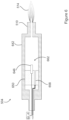
- FIG 6 is a schematic lengthwise cross-sectional view of the plasma generating device 504.
- the plasma generating device 504 includes an axially elongated plasma-generating chamber 642 enclosed by the main body 518 ( Figure 5 ). At least one "hot" or powered electrode 646 is positioned in the plasma-generating chamber 642.
- the plasma-generating chamber 642 may define a confined plasma-forming region 662 therein, proximate to the powered electrode 646.
- the plasma-generating chamber 642 may serve as a ground electrode or counter-electrode to the powered electrode 646 for generating plasma in the plasma-forming region 662.
- additional electrodes to which electrical potentials may be applied or which may be held at ground or electrically floating states, may be included as needed for generating an electrical field having a desired size, field strength, spatial orientation in the plasma-forming region 662.
- the plasma-generating chamber 642 may also serve as a conduit for flowing gases and plasma. Electrical connections to the powered electrode 646 may be made through an electrically insulating (e.g., dielectric) structure 650 located at the proximal end of or in the plasma-generating chamber 642.
- One or more gas passages 658 may be formed through the dielectric structure 650 in fluid communication with the plasma-generating chamber 642.
- the gas passages 658 may be placed in fluid communication with the gas inlet 522 ( Figure 5 ).
- the gas inlets 658 provide a flow path for plasma-generating gas (particularly air) fed to the plasma-forming region 662 proximate to the powered electrode 646.
- the plasma is generated in the plasma-forming region 662 and subsequently flows with the gas flow toward the plasma outlet 510 positioned at a distal end of the plasma-generating chamber 642.
- the gas passages 658 may be oriented at some angle to the central, longitudinal axis of the plasma-generating chamber 642, whereby gas is introduced into the plasma-generating chamber 642 with a significant tangential vector and consequently flows in the axial direction in a vortex flow pattern or path.
- the plasma outlet 510 may be widened in the transverse direction orthogonal to the longitudinal axis of the plasma-generating chamber 642 (i.e., along the axis orthogonally passing through the drawing sheet).
- the wide plasma outlet 510 may be realized by one or more wide exit slots, a linear of array of round exit openings, or a combination of both of the foregoing. Multiple exit slots or round openings may communicate with a single plasma-generating chamber 642 and associated electrode(s) (e.g., powered electrode 646) or by multiple plasma-generating units respective defined multiple groups of plasma-generating chambers and associated electrode(s).
- the plasma generating device 504 may produce a wide, predominantly linear or horizontally-oriented plasma plume or "plasma line" that extends the width of the plasma plume.
- FIG. 7 is a schematic lengthwise view of an example of a plasma system 700 according to another embodiment not forming part of the claimed invention.
- the plasma system 700 generally includes a plasma generating device 704, a plasma-generating gas supply source (not shown), and a power source 712.
- the plasma generating device 704 includes two planar (plate-shaped) electrodes, namely a first electrode 746 and a second electrode 748.
- the second electrode 748 is parallel to the first electrode 746, and is spaced from the first electrode 746 by an open gap 772.
- the size of the gap 772 i.e., the distance between the first electrode 746 and the second electrode 748) may be on the order of centimeters (cm).
- the plasma generating device 704 is configured to produce a dielectric barrier discharge (DBD) plasma.
- the plasma-generating gas supply source may be a chamber in which the electrodes 746 and 748 are located, or may include one or more components configured for establishing a flow of air (and optionally auxiliary gases) into the gap 772 where the plasma is generated.
- a portion of the structure defining such a chamber may serve as one of the electrodes 746 and 748.
- a metallic substrate 702 on which a metal oxide layer is to be formed is positioned in the gap 772 between the electrodes 746 and 748, and a non-thermal AP plasma having the attributes disclosed herein is generated between the electrodes 746 and 748.
- the methods disclosed herein may be implemented to form a nitride layer instead of an oxide layer, which serves as an adhesion promoting layer suitable for the use of certain types of adhesives.
- a non-thermal plasma is generated in air at atmospheric pressure that includes a significant amount of monatomic nitrogen ions (or other monatomic nitrogen species).
- the substrate surface of the metallic substrate is exposed to the non-thermal plasma, whereby the non-thermal plasma nitridizes the metallic substrate to form metal nitride from metal atoms of the metallic substrate.
- the metal nitride is formed as a metal nitride layer disposed directly on an underlying bulk metallic layer of the metallic substrate.
Landscapes
- Chemical & Material Sciences (AREA)
- Engineering & Computer Science (AREA)
- Organic Chemistry (AREA)
- Chemical Kinetics & Catalysis (AREA)
- Materials Engineering (AREA)
- Mechanical Engineering (AREA)
- Metallurgy (AREA)
- Plasma & Fusion (AREA)
- Physics & Mathematics (AREA)
- Spectroscopy & Molecular Physics (AREA)
- Plasma Technology (AREA)
- Manufacturing Of Printed Wiring (AREA)
- Chemical Vapour Deposition (AREA)
Claims (10)
- Procédé pour former une couche favorisant l'adhérence sur un substrat métallique (204, 404) comprenant dans son ensemble, à l'exception de traces d'impuretés, seulement un unique métal ou un unique alliage métallique, le procédé comprenant :le fait de générer un plasma non thermique dans de l'air à la pression atmosphérique dans une région plasmagène confinée (662) et le fait de faire s'écouler de l'air jusqu'à la région plasmagène (662), le plasma non thermique comprenant de l'oxygène monoatomique ;caractérisé parle fait que le substrat métallique (204, 404) comprend du titane,le fait d'exposer une surface de substrat (208) du substrat métallique (204, 404) à l'oxygène monoatomique dans le plasma émis à partir d'une sortie (510) dans lequel :l'oxygène monoatomique du plasma non thermique pénètre jusque dans le substrat métallique (204, 404) et oxyde le substrat métallique (204, 404) afin de former un oxyde métallique à partir des atomes de métal du substrat métallique ; etl'oxyde métallique est formé sous la forme d'une couche d'oxyde métallique (212, 412) comprenant de l'oxyde de titane disposé directement sur et fixé à une couche métallique massive sous-jacente (216, 416) du substrat métallique (204, 404),la couche d'oxyde métallique (212, 412) étant formée d'une seule pièce avec la couche métallique massive sous-jacente (216, 416) du substrat métallique (216, 416), de telle sorte que la couche d'oxyde métallique favorise le collage adhésif.
- Procédé selon la revendication 1, dans lequel le fait de générer le plasma non thermique comprend au moins l'un des éléments suivants :le fait de générer un champ électrique en présence d'air ;le fait de générer un champ électrique en présence d'air, dans lequel le fait de générer le champ électrique comprend le fait d'appliquer une tension entre deux électrodes dans une gamme allant de 1 kV à 50 kV, dans lequel le champ électrique a de préférence une intensité de champ comprise dans une gamme allant de 1 kV/cm à 500 kV/cm ;le fait de générer le plasma non thermique dans une région plasmagène confinée (662), et le fait de faire s'écouler de l'air jusqu'à la région plasmagène, dans lequel l'air est de préférence amené à s'écouler à un débit d'air compris dans une gamme allant de 1 SLM à 5 000 SLM ;le plasma non thermique a une densité de puissance appliquée comprise dans une gamme allant de 0,25 kW/cm3 à 400 kW/cm3.
- Procédé selon la revendication 1 ou 2, comprenant au moins l'un des
éléments suivants :
avant ou durant l'exposition de la surface de substrat (208) au plasma non thermique, le fait de chauffer le substrat métallique (204, 404), de préférence par chauffage du substrat métallique (204, 404) jusqu'à une température comprise dans une gamme allant de 0 °C à 400 °C. - Procédé selon l'une quelconque des revendications précédentes, comprenant au moins l'un des éléments suivants :
avant ou durant la génération du plasma non thermique, le fait de faire s'écouler du gaz oxygène diatomique jusque dans la région plasmagène confinée afin d'augmenter une concentration d'oxygène diatomique dans la région plasmagène confinée ; avant ou durant la génération du plasma non thermique, le fait de faire s'écouler un gaz auxiliaire jusque dans la région plasmagène confinée, dans lequel le gaz auxiliaire est de préférence sélectionné dans le groupe constitué : de l'azote diatomique, du fluor diatomique, du chlore diatomique, du brome diatomique, de l'iode diatomique, d'un composé d'azote, d'un composé de fluor, d'un composé de chlore, d'un composé de brome, d'un composé d'iode, d'un composé de bore, d'un composé de carbone, d'un composé d'oxygène, d'un composé de soufre, d'un composé de phosphore, d'un composé de silicium, d'un composé de sélénium, d'un composé de tellure, et d'une combinaison de deux ou plus de ces derniers. - Procédé selon l'une quelconque des revendications précédentes, dans lequel :le fait de générer le plasma non thermique comprend le fait de générer le plasma non thermique dans une chambre (662) ; etle fait d'exposer la surface de substrat (208) au plasma non thermique comprend le fait de faire s'écouler le plasma non thermique depuis la chambre, à travers une sortie (510), et vers la surface de substrat (208).
- Procédé selon l'une quelconque des revendications précédentes, comprenant au moins l'un des cas suivants :dans lequel la couche d'oxyde métallique (212, 412) présente une surface d'oxyde externe (220, 420) et présente une épaisseur définie à partir de la couche métallique massive sous-jacente (216, 416) jusqu'à la surface d'oxyde externe, et l'épaisseur est inférieure à 1 000 nanomètres, en particulier comprise dans une gamme allant de 1 nm à 100 nm ;dans lequel la couche d'oxyde métallique (212, 412) présente une surface externe (220, 420) ayant une énergie de surface supérieure à une énergie de surface de la surface de substrat (208) préalablement au fait que la surface de substrat soit exposée au plasma non thermique.
- Procédé pour coller un substrat métallique (204, 404) sur un objet (430), le procédé comprenant :le fait de fournir un substrat métallique (204, 404) comprenant une couche d'oxyde métallique (212, 412) formée sur celui-ci selon le procédé selon l'une quelconque des revendications précédentes 1 à 6 ; etle fait de fournir une couche adhésive (424) sur la couche d'oxyde métallique (212, 412),dans lequel en particulier le fait de fournir la couche adhésive est sélectionné dans le groupe constitué : du fait de distribuer un matériau adhésif dans un état coulant sur la couche d'oxyde métallique (212, 412) ; et du fait de placer un matériau adhésif sous une forme solide ou de gel sur la couche d'oxyde métallique.
- Procédé selon la revendication 7, comprenant le fait de monter l'objet (430) sur la couche adhésive (424).
- Substrat métallique oxydé (204, 404), le substrat métallique comprenant :une couche métallique massive (216, 416) ; etune couche d'oxyde métallique (212, 412) disposée directement sur la couche métallique massive sous-jacente (216, 416), dans lequel la couche d'oxyde métallique (212, 412) est formée d'une seule pièce avec la couche métallique massive sous-jacente (216, 416) du substrat métallique (204, 404), et sert de couche favorisant l'adhérence disposée sur la couche métallique massive (216, 416) efficace pour favoriser l'adhérence du substrat métallique (204, 404) sur un objet (430),dans lequella couche métallique massive (216, 416) comprend du titane,la couche d'oxyde métallique (212, 412) est formée par de l'oxygène monoatomique mis à réagir avec des atomes de titane du titane dans le substrat métallique (204, 404), etla couche d'oxyde métallique (212, 412) comprend de l'oxyde de titane.
- Article, comprenant :un substrat métallique comprenant une couche d'oxyde métallique (212, 412) formée sur celui-ci selon la revendication 9,une couche adhésive (424) sur la couche d'oxyde métallique (212, 412), etun objet (430) monté sur la couche adhésive (424).
Applications Claiming Priority (2)
| Application Number | Priority Date | Filing Date | Title |
|---|---|---|---|
| US201562258522P | 2015-11-22 | 2015-11-22 | |
| PCT/US2016/063392 WO2017087991A1 (fr) | 2015-11-22 | 2016-11-22 | Procédé et dispositif favorisant l'adhérence de surfaces métalliques |
Publications (4)
| Publication Number | Publication Date |
|---|---|
| EP3377668A1 EP3377668A1 (fr) | 2018-09-26 |
| EP3377668A4 EP3377668A4 (fr) | 2019-07-17 |
| EP3377668C0 EP3377668C0 (fr) | 2025-05-21 |
| EP3377668B1 true EP3377668B1 (fr) | 2025-05-21 |
Family
ID=58717975
Family Applications (1)
| Application Number | Title | Priority Date | Filing Date |
|---|---|---|---|
| EP16867366.3A Active EP3377668B1 (fr) | 2015-11-22 | 2016-11-22 | Procédé et dispositif favorisant l'adhérence de surfaces métalliques |
Country Status (5)
| Country | Link |
|---|---|
| US (3) | US11041235B2 (fr) |
| EP (1) | EP3377668B1 (fr) |
| CA (1) | CA3006855A1 (fr) |
| MX (2) | MX2018006317A (fr) |
| WO (1) | WO2017087991A1 (fr) |
Families Citing this family (7)
| Publication number | Priority date | Publication date | Assignee | Title |
|---|---|---|---|---|
| US20190078191A1 (en) * | 2017-09-14 | 2019-03-14 | Atmospheric Plasma Solutions, Inc. | Method and system for promoting adhesion of arc-spray coatings |
| US11629860B2 (en) | 2018-07-17 | 2023-04-18 | Transient Plasma Systems, Inc. | Method and system for treating emissions using a transient pulsed plasma |
| CA3117338C (fr) * | 2018-10-24 | 2023-04-04 | Atmospheric Plasma Solutions, Inc. | Source de plasma et procede de preparation et de revetement de surfaces a l'aide d'ondes de pression de plasma atmospherique |
| WO2020226977A1 (fr) * | 2019-05-07 | 2020-11-12 | Transient Plasma Systems, Inc. | Système de traitement par plasma à pression atmosphérique non thermique pulsée |
| WO2020248245A1 (fr) * | 2019-06-14 | 2020-12-17 | 清华-伯克利深圳学院筹备办公室 | Matériau monoatomique, son procédé de préparation et son utilisation |
| US20220042176A1 (en) * | 2020-08-07 | 2022-02-10 | Ut-Battelle, Llc | Advanced anticorrosion coatings on lightweight magnesium alloys by atmospheric co2 plasma treatment |
| US12110584B2 (en) * | 2021-06-28 | 2024-10-08 | Applied Materials, Inc. | Low temperature growth of transition metal chalcogenides |
Family Cites Families (41)
| Publication number | Priority date | Publication date | Assignee | Title |
|---|---|---|---|---|
| DE1571153A1 (de) | 1962-08-25 | 1970-08-13 | Siemens Ag | Plasmaspritzpistole |
| US4788402A (en) | 1987-03-11 | 1988-11-29 | Browning James A | High power extended arc plasma spray method and apparatus |
| US5313931A (en) | 1991-11-20 | 1994-05-24 | Newell Operating Company | One hand fixed temperature coating remover |
| US5414324A (en) | 1993-05-28 | 1995-05-09 | The University Of Tennessee Research Corporation | One atmosphere, uniform glow discharge plasma |
| US5976992A (en) | 1993-09-27 | 1999-11-02 | Kabushiki Kaisha Toshiba | Method of supplying excited oxygen |
| JP2003027210A (ja) * | 1994-07-04 | 2003-01-29 | Seiko Epson Corp | 表面処理方法及び表示装置の製造方法 |
| US6291343B1 (en) * | 1994-11-14 | 2001-09-18 | Applied Materials, Inc. | Plasma annealing of substrates to improve adhesion |
| US5749937A (en) | 1995-03-14 | 1998-05-12 | Lockheed Idaho Technologies Company | Fast quench reactor and method |
| US5928527A (en) | 1996-04-15 | 1999-07-27 | The Boeing Company | Surface modification using an atmospheric pressure glow discharge plasma source |
| US5913144A (en) | 1996-09-20 | 1999-06-15 | Sharp Microelectronics Technology, Inc. | Oxidized diffusion barrier surface for the adherence of copper and method for same |
| US5970993A (en) | 1996-10-04 | 1999-10-26 | Utron Inc. | Pulsed plasma jet paint removal |
| US5961772A (en) | 1997-01-23 | 1999-10-05 | The Regents Of The University Of California | Atmospheric-pressure plasma jet |
| US5922412A (en) | 1998-03-26 | 1999-07-13 | Ford Global Technologies, Inc. | Method of eliminating unevenness in pass-reversal thermal spraying |
| US6262523B1 (en) | 1999-04-21 | 2001-07-17 | The Regents Of The University Of California | Large area atmospheric-pressure plasma jet |
| US7025856B2 (en) | 2001-02-02 | 2006-04-11 | The Regents Of The University Of California | Processing materials inside an atmospheric-pressure radiofrequency nonthermal plasma discharge |
| US7288293B2 (en) * | 2001-03-27 | 2007-10-30 | Apit Corp. S.A. | Process for plasma surface treatment and device for realizing the process |
| WO2002093996A1 (fr) | 2001-05-10 | 2002-11-21 | Parker Hannifin Corporation | Fabrication d'une enveloppe electronique dotee d'une couche de protection metallisee |
| DE60221290T2 (de) | 2002-01-29 | 2008-04-03 | Sit La Precisa S.P.A. | Eine ventileinheit für modulation von auslassdruck eines gasses |
| US6967304B2 (en) | 2002-04-29 | 2005-11-22 | Cyber Materials Llc | Feedback enhanced plasma spray tool |
| DE10257344A1 (de) * | 2002-12-06 | 2004-07-08 | OTB Oberflächentechnik in Berlin GmbH & Co. | Verfahren zur Konservierung von Metalloberflächen |
| US7507678B2 (en) * | 2004-03-26 | 2009-03-24 | Sekesui Chemical Co., Ltd. | Method and apparatus for forming oxynitride film and nitride film, oxynitride film, nitride film, and substrate |
| WO2006007437A1 (fr) | 2004-06-16 | 2006-01-19 | Ppg Industries Ohio, Inc. | Procedes d'elimination de couches de revetement polymeriques de substrats revetus |
| US20060052883A1 (en) | 2004-09-08 | 2006-03-09 | Lee Sang H | System and method for optimizing data acquisition of plasma using a feedback control module |
| WO2006048650A1 (fr) | 2004-11-05 | 2006-05-11 | Dow Corning Ireland Limited | Systeme a plasma |
| US20060156983A1 (en) | 2005-01-19 | 2006-07-20 | Surfx Technologies Llc | Low temperature, atmospheric pressure plasma generation and applications |
| WO2007008755A2 (fr) | 2005-07-08 | 2007-01-18 | The Board Of Regents, The University Of Texas System | Fonctionnalisation de surface de materiaux polymeres |
| US7608839B2 (en) | 2005-08-05 | 2009-10-27 | Mcgill University | Plasma source and applications thereof |
| JP5060038B2 (ja) * | 2005-10-07 | 2012-10-31 | ルネサスエレクトロニクス株式会社 | 電子回路装置およびその製造方法 |
| US20070231590A1 (en) * | 2006-03-31 | 2007-10-04 | Stellar Industries Corp. | Method of Bonding Metals to Ceramics |
| GB0717430D0 (en) * | 2007-09-10 | 2007-10-24 | Dow Corning Ireland Ltd | Atmospheric pressure plasma |
| CN101227790B (zh) | 2008-01-25 | 2011-01-26 | 华中科技大学 | 等离子体喷流装置 |
| US8658258B2 (en) | 2008-10-21 | 2014-02-25 | Aculon, Inc. | Plasma treatment of substrates prior to the formation a self-assembled monolayer |
| EP2396457A2 (fr) | 2009-02-08 | 2011-12-21 | AP Solutions, Inc. | Source de plasma avec lame intégrée et procédé d'élimination de matériaux de substrats |
| US7964822B2 (en) | 2009-02-23 | 2011-06-21 | Chi Ming Suen | Paint remover for use with a heat gun |
| US8361334B2 (en) | 2009-03-18 | 2013-01-29 | Medtronic, Inc. | Plasma deposition to increase adhesion |
| JP5694543B2 (ja) * | 2011-09-08 | 2015-04-01 | 東芝三菱電機産業システム株式会社 | プラズマ発生装置、cvd装置およびプラズマ処理粒子生成装置 |
| GB201116025D0 (en) * | 2011-09-16 | 2011-10-26 | Surface Innovations Ltd | Method |
| DE102012102721B4 (de) * | 2012-03-29 | 2013-12-05 | BSH Bosch und Siemens Hausgeräte GmbH | Verfahren zum Passivieren einer Metalloberfläche |
| JP6153118B2 (ja) * | 2013-08-30 | 2017-06-28 | 国立研究開発法人産業技術総合研究所 | マイクロ波プラズマ処理装置 |
| US9406485B1 (en) * | 2013-12-18 | 2016-08-02 | Surfx Technologies Llc | Argon and helium plasma apparatus and methods |
| US9737964B2 (en) | 2015-05-18 | 2017-08-22 | Caterpillar Inc. | Steam oxidation of thermal spray substrate |
-
2016
- 2016-11-22 US US15/776,692 patent/US11041235B2/en active Active
- 2016-11-22 WO PCT/US2016/063392 patent/WO2017087991A1/fr not_active Ceased
- 2016-11-22 CA CA3006855A patent/CA3006855A1/fr active Pending
- 2016-11-22 MX MX2018006317A patent/MX2018006317A/es unknown
- 2016-11-22 EP EP16867366.3A patent/EP3377668B1/fr active Active
-
2018
- 2018-05-22 MX MX2023004919A patent/MX2023004919A/es unknown
-
2021
- 2021-01-29 US US17/162,774 patent/US11384420B2/en active Active
-
2022
- 2022-07-11 US US17/861,525 patent/US20220341022A1/en active Pending
Non-Patent Citations (1)
| Title |
|---|
| KUROMOTO ET AL: "Titanium oxide films produced on commercially pure titanium by anodic oxidation with different voltages", MATERIALS CHARACTERIZATION, ELSEVIER, NEW YORK, NY, US, vol. 58, no. 2, 26 January 2007 (2007-01-26), pages 114 - 121, XP005862529, ISSN: 1044-5803, DOI: 10.1016/J.MATCHAR.2006.03.020 * |
Also Published As
| Publication number | Publication date |
|---|---|
| MX2023004919A (es) | 2023-05-16 |
| US20210147972A1 (en) | 2021-05-20 |
| WO2017087991A1 (fr) | 2017-05-26 |
| US20180363124A1 (en) | 2018-12-20 |
| US20220341022A1 (en) | 2022-10-27 |
| US11384420B2 (en) | 2022-07-12 |
| US11041235B2 (en) | 2021-06-22 |
| MX2018006317A (es) | 2019-01-31 |
| CA3006855A1 (fr) | 2017-05-26 |
| EP3377668A1 (fr) | 2018-09-26 |
| EP3377668C0 (fr) | 2025-05-21 |
| EP3377668A4 (fr) | 2019-07-17 |
Similar Documents
| Publication | Publication Date | Title |
|---|---|---|
| US11384420B2 (en) | Method and device for promoting adhesion of metallic surfaces | |
| JP6329742B2 (ja) | リモートアーク放電プラズマアシスト処理 | |
| KR20100108322A (ko) | 대기압 플라즈마 | |
| JP6625728B2 (ja) | プラズマ生成装置 | |
| Chen et al. | Surface modification of tube inner wall by transferred atmospheric pressure plasma | |
| MXPA01002047A (es) | Procedimiento para el activado superficial de materiales en forma de banda. | |
| JP2013538288A (ja) | 基板のプラズマ処理 | |
| US20110129617A1 (en) | Plasma system and method of producing a functional coating | |
| JP2001516947A (ja) | マイクロ波の入射によりプラズマを発生させる方法 | |
| EP3619734B1 (fr) | Source plasma linéaire à cathode creuse segmentée | |
| Krumpolec et al. | Multi-hollow surface dielectric barrier discharge for plasma treatment of patterned silicon surfaces | |
| Abou Rich et al. | LDPE surface modifications induced by atmospheric plasma torches with linear and showerhead configurations | |
| Pal et al. | Enhancement of adhesion of polymers by plasma treatment: a critical review | |
| Fang et al. | Plasma-enabled healing of graphene nano-platelets layer | |
| Mello et al. | Surface modification of polycarbonate by atmospheric-pressure plasma jets | |
| Kusano | Plasma surface modification at atmospheric pressure | |
| US20190078191A1 (en) | Method and system for promoting adhesion of arc-spray coatings | |
| JP5956302B2 (ja) | プラズマ処理装置、ヘテロ膜の形成方法 | |
| Ohtsu et al. | Atmospheric-pressure plasma jet system for silicon etching without fluorocarbon gas feed | |
| Jang et al. | Discharge study of argon DC arc jet assisted by DBD plasma for metal surface treatment | |
| Fei et al. | High-density polyethylene (HDPE) surface treatment using an RF capacitive atmospheric pressure cold Ar plasma jet | |
| RU2848813C1 (ru) | Способ модификации поверхности сталей 20х13 и 38х2мюа азотированием в радиочастотной индуктивно-связанной плазме и нанесением покрытия из нитрида хрома магнетронным распылением | |
| Korzec et al. | Pre‐and Post‐processes | |
| Watanabe et al. | Formation of aC thin films by plasma-based ion implantation | |
| Thomas et al. | Coating with atmospheric pressure plasma processes: From large area to µ-structures |
Legal Events
| Date | Code | Title | Description |
|---|---|---|---|
| STAA | Information on the status of an ep patent application or granted ep patent |
Free format text: STATUS: THE INTERNATIONAL PUBLICATION HAS BEEN MADE |
|
| PUAI | Public reference made under article 153(3) epc to a published international application that has entered the european phase |
Free format text: ORIGINAL CODE: 0009012 |
|
| STAA | Information on the status of an ep patent application or granted ep patent |
Free format text: STATUS: REQUEST FOR EXAMINATION WAS MADE |
|
| 17P | Request for examination filed |
Effective date: 20180614 |
|
| AK | Designated contracting states |
Kind code of ref document: A1 Designated state(s): AL AT BE BG CH CY CZ DE DK EE ES FI FR GB GR HR HU IE IS IT LI LT LU LV MC MK MT NL NO PL PT RO RS SE SI SK SM TR |
|
| AX | Request for extension of the european patent |
Extension state: BA ME |
|
| DAV | Request for validation of the european patent (deleted) | ||
| DAX | Request for extension of the european patent (deleted) | ||
| A4 | Supplementary search report drawn up and despatched |
Effective date: 20190619 |
|
| RIC1 | Information provided on ipc code assigned before grant |
Ipc: C23C 8/36 20060101AFI20190613BHEP Ipc: H05H 1/24 20060101ALI20190613BHEP Ipc: C23C 8/10 20060101ALI20190613BHEP |
|
| STAA | Information on the status of an ep patent application or granted ep patent |
Free format text: STATUS: EXAMINATION IS IN PROGRESS |
|
| 17Q | First examination report despatched |
Effective date: 20200728 |
|
| GRAP | Despatch of communication of intention to grant a patent |
Free format text: ORIGINAL CODE: EPIDOSNIGR1 |
|
| STAA | Information on the status of an ep patent application or granted ep patent |
Free format text: STATUS: GRANT OF PATENT IS INTENDED |
|
| INTG | Intention to grant announced |
Effective date: 20241212 |
|
| GRAS | Grant fee paid |
Free format text: ORIGINAL CODE: EPIDOSNIGR3 |
|
| GRAA | (expected) grant |
Free format text: ORIGINAL CODE: 0009210 |
|
| STAA | Information on the status of an ep patent application or granted ep patent |
Free format text: STATUS: THE PATENT HAS BEEN GRANTED |
|
| AK | Designated contracting states |
Kind code of ref document: B1 Designated state(s): AL AT BE BG CH CY CZ DE DK EE ES FI FR GB GR HR HU IE IS IT LI LT LU LV MC MK MT NL NO PL PT RO RS SE SI SK SM TR |
|
| REG | Reference to a national code |
Ref country code: GB Ref legal event code: FG4D |
|
| REG | Reference to a national code |
Ref country code: CH Ref legal event code: EP |
|
| REG | Reference to a national code |
Ref country code: IE Ref legal event code: FG4D |
|
| U01 | Request for unitary effect filed |
Effective date: 20250521 |
|
| U07 | Unitary effect registered |
Designated state(s): AT BE BG DE DK EE FI FR IT LT LU LV MT NL PT RO SE SI Effective date: 20250527 |
|
| PG25 | Lapsed in a contracting state [announced via postgrant information from national office to epo] |
Ref country code: ES Free format text: LAPSE BECAUSE OF FAILURE TO SUBMIT A TRANSLATION OF THE DESCRIPTION OR TO PAY THE FEE WITHIN THE PRESCRIBED TIME-LIMIT Effective date: 20250521 |
|
| PG25 | Lapsed in a contracting state [announced via postgrant information from national office to epo] |
Ref country code: GR Free format text: LAPSE BECAUSE OF FAILURE TO SUBMIT A TRANSLATION OF THE DESCRIPTION OR TO PAY THE FEE WITHIN THE PRESCRIBED TIME-LIMIT Effective date: 20250822 Ref country code: NO Free format text: LAPSE BECAUSE OF FAILURE TO SUBMIT A TRANSLATION OF THE DESCRIPTION OR TO PAY THE FEE WITHIN THE PRESCRIBED TIME-LIMIT Effective date: 20250821 |
|
| PG25 | Lapsed in a contracting state [announced via postgrant information from national office to epo] |
Ref country code: PL Free format text: LAPSE BECAUSE OF FAILURE TO SUBMIT A TRANSLATION OF THE DESCRIPTION OR TO PAY THE FEE WITHIN THE PRESCRIBED TIME-LIMIT Effective date: 20250521 |
|
| PG25 | Lapsed in a contracting state [announced via postgrant information from national office to epo] |
Ref country code: HR Free format text: LAPSE BECAUSE OF FAILURE TO SUBMIT A TRANSLATION OF THE DESCRIPTION OR TO PAY THE FEE WITHIN THE PRESCRIBED TIME-LIMIT Effective date: 20250521 |
|
| PG25 | Lapsed in a contracting state [announced via postgrant information from national office to epo] |
Ref country code: RS Free format text: LAPSE BECAUSE OF FAILURE TO SUBMIT A TRANSLATION OF THE DESCRIPTION OR TO PAY THE FEE WITHIN THE PRESCRIBED TIME-LIMIT Effective date: 20250821 |
|
| PG25 | Lapsed in a contracting state [announced via postgrant information from national office to epo] |
Ref country code: IS Free format text: LAPSE BECAUSE OF FAILURE TO SUBMIT A TRANSLATION OF THE DESCRIPTION OR TO PAY THE FEE WITHIN THE PRESCRIBED TIME-LIMIT Effective date: 20250921 |
|
| U20 | Renewal fee for the european patent with unitary effect paid |
Year of fee payment: 10 Effective date: 20251124 |
|
| PGFP | Annual fee paid to national office [announced via postgrant information from national office to epo] |
Ref country code: GB Payment date: 20251119 Year of fee payment: 10 |
|
| PG25 | Lapsed in a contracting state [announced via postgrant information from national office to epo] |
Ref country code: SM Free format text: LAPSE BECAUSE OF FAILURE TO SUBMIT A TRANSLATION OF THE DESCRIPTION OR TO PAY THE FEE WITHIN THE PRESCRIBED TIME-LIMIT Effective date: 20250521 |
|
| PG25 | Lapsed in a contracting state [announced via postgrant information from national office to epo] |
Ref country code: CZ Free format text: LAPSE BECAUSE OF FAILURE TO SUBMIT A TRANSLATION OF THE DESCRIPTION OR TO PAY THE FEE WITHIN THE PRESCRIBED TIME-LIMIT Effective date: 20250521 |
|
| PG25 | Lapsed in a contracting state [announced via postgrant information from national office to epo] |
Ref country code: SK Free format text: LAPSE BECAUSE OF FAILURE TO SUBMIT A TRANSLATION OF THE DESCRIPTION OR TO PAY THE FEE WITHIN THE PRESCRIBED TIME-LIMIT Effective date: 20250521 |
|
| PLBE | No opposition filed within time limit |
Free format text: ORIGINAL CODE: 0009261 |
|
| STAA | Information on the status of an ep patent application or granted ep patent |
Free format text: STATUS: NO OPPOSITION FILED WITHIN TIME LIMIT |
|
| REG | Reference to a national code |
Ref country code: CH Ref legal event code: L10 Free format text: ST27 STATUS EVENT CODE: U-0-0-L10-L00 (AS PROVIDED BY THE NATIONAL OFFICE) Effective date: 20260402 |
|
| 26N | No opposition filed |
Effective date: 20260224 |