EP3377720B1 - Verbindungsstück für winkelverbindung von hohlprofilelementen und verfahren unter verwendung eines derartigen verbindungsstückes - Google Patents
Verbindungsstück für winkelverbindung von hohlprofilelementen und verfahren unter verwendung eines derartigen verbindungsstückes Download PDFInfo
- Publication number
- EP3377720B1 EP3377720B1 EP16825876.2A EP16825876A EP3377720B1 EP 3377720 B1 EP3377720 B1 EP 3377720B1 EP 16825876 A EP16825876 A EP 16825876A EP 3377720 B1 EP3377720 B1 EP 3377720B1
- Authority
- EP
- European Patent Office
- Prior art keywords
- hollow profile
- profile members
- sheet metal
- base portion
- chambers
- Prior art date
- Legal status (The legal status is an assumption and is not a legal conclusion. Google has not performed a legal analysis and makes no representation as to the accuracy of the status listed.)
- Active
Links
Images




Classifications
-
- E—FIXED CONSTRUCTIONS
- E06—DOORS, WINDOWS, SHUTTERS, OR ROLLER BLINDS IN GENERAL; LADDERS
- E06B—FIXED OR MOVABLE CLOSURES FOR OPENINGS IN BUILDINGS, VEHICLES, FENCES OR LIKE ENCLOSURES IN GENERAL, e.g. DOORS, WINDOWS, BLINDS, GATES
- E06B3/00—Window sashes, door leaves, or like elements for closing wall or like openings; Layout of fixed or moving closures, e.g. windows in wall or like openings; Features of rigidly-mounted outer frames relating to the mounting of wing frames
- E06B3/96—Corner joints or edge joints for windows, doors, or the like frames or wings
- E06B3/964—Corner joints or edge joints for windows, doors, or the like frames or wings using separate connection pieces, e.g. T-connection pieces
- E06B3/9644—L-shaped corner pieces having two articulated or flexible joined legs; Corner joints with variable angle
-
- E—FIXED CONSTRUCTIONS
- E06—DOORS, WINDOWS, SHUTTERS, OR ROLLER BLINDS IN GENERAL; LADDERS
- E06B—FIXED OR MOVABLE CLOSURES FOR OPENINGS IN BUILDINGS, VEHICLES, FENCES OR LIKE ENCLOSURES IN GENERAL, e.g. DOORS, WINDOWS, BLINDS, GATES
- E06B3/00—Window sashes, door leaves, or like elements for closing wall or like openings; Layout of fixed or moving closures, e.g. windows in wall or like openings; Features of rigidly-mounted outer frames relating to the mounting of wing frames
- E06B3/96—Corner joints or edge joints for windows, doors, or the like frames or wings
- E06B3/964—Corner joints or edge joints for windows, doors, or the like frames or wings using separate connection pieces, e.g. T-connection pieces
- E06B3/968—Corner joints or edge joints for windows, doors, or the like frames or wings using separate connection pieces, e.g. T-connection pieces characterised by the way the connecting pieces are fixed in or on the frame members
- E06B3/972—Corner joints or edge joints for windows, doors, or the like frames or wings using separate connection pieces, e.g. T-connection pieces characterised by the way the connecting pieces are fixed in or on the frame members by increasing the cross-section of the connecting pieces, e.g. by expanding the connecting pieces with wedges
-
- E—FIXED CONSTRUCTIONS
- E06—DOORS, WINDOWS, SHUTTERS, OR ROLLER BLINDS IN GENERAL; LADDERS
- E06B—FIXED OR MOVABLE CLOSURES FOR OPENINGS IN BUILDINGS, VEHICLES, FENCES OR LIKE ENCLOSURES IN GENERAL, e.g. DOORS, WINDOWS, BLINDS, GATES
- E06B3/00—Window sashes, door leaves, or like elements for closing wall or like openings; Layout of fixed or moving closures, e.g. windows in wall or like openings; Features of rigidly-mounted outer frames relating to the mounting of wing frames
- E06B3/04—Wing frames not characterised by the manner of movement
- E06B3/06—Single frames
-
- E—FIXED CONSTRUCTIONS
- E06—DOORS, WINDOWS, SHUTTERS, OR ROLLER BLINDS IN GENERAL; LADDERS
- E06B—FIXED OR MOVABLE CLOSURES FOR OPENINGS IN BUILDINGS, VEHICLES, FENCES OR LIKE ENCLOSURES IN GENERAL, e.g. DOORS, WINDOWS, BLINDS, GATES
- E06B3/00—Window sashes, door leaves, or like elements for closing wall or like openings; Layout of fixed or moving closures, e.g. windows in wall or like openings; Features of rigidly-mounted outer frames relating to the mounting of wing frames
- E06B3/96—Corner joints or edge joints for windows, doors, or the like frames or wings
- E06B3/964—Corner joints or edge joints for windows, doors, or the like frames or wings using separate connection pieces, e.g. T-connection pieces
- E06B3/968—Corner joints or edge joints for windows, doors, or the like frames or wings using separate connection pieces, e.g. T-connection pieces characterised by the way the connecting pieces are fixed in or on the frame members
- E06B3/9687—Corner joints or edge joints for windows, doors, or the like frames or wings using separate connection pieces, e.g. T-connection pieces characterised by the way the connecting pieces are fixed in or on the frame members with screws blocking the connecting piece inside or on the frame member
- E06B3/9688—Mitre joints
-
- E—FIXED CONSTRUCTIONS
- E06—DOORS, WINDOWS, SHUTTERS, OR ROLLER BLINDS IN GENERAL; LADDERS
- E06B—FIXED OR MOVABLE CLOSURES FOR OPENINGS IN BUILDINGS, VEHICLES, FENCES OR LIKE ENCLOSURES IN GENERAL, e.g. DOORS, WINDOWS, BLINDS, GATES
- E06B3/00—Window sashes, door leaves, or like elements for closing wall or like openings; Layout of fixed or moving closures, e.g. windows in wall or like openings; Features of rigidly-mounted outer frames relating to the mounting of wing frames
- E06B3/96—Corner joints or edge joints for windows, doors, or the like frames or wings
- E06B3/964—Corner joints or edge joints for windows, doors, or the like frames or wings using separate connection pieces, e.g. T-connection pieces
- E06B3/968—Corner joints or edge joints for windows, doors, or the like frames or wings using separate connection pieces, e.g. T-connection pieces characterised by the way the connecting pieces are fixed in or on the frame members
- E06B3/98—Corner joints or edge joints for windows, doors, or the like frames or wings using separate connection pieces, e.g. T-connection pieces characterised by the way the connecting pieces are fixed in or on the frame members the connecting pieces being specially adapted for drawing the frame members towards each other
- E06B3/982—Mitre joints
-
- E—FIXED CONSTRUCTIONS
- E06—DOORS, WINDOWS, SHUTTERS, OR ROLLER BLINDS IN GENERAL; LADDERS
- E06B—FIXED OR MOVABLE CLOSURES FOR OPENINGS IN BUILDINGS, VEHICLES, FENCES OR LIKE ENCLOSURES IN GENERAL, e.g. DOORS, WINDOWS, BLINDS, GATES
- E06B3/00—Window sashes, door leaves, or like elements for closing wall or like openings; Layout of fixed or moving closures, e.g. windows in wall or like openings; Features of rigidly-mounted outer frames relating to the mounting of wing frames
- E06B3/96—Corner joints or edge joints for windows, doors, or the like frames or wings
- E06B3/964—Corner joints or edge joints for windows, doors, or the like frames or wings using separate connection pieces, e.g. T-connection pieces
- E06B3/968—Corner joints or edge joints for windows, doors, or the like frames or wings using separate connection pieces, e.g. T-connection pieces characterised by the way the connecting pieces are fixed in or on the frame members
- E06B3/9684—Corner joints or edge joints for windows, doors, or the like frames or wings using separate connection pieces, e.g. T-connection pieces characterised by the way the connecting pieces are fixed in or on the frame members by hooking protrusions on the connecting piece in openings of the frame member, e.g. by snap-locking
- E06B3/9685—Mitre joints
-
- E—FIXED CONSTRUCTIONS
- E06—DOORS, WINDOWS, SHUTTERS, OR ROLLER BLINDS IN GENERAL; LADDERS
- E06B—FIXED OR MOVABLE CLOSURES FOR OPENINGS IN BUILDINGS, VEHICLES, FENCES OR LIKE ENCLOSURES IN GENERAL, e.g. DOORS, WINDOWS, BLINDS, GATES
- E06B3/00—Window sashes, door leaves, or like elements for closing wall or like openings; Layout of fixed or moving closures, e.g. windows in wall or like openings; Features of rigidly-mounted outer frames relating to the mounting of wing frames
- E06B3/96—Corner joints or edge joints for windows, doors, or the like frames or wings
- E06B3/964—Corner joints or edge joints for windows, doors, or the like frames or wings using separate connection pieces, e.g. T-connection pieces
- E06B3/968—Corner joints or edge joints for windows, doors, or the like frames or wings using separate connection pieces, e.g. T-connection pieces characterised by the way the connecting pieces are fixed in or on the frame members
- E06B3/972—Corner joints or edge joints for windows, doors, or the like frames or wings using separate connection pieces, e.g. T-connection pieces characterised by the way the connecting pieces are fixed in or on the frame members by increasing the cross-section of the connecting pieces, e.g. by expanding the connecting pieces with wedges
- E06B3/9725—Mitre joints
Definitions
- the invention relates to a joint employed in the process of angular connection of hollow profile members used to form parallelepipedal frames for doors or windows such frames being filled with glazing or shutter panels.
- a variety of joints is used in the angular connection of hollow profile members with their edges being cut at an angle of 45° and brought in matching contact to form door or window frames, partitions or other applications.
- the hollow profile members are cut at an angle of 45° in each corner of the generally rectangular frame of either the frame profile member that is fixedly mounted onto the wall surrounding a door or window opening or of the sash profile member operationally mounted therein.
- a joint item is thereafter being introduced within abutting chambers of a pair of hollow profile members being brought in matching contact at each one of the corners of the aforementioned generally rectangular frame, the joint providing a stable connection of such profile members.
- Prior art joints generally comprised spring activated button means detachably engaging into suitable apertures provided at the corners of the hollow profile members being connected, such joints being adapted to stabilize the angular connection thereof.
- spring activated button means detachably engaging into suitable apertures provided at the corners of the hollow profile members being connected, such joints being adapted to stabilize the angular connection thereof.
- These prior art joints required, prior to employment thereof, the opening of apertures at accurately selected locations of the hollow profile members wherein are engaged the abovementioned spring activated buttons. This process is awkward and time consuming due to the accuracy required in marking and drilling of the apertures and often leads to an imperfect fit of the profiles and to a structure of reduced aesthetics and functionality due to the erroneous alignment of the hollow profile members brought in matching contact or to a loosening of tightening of the joint in the course of time.
- WO 2004/033837 of Athanasios Leontaridis discloses a joint for the angular connection of frames for doors and windows, according to the preamble of claim 1, such joint comprising a slide base portion with side parts inserted within the abutting chambers of a pair of hollow profile members being connected and an analogously configured sheet metal mobile portion superimposed thereupon, the sheet metal mobile portion including upwardly extending legs with indenting edges, a bolt passing through a single hole that is required in this disclosure, ach bolt being employed in the tightening process of the joint, wherein after the joint has been inserted into the hollow profile members being brought together for connection, the bolt acts so as to exert an upwardly raising force onto the sheet metal mobile portion, whilst maintaining the slide base portion at a fixed position, and subsequently leading the sharp indenting edges of the sheet metal portion to produce an indentation effect into the walls of the corresponding chambers of the hollow profiles being angularly connected with the joint, as the bolt is being tightened, thereby resulting in a
- the hereinabove angular joint disclosed in WO-2004/033837 with its symmetrical arrangement on either side of a plane of symmetry passing though the plane of matching contact of the hollow profile members being connected has contributed in overcoming the aforementioned problems of joints of the prior art, since it substantially facilitates the user, i.e. the technician who assembles doors or windows through angularly connecting previously cut profile lengths to produce the frames, which must subsequently filled, e,g, with a glass panel or a shutter.
- the user is in particular facilitated due to the requirement of a single handily marked and drilled hole in place of the plurality of holes posing awkward precision marking and drilling requirements in the angular joints of the prior art, thereby providing a decreased cost in the usage thereof.
- the joint disclosed in WO-2004/033837 has provided a strong and reliable connection that in the course of time is much less vulnerable in preserving its high standard of performance.
- the above object is being achieved through use of a slide base portion that advantageously approaches the region of the walls in the chambers of the hollow profile members being connected wherein the indentation of the sheet metal mobile portion takes place, such effect being obtained with the employment of an elevated slide base portion that achieves rimpedement of the walls of the chambers intended to be indented by the sheet metal mobile portion, the same result being alternatively achieved by using the standard slide base portion in combination with an additional base raising member provided with legs adapted to raise the slide base portion at a desired level for the sheet metal mobile portion to effect an efficient indentation of the walls of chambers of the hollow profile members being connected, as well as by using a specially configured slide base portion of the type of joints being used in association with a mechanical press assembly comprising cutting blades used to cut strips of material of the walls of the hollow profile members being connected and embed such strips within specially configured recesses on either side of the slide base portion.
- a joint comprising a slide base portion fixedly mounted within chambers of a pair of hollow profile members being brought in matching contact and a sheet metal mobile portion superimposed thereupon and adapted to move through tightening of a bolt passing along the plane of matching contact of the profile members being connected that also is the plane of symmetry (xx') of the joint until the sharp edges of its upwardly extending sides appropriately indent the walls of the chambers and effect a strong connection of the pair of hollow profile members, wherein the sheet metal mobile portion is manufactured from a hard metal (e.g. steel) substantially harder than the material of construction of the walls of the chambers being indented (e.g.
- the slide base portion extends on either side into an upwardly bent terminal side surface being oriented in a direction parallel to the plane of symmetry (xx'), wherein these upwardly bent terminal side surfaces in association with the side parts of the slide base portion define sockets adapted to nest the upwardly bent surfaces with sharp indenting edges of the sheet metal mobile portion.
- a sharpened edge of the upwardly bent surfaces of the sheet metal mobile portion is formed through alignment in the longitudinal direction of the mobile portion of an aberrant sharp edge resulting from a cutting blade being driven perpendicularly into a web of the sheet metal used in the manufacture of the sheet metal mobile portion.
- the sheet metal mobile portion has a structure that complies with a set of geometrical parameters as follows:
- the upwardly bent sides with the sharp indenting edges of the sheet metal mobile portion are provided with a zigzag extension that advantageously displaces the point of impact onto the walls being indented in a desired position that ensures optimal indenting of the walls of chambers of the hollow profile members being connected, such zigzag extension comprising a first segment being provided past a first bending point located at the end of the upwardly extending terminal side surface of the slide base portion, wherein this first segment is bent outwardly through a predetermined arc in a direction away from the plane of symmetry (xx') and a second segment being provided past a second bending point located at the end of the outwardly bent abovementioned first segment, wherein this second segment is being bent inwardly through an equivalent predetermined arc in a direction of ratment of the plane of symmetry (xx'), whereby the sheet metal mobile portion with such zigzag extension is preferably being used in the connection of hollow profile members with chambers having a width
- the above object is being achieved through use of a slide base portion that advantageously approaches the region of the walls in the chambers of the hollow profile members being connected wherein the indentation of the sheet metal mobile portion takes place, such effect being obtained with the employment of an elevated slide base portion that achieves rimpedement of the walls of the chambers intended to be indented by the sheet metal mobile portion, the same result being alternatively achieved by using the standard slide base portion in combination with an additional base raising member provided with legs adapted to raise the slide base portion at a desired level for the sheet metal mobile portion to effect an efficient indentation of the walls of chambers of the hollow profile members being connected, as well as through use of a joint with a slide base portion of the type of joints of the prior art that have a pair of side members fitting within the adjacent chambers of hollow profile members being brought in matching contact and used in association with a mechanical press assembly adapted to cut strips of the material of the walls of the chambers and embed those strips within recesses of the abovementioned side members of the joint to ensure stabilization
- the joint of the invention relates to the angular connection of aluminium profiles without being limited thereto, as it may also be used in the connection of profile members made from other soft metals or plastics.
- the hollow profile members to be connected are perpendicularly oriented and their ends are cut at 45° so as to obtain an aesthetically optimal matching contact and connection thereof.
- the drawings depict connection of perpendicularly oriented hollow profile members, without however excluding the possibility of connection at any other obtuse or acute angular orientation.
- the joint of the invention is particularly proposed for the connection of hollow profile members used in the construction of door and window frames, such frames being adapted to house a glass or a shutter panel or an insect repellent textile surface, etc.
- the joint of the invention may however also be used in the connection of hollow profile members adapted to form partition panels, racking structures, railings, frames for pictures and paintings, furniture assemblies and other varying applications as appropriate.
- the proposed joint is appropriately adjusted for the connection of hollow profile members irrespective of the size of the receiving chambers thereof.
- An illustrative embodiment of such a hollow profile member 50 is presented in Fig. 2a , wherein the hollow profile member 50 is provided with an open end section 50a adapted to receive a filler material (glass or shutter panel and the like), and an oppositely located end section 50b for the connection of the hollow profile member 50 onto the surrounding frame of the opening wherein the door or window is housed.
- a rectangular chamber 53a and 53b adapted to receive the joint of the invention is respectively provided in between end sections 50a, 50b in each one of a pair of hollow profile members 50 being brought for connection.
- imaging of the entire hollow profile members 50 is omitted in the drawings, and it is only chambers 53a and 53b with the respective openings for the insertion of the joint that are illustrated in Fig. 2 .
- the joint of the present invention as shown in the exploded view of Fig. 1a and Fig. 1b comprises two elements with a configuration defining an outline that corresponds to the angle of abutment of the hollow profile members 50 being connected, and in particular it comprises a fixedly mounted base portion 2 and a sheet metal mobile portion 1, 1' the latter being mounted onto the base portion 2 and having a configuration that is generally similar to the configuration of the underlying surface of the base portion 2.
- the sheet metal mobile portion 1, 1' comprises side parts symmetrically extending on either side of a base 10, wherein each one of these side parts comprises a first planar side surface 11 extending into an inwardly bent second planar side surface 12 that eventually extends to an upwardly bent terminal side surface 13, such upwardly bent terminal side surfaces 13 having sharpened edges being adapted to indent the walls in the chambers 53a, 53b of the hollow profile members 50 being connected.
- the upwardly bent terminal side surfaces 13 have a straight line configuration in a first embodiment of a sheet metal mobile portion 1 shown in Fig. 1a , whereas they are provided with a zigzag extension 14, 15 downstream of their straight line configuration in a second embodiment of a sheet metal mobile portion 1' shown in Fig. 1b .
- a bolt 5 is employed in providing interconnection of the elements of the joint of the invention, the bolt 5 having a bore and a threading such that it may be screwed using an Allen key 51, which as shown in Figs. 4a, 4b is inserted within a cavity 5a ( Fig. 1a ) of the bolt 5 and drives the latter.to pass through a through hole 10a provided medially along the upper base 10 of the sheet metal mobile portion 1, 1' and screwed into a nut 4 that is mounted within a cavity 20a provided medially along an upper base 20 of the base portion 2, wherein screwing of bolt 5 is terminated as the pointed end 5b thereof contacts the base portion 2 as shown in Figs.
- both the fixedly mounted base portion 2 and the sheet metal mobile portion 1, 1', as well as the bolt 5 and nut 4 have a common plane of symmetry xx' that passes through the plane of matching contact of the previously cut edges of chambers 53a, 53b of the hollow profile members 50 being connected.
- the sheet metal mobile portion 1 with the linearly configured upwardly bent terminal side surfaces 13 of the first embodiment is preferably used with chambers 53a, 53b having a width within a range of up to about 10-12 mm and the sheet metal mobile portion 1' with the zigzag extension 14, 15 of the second embodiment is preferably used with chambers 53a, 53b having a larger width that reaches up to about 25 mm, thereby advantageously displacing the line of indentation of the walls of chambers 53a, 53b by the sharpened edge of the upwardly bent parts of the sheet metal mobile portion in a direction away from the plane of symmetry xx' at a distance increased in comparison with the distance of elongate upwardly bent terminal side surfaces 13 with a straight line configuration.
- the zigzag extension 14, 15 of the aforementioned second embodiment serves to provide an optimally effective indentation
- the sheet metal mobile portion 1, 1' comprises an upper base 10 that is being disposed onto an underlying upper base 20 of the base portion 2.
- the upper base 10 and the upper base 20 are configured as obtuse angles with the vertex of these angles passing through the plane of symmetry xx' of the joint of the invention.
- the sheet metal mobile portion 1, 1' is provided with side parts symmetrically arranged on either side of the base 10 and each one of these side parts comprises a first planar side surface 11 extending into an inwardly bent second planar side surface 12, wherein the abovementioned first planar side surface 11 has a length generally equivalent to the length of an underlying corresponding first section 21 and the inwardly bent planar side surface 12 abuts onto a correspondingly sized upwardly sloped section 22 of base portion 2 and has a length generally equivalent to the length of this underlying corresponding upwardly sloped section 22 of the slide base portion 2, 2', 2", such upwardly sloped sections 22 being adapted to provide, when bolt 5 is being tightened, a sliding platform for the inwardly bent flat surfaces 12, this sliding leading to the sheet metal mobile portion 1, 1' being lifted and thereby being brought at a position enabling indentation of the walls of the chambers 53a, 53b of the hollow profile members being connected.
- the inwardly bent planar side surfaces 12 of the sheet metal mobile portion 1, 1' are bent upwardly through an arc of 180°, thereby forming the upwardly bent terminal side surfaces 13, which are oriented in a direction parallel to the plane of symmetry xx'.
- the aforementioned upwardly sloped sections 22 of base portion 2 are also bent upwardly through an arc of 180°, thereby forming terminal side surfaces 23, which are oriented in a direction parallel to the plane of symmetry xx', such terminal side surfaces 23 in combination with the upwardly sloped sections 22 thereby defining sockets 22-23 adapted to receive the correspondingly inwardly bent planar side surfaces 12 followed by the upwardly bent terminal side surfaces 13 of the sheet metal mobile portion 1, 1'.
- the upwardly bent terminal side surfaces 13 extend into zigzag extensions 14-15, such zigzag extensions 14-15 being adapted to shift the line of impact and indentation of the sheet metal mobile portion 1' in a direction away from the plane of symmetry xx' of the joint of the invention.
- the intended zigzag extension 14-15 is implemented with a pair of bending points along the upwardly bent parts of the mobile portion 1', a first bending point being provided at the end of the aforementioned upwardly extending terminal side surfaces 23 of base portion 2, whilst a first portion 14 of the zigzag extension 14-15 is bent outwardly through a predetermined arc in a direction away from the plane of symmetry xx' and a second bending point being provided at the end of the outwardly bent first portion 14, whereby a second portion 15 of the zigzag extension 14, 15 is being bent inwardly through the same aforementioned predetermined arc in a direction of ratment of the plane of symmetry xx'.
- the upwardly bent side of the sheet metal mobile portion 1' consists of three successive linear segments, i.e. a first linear segment 13 that is encased within the socket formed in between the upwardly extending terminal side surface 23 and the upwardly sloped section 22 of base portion 2, a second linear segment 14 extending between the aforementioned first and second bending points and a third linear segment 15 downstream of the second bending point, the latter inwardly bent linear segment 15 achieving displacement of the line of impact onto the wall of the chamber of the hollow profile member 50 in a position that ensures an optimal indentation thereof.
- the sheet metal mobile portion 1, 1' made from a relatively hard metal, such as steel or other, so that it may have the capacity of indentation of the walls of the profile members 50 being connected, the latter being made from a relatively softer material, such as aluminium or plastic or other.
- the fixedly mounted slide base portion 2 as shown in Figure 1a, 1b and 9a is an angular item with a pair of side parts having flat inner surfaces 24, 25 that abut the walls of the hollow profile members being connected and forming an angle that corresponds to the angle formed between the hollow profile members being brought in matching contact, this angle being an angle of 90° in the case illustrated in the drawings.
- the exterior of the base portion 2 that is adapted to receive the sheet metal mobile portion 1, 1' comprises an upper base 20 that is preferably configured as an obtuse angle, this obtuse angle being the same as the obtuse angle of the upper base 10 of the sheet metal mobile portion 1, 1' that is mounted thereupon.
- a cavity 20a is provided preferably medially along the longitudinally extending upper base 20 and a nut 4 is inserted and firmly supported within such cavity 20a.
- Exterior side parts are provided at the reverse side of the flat inner surfaces 24, 25, symmetrically on either side of the upper base 20, each one of these side parts comprising a first section 21 extending into a second upwardly sloped terminal side surface 22 whereupon abuts the correspondingly sized inwardly bent flat surfaces 12 of the mobile portion 1, 1', wherein these flat surfaces 12 smoothly slide onto the sloped platforms 22 leading to an upwardly pushing force being exerted onto the mobile portion 1, 1' as the bolt 5 is being screwed.
- the base portion 2 is bent upwardly through rotation by 180° and an upwardly bent side 23 is formed, such upwardly bent sides 23 being oriented parallel to the plane of symmetry xx'.
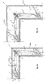
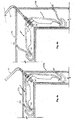
- This configuration of the upwardly bent sides 23 in combination with the sloped platforms 22 defines on either side of base portion 2 sockets being adapted to receive the correspondingly bent flat surfaces 12 followed by the terminal upwardly bent parts 13 of the sheet metal mobile portion 1, 1' as illustratively shown in the sectional views of Figures 3a, 3b , and of Figures 4a, 4b respectively presenting the joint of the aforementioned first and second embodiment of the invention within the receiving chambers of a pair of hollow profile members in a position prior to the initiation of the process of angular connection thereof ( Figs. 3a, 3b ) and in a position following completion of the process of angular connection thereof through a screwing operation of bolt 5 with the Allen key 51 illustrated therein ( Figs. 4a, 4b ).
- the aforementioned upwardly bent terminal parts 13 of the sheet metal mobile portion 1 or 13-14-15 of the sheet metal mobile portion 1' respectively have a length such that, as shown in Figures 3a and 3b , the joint of the invention may be inserted within the adjacent chambers 53a and 53b of the hollow profile members 50 being brought in matching contact without its insertion being impeded by impact of the ends thereof onto the walls of chambers 53a, 53b.
- a single hole is required for the passage of the bolt 5 being driven through introduction of the Allen key 51 in the cavity 5a thereof in the process of use of the joint of the invention and this is an important advantage over the multiple precisely opened holes which are required when joints of the prior art are used as described hereinabove.
- This single hole is conveniently and handily marked and opened to comprise one half hole 51a medially along the edge of chamber 53a and another half hole 51b medially along the edge of chamber 53b, so that when the pair of hollow profile members 50 are brought in matching contact the single hole 51a-51b is being defined for the passage of the bolt 5 of the joint of the invention.
- Figures 9a, 9b, 9c present varying embodiments of the base portion of the joint, which may be alternatively used to achieve the intended rimpedement of the sharpened edges 16 of the sheet metal mobile portion 1 or 1' in the walls of chambers 53a, 53b of the hollow profiles 50 being connected and implement the intended indentation therein.
- Fig. 9a includes the base portion 2 already described and illustrated in Figs. 1a, 1b and 2
- Fig. 9b presents a base portion 2' that comprises the necessary operating features of an upper base 20 whereupon sits the correspondingly configured upper base 10 of the sheet metal mobile portion 1, 1' and of a medially disposed cavity 20a adapted to receive the nut 4 and of the side parts with the sockets 22, 23 adapted to nest the folded surfaces 12, 13 of the sheet metal mobile portion 1, 1', as well as of the outer planar surfaces 24, 25 adapted to abut the walls of the chambers 53a, 53b of the profiles 50 being connected.
- 9b is characterized in that it comprises a first leg member 26 that extends in the direction of the plane of symmetry xx' beyond the vertex of the angle formed at the intersection of the side surfaces 24, 25 and it further comprises a second and a third leg member 27 and 28 respectively, symmetrically extending on either side of the first leg member 26, such leg members 27, 28 extending perpendicularly from the flat surfaces 24, 25 respectively, whereby leg members 26, 27, 28 advantageously effect raising of the aforementioned operational features of the upper base 20 and of the socket configurations on either side thereof at a higher level, thereby rendering such a base portion 2' suitable for use in combination with a sheet metal mobile portion 1 to serve connection of larger hollow profile members 50 having chambers 53a, 53b with a width within the range of 13-25 mm.
- the standard slide base portion 2 might be employed to serve connection of such profile members by means of lifting it at the desired height through using an additional base raising member 3, which, as illustrated in Figure 9a , is an element with an angular configuration identical to that of the slide base portion 2 with a pair of intersecting sides with outer planar surfaces 34, 35 abutting the walls of the chambers 53a, 53b of the hollow profile members 50 being connected and further comprising a leg member 36 extending along the plane of symmetry xx' from the plane of contact of the aforementioned outer planar surfaces 34, 35, such leg member 36 having a top edge 30 being configured in the shape of an oblique angle adapted to fit within the slight indentation 45 provided along the plane of intersection of the outer planar surfaces 24, 25 of the base 2 or 2'.
- Leg members 37, 38 are provided symmetrically on either side of leg member 36, wherein leg members 37, 38 extend perpendicularly upwardly from the surfaces 34, 35 respectively and their ends are configured in the shape of a platform 32 with a curvilinear lateral edge 33, which is adapted to provide mounting thereupon of the socket 22-23 provided at the sides of the base portion 2 and being adapted to nest the correspondingly bent terminal side parts 12, 13 of the sheet metal mobile portion 1, 1'.
- a similarly configured additional base raising member 3 may be employed to provide raising of the slide base portion 2', however without the platforms 32 with the curvilinear lateral edge 33 at the ends of the aforementioned leg members 37, 38, but with these leg members 37, 38 appropriately abutting the outer planar surfaces 24, 25 of the slide base portion 2'.
- Figure 9c shows a further embodiment of a base portion 2" of the joint of the invention, which uses a slide base portion of the type used in conjunction with a mechanical press apparatus, wherein the abovementioned base portion 2" comprises a flat base 20 centrally located at the region of the plane of convergence of the hollow profile members being connected, i.e.
- this base portion 2 extends at side members 41, 42 appropriately sized so as to fit into the chambers 53a and 53b respectively of the hollow profile members being connected.
- Recesses 43 and 44 are respectively provided transversally along the surfaces of side members 41, 42, such recesses 43, 44 being adapted to receive strips being cut through cutting blades being applied exteriorly of the hollow profile members 50 by the mechanical press assembly being employed, such strips being embedded within the recesses 43, 44 thereby optionally offering stabilization of side members 41, 42 of the joint in addition to the indentation of the edges of the sheet metal mobile portion 1, 1' into the walls of chambers 53a, 53b. Further to the above, it is still possible to optionally use an adhesive to enhance stabilization of side members 41, 42 within the chambers 53a, 53b of the hollow profile members being connected. Whilst use of the process of embedding the above strips within the recesses 43, 44 in the slide base portion of the invention is to be considered merely supplementary and optional, it is a necessary requirement in joints of this type used in the prior art.
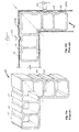
- Figure 11a shows a joint 40 of hollow profile members of the prior art comprising orthogonally oriented side members 41, 42 with appropriately arranged recesses 43, 44 respectively, such side members 41, 42 being respectively inserted within the chambers 53a, 53b of the profile members and such joint 40 being employed in association with a mechanical press apparatus being provided with cutting blades 54, 55, such cutting blades 54, 55 being disposed proximate to the recesses 43, 44 of side members 41, 42 respectively ( Fig. 11b ), whereby they are adapted to cut strips of material of the walls of chambers 53a, 53b respectively and push such strips within the recesses 43, 44, thereby stabilizing joint 40 and effecting a firm connection of the orthogonally abutting hollow profile members 50. Stabilization of the connection may be further enhanced through use of an adhesive matter for previously gluing the side members 41, 42 within the chambers 53a, 53b.
- Figures 10a-10c are shown in correspondence with the varying embodiments of the firmly mounted base portion 2, 2', 2" depicted in Figs. 9a-9c alternative embodiments of the joint of the invention employing a sheet metal mobile member 1 ( Figs. 10a, 10b ) and a sheet metal mobile member 1' ( Fig. 10c )..
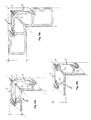
- Figs. 5a and 5b respectively present a detail of the angular joint of the aforementioned first and second embodiment of the invention wherein use is made of the sheet metal mobile portion 1 and 1' adapted to indent a wall of the chamber 53a of hollow profile members having a width within a range of 10-12 mm and within a range of 13-25 mm respectively.
- the detail being depicted in Figs. 5a , 5b is focused on the region of indentation by the sheet metal mobile portion of the wall of the chamber 53a and it is apparent that a proper orientation of the sheet metal mobile portion has been accomplished, this orientation conforming with the abovementioned predetermined geometrical parameters. Contrary to the proper orientation of the sheet metal mobile portion shown in Figs.
- Figs. 6a and 6b show a detail of the joint of the aforementioned first embodiment of the invention as applied within a chamber 53a of a hollow profile member 50 having a width of the order of 25 mm, wherein it is evident that the elongate upwardly extending part of the sheet metal mobile portion 1 is incorrectly oriented and fails to observe the aforementioned predetermined geometrical parameters.
- Fig. 6a apparently shows violation of the limits of the above predetermined geometry with the sheet metal mobile portion impacting onto the wall of chamber 53a at a point along a line determined by an angle (b1), which is drastically reduced in comparison with the desired predetermined parameter of angle (b) that is of the order of 60° as defined hereinabove.
- Fig. 6b also apparently shows violation of the limits of the above predetermined geometry with the angle (a1) having a value substantially higher from the desired predetermined value of angle (a) that is of the order of 45°.
- an object of the present invention is to carry out an appropriate forming of the aberrant terminal edge of the sheet metal portion of the joint of the invention after cutting thereof with a scope of aligning it in the longitudinal direction of the planar sheet metal and of creating a sharpened edge thereof as appropriate for impacting and indenting the wall of the chambers of the hollow profile members being connected.
- Figs. 8a-8c sequentially show the phases of the rimpedement of the sheet metal (SM) that is shown in an enlarged view at a cutting die prior to the action of the cutting blade (CB) thereof ( Fig. 8a ) and of the cutting of a portion (SM1) thereof ( Fig.
- Fig. 8c eventually shows a step in the manufacturing of the sheet metal portion of the joint of the invention that comprises forming of the terminal edge thereof to provide an appropriately sharpened edge configuration 16c.
- Figs. 7a, 7b which show a detail of the joint of the second embodiment of the invention at the point wherein the sheet metal mobile portion 1 impacts onto the wall of the chamber 53a of a hollow profile member and wherein the aberrant sharpened edge 16a produced during cutting of the sheet metal as shown in Fig. 8b , is, as illustrated in Fig. 7a incompatibly and undesirably oriented, thereby failing to achieve an optimum impact of the sheet metal mobile portion 1 or 1' onto the wall of chamber 53a of the profile 50 and to achieve an appropriate indentation thereof.
- the aligned configuration of the terminal edge of the sheet metal portion is not visible to a naked eye, but it is observed as a change in the texture of the surface of the sheet metal portion 1 or 1'.
- the use of the joint of the invention specifies an innovative method of angular connection of a pair of abutting hollow profile members made from aluminium and related materials, the method comprising the following steps:
Landscapes
- Engineering & Computer Science (AREA)
- Civil Engineering (AREA)
- Structural Engineering (AREA)
- Joining Of Corner Units Of Frames Or Wings (AREA)
- Mutual Connection Of Rods And Tubes (AREA)
- Connection Of Plates (AREA)
- Prostheses (AREA)
- Clamps And Clips (AREA)
- Rolls And Other Rotary Bodies (AREA)
Claims (10)
- Verbindung, die zur Winkelverbindung von Hohlprofilelementen (50) angepasst ist, die zum Herstellen von Tür- / Fensterprofilrahmen und dergleichen bestimmt ist, wobei die Kanten der Hohlprofilelementen (50) zuvor in einem Winkel geschnitten wurden, so daß eine entsprechende Kontaktanpassung während deren Montage entlang einer Symmetrieebene (xx') erreichbar sein kann, welche durch die entsprechende Kontaktanpassungsebene der zuvor geschnittenen Kanten der besagten Hohlprofilelementen (50) läuft, wobei die Verbindung umfasst:einen Gleitbasisabschnitt (2, 2', 2"), welcher eine Winkelkonfiguration hat, die entsprechend einer Kante ist, die zwischen einem Paar von miteinander verbundenen Hohlprofilelementen (50) gebildet wird, mit einem oberen ersten Sitz (20) mit einem zentral eingesetzten Hohlraum (20a), und mit den ersten Seitenabschnitten, die sich beiderseits des besagten ersten Sitzes (20) erstrecken, wobei jede der besagten ersten Seitenabschnitten einen ersten Teil (21) umfassen, der sich in einem geneigten nach oben zweiten Teil (22) erstreckt, wobei jeder der besagten ersten Seitenabschnitten flache Außenseiten (25, 26) hat, die in der Lage sind, in einem Gleitkontakt mit einer Wand eines Kammerpaares (53a, 53b) von Hohlprofilelementen (50), die zusammen für die Verbindung gebracht werden, zu kommen,einen beweglichen Metallplattenabschnitt (1, 1'), welcher eine Konfiguration ähnlich mit dem besagten Gleitbasisabschnitt (2, 2', 2") hat, mit einer oberen zweiten Basis (10) mit einer zentral orientiert durchgehenden Öffnung (10a) und mit den zweiten Seitenabschnitten, die sich symmetrisch beiderseits der besagten zweiten Basis (10) erstrecken, wobei jeder der besagten zweiten Seitenabschnitten eine erste flache Seitenfläche (11) umfasst, welche sich zu einer nach innen gebogenen zweiten flachen Seitenfläche (12) erstreckt, die besagte erste flache Seitenfläche (11) mit einer Länge, die im Allgemeinen gleichwertig mit der Länge des untergebenen entsprechenden besagten ersten Teiles (21) ist, und die besagte nach innen gebogene zweite flache Seitenfläche (12) mit einer Länge, die im Allgemeinen gleichwertig mit der Länge des untergebenen entsprechenden zweiten geneigten nach oben Teiles (22) des besagten Gleitbasisabschnitts (2, 2', 2") ist, wobei die besagte zweite flache Seitenfläche (12) sich zu einer nach oben gebogenen Terminal-Seitenfläche (13) erstreckt, welche in einer Richtung parallel zur Symmetrieebene (xx') orientiert wird und endet an scharfen Kanten (16), wobei die besagten scharfen Kanten (16) so angepasst sind, damit sie das Resultat einer bildungsfähigen Vertiefung innerhalb der Kammerwänden (53a, 53b) erzeugen können, wobei der besagte bewegliche Metallplattenabschnitt (1, 1') auf dem besagten Gleitbasisabschnitt (2, 2', 2") eingesetzt wird, so dass die besagte zweite Basis (10) parallel über die untergebene besagte erste Basis (20) orientiert werden kann, wobei die besagten erste und zweite seitliche Abschnitte symmetrisch beiderseits einer Symmetrieebene (xx'), die der flachen entsprechenden Kontaktanpassung der zuvor abgeschnittenen Kanten der besagten Hohlprofilelementen (50) durchlaufen, angeordnet werden undeine Schraube- und Schraubenmutteranordnung, die in einem Festziehungsprozess der Verbindung verwendet wird, wobei die besagte Schraube- und Schraubenmutteranordnung eine Schraubenmutter (4) umfasst, welche innerhalb des besagten zentral orientierten Hohlraumes (20a) des besagten Gleitbasisabschnitts angepasst ist, (2, 2', 2") und eine Schraube (5), die so angeordnet ist, damit sie durch ein Öffnung (51a, 51b) der Hohlprofilelementen (50) durchlaufen kann, welche sich in der besagten Symmetrieebene (xx') befinden, und durch die durchgehende Öffnung (10a) des besagten beweglichen Metallplattenabschnittes (1, 1') und mit der Möglichkeit des Verschraubens an der besagten Schraubenmutter (4), damit eine nach oben Druckkraft auf dem besagten beweglichen Metallplattenabschnitt (1, 1') ausgeübt werden kann, um die besagten zweite Seitenflächen (12) auf den besagten zweiten Teil (22) des besagten Gleitbasisabschnitts (2, 2', 2") zum Gleiten aktivieren werden, wo es sich ergibt, daß der besagte bewegliche Metallplattenabschnitt (1, 1') angehoben werden kann, bis seine besagten scharfen Kanten (16) eine Vertiefung innerhalb der Kammerwänden (53a, 53b) der miteinander verbundenen Hohlprofilelementen (50) bilden können, dadurch gekennzeichnet, dass:
wobei der besagte zweite Teil (22) des besagten Gleitbasisabschnitts (2, 2', 2") zu einer nach oben gebogenen Terminal-Seitenfläche (23) erstreckt, welche in einer Richtung parallel zur Symmetrieebene (xx') angeordnet ist, wobei der besagte zweite Teil (22) und die besagte nach oben gebogene Terminal-Seitenfläche (23 eine Aufnahme (22-23)) definieren, wobei die besagte zweite Seitenfläche (12) und die nach oben gebogene Terminal-Seitenfläche (13) beiderseits des besagten beweglichen Metallplattenabschnittes (1, 1') lassen sich innerhalb der besagten Aufnahme (22-23) beiderseits des besagten Gleitbasisabschnitts (2, 2', 2") einnisten, jede der besagten scharfen Kanten (16) des besagten beweglichen Metallplattenabschnitts (1, 1') eine geschärfte Kante (16c) umfasst, die so angepasst ist, daß sie in Kontakt für die Erzeugung eines Resultates einer bildfähigen Vertiefung in den Kammerwänden (53a, 53b) kommen kann, wobei die besagte geschärfte Kante (16c) durch die Ausrichtung entlang der Richtung der besagten Metallplatte (1, 1') einer abgelenkten scharfen Kante (16a) gebildet wird, die sich als Ergebnis eines Schneidmessers ergibt, welches senkrecht zu einer Metallplattengewebe gerichtet ist, die für die Konstruktion des besagten beweglichen Metallplattenabschnitts (1, 1') verwendet wird, wobei die besagte geschärfte Kante einen scharfen Punkt umfasst, der in der Richtung hinausstreckt, während der bewegliche Metallplattenabschnitt (1, 1') an den Wänden der Kammern (53a, 53b) von Hohlprofilelementen (50) gedrückt wird.
Der besagte bewegliche Metallplattenabschnitt (1, 1') eine Struktur hat, die mit den folgenden gesamten geometrischen Parametern kompatibel ist, solange der innerhalb der Hohlprofilelemente in Position-Stelle liegt:• ein Winkel (a), der von jeden der besagten oberen gebogenen Terminal-Seitenflächen (13) des beweglichen Metallplattenabschnitts (1, 1') gebildet wird mit einer entsprechenden Wand von jedem der Kammerpaaren (53a, 53b) der Hohlprofilelementen (50), auf den der besagte Gleitbasisabschnitt (2, 2', 2") sich beruht, einen Mindestwert von 45° aufweist;• ein Winkel (b), der aus einer Wand von jedem der Kammerpaaren (53a, 53b) der Hohlprofilelementen (50) gebildet wird, auf dem der besagte Gleitbasisabschnitt (2, 2', 2") sich beruht, mit der Gerade-Linie, die einem Kontakt- Endpunkt (E1) der nach innen gebogenen besagten zweiten Seitenfläche (12) des beweglichen Metallplattenabschnitts (1, 1') durchläuft mit dem besagten zweiten Teil (22) des besagten Basisabschnitts (2, 2', 2") vor seinem nach oben Biegung, dass einen nach oben Biegungsabschnitt (13) bildet und von einem Anstoß-Endpunkt (E2) der besagten scharfen Kanten (16) des besagten beweglichen Metallplattenabschnitts (1, 1') entsprechend gegen die Wand der Kammern (53a, 53b) der miteinander verbundenen Hohlprofilelementen (50) mit einem Wert von 60° aufweist, und• ein Winkel (c), der aus einer Wand der Kammern (53a, 53b) der Hohlprofilelementen (50) gebildet wird, an den eine Vertiefung von dem beweglichen Metallplattenabschnitt (1, 1') gebildet wird, mit einer Ebene, die quer der besagten scharfen Kante (16) des beweglichen Metallplattenabschnitts (1, 1') abschneidet, einen Preiswert innerhalb eines Preisfeldes von 45° bis 55° und vorzugsweise einen Preiswert von etwa 45° aufweist. - Verbindung zum Winkelverbinden von Hohlprofilelementen (50), welche für die Bildung von Tür- / Fensterprofilrahmen und dergleichen nach Anspruch 1 bestimmt sind, wobei der besagte bewegliche Metallplattenabschnitt (1, 1') ein beweglicher Abschnitt von Metallplatte (1) ist, welche lineare nach oben gebogenen Terminal-Seitenflächen (13) umfasst, wobei der besagte bewegliche Metallplattenabschnitt (1) zum Verbinden von Hohlprofilelementen (50) mit Kammern (53a, 53b), die eine Breite innerhalb eines Preisfeldes von ca. 12 mm haben, verwendet wird.
- Verbindung zum Winkelverbinden von Hohlprofilelementen (50), welche für die Bildung von Tür- / Fensterprofilrahmen und dergleichen nach Anspruch 1 bestimmt sind, wobei der besagte bewegliche Metallplattenabschnitt (1, 1') ein beweglicher Abschnitt von Metallplatte (1') ist, welche lineare nach oben gebogenen Terminal-Seitenflächen (13) umfasst, wobei jede der besagten gebogenen oberen Terminal-Seitenflächen (13) sich zu einer Zick-Zack Erweiterung (14, 15) erstreckt, welche so angepasst ist, um die Anstoßlinie und die Vertiefungsbildung beiderseits der Enden des beweglichen Metallplattenabschnittes (1') in Richtung der Entfernung von der Symmetrieebene (xx') umzustellen, wobei die besagte Zick-Zack Erweiterung (14, 15) einen ersten Teil (14) umfasst, der an einem ersten Biegungspunkt angebracht wird, der sich am Ende der besagten oben erstreckenden Terminal-Seitenfläche (23) des besagten Gleitbasisabschnitts (2, 2', 2") befindet, wobei der besagte erste Teil (14) nach außen in einem vorbestimmten Bogen mit Entfernungsrichtung von der Symmetrieebene (xx') biegt und ein zweiter Teil (15), der am Ende eines zweiten Biegungspunktes angebracht wird, der sich an einer Kante des nach außen gebogenen besagten ersten Teiles (14) befindet, wobei der besagte zweite Teil (15) nach innen zu einem gleichwertigen mit dem besagten vorbestimmten Bogen mit einer Annäherungsrichtung der Symmetrieebene (xx') biegt, wobei der besagte bewegliche Metallplattenabschnitt (1') zum Verbinden von Hohlprofilelementen verwendet wird (50) mit Kammern (53a, 53b), die Breite innerhalb eines Preisfeldes von 13-25 mm .
- Verbindung zum Winkelverbinden von Hohlprofilelementen (50), welche für die Bildung von Tür- / Fensterprofilrahmen und dergleichen nach Anspruch 1 bestimmt sind, wobei der besagte Gleitbasisabschnitt (2, 2', 2") die besagte obere erste Basis (20) mit einer Morphologie von stumpfer Winkel umfasst und der besagte bewegliche Metallplattenabschnitt (1, 1') die besagte obere zweite Basis (10) mit einer Morphologie von entsprechendem stumpfen Winkel umfasst, der so angepasst ist, damit der auf die besagte obere erste Basis (20) des besagten Gleitbasisabschnittes (2, 2', 2") eingesetzt werden kann, wobei die besagten ersten Seitenteile flache Außenflächen (24, 25) haben, die die Möglichkeit haben in Gleitkontakt mit einer Wand eines Kammerpaares (53a, 53b), das zusammen zur Verbindung mit den Hohlprofilelementen (50) gebracht werden, zu kommen, wobei die besagten flachen Außenflächen (24, 25) einen Winkel bilden, der entsprechend dem Winkel ist, der zwischen den in Kontakt Hohlprofilelementen (50) entsprechend sind, und sind so angepasst, daß sie gleitend in Kontakt mit den Wänden der entsprechenden Kammern (53a, 53b) der miteinander verbundenen Hohlprofilelementen (50) kommen können, wobei eine leichte Vertiefung (45) an der Spitze der besagten Kante angebracht wird, die von den flachen Außenflächen (24, 25) gebildet wird, wobei die besagte leichte Vertiefung (45) so angepasst wird, daß sie irgendwelche Schwierigkeiten vom Gleitkontakt der besagten flachen Flächen (24,25), die mit den Kammerwänden (53a, 53b) der miteinander verbundenen Hohlprofilelementen (50) in Berührung kommen, verhindern können.
- Verbindung zum Winkelverbinden von Hohlprofilelementen (50), welche für die Bildung von Tür- / Fensterprofilrahmen und dergleichen nach Anspruch 4 bestimmt sind, wobei der besagte Gleitbasisabschnitt (2, 2', 2").) ein Gleitbasisabschnitt (2) ist, welcher übrigens ein zusätzliches Hebungsbasiselement (3) mit einer Winkelkonfiguration gleichwertig der besagten Winkelkonfiguration des besagten Gleisbasisabschnittes (2) umfasst, wobei das besagte zusätzliche Hebungsbasiselement (3) ein Kreuzungsseitenpaar mit flachen Außenflächen (34, 35) umfasst, die den Kammerwänden (53a, 53b) der miteinander verbundenen Hohlprofilelementen (50) berühren, ein über die Kreuzungskante der besagten flachen Außenflächen (34, 35) erstreckender Fußstengel (36) entlang der Symmetrieebene (xx'), wobei der besagte Fußstengel (36) eine Spitzenkante (30) hat, die in einer stumpfen Winkelform gebildet ist, damit sie innerhalb der besagten leichten Vertiefung (45), die entlang der Kreuzungslinie der beiderseits des Basisteiles (2), der besagten flachen Außenflächen (24, 25) gebildet ist, angewendet werden kann, und Fußstengeln (37, 38), die symmetrisch beiderseits des besagten Fußstengels (36) senkrecht erstreckend nach oben von den besagten flachen Außenflächen (34, 35 entsprechend) angebracht werden und mit einer Plattform (32) versehen, die sich zu einer krummlinigen quere Kante (33) an der Spitze erstreckt, wobei die besagte Plattform (32) und ihre krummlinige quere Kante (33) so angepasst ist, dass sie an beiden Seiten des Basisabschnitts (2) der besagten Aufnahmen (22, 23) Stützung (23) gewähren kann.
- Verbindung zum Winkelverbinden von Hohlprofilelementen (50), welche für die Bildung von Tür- / Fensterprofilrahmen und dergleichen nach Anspruch 1 bestimmt sind, wobei der besagte Gleitbasisabschnitt (2, 2', 2") ein gleitender Basisabschnitt (2') mit einer Winkelmorphologie ist, die einem Winkel entspricht, der zwischen einem Paar von miteinander verbundenen Hohlprofilelementen (50) mit flachen Außenflächen (24, 25) gebildet wird, einschließlich der besagten leichten Vertiefung (45) in einem Kreuzungsbereich mit einem oberen ersten Sitz (20) mit einem zentral eingesetzten Hohlraum (20a) anpassend, um die besagte Schraubenmutter (4) zu stützen und mit Aufnahmen (22, 23), die sich symmetrisch beiderseits der besagten ersten Basis (20) erstrecken, anpassend um Aufnahmens-Nest der besagten zweiten flachen Seitenfläche (12) und der besagten nach oben gebogenen Terminal-Seitenfläche (13) beiderseits des beweglichen Abschnitts (1, 1') zu gewähren, wobei der besagte Gleitbasisabschnitt (2') übrigens ein Fußstengel (26) umfasst, der sich über die Kreuzungskante der besagten flachen Außenflächen (24, 25) erstreckt und mit der besagten ersten Basis (20) an seiner Spitze versehen ist und die Fußstengeln (27, 28), die symmetrisch beiderseits des besagten Fußstengels (26) gewährt werden, die besagten Fußstengeln (27, 28) erstreckend senkrecht nach oben von den flachen Außenflächen (24, 25) entsprechend und mit den besagten Aufnahmen(22,23) in der Spitze versehen.
- Verbindung zum Winkelverbinden von Hohlprofilelementen (50), welche für die Bildung von Tür- / Fensterprofilrahmen und dergleichen nach Anspruch 6 bestimmt sind, wobei übrigens ein zusätzliches Hebungs-Basiselement (3) mit einer Winkelkonfiguration gleichwertig mit der besagten Winkelkonfiguration des besagten Gleitbasisabschnitts (2')umfasst, wobei das zusätzliche Hebungs-Basiselement (3) ein Kreuzungsseitenpaar mit flachen Außenflächen (34, 35) umfasst, die den Kammerwänden (53a, 53b) der miteinander verbundenen Hohlprofilelementen (50) berühren, ein Fußstengel (36) erstreckend über die Kreuzungskante der besagten flachen Außenflächen (34, 35) entlang der Symmetrieebene (xx'), wobei der besagte Fußstengel (36) eine Spitzenkante (30) hat, die in einer stumpfen Winkelform geformt ist, so angepasst ist, damit sie innerhalb der besagten leichten Vertiefung (45) angewendet werden kann, welche entlang der Kreuzungsebene der angebrachten beiderseits des Basisabschnittes (2') der besagten flachen Außenflächen (24, 25) gebildet ist und der Fußstengel (37, 38) werden symmetrisch beiderseits dem Fußstengel (36) gewährt, die besagten Fußstengeln (37, 38) erstreckend senkrecht nach oben von den flachen Außenflächen (34, 35) entsprechen und berührend an den besagten flachen Außenflächen (24, 25) des besagten Gleitbasisabschnittes (2').
- Verbindung zum Winkelverbinden von Hohlprofilelementen (50), welche für die Bildung von Tür- / Fensterprofilrahmen und dergleichen nach Anspruch 1 bestimmt sind, wobei der besagte Gleitbasisabschnitt (2, 2', 2") ein Gleitbasisabschnitt (2") mit einer Winkelmorphologie ist, die einem Winkel entsprechend ist, der zwischen einem Paar von miteinander verbundenen Hohlprofilelementen (50) gebildet ist, wobei der besagte Gleitbasisabschnitt (2") eine obere erste Basis (20) und Aufnahmen umfasst (22-23), die sich symmetrisch auf beiden Seiten der besagten ersten Basis (20) erstrecken, und so angepasst werden, um ein Nest der besagten zweiten flachen Seitenfläche (12) und der nach oben gebogenen Terminal-Seitenfläche (13) auf beiden Seiten des besagten beweglichen Abschnitts (1, 1') über und auf dem besagten Gleitbasisabschnitt (2') zu gewähren, wobei der besagte Gleitbasisabschnitt (2') sich in seitlichen Stengeln (41, 42) erstreckt, die so gebildet sind, dass sie innerhalb den Kammern (53a) und (53b) entsprechend der miteinander verbundenen Hohlprofilelementen angepasst werden können, wo quer entlang der Flächenstengeln (41) und (42) werden entsprechend Hohlräume (43, 44) versehen, wobei die besagte Hohlräume (43, 44) fakultativ angepasst werden, um Materialstreifen von den Kammerwänden (53a, 53b) entsprechend aufzunehmen, welche von Schneidklingen geschnitten werden, die außerhalb der Hohlprofilräumen (50) angewendet werden, wobei die besagten Streifen innerhalb der Hohlräumen (43, 44) fakultativ eingeführt werden, und auf diese Weise die Stabilisierung der besagten seitlichen Stengeln (41, 42) innerhalb der Kammern (53a, 53b) der miteinander verbundenen Profilen (50) verstärken, zusätzlich durch den besagten scharfen Kanten des beweglichen Metallplattenabschnitts (1, 1') werden Vertiefungen in den Kammerwänden (53a, 53b) gebildet.
- Verbindung zum Winkelverbinden von Hohlprofilelementen (50), welche für die Bildung von Tür- / Fensterprofilrahmen und dergleichen nach Anspruch 1 bestimmt sind, wobei die besagte entlang der besagten Symmetrieebene (xx) gewährte Öffnung (51a, b) der Hohlprofilelementen (50) und zur Aufnahme eines Allen-Shlüßels (51) angebracht, der zum Festziehen-Prozeß der Schraube (5) verwendet wird, eine erste halbe Öffnung (51a) in der Mitte entlang einer ersten Kante einer Kammer (53a) und ein zweite halbe Öffnung (51b) in der Mitte entlang einer zweiten Kante einer Kammer (53b) umfasst.
- Verwendungsmethode der Verbindung nach Anspruch 1 zum Winkelverbinden von Hohlprofilelementen (50), welche zur Bildung von Tür- / Fensterprofilen und dergleichen bestimmt sind, wobei die Methode folgenden Schritte umfasst:a. Schneiden der Kanten, die zur Winkelverbindung der Hohlprofilelementen (50) in einem Winkel mit dem halben Wert ihrer beabsichtigten Winkelverbindung geführt werden, wobei eine Symmetrieebene (xx') die durch eine entsprechende Kontaktebene der miteinander verbundenen besagten Hohlprofilelementen (50) durchläuft und eine Bohrung einer Öffnung (51a, b), welche Öffnung aus eine erste halbe Öffnung (51a) besteht, die zentral entlang einer Kammerkante (53a) einer ersten geführten zum miteinander Verbinden der Hohlprofilelementen (50) angeordnet ist und eine zweite halbe Öffnung (51b), die zentral entlang der Kante einer Kammer (53b) eines zweiten geführten zum Verbinden der Hohlprofilelementen (50) angeordnet ist, wobei die besagte Öffnung (51a, b) so angepasst wird um den Schlüssel (51) aufnehmen zu können, der zum Festziehen einer Schraube (5) verwendet wird, welcher entlang der besagten Symmetrieebene (xx') vorgesehen ist.b. Auswahl der passenden für die Breite der verbundenen Kammern (53a, 53b), von den geführten zur Verbindung der Hohlprofilelementen (50) der Gleitbasisabschnitten (2) oder (2') mit /oder ohne Zusatz eines Hebungsbasiselements (3) oder eines Basisabschnitts (2") in Kombination mit einem Metallplattenabschnitt (1) oder (1') und die Montage der Verbindung mit dem Durchgang der Schrauben (5) durch einer durchgehenden Öffnung (10a) des Metallplattenabschnittes (1) oder (1'); und dessen Verschrauben in dem eingesetzten am Gleitbasisabschnitt( der Schraubenmutter (4),c. Einführung einer ersten Hälfte der montierten Verbindung in die Kammer (53a) der ersten von den geführten zur Verbindung der Hohlprofilelementen (50),d. Bringung der Kammer (53b) des zweiten von den geführten zur Verbindung des Hohlprofilelements (50) in den entsprechenden Kontakt mit der Kammer (53a) des ersten von den geführten zur Verbindung des Hohlprofilelements (50) und die Einführung der zweiten vorstehenden von der Kammer (53a) der Hälfte der montierten Verbindung in die Kammer (53b), so daß ein Zusammentreffen des besagten ersten und des zweiten Hohlprofilelements (50) ergeben kann und eine Bildung der Öffnung (51a, b) mit dem Kontakt der entsprechenden Hälften der Öffnung (51a, 51b).e. Einführung des Schlüssels (51) durch die Öffnung (51a, b) und dessen Umdrehung für die Festziehung der Schraube (5) mit Verschrauben innerhalb der Schraubenmutter (4) bis ein Anstoß und eine Einkeilung der besagten nach oben gebogenen Schenkeln (13) des beweglichen Metallplattenabschnittes (1) oder der besagten gebogenen nach oben Schenkeln (13-14-15) des Metallplattenabschnitts (1') an den Kammerwänden (53a, 53b) ergeben wird, wodurch eine stabile Verbindung der Hohlprofilelementen (50) und eine Ausrichtung der Verbindung aufgrund der symmetrischen Orientierung beiderseits der Symmetrieebene (xx) gewähren werden kann.
Applications Claiming Priority (2)
| Application Number | Priority Date | Filing Date | Title |
|---|---|---|---|
| GR20150100500A GR1009147B (el) | 2015-11-18 | 2015-11-18 | Γωνιακος συνδεσμος ζευγους προφιλ αλουμινιου και συναφων υλικων |
| PCT/GR2016/000062 WO2017085521A1 (en) | 2015-11-18 | 2016-11-18 | Joint for the angular connection of hollow profile members and method using such joint |
Publications (2)
| Publication Number | Publication Date |
|---|---|
| EP3377720A1 EP3377720A1 (de) | 2018-09-26 |
| EP3377720B1 true EP3377720B1 (de) | 2020-03-25 |
Family
ID=57794305
Family Applications (1)
| Application Number | Title | Priority Date | Filing Date |
|---|---|---|---|
| EP16825876.2A Active EP3377720B1 (de) | 2015-11-18 | 2016-11-18 | Verbindungsstück für winkelverbindung von hohlprofilelementen und verfahren unter verwendung eines derartigen verbindungsstückes |
Country Status (7)
| Country | Link |
|---|---|
| US (1) | US10619405B2 (de) |
| EP (1) | EP3377720B1 (de) |
| ES (1) | ES2801651T3 (de) |
| GR (1) | GR1009147B (de) |
| IL (1) | IL259465B (de) |
| SG (1) | SG11201804176VA (de) |
| WO (1) | WO2017085521A1 (de) |
Families Citing this family (7)
| Publication number | Priority date | Publication date | Assignee | Title |
|---|---|---|---|---|
| GB2576731B (en) * | 2018-08-29 | 2022-06-15 | Aanco Uk Ltd | Frame connector |
| US11078720B2 (en) * | 2019-05-09 | 2021-08-03 | Amesbury Group, Inc. | Corner key for extruded windows and doors |
| USD909855S1 (en) | 2019-05-09 | 2021-02-09 | Amesbury Group, Inc. | Corner key |
| USD988838S1 (en) * | 2021-06-18 | 2023-06-13 | Chiao-Yin CHANG | Corner bracket |
| CN113585917A (zh) * | 2021-09-06 | 2021-11-02 | 宁波腾宇金属制品有限公司 | 一种组装式门框 |
| US12188228B2 (en) * | 2022-04-01 | 2025-01-07 | Herman Miller Limited | Screen and frame for the same |
| CN114525994B (zh) * | 2022-04-01 | 2024-06-21 | 广东欧派克家居智能科技有限公司 | 一种快装门窗系统及其安装方法 |
Family Cites Families (15)
| Publication number | Priority date | Publication date | Assignee | Title |
|---|---|---|---|---|
| US3782054A (en) * | 1971-09-15 | 1974-01-01 | Capitol Prod Corp | Corner angle for windows |
| US3848390A (en) * | 1973-01-12 | 1974-11-19 | United States Banknote Corp | Window fastener |
| NO137513C (no) * | 1974-01-29 | 1978-03-08 | Raufoss Ammunisjonsfabrikker | Sammenfoeyningselement. |
| DE2706379C2 (de) * | 1977-01-28 | 1982-06-09 | Technal International S.A., Toulouse | Verbindungsorgan zum Herstellen einer Winkelverbindung zwischen zwei auf Gehrung geschnittenen Profilen |
| ZA757904B (en) * | 1975-12-18 | 1977-05-25 | H Bub | Fastening means |
| FR2429350A1 (fr) * | 1978-06-21 | 1980-01-18 | Sodial | Dispositif d'assemblage de profiles tubulaires |
| FR2562173B1 (fr) * | 1984-03-28 | 1986-08-14 | Maier Ets | Equerre de liaison pour realiser l'assemblage de deux profiles |
| FR2594905B1 (fr) * | 1986-02-24 | 1988-06-24 | Technal Snc | Piece de jonction permettant d'assembler par rapprochement deux profiles tubulaires coupes a un angle donne |
| IT230412Y1 (it) * | 1993-09-17 | 1999-06-07 | Alumix Spa | Struttura di collegamento a squadretta per la giunzione ad angolo retto di profilati metallici per infissi, telai e strutture simili |
| GR1002958B (el) * | 1996-07-23 | 1998-09-01 | Μηχανικη γωνια συνδεσης (προφιλ) μεταλλικων κοιλοδοκων. | |
| US7509780B2 (en) * | 2002-10-09 | 2009-03-31 | Athanasios Leontaridis | Joint for the angular connection of door window profile frames and the like |
| GR1004653B (el) * | 2002-10-09 | 2004-08-04 | Γωνιακος συνδεσμος ζευγους προφιλ αλουμινιου και συναφων υλικων | |
| CA2595273A1 (en) * | 2005-01-18 | 2006-07-27 | Karl Lenhardt | Spacer for insulating glass panes and method for the production thereof |
| WO2006076934A1 (de) * | 2005-01-18 | 2006-07-27 | Karl Lenhardt | Isolierglasscheibe mit einem rahmenförmigen abstandhalter |
| FR2904068A1 (fr) * | 2006-07-18 | 2008-01-25 | Norsk Hydro As | Dispositif de liaison entre deux extremites de profiles tubulaires destines a former un assemblage angulaire. |
-
2015
- 2015-11-18 GR GR20150100500A patent/GR1009147B/el active IP Right Grant
-
2016
- 2016-11-18 ES ES16825876T patent/ES2801651T3/es active Active
- 2016-11-18 EP EP16825876.2A patent/EP3377720B1/de active Active
- 2016-11-18 US US15/777,046 patent/US10619405B2/en active Active
- 2016-11-18 SG SG11201804176VA patent/SG11201804176VA/en unknown
- 2016-11-18 WO PCT/GR2016/000062 patent/WO2017085521A1/en not_active Ceased
-
2018
- 2018-05-17 IL IL259465A patent/IL259465B/en active IP Right Grant
Non-Patent Citations (1)
| Title |
|---|
| None * |
Also Published As
| Publication number | Publication date |
|---|---|
| US10619405B2 (en) | 2020-04-14 |
| EP3377720A1 (de) | 2018-09-26 |
| WO2017085521A1 (en) | 2017-05-26 |
| ES2801651T3 (es) | 2021-01-12 |
| US20180334848A1 (en) | 2018-11-22 |
| SG11201804176VA (en) | 2018-06-28 |
| IL259465A (en) | 2018-07-31 |
| IL259465B (en) | 2021-06-30 |
| GR20150100500A (el) | 2017-08-04 |
| GR1009147B (el) | 2017-10-30 |
Similar Documents
| Publication | Publication Date | Title |
|---|---|---|
| EP3377720B1 (de) | Verbindungsstück für winkelverbindung von hohlprofilelementen und verfahren unter verwendung eines derartigen verbindungsstückes | |
| US20160069088A1 (en) | Method for producing a mechanical locking system for building panels | |
| US9410360B2 (en) | Door assembly | |
| US20100003077A1 (en) | Apparatus and Method for Assembling Structural Components | |
| EP1718812B1 (de) | Vorrichtung zur verbindung von konstruktionselementen | |
| AU2017222476B2 (en) | Structure with hollow or partially hollow structural elements, with modular and improved system of joints | |
| CA2814522A1 (en) | Apparatus and method for connecting a rail or structural member to a post or other structure | |
| EP2072727A1 (de) | Scharnier für eine Metalltür oder für Fenstereinheiten | |
| US7509780B2 (en) | Joint for the angular connection of door window profile frames and the like | |
| IT202000013438A1 (it) | Sistema di giunzione tra componenti di un mobile e mobile comprendente detto sistema | |
| KR20090003586U (ko) | 건축용 판넬 및 이의 시공장치 | |
| CN200996246Y (zh) | 一种平开房门及铰接构件 | |
| US20030046881A1 (en) | Standardized arched jamb assembly and method | |
| EP1567743B1 (de) | Eckverbindungsvorrichtung für fenster- oder türprofilrahmen | |
| KR200446329Y1 (ko) | 행거용 u채널 연결구 | |
| KR20160146165A (ko) | 중공문짝의 조립방법 및 이에 따라 조립되는 중공문짝 | |
| US20120198786A1 (en) | Door corner assembly | |
| CN218093782U (zh) | 一种卡接件、连接件及连接组件 | |
| EP1424464A2 (de) | Verbindungselement insbesondere für Hohlprofile | |
| JP4765102B2 (ja) | サッシ窓 | |
| KR200246602Y1 (ko) | 문짝설치용 문틀 조립구조 | |
| EP2975206A1 (de) | Verstärktes profil für schieberahmen und satz aus profilen für fensterrahmen und schieberahmen | |
| CN208905459U (zh) | 一种结构稳固的厨卫板材 | |
| FR2866054A1 (fr) | Panneau d'element de fermeture realise par assemblage de lames. | |
| EP1122392A2 (de) | Rahmensystem |
Legal Events
| Date | Code | Title | Description |
|---|---|---|---|
| STAA | Information on the status of an ep patent application or granted ep patent |
Free format text: STATUS: UNKNOWN |
|
| STAA | Information on the status of an ep patent application or granted ep patent |
Free format text: STATUS: THE INTERNATIONAL PUBLICATION HAS BEEN MADE |
|
| PUAI | Public reference made under article 153(3) epc to a published international application that has entered the european phase |
Free format text: ORIGINAL CODE: 0009012 |
|
| STAA | Information on the status of an ep patent application or granted ep patent |
Free format text: STATUS: REQUEST FOR EXAMINATION WAS MADE |
|
| 17P | Request for examination filed |
Effective date: 20180618 |
|
| AK | Designated contracting states |
Kind code of ref document: A1 Designated state(s): AL AT BE BG CH CY CZ DE DK EE ES FI FR GB GR HR HU IE IS IT LI LT LU LV MC MK MT NL NO PL PT RO RS SE SI SK SM TR |
|
| AX | Request for extension of the european patent |
Extension state: BA ME |
|
| DAV | Request for validation of the european patent (deleted) | ||
| DAX | Request for extension of the european patent (deleted) | ||
| GRAP | Despatch of communication of intention to grant a patent |
Free format text: ORIGINAL CODE: EPIDOSNIGR1 |
|
| STAA | Information on the status of an ep patent application or granted ep patent |
Free format text: STATUS: GRANT OF PATENT IS INTENDED |
|
| INTG | Intention to grant announced |
Effective date: 20191010 |
|
| GRAS | Grant fee paid |
Free format text: ORIGINAL CODE: EPIDOSNIGR3 |
|
| GRAA | (expected) grant |
Free format text: ORIGINAL CODE: 0009210 |
|
| STAA | Information on the status of an ep patent application or granted ep patent |
Free format text: STATUS: THE PATENT HAS BEEN GRANTED |
|
| AK | Designated contracting states |
Kind code of ref document: B1 Designated state(s): AL AT BE BG CH CY CZ DE DK EE ES FI FR GB GR HR HU IE IS IT LI LT LU LV MC MK MT NL NO PL PT RO RS SE SI SK SM TR |
|
| REG | Reference to a national code |
Ref country code: GB Ref legal event code: FG4D |
|
| REG | Reference to a national code |
Ref country code: DE Ref legal event code: R096 Ref document number: 602016032693 Country of ref document: DE |
|
| REG | Reference to a national code |
Ref country code: AT Ref legal event code: REF Ref document number: 1248758 Country of ref document: AT Kind code of ref document: T Effective date: 20200415 Ref country code: IE Ref legal event code: FG4D |
|
| PG25 | Lapsed in a contracting state [announced via postgrant information from national office to epo] |
Ref country code: NO Free format text: LAPSE BECAUSE OF FAILURE TO SUBMIT A TRANSLATION OF THE DESCRIPTION OR TO PAY THE FEE WITHIN THE PRESCRIBED TIME-LIMIT Effective date: 20200625 Ref country code: RS Free format text: LAPSE BECAUSE OF FAILURE TO SUBMIT A TRANSLATION OF THE DESCRIPTION OR TO PAY THE FEE WITHIN THE PRESCRIBED TIME-LIMIT Effective date: 20200325 Ref country code: FI Free format text: LAPSE BECAUSE OF FAILURE TO SUBMIT A TRANSLATION OF THE DESCRIPTION OR TO PAY THE FEE WITHIN THE PRESCRIBED TIME-LIMIT Effective date: 20200325 |
|
| REG | Reference to a national code |
Ref country code: NL Ref legal event code: FP |
|
| PG25 | Lapsed in a contracting state [announced via postgrant information from national office to epo] |
Ref country code: GR Free format text: LAPSE BECAUSE OF FAILURE TO SUBMIT A TRANSLATION OF THE DESCRIPTION OR TO PAY THE FEE WITHIN THE PRESCRIBED TIME-LIMIT Effective date: 20200626 Ref country code: BG Free format text: LAPSE BECAUSE OF FAILURE TO SUBMIT A TRANSLATION OF THE DESCRIPTION OR TO PAY THE FEE WITHIN THE PRESCRIBED TIME-LIMIT Effective date: 20200625 Ref country code: HR Free format text: LAPSE BECAUSE OF FAILURE TO SUBMIT A TRANSLATION OF THE DESCRIPTION OR TO PAY THE FEE WITHIN THE PRESCRIBED TIME-LIMIT Effective date: 20200325 Ref country code: LV Free format text: LAPSE BECAUSE OF FAILURE TO SUBMIT A TRANSLATION OF THE DESCRIPTION OR TO PAY THE FEE WITHIN THE PRESCRIBED TIME-LIMIT Effective date: 20200325 Ref country code: SE Free format text: LAPSE BECAUSE OF FAILURE TO SUBMIT A TRANSLATION OF THE DESCRIPTION OR TO PAY THE FEE WITHIN THE PRESCRIBED TIME-LIMIT Effective date: 20200325 |
|
| REG | Reference to a national code |
Ref country code: LT Ref legal event code: MG4D |
|
| PG25 | Lapsed in a contracting state [announced via postgrant information from national office to epo] |
Ref country code: SM Free format text: LAPSE BECAUSE OF FAILURE TO SUBMIT A TRANSLATION OF THE DESCRIPTION OR TO PAY THE FEE WITHIN THE PRESCRIBED TIME-LIMIT Effective date: 20200325 Ref country code: LT Free format text: LAPSE BECAUSE OF FAILURE TO SUBMIT A TRANSLATION OF THE DESCRIPTION OR TO PAY THE FEE WITHIN THE PRESCRIBED TIME-LIMIT Effective date: 20200325 Ref country code: CZ Free format text: LAPSE BECAUSE OF FAILURE TO SUBMIT A TRANSLATION OF THE DESCRIPTION OR TO PAY THE FEE WITHIN THE PRESCRIBED TIME-LIMIT Effective date: 20200325 Ref country code: RO Free format text: LAPSE BECAUSE OF FAILURE TO SUBMIT A TRANSLATION OF THE DESCRIPTION OR TO PAY THE FEE WITHIN THE PRESCRIBED TIME-LIMIT Effective date: 20200325 Ref country code: EE Free format text: LAPSE BECAUSE OF FAILURE TO SUBMIT A TRANSLATION OF THE DESCRIPTION OR TO PAY THE FEE WITHIN THE PRESCRIBED TIME-LIMIT Effective date: 20200325 Ref country code: IS Free format text: LAPSE BECAUSE OF FAILURE TO SUBMIT A TRANSLATION OF THE DESCRIPTION OR TO PAY THE FEE WITHIN THE PRESCRIBED TIME-LIMIT Effective date: 20200725 Ref country code: PT Free format text: LAPSE BECAUSE OF FAILURE TO SUBMIT A TRANSLATION OF THE DESCRIPTION OR TO PAY THE FEE WITHIN THE PRESCRIBED TIME-LIMIT Effective date: 20200818 Ref country code: SK Free format text: LAPSE BECAUSE OF FAILURE TO SUBMIT A TRANSLATION OF THE DESCRIPTION OR TO PAY THE FEE WITHIN THE PRESCRIBED TIME-LIMIT Effective date: 20200325 |
|
| REG | Reference to a national code |
Ref country code: AT Ref legal event code: MK05 Ref document number: 1248758 Country of ref document: AT Kind code of ref document: T Effective date: 20200325 |
|
| REG | Reference to a national code |
Ref country code: ES Ref legal event code: FG2A Ref document number: 2801651 Country of ref document: ES Kind code of ref document: T3 Effective date: 20210112 Ref country code: DE Ref legal event code: R097 Ref document number: 602016032693 Country of ref document: DE |
|
| PG25 | Lapsed in a contracting state [announced via postgrant information from national office to epo] |
Ref country code: AT Free format text: LAPSE BECAUSE OF FAILURE TO SUBMIT A TRANSLATION OF THE DESCRIPTION OR TO PAY THE FEE WITHIN THE PRESCRIBED TIME-LIMIT Effective date: 20200325 Ref country code: DK Free format text: LAPSE BECAUSE OF FAILURE TO SUBMIT A TRANSLATION OF THE DESCRIPTION OR TO PAY THE FEE WITHIN THE PRESCRIBED TIME-LIMIT Effective date: 20200325 |
|
| PLBE | No opposition filed within time limit |
Free format text: ORIGINAL CODE: 0009261 |
|
| STAA | Information on the status of an ep patent application or granted ep patent |
Free format text: STATUS: NO OPPOSITION FILED WITHIN TIME LIMIT |
|
| PG25 | Lapsed in a contracting state [announced via postgrant information from national office to epo] |
Ref country code: PL Free format text: LAPSE BECAUSE OF FAILURE TO SUBMIT A TRANSLATION OF THE DESCRIPTION OR TO PAY THE FEE WITHIN THE PRESCRIBED TIME-LIMIT Effective date: 20200325 |
|
| 26N | No opposition filed |
Effective date: 20210112 |
|
| PG25 | Lapsed in a contracting state [announced via postgrant information from national office to epo] |
Ref country code: SI Free format text: LAPSE BECAUSE OF FAILURE TO SUBMIT A TRANSLATION OF THE DESCRIPTION OR TO PAY THE FEE WITHIN THE PRESCRIBED TIME-LIMIT Effective date: 20200325 |
|
| PG25 | Lapsed in a contracting state [announced via postgrant information from national office to epo] |
Ref country code: MC Free format text: LAPSE BECAUSE OF FAILURE TO SUBMIT A TRANSLATION OF THE DESCRIPTION OR TO PAY THE FEE WITHIN THE PRESCRIBED TIME-LIMIT Effective date: 20200325 |
|
| REG | Reference to a national code |
Ref country code: CH Ref legal event code: PL |
|
| PG25 | Lapsed in a contracting state [announced via postgrant information from national office to epo] |
Ref country code: LU Free format text: LAPSE BECAUSE OF NON-PAYMENT OF DUE FEES Effective date: 20201118 |
|
| PG25 | Lapsed in a contracting state [announced via postgrant information from national office to epo] |
Ref country code: LI Free format text: LAPSE BECAUSE OF NON-PAYMENT OF DUE FEES Effective date: 20201130 Ref country code: CH Free format text: LAPSE BECAUSE OF NON-PAYMENT OF DUE FEES Effective date: 20201130 |
|
| PG25 | Lapsed in a contracting state [announced via postgrant information from national office to epo] |
Ref country code: IE Free format text: LAPSE BECAUSE OF NON-PAYMENT OF DUE FEES Effective date: 20201118 |
|
| PG25 | Lapsed in a contracting state [announced via postgrant information from national office to epo] |
Ref country code: MT Free format text: LAPSE BECAUSE OF FAILURE TO SUBMIT A TRANSLATION OF THE DESCRIPTION OR TO PAY THE FEE WITHIN THE PRESCRIBED TIME-LIMIT Effective date: 20200325 Ref country code: CY Free format text: LAPSE BECAUSE OF FAILURE TO SUBMIT A TRANSLATION OF THE DESCRIPTION OR TO PAY THE FEE WITHIN THE PRESCRIBED TIME-LIMIT Effective date: 20200325 |
|
| PG25 | Lapsed in a contracting state [announced via postgrant information from national office to epo] |
Ref country code: MK Free format text: LAPSE BECAUSE OF FAILURE TO SUBMIT A TRANSLATION OF THE DESCRIPTION OR TO PAY THE FEE WITHIN THE PRESCRIBED TIME-LIMIT Effective date: 20200325 Ref country code: AL Free format text: LAPSE BECAUSE OF FAILURE TO SUBMIT A TRANSLATION OF THE DESCRIPTION OR TO PAY THE FEE WITHIN THE PRESCRIBED TIME-LIMIT Effective date: 20200325 |
|
| PGFP | Annual fee paid to national office [announced via postgrant information from national office to epo] |
Ref country code: NL Payment date: 20251122 Year of fee payment: 10 |
|
| PGFP | Annual fee paid to national office [announced via postgrant information from national office to epo] |
Ref country code: DE Payment date: 20251118 Year of fee payment: 10 |
|
| PGFP | Annual fee paid to national office [announced via postgrant information from national office to epo] |
Ref country code: GB Payment date: 20251110 Year of fee payment: 10 |
|
| PGFP | Annual fee paid to national office [announced via postgrant information from national office to epo] |
Ref country code: IT Payment date: 20251118 Year of fee payment: 10 |
|
| PGFP | Annual fee paid to national office [announced via postgrant information from national office to epo] |
Ref country code: FR Payment date: 20251126 Year of fee payment: 10 |
|
| PGFP | Annual fee paid to national office [announced via postgrant information from national office to epo] |
Ref country code: TR Payment date: 20251114 Year of fee payment: 10 Ref country code: BE Payment date: 20251118 Year of fee payment: 10 |
|
| PGFP | Annual fee paid to national office [announced via postgrant information from national office to epo] |
Ref country code: ES Payment date: 20251201 Year of fee payment: 10 |