EP3377759B1 - Commande d'une éolienne à pales de rotor réglables - Google Patents
Commande d'une éolienne à pales de rotor réglables Download PDFInfo
- Publication number
- EP3377759B1 EP3377759B1 EP16797557.2A EP16797557A EP3377759B1 EP 3377759 B1 EP3377759 B1 EP 3377759B1 EP 16797557 A EP16797557 A EP 16797557A EP 3377759 B1 EP3377759 B1 EP 3377759B1
- Authority
- EP
- European Patent Office
- Prior art keywords
- angle
- blade
- partial load
- blade angle
- wind
- Prior art date
- Legal status (The legal status is an assumption and is not a legal conclusion. Google has not performed a legal analysis and makes no representation as to the accuracy of the status listed.)
- Active
Links
Images

Classifications
-
- F—MECHANICAL ENGINEERING; LIGHTING; HEATING; WEAPONS; BLASTING
- F03—MACHINES OR ENGINES FOR LIQUIDS; WIND, SPRING, OR WEIGHT MOTORS; PRODUCING MECHANICAL POWER OR A REACTIVE PROPULSIVE THRUST, NOT OTHERWISE PROVIDED FOR
- F03D—WIND MOTORS
- F03D7/00—Controlling wind motors
- F03D7/02—Controlling wind motors the wind motors having rotation axis substantially parallel to the air flow entering the rotor
- F03D7/022—Adjusting aerodynamic properties of the blades
- F03D7/0224—Adjusting blade pitch
-
- F—MECHANICAL ENGINEERING; LIGHTING; HEATING; WEAPONS; BLASTING
- F03—MACHINES OR ENGINES FOR LIQUIDS; WIND, SPRING, OR WEIGHT MOTORS; PRODUCING MECHANICAL POWER OR A REACTIVE PROPULSIVE THRUST, NOT OTHERWISE PROVIDED FOR
- F03D—WIND MOTORS
- F03D1/00—Wind motors with rotation axis substantially parallel to the air flow entering the rotor
- F03D1/06—Rotors
-
- F—MECHANICAL ENGINEERING; LIGHTING; HEATING; WEAPONS; BLASTING
- F03—MACHINES OR ENGINES FOR LIQUIDS; WIND, SPRING, OR WEIGHT MOTORS; PRODUCING MECHANICAL POWER OR A REACTIVE PROPULSIVE THRUST, NOT OTHERWISE PROVIDED FOR
- F03D—WIND MOTORS
- F03D17/00—Monitoring or testing of wind motors, e.g. diagnostics
-
- F—MECHANICAL ENGINEERING; LIGHTING; HEATING; WEAPONS; BLASTING
- F03—MACHINES OR ENGINES FOR LIQUIDS; WIND, SPRING, OR WEIGHT MOTORS; PRODUCING MECHANICAL POWER OR A REACTIVE PROPULSIVE THRUST, NOT OTHERWISE PROVIDED FOR
- F03D—WIND MOTORS
- F03D7/00—Controlling wind motors
- F03D7/02—Controlling wind motors the wind motors having rotation axis substantially parallel to the air flow entering the rotor
- F03D7/022—Adjusting aerodynamic properties of the blades
- F03D7/024—Adjusting aerodynamic properties of the blades of individual blades
-
- F—MECHANICAL ENGINEERING; LIGHTING; HEATING; WEAPONS; BLASTING
- F03—MACHINES OR ENGINES FOR LIQUIDS; WIND, SPRING, OR WEIGHT MOTORS; PRODUCING MECHANICAL POWER OR A REACTIVE PROPULSIVE THRUST, NOT OTHERWISE PROVIDED FOR
- F03D—WIND MOTORS
- F03D7/00—Controlling wind motors
- F03D7/02—Controlling wind motors the wind motors having rotation axis substantially parallel to the air flow entering the rotor
- F03D7/026—Controlling wind motors the wind motors having rotation axis substantially parallel to the air flow entering the rotor for starting-up
-
- F—MECHANICAL ENGINEERING; LIGHTING; HEATING; WEAPONS; BLASTING
- F05—INDEXING SCHEMES RELATING TO ENGINES OR PUMPS IN VARIOUS SUBCLASSES OF CLASSES F01-F04
- F05B—INDEXING SCHEME RELATING TO WIND, SPRING, WEIGHT, INERTIA OR LIKE MOTORS, TO MACHINES OR ENGINES FOR LIQUIDS COVERED BY SUBCLASSES F03B, F03D AND F03G
- F05B2220/00—Application
- F05B2220/30—Application in turbines
-
- F—MECHANICAL ENGINEERING; LIGHTING; HEATING; WEAPONS; BLASTING
- F05—INDEXING SCHEMES RELATING TO ENGINES OR PUMPS IN VARIOUS SUBCLASSES OF CLASSES F01-F04
- F05B—INDEXING SCHEME RELATING TO WIND, SPRING, WEIGHT, INERTIA OR LIKE MOTORS, TO MACHINES OR ENGINES FOR LIQUIDS COVERED BY SUBCLASSES F03B, F03D AND F03G
- F05B2240/00—Components
- F05B2240/20—Rotors
- F05B2240/21—Rotors for wind turbines
- F05B2240/221—Rotors for wind turbines with horizontal axis
-
- F—MECHANICAL ENGINEERING; LIGHTING; HEATING; WEAPONS; BLASTING
- F05—INDEXING SCHEMES RELATING TO ENGINES OR PUMPS IN VARIOUS SUBCLASSES OF CLASSES F01-F04
- F05B—INDEXING SCHEME RELATING TO WIND, SPRING, WEIGHT, INERTIA OR LIKE MOTORS, TO MACHINES OR ENGINES FOR LIQUIDS COVERED BY SUBCLASSES F03B, F03D AND F03G
- F05B2260/00—Function
- F05B2260/70—Adjusting of angle of incidence or attack of rotating blades
- F05B2260/74—Adjusting of angle of incidence or attack of rotating blades by turning around an axis perpendicular the rotor centre line
-
- F—MECHANICAL ENGINEERING; LIGHTING; HEATING; WEAPONS; BLASTING
- F05—INDEXING SCHEMES RELATING TO ENGINES OR PUMPS IN VARIOUS SUBCLASSES OF CLASSES F01-F04
- F05B—INDEXING SCHEME RELATING TO WIND, SPRING, WEIGHT, INERTIA OR LIKE MOTORS, TO MACHINES OR ENGINES FOR LIQUIDS COVERED BY SUBCLASSES F03B, F03D AND F03G
- F05B2260/00—Function
- F05B2260/83—Testing, e.g. methods, components or tools therefor
-
- F—MECHANICAL ENGINEERING; LIGHTING; HEATING; WEAPONS; BLASTING
- F05—INDEXING SCHEMES RELATING TO ENGINES OR PUMPS IN VARIOUS SUBCLASSES OF CLASSES F01-F04
- F05B—INDEXING SCHEME RELATING TO WIND, SPRING, WEIGHT, INERTIA OR LIKE MOTORS, TO MACHINES OR ENGINES FOR LIQUIDS COVERED BY SUBCLASSES F03B, F03D AND F03G
- F05B2270/00—Control
- F05B2270/10—Purpose of the control system
- F05B2270/103—Purpose of the control system to affect the output of the engine
- F05B2270/1033—Power (if explicitly mentioned)
-
- F—MECHANICAL ENGINEERING; LIGHTING; HEATING; WEAPONS; BLASTING
- F05—INDEXING SCHEMES RELATING TO ENGINES OR PUMPS IN VARIOUS SUBCLASSES OF CLASSES F01-F04
- F05B—INDEXING SCHEME RELATING TO WIND, SPRING, WEIGHT, INERTIA OR LIKE MOTORS, TO MACHINES OR ENGINES FOR LIQUIDS COVERED BY SUBCLASSES F03B, F03D AND F03G
- F05B2270/00—Control
- F05B2270/10—Purpose of the control system
- F05B2270/20—Purpose of the control system to optimise the performance of a machine
-
- F—MECHANICAL ENGINEERING; LIGHTING; HEATING; WEAPONS; BLASTING
- F05—INDEXING SCHEMES RELATING TO ENGINES OR PUMPS IN VARIOUS SUBCLASSES OF CLASSES F01-F04
- F05B—INDEXING SCHEME RELATING TO WIND, SPRING, WEIGHT, INERTIA OR LIKE MOTORS, TO MACHINES OR ENGINES FOR LIQUIDS COVERED BY SUBCLASSES F03B, F03D AND F03G
- F05B2270/00—Control
- F05B2270/30—Control parameters, e.g. input parameters
- F05B2270/309—Rate of change of parameters
-
- F—MECHANICAL ENGINEERING; LIGHTING; HEATING; WEAPONS; BLASTING
- F05—INDEXING SCHEMES RELATING TO ENGINES OR PUMPS IN VARIOUS SUBCLASSES OF CLASSES F01-F04
- F05B—INDEXING SCHEME RELATING TO WIND, SPRING, WEIGHT, INERTIA OR LIKE MOTORS, TO MACHINES OR ENGINES FOR LIQUIDS COVERED BY SUBCLASSES F03B, F03D AND F03G
- F05B2270/00—Control
- F05B2270/30—Control parameters, e.g. input parameters
- F05B2270/32—Wind speeds
-
- F—MECHANICAL ENGINEERING; LIGHTING; HEATING; WEAPONS; BLASTING
- F05—INDEXING SCHEMES RELATING TO ENGINES OR PUMPS IN VARIOUS SUBCLASSES OF CLASSES F01-F04
- F05B—INDEXING SCHEME RELATING TO WIND, SPRING, WEIGHT, INERTIA OR LIKE MOTORS, TO MACHINES OR ENGINES FOR LIQUIDS COVERED BY SUBCLASSES F03B, F03D AND F03G
- F05B2270/00—Control
- F05B2270/30—Control parameters, e.g. input parameters
- F05B2270/322—Control parameters, e.g. input parameters the detection or prediction of a wind gust
-
- F—MECHANICAL ENGINEERING; LIGHTING; HEATING; WEAPONS; BLASTING
- F05—INDEXING SCHEMES RELATING TO ENGINES OR PUMPS IN VARIOUS SUBCLASSES OF CLASSES F01-F04
- F05B—INDEXING SCHEME RELATING TO WIND, SPRING, WEIGHT, INERTIA OR LIKE MOTORS, TO MACHINES OR ENGINES FOR LIQUIDS COVERED BY SUBCLASSES F03B, F03D AND F03G
- F05B2270/00—Control
- F05B2270/30—Control parameters, e.g. input parameters
- F05B2270/327—Rotor or generator speeds
-
- F—MECHANICAL ENGINEERING; LIGHTING; HEATING; WEAPONS; BLASTING
- F05—INDEXING SCHEMES RELATING TO ENGINES OR PUMPS IN VARIOUS SUBCLASSES OF CLASSES F01-F04
- F05B—INDEXING SCHEME RELATING TO WIND, SPRING, WEIGHT, INERTIA OR LIKE MOTORS, TO MACHINES OR ENGINES FOR LIQUIDS COVERED BY SUBCLASSES F03B, F03D AND F03G
- F05B2270/00—Control
- F05B2270/30—Control parameters, e.g. input parameters
- F05B2270/331—Mechanical loads
-
- F—MECHANICAL ENGINEERING; LIGHTING; HEATING; WEAPONS; BLASTING
- F05—INDEXING SCHEMES RELATING TO ENGINES OR PUMPS IN VARIOUS SUBCLASSES OF CLASSES F01-F04
- F05B—INDEXING SCHEME RELATING TO WIND, SPRING, WEIGHT, INERTIA OR LIKE MOTORS, TO MACHINES OR ENGINES FOR LIQUIDS COVERED BY SUBCLASSES F03B, F03D AND F03G
- F05B2270/00—Control
- F05B2270/30—Control parameters, e.g. input parameters
- F05B2270/335—Output power or torque
-
- Y—GENERAL TAGGING OF NEW TECHNOLOGICAL DEVELOPMENTS; GENERAL TAGGING OF CROSS-SECTIONAL TECHNOLOGIES SPANNING OVER SEVERAL SECTIONS OF THE IPC; TECHNICAL SUBJECTS COVERED BY FORMER USPC CROSS-REFERENCE ART COLLECTIONS [XRACs] AND DIGESTS
- Y02—TECHNOLOGIES OR APPLICATIONS FOR MITIGATION OR ADAPTATION AGAINST CLIMATE CHANGE
- Y02E—REDUCTION OF GREENHOUSE GAS [GHG] EMISSIONS, RELATED TO ENERGY GENERATION, TRANSMISSION OR DISTRIBUTION
- Y02E10/00—Energy generation through renewable energy sources
- Y02E10/70—Wind energy
- Y02E10/72—Wind turbines with rotation axis in wind direction
Definitions
- the present invention relates to a method for controlling a wind power installation with rotor blades with an adjustable blade angle.
- the present invention also relates to a wind power installation with rotor blades with an adjustable blade angle.
- Wind energy installations with rotor blades with adjustable blade angles are generally known.
- the adjustment of the blade angle is often referred to as pitching in German usage.
- a common control concept for such wind turbines is, for example, the European patent EP 0 847 496 refer to.
- a wind energy installation is operated in partial load operation for wind speeds up to a nominal wind speed with a fixed blade angle. With this blade angle, it is assumed that the wind turbine is working optimally.
- the wind turbine is now operated with a constant blade angle in such a way that it delivers more power with increasing wind speed.
- a speed-performance curve is regularly stored for this purpose.
- the control can work in such a way that the current speed is recorded and a power is set according to the stored characteristic curve.
- the wind energy installation then works accordingly at a fixed aerodynamic operating point. However, should the speed increase or decrease, the power is adjusted accordingly until the wind energy installation has found this one working point again.
- This partial load operation extends to the nominal wind speed and when the nominal wind speed is reached, the nominal power P N and the nominal speed n N are also regularly reached.
- the blade angle is then adjusted, i.e. pitched.
- the at least one rotor blade nowadays usually three rotor blades, is then gradually rotated out of the wind towards a vane position, that is to say successively with increasing wind speed.
- the power and the speed are kept constant, namely usually at their nominal values P N and n N, respectively. If the wind speed continues to rise sharply, especially beyond a limit wind speed, it may be necessary be to also reduce the speed n and the power P, whereby the blade angle is pitched very strongly here. Alternatively, it can be switched off at a speed limit.
- This area above the nominal wind speed up to the limit speed is also referred to as full load operation.
- the area above the limit speed or limit wind speed can also be referred to as the storm area.
- German Patent and Trademark Office researched the following prior art in the priority application for the present application: US 2014/0017079 A1 , EP 0 847 496 B1 , EP 2 530 302 A1 , WO 2011/134473 A1 , WO 2012/007004 A2 and WO 2016/101961 A1 .
- the present invention is therefore based on the object of addressing at least one of the above-mentioned problems.
- a solution is to be proposed which takes into account the behavior of long rotor blades in lightweight construction, in particular takes better account of it than previous control methods.
- At least one alternative to what is known up to now is to be proposed.
- a method according to claim 1 is proposed. Accordingly, a wind energy installation with rotor blades with an adjustable blade angle is used. This is operated depending on the wind speed in a partial load operation or a full load operation. In part-load operation, which is available for wind speeds up to a nominal wind speed, a fixed part-load angle is provided, which can be implemented as a fixed value, for example, and which is also referred to below as the part-load angle.
- the wind energy installation is operated in full load operation above the nominal wind speed.
- the blade angle increases with increasing wind speed and has values that are greater than the partial load angle. If necessary, this does not have to apply immediately to the foremost area of full-load operation.
- a predetermined operating state is a predetermined speed and / or a predetermined power and the adjustment is carried out when this predetermined speed value and / or predetermined power value is reached.
- This adjustment of the blade angle can also take place continuously or at least with a flank or ramp. If the predetermined operating state is reached, the blade angle does not have to be suddenly adjusted.
- This adjustment of the blade angle to an even lower value than before can, for example, be a
- Adjustment of the blade angle by 2 °, 3 °, 4 ° or 5 °, to name a few preferred examples.
- the blade angle experiences only a low load in a range of low wind speeds, that is to say before the predetermined operating state is reached, and any changes in the blade can be neglected. If the wind now increases further, with the wind energy installation still in partial load operation, the blade can, for example, twist in order to use this as a simple explanation.
- the rotor blade has a blade root with which it is attached to the rotor hub.
- the blade root lies inwards towards the rotor hub and thus towards the axis of rotation of the rotor.
- the rotor blade Towards the other side, the rotor blade has a blade tip on the outside.
- the rotor blade thus changes a blade angle in the area of the rotor blade tip relative to a blade angle in the area of the rotor blade root.
- the measurement of the blade angle as the basis for adjusting the rotor blade angle is usually carried out in the root area, because the adjusting drives for the blade angle, i.e. the so-called pitch drives, are also located there.
- the blade angle with respect to the part-load angle, namely depending on a torsion of at least one of the rotor blades about its longitudinal axis.
- the torsion of the rotor blade can be measured here, for example, and this torsion measurement can form the input of a blade angle control.
- the blade angle can initially remain unchanged in part-load operation, namely have the part-load angle.
- the blade angles of all blades could be changed as proposed. Optimization could be achieved by individually adjusting the blade angle of each individual rotor blade, which, however, would usually not be the preferred solution due to the expected effort, but should not be ruled out.
- This torsion of the rotor blade can be determined by other operating parameters, which is proposed according to an embodiment.
- a torsion can also be stored for a speed performance characteristic curve, which experience shows that occurs.
- Such a stored torsion curve can, for example, be recorded beforehand or determined once for the type of installation.
- other parameters such as wind speed or other properties of the current wind or air, including air density and humidity.
- properties of the wind also include a variation in wind speed over height, which can also be referred to as wind shear.
- a characteristic of the wind that can be taken into account is also a variation in wind direction with altitude, which is also known as wind veer.
- a torsion of the rotor blade can also be detected by using several measuring sensors distributed along the rotor blade.
- the adjustment is preferably carried out as a function of a blade load.
- a load on the blade can be recorded for this purpose, for example by measurement.
- One possibility would be to detect a bending of the rotor blade by means of a strain gauge and to deduce the load from the detected bending.
- a relationship recorded beforehand for the relevant rotor blade or the relevant rotor blade type can be used.
- Such a load can also provide information about the assumed torsion, even if the load measurement relates to an elongation along a longitudinal axis. This is based on the knowledge that such a load in the longitudinal direction is caused by a correspondingly strong wind, and that the same wind also leads torsion.
- a power is set as a function of a speed in partial load operation. This can be done, for example, based on a known speed-performance characteristic.
- the power is set as a function of the rotational speed
- operating points are set which allow a very reliable statement to be made about the state of the wind energy installation, including about the torsion of the rotor blades. Therefore, in this case, the torsion of the rotor blades can be very well deduced from the rotational speed that is established and the blade angle can be adjusted accordingly.
- the power which also allows a conclusion to be drawn about the state of the wind energy installation when the speed-power characteristic is used for regulation.
- the blade angle is adjusted with further increasing speed or further increasing power depending on the speed or depending on the power. If the speed increases further beyond this predetermined speed, it is proposed to adjust the blade angle further. A corresponding proposal is made when the blade angle is adjusted from a predetermined power.
- the blade angle is reset to the part-load angle before full-load operation is reached.
- the regulation according to this but preferably also according to the other embodiments, assumes that a fixed part-load angle is stored. This forms the starting point and basis for the control in partial load operation. There is now a targeted deviation from this, depending on certain criteria. Towards full load operation when the wind speed rises and increases further, the blade angle is increased, namely in the direction of the vane position. Resetting the blade angle, which was reduced in part-load operation, to the part-load angle, is thus already an adjustment towards the vane position, and this is preferably proposed at the end of part-load operation. In full load operation, the blade angle can then be adjusted further in the direction of the vane position when the wind speed continues to rise.
- the blade angle be reduced so much compared to the part-load angle that it assumes a negative value.
- the part-load angle can have the value 5 ° and the blade angle can be reduced to a value of -2 ° in part-load operation.
- Another, less extreme example would be if the part-load angle has a value of 3 ° and the blade angle is then reduced to a value of -1 ° in part-load operation.
- the background to this embodiment is that it has been recognized that a blade angle reduction can even be useful to such a large extent. In particular, that a torsion of a corresponding order of magnitude can occur and that this torsion of the rotor blade is maintained even in spite of its opposite adjustment of the rotor blade.
- This embodiment also underlines that the reduction in the rotor blade angle according to the invention goes beyond a minimal readjustment of the blade angle for other reasons, such as compensating for an inaccuracy.
- a method is preferably proposed in which the partial load operation is divided into at least two areas, namely into a lower area and an upper area.
- the lower area is the one at lower wind speeds and the upper one at higher wind speeds.
- the partial load angle is used in the lower range in partial load operation, that is, it is not adjusted. Only in the upper range of part-load operation is the blade angle reduced compared to the part-load angle. In the subsequent full-load operation, the blade angle is then increased compared to the part-load angle. This means that at least three areas are clearly specified, namely a lower area in partial load operation, in which blade torsion does not yet play a role.
- a transition area between the upper range of part-load operation and full-load operation is preferably proposed, in which the blade angle is converted from its value, which is reduced compared to the part-load angle, to the value increased compared to the part-load angle, preferably as a function of the wind speed.
- the blade angle is already increased at the end of the part-load operation and thus at the end of the upper range of the part-load operation. It is preferably proposed to define a third area in the part-load range, which is provided between the upper range of the part-load operation and the full-load operation as part of the part-load operation. This third area of partial load operation can preferably be used as a transition area to full load operation.
- the blade angle be increased in the third range of partial load operation, in particular with increasing wind speed.
- the blade angle can be reduced to a small blade angle up to the nominal wind speed, in order to then increase from this small blade angle to a value up to the partial load angle with further increasing wind speed. Then or for this, the speed control can take over the blade adjustment, which adjusts the blade angle to control the speed, namely increases the blade angle with increasing wind speed in order to keep the nominal speed or another speed value as possible.
- the blade angle is preferably set in part-load operation, at least in the upper range of part-load operation, as a function of the power, whereas the blade angle in full-load operation is set as a function of the speed.
- the reduction in the blade angle be changed based on a predetermined relationship, particularly as a function of the speed and / or as a function of the power.
- This relationship can preferably be specified by a gradient.
- Such a speed-dependent or power-dependent change in the blade angle can be implemented by the gradient, by a corresponding function or also by a stored table, a so-called lookup table. Even with the lookup table, a quasi-continuous change can be achieved in a simple manner with a corresponding number of values.
- the blade angle in part-load operation is adjusted with respect to the part-load angle as a function of a characteristic of the wind, in particular as a function of a gust of the wind.
- a gust frequency of the prevailing wind in the method.
- a possible definition of a gust would be if the measured 1-minute mean value of the wind speed is exceeded by at least 3 m / s within a few seconds, for example a maximum of 20 seconds and lasting at least 3 seconds.
- a gust can also be made by comparing the current wind speed with a 10-minute average, in which case a smaller excess, e.g. in the range of 1.7 m / s, can be viewed as a gust.
- a gust can be determined and thus it is also possible to count gusts and thus to determine their frequency, i.e. occurrence per time interval.
- the reduction in the blade angle preferably counteracts a torsion of the rotor blade due to the prevailing wind load or a change in a local angle of attack as a result.
- the previous explanations in particular assume ideal, in particular constant, wind conditions.
- the behavior of the wind is more complex and, for example, the wind can have more or less frequent, more or less strong gusts.
- the wind energy installation although still in partial load operation, rotates at a very high speed and generates a correspondingly large amount of power.
- At least some of the embodiments described above could then reduce the blade angle.
- the aforementioned adjustment of the blade angle is proposed as a function of the gustiness of the wind.
- the reduction in the blade angle be carried out more cautiously, that is to say less, the gustier the wind. If, on the other hand, the gustiness is low, the risk of local lulls is also low, so that the blade angle can be reduced more strongly than in strong gusty winds.
- the blade angle be reduced the less the more the wind deviates from an ideal wind characteristic.
- a stability factor is preferably proposed for this, which can assume values from 0 to 1, for example, where the value 1 indicates a stable, i.e. ideal wind, and the value 0 indicates a wind that is unsteady in every respect, i.e. a wind with high gusts and a strong change of direction, strong shear and strong veer, to name just a few examples.
- the reduction in the blade angle then depends on this stability factor. In particular, it is proposed to multiply the ideally provided adjustment of the blade angle, which therefore does not yet take gustiness into account, by the stability factor.
- the blade angle be adjusted in part-load operation with respect to the part-load angle as a function of at least one property of the air.
- the adjustment can be provided as a function of the air density, in particular so that the blade angle is reduced less, the lower the air density.
- a reversal point at which the reduction in the blade angle is reversed again.
- This reversal point is preferably selected as a function of the characteristics of the wind. In particular, the reversal point is set earlier, depending on the wind speed, if there is strong gusty wind.
- the transition from the upper area in partial load operation to the third area in partial load operation can be changed as a function of a characteristic of the wind. This also ultimately influences when the reduction in the blade angle is reversed again. If necessary, this also ensures that the reduction in the blade angle turns out to be weaker overall.
- measuring means are provided for detecting a torsion of at least one of the rotor blades about its longitudinal axis and the torsion detected in this way is used as a criterion for adjusting the blade angle.
- the blade angle be adjusted more, the greater the detected torsion.
- Such recorded values are preferably used as a basis for regulating the wind energy installation via the torsion, also for other purposes.
- Such a torsion can be detected, for example, using strain gauges, or optically using appropriate cameras on the respective blade or on the nacelle or the spinner of the wind energy installation.
- Sensitive acceleration sensors can preferably also detect the torsional movement as such in order to calculate the absolute torsion based thereon.
- the wind energy installation has a plurality of rotor blades, in particular three, and that each rotor blade is adjusted individually and additionally or alternatively in a circular cycle.
- each rotor blade is in a different position with respect to the others and is therefore also regularly exposed to different wind conditions, which changes constantly due to the rotation of the rotor.
- This can be taken into account.
- the individual blade angle of the respective rotor blade or its setpoint value is composed of a basic angle that is the same for all rotor blades and an additional angle provided individually for each rotor blade. The basic functionality of the wind energy installation can thus be ensured by using the basic angle for all rotor blades.
- the part-load angle can be used as the base angle and the proposed blade reduction can be implemented by forming the additional angle in each case or forming part of the additional angle. It is also possible here that the reduction in the blade angle forms a portion of the additional angle that is the same for all blades. Particularly when the torsion is recorded individually for each rotor blade, which is proposed according to one embodiment, an individual blade reduction can be provided for each individual rotor blade as a function of this. This individual blade reduction can be implemented using this additional angle.
- a composition of the blade angle from the basic angle and additional angle can also be the same for all rotor blades of the wind energy installation, so it can also be used when the rotor blade angles are not adjusted individually, but together or synchronously.
- a minimum blade angle be provided, that is to say in particular specified and implemented in terms of control technology or in some other way.
- This minimum blade angle is smaller than the part-load angle and forms a lower limit for the blade angle, so that the blade angle cannot be set smaller than this minimum blade angle.
- the blades can be adjusted individually, as described above, but this can only be done up to this minimum blade angle. As a result, the overall blade angle can be reduced too much, while at the same time an individual adjustment remains possible.
- a wind energy installation is also proposed which is prepared to use a method in accordance with at least one of the embodiments described above. This later control is preferably already taken into account when dimensioning the wind energy installation and, as a result, particularly light rotor blades can be used, which otherwise could not be used or could be used poorly.
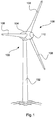
- Figure 1 shows a wind energy installation 100 with a tower 102 and a nacelle 104.
- a rotor 106 with three rotor blades 108 and a spinner 110 is arranged on the nacelle 104.
- the rotor 106 is set in rotation by the wind during operation and thereby drives a generator in the nacelle 104.
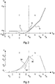
- FIGS 2 and 3 explain possible curves of the blade angle ⁇ and the power P as a function of the wind speed V W. Both figures show the wind speed V W on their abscissa and the abscissas are for both Figures 2 and 3 equal. In this respect, the representation of the power P in Figure 3 the corresponding blade angles ⁇ in Figure 2 be assigned, this assignment is only schematic and not quantitative.
- FIG. 2 a basic profile 2 is now shown with the dashed line for the blade angle ⁇ .
- an improved curve 4 for the blade angle ⁇ is shown with a solid line.
- the improved course 4 corresponds in many sections to the basic course 2 and these two courses are drawn with a small distance only for the sake of better illustration.
- An alternative course 6 is represented by a dotted line and this alternative course 6 otherwise corresponds to the improved course 4 of the blade angle a.
- the wind energy installation starts at a cut-in wind speed V E with an initially fixed partial load angle ⁇ T. As the wind continues to rise, this angle is maintained up to the nominal wind speed V N. When the nominal wind speed V N is reached, the blade is then rotated out of the wind, namely successively as the wind speed continues to rise, and this means that the blade angle ⁇ is gradually increased accordingly.
- the flag position is shown as ⁇ F as the last value for the angle only as an example.
- This basic curve 2 thus shows a constant blade angle ⁇ with the value of the part-load angle ⁇ T in part-load operation T and then an increasing value for full-load operation V.
- a steeper slope of the blade angle is shown for the storm area S, i.e. the blade angle from reaching a Limit wind speed V G is increased even more until it finally reaches the flag position, that is to say the angle ⁇ F , at a cut-off wind speed V A. What exactly happens at the cut-off wind speed V A and whether the plume position is actually reached, how Figure 2 shows, it does not matter here.
- the partial load operation T is divided into three sections I, II and III.
- Section I denotes a lower range of part-load operation
- section II denotes an upper range of part-load operation
- section III finally denotes a third range of part-load operation, which is still above upper range II in relation to the wind speed.
- These sections can also be referred to synonymously as areas.
- full load operation V begins.
- the improved curve 4 corresponds to the basic curve 2.
- the blade angle ⁇ then decreases linearly with increasing wind speed V W. This reduction goes so far that the blade angle ⁇ becomes negative. It then reaches a predetermined minimum blade angle ⁇ min , which here accordingly has a negative value and thus the blade angle ⁇ is then no longer reduced and thus retains this negative value until the end of the upper range II of the partial load operation.
- the blade angle is then increased again, namely in the example linearly with the increase in the wind up to the part-load angle ⁇ T , which is reached when the wind speed V W reaches the nominal wind speed V N.
- a linear increase in the blade angle up to the part-load angle is proposed.
- the blade angle of the improved curve 4 thus again has the partial load angle ⁇ T and the characteristic curve of the basic curve 2 is then reached again at this point.
- the further course of the improved course 4 can then correspond to the further course of the basic course 2, which is correspondingly shown in FIG Figure 2 is shown.
- Figure 3 in any case shows schematically a possible power curve that corresponds to the respective curves of the blade angle Figure 2 assigned.
- a basic curve 32 is shown in dashed lines and an improved curve 34 is entered with a solid line.
- An alternative course 36 is also shown as a dotted characteristic curve in FIG Figure 3 drawn.
- These three courses 32, 34 and 36 thus correspond to courses 2, 4 and 6 of the blade angle according to FIG Figure 2 , with the The difference is that the performance is shown here.
- the base curve 32 is only drawn in as far as it differs from the improved curve 34.
- the power is switched on at the cut-in wind speed V E and has a low value.
- the power then increases continuously, but more and more, until it has reached its nominal value P N at the end of the partial load operation T at the nominal wind speed V N.
- This nominal value is then held for full load operation V and reduced from the limit wind speed V G and reaches a low value, which can also be zero, at the end of the storm region S at the cut-off wind speed V A.
- FIG. 3 now shows that the base curve 32 deviates from the beginning of the upper region II of the partial load operation T, namely has a somewhat lower power.
- this deviation begins at a power value P 1.
- This power value P 1 can thus serve as a predetermined power from which the reduction in the blade angle, which leads to the improved curve 4 in Figure 2 is shown begins.
- the power curve of the improved profile 34 reaches the second predetermined power value P 2 , this can be evaluated or used as information that the end of the upper range II of the partial load operation has been reached and the blade angle should be increased again, as shown in FIG Figure 2 is shown.
- the blade angle is increased again in the third area III of the part-load operation T and reaches the part-load angle ⁇ T at the nominal wind speed.
- the basic curve 32 and the improved curve 34 also coincide again with regard to the generated power P.
- the proposed reduction in the blade angle can sometimes even increase the power output.
- additional advantages can arise here in the course of the service.
- the increase in power is very steep. This means that small changes in wind speed can lead to large changes in performance. In practice, this can mean that small changes in speed can lead to major changes in power. This can raise control problems and the proposed reduction and then again an increase in the blade angle can, depending on the specifically selected values, lead to a not quite as steep increase in the power P in this area.
- the alternative curve 36 for the power P is shown in FIG Figure 3 that in the transition area from part-load operation T to full-load operation V, the power can be slightly reduced compared to the improved curve 34 and also compared to the basic curve 32. For this, however, the load on the blades is reduced in this special area and the increase in power P can also be reduced again in this area, which can be advantageous for the implementation of the regulation.
- Figure 4 now basically shows two profiles 42 and 44 of a rotor blade 40.
- the first profile 42 is in the vicinity of the blade root and the second profile 44 is in the vicinity of the blade tip.
- the profiles are only shown schematically in terms of their size.
- a rest profile 44 ′ is also shown in dotted lines for the second profile 44.
- the second profile 44 and the rest profile 44 ′ are identical, with the difference that the second profile 44 is twisted with respect to the rest profile 44 ′ due to a torsion in the rotor blade 40. This is shown as the torsion angle ⁇ .
- a skeleton line 46, 46 'or 46 * was used as a reference alignment for each of the profiles.
- Figure 4 it can be seen that the rotor blade 40 in its rest position, ie when it is already completed in the factory, has a twist angle ⁇ between the first profile 42 in the root area and the second profile 44 at the blade tip.
- Figure 4 shows an operating point at which the rotor blade 40 is in use and the wind has led to a torsion, accordingly the second profile 44 is rotated by the torsion angle ⁇ with respect to the rest profile 44 ', that is, the second profile 44 in the rest position.
- the blade 40 is thus twisted and leads to this angular deviation according to ⁇ .
- This situation can be related to, for example Figure 2 correspond to the state at the end of the upper range II or at the beginning of the third range III of the partial load operation T.
- the proposed method can thus result in the effects of blade torsion during operation, which are shown in Figure 4 is shown, can be counteracted.
- This counteracting is particularly illustrated by the improved profile 4 of the blade angle ⁇ according to FIG Figure 2 and the basically resulting performance curves are the Figure 3 refer to.
Landscapes
- Engineering & Computer Science (AREA)
- Life Sciences & Earth Sciences (AREA)
- Sustainable Development (AREA)
- Sustainable Energy (AREA)
- Chemical & Material Sciences (AREA)
- Combustion & Propulsion (AREA)
- Mechanical Engineering (AREA)
- General Engineering & Computer Science (AREA)
- Physics & Mathematics (AREA)
- Fluid Mechanics (AREA)
- Wind Motors (AREA)
Claims (11)
- Procédé pour commander une éolienne avec des pales de rotor (40) avec un angle de pale ajustable,
comprenant les étapes- de fonctionnement de l'éolienne dans un mode de fonctionnement en charge partielle (T) pour des vitesses de vent (VW) jusqu'à une vitesse de vent nominale (VN), dans lequel un angle de charge partielle (αT) fixe est prévu dans le mode de fonctionnement en charge partielle (T) pour l'angle de pale (α),- de fonctionnement de l'éolienne dans un mode de fonctionnement en pleine charge (V) pour des vitesses de vent (VW) supérieures à la vitesse de vent nominale (VN), dans lequel dans le mode de fonctionnement en pleine charge (V), l'angle de pale (α) est agrandi au fur et à mesure que la vitesse de vent (VW) augmente et présente des valeurs supérieures à l'angle de charge partielle (αT),comprenant par ailleurs les étapes selon lesquelles- dans le mode de fonctionnement en charge partielle (T), une puissance est réglée en fonction de la vitesse de rotation et l'angle de pale (α) est réduit par rapport à l'angle de charge partielle (αT) à partir d'une vitesse de rotation prédéfinie et/ou à partir d'une puissance prédéfinie, et- que l'angle de pale (α) est ajusté avec une vitesse de rotation qui continue à augmenter ou une puissance qui continue à augmenter en fonction de la vitesse de rotation ou de la puissance de sorte que l'angle de pale (α) est réinitialisé sur l'angle de charge partielle (αT) avant d'atteindre le fonctionnement en pleine charge (V). - Procédé selon la revendication 1, caractérisé en ce que dans le mode de fonctionnement en charge partielle (T), l'angle de pale (a) est ajusté par rapport à l'angle de charge partielle (αT) en fonction d'une torsion d'au moins une des pales de rotor autour d'un axe longitudinal de pale et/ou en fonction d'une contrainte de pale.
- Procédé selon l'une quelconque des revendications précédentes, caractérisé en ce que l'angle de pale (α) est diminué par rapport à l'angle de charge partielle (αT) de manière si importante qu'il adopte une valeur négative.
- Procédé selon l'une quelconque des revendications précédentes, caractérisé en ce qu'au fur et à mesure que la vitesse de vent (VW) augmente, l'angle de pale (α)- présente d'abord l'angle de charge partielle (αT) dans une zone inférieure dans le mode de fonctionnement en charge partielle (T),- est réduit par rapport à l'angle de charge partielle (αT) dans une zone supérieure dans le mode de fonctionnement en charge partielle (T) et- est augmenté par rapport à l'angle de charge partielle (αT) dans le mode de fonctionnement en pleine charge (V).
- Procédé selon la revendication 4, caractérisé en ce qu'est prévue, dans le mode de fonctionnement en charge partielle (T), dans le prolongement de la zone supérieure (II), une troisième zone (III), dans le prolongement de la laquelle se trouve le mode de fonctionnement en pleine charge et dans laquelle l'angle de pale (α) est augmenté au moins jusqu'à l'angle de charge partielle (αT).
- Procédé selon l'une quelconque des revendications précédentes, caractérisé en ce que l'angle de pale (α) est diminué dans une ou la zone supérieure (II) dans le mode de fonctionnement en charge partielle (T) en fonction de la puissance et/ou en fonction de la vitesse de rotation avec un gradient prédéfini et/ou en fonction d'un rapport prédéfini de la puissance ou de la vitesse de rotation.
- Procédé selon l'une quelconque des revendications précédentes, caractérisé en ce que l'angle de pale (α) est ajusté, dans le mode de fonctionnement en charge partielle (T), par rapport à l'angle de charge partielle (αT) en fonction d'au moins une propriété de l'air, en particulier en fonction de la densité de l'air et/ou en fonction d'une caractéristique du vent, en particulier en fonction de l'intensité des rafales de vent.
- Procédé selon l'une quelconque des revendications précédentes, caractérisé en ce que sont prévus des moyens de mesure pour détecter une torsion d'au moins une des pales de rotor autour de leur axe longitudinal et la torsion ainsi détectée est utilisée en tant que critère pour ajuster l'angle de pale (α), en particulier que plus la torsion détectée est grande, plus l'ajustement de l'angle de pale (α) est important.
- Procédé selon l'une quelconque des revendications précédentes, caractérisé en ce que l'éolienne présente plusieurs pales de rotor, en particulier trois, et chaque pale de rotor est ajustée de manière individuelle et/ou selon un cycle de rotation, en particulier de telle sorte que l'angle de pale (α) individuel ou sa valeur théorique se compose d'un angle de base identique pour toutes les pales de rotor et d'un angle supplémentaire prévu de manière individuelle pour chaque pale de rotor.
- Procédé selon l'une quelconque des revendications précédentes, caractérisé en ce qu'est prévu un angle de pale minimal (αmin), qui est inférieur à l'angle de charge partielle (αT) et l'angle de pale (α) peut être ajusté, éventuellement individuellement pour chaque pale de rotor, jusqu'audit angle de pale minimal (αmin).
- Eolienne avec un rotor, qui présente des pales de rotor, dont l'angle de pale peut être ajusté, ainsi qu'avec des moyens qui sont mis au point pour- faire fonctionner l'éolienne dans un mode de fonctionnement en charge partielle (T) pour des vitesses de vent (VW) jusqu'à une vitesse de vent nominale (VN), dans lequel dans le mode de fonctionnement en charge partielle (T), un angle de charge partielle (αT) fixe est prévu pour l'angle de pale (α),- faire fonctionner l'éolienne dans un mode de fonctionnement en pleine charge (V) pour des vitesses de vent (VW) supérieures à la vitesse de vent nominale (VN), dans lequel dans le mode de fonctionnement en pleine charge (V), l'angle de pale (α) est agrandi au fur et à mesure que la vitesse de vent (VW) augmente et présente des valeurs supérieures à l'angle de charge partielle (αT),ainsi qu'avec des moyens qui sont mis au point pour- régler, dans le mode de fonctionnement en charge partielle (T), une puissance en fonction de la vitesse de rotation et pour réduire, à partir d'une vitesse de rotation prédéfinie et/ou à partir d'une puissance prédéfinie, l'angle de pale (α) par rapport à l'angle de charge partielle (αT), et- ajuster l'angle de pale (α) avec une vitesse de rotation qui continue à augmenter ou une puissance qui continue à augmenter en fonction de la vitesse de rotation ou de la puissance pour réinitialiser l'angle de pale (α) sur l'angle de charge partielle (αT) avant d'atteindre le mode de fonctionnement en pleine charge (V).
Applications Claiming Priority (2)
| Application Number | Priority Date | Filing Date | Title |
|---|---|---|---|
| DE102015119986.6A DE102015119986A1 (de) | 2015-11-18 | 2015-11-18 | Steuerung einer Windenergieanlage mit verstellbaren Rotorblättern |
| PCT/EP2016/077928 WO2017085156A1 (fr) | 2015-11-18 | 2016-11-17 | Commande d'une éolienne à pales de rotor réglables |
Publications (2)
| Publication Number | Publication Date |
|---|---|
| EP3377759A1 EP3377759A1 (fr) | 2018-09-26 |
| EP3377759B1 true EP3377759B1 (fr) | 2021-05-12 |
Family
ID=57326411
Family Applications (1)
| Application Number | Title | Priority Date | Filing Date |
|---|---|---|---|
| EP16797557.2A Active EP3377759B1 (fr) | 2015-11-18 | 2016-11-17 | Commande d'une éolienne à pales de rotor réglables |
Country Status (9)
| Country | Link |
|---|---|
| US (1) | US10865771B2 (fr) |
| EP (1) | EP3377759B1 (fr) |
| JP (1) | JP2018535354A (fr) |
| CN (1) | CN108350861B (fr) |
| BR (1) | BR112018010011A2 (fr) |
| CA (1) | CA3003381C (fr) |
| DE (1) | DE102015119986A1 (fr) |
| DK (1) | DK3377759T3 (fr) |
| WO (1) | WO2017085156A1 (fr) |
Families Citing this family (10)
| Publication number | Priority date | Publication date | Assignee | Title |
|---|---|---|---|---|
| US11286911B2 (en) | 2017-05-26 | 2022-03-29 | Vestas Wind Systems A/S | Relating to wind turbine rotor angle sensing systems |
| DE102017011512A1 (de) | 2017-12-13 | 2019-06-13 | Senvion Gmbh | Verfahren und System zum Betreiben einer Windenergieanlage |
| DE102018100127A1 (de) * | 2018-01-04 | 2019-07-04 | Wobben Properties Gmbh | Betreiben einer Windenergieanlage bei Sturm |
| JP2019178615A (ja) * | 2018-03-30 | 2019-10-17 | 株式会社日立製作所 | 風力発電システム |
| CN109139372B (zh) * | 2018-08-06 | 2020-01-10 | 大连理工大学 | 一种基于独立变桨的风电机组控制和制动方法 |
| DE102018124084A1 (de) | 2018-09-28 | 2020-04-02 | Wobben Properties Gmbh | Verfahren zum Betreiben einer Windenergieanlage, Windenergieanlage und Windpark |
| JP7209542B2 (ja) * | 2019-01-08 | 2023-01-20 | 株式会社日立製作所 | 風力発電装置とその運転方法 |
| CN114303012B (zh) | 2019-06-27 | 2025-02-18 | 维斯塔斯风力系统集团公司 | 低于额定风速时控制风力涡轮机的功率输出 |
| WO2022118327A1 (fr) * | 2020-12-01 | 2022-06-09 | Sunit Tyagi | Appareil et procédé pour éoliennes fonctionnant lors de vents forts et d'ouragans |
| EP4234920B1 (fr) * | 2022-02-23 | 2025-01-01 | Wobben Properties GmbH | Réglage individuel des pales dans une éolienne |
Family Cites Families (16)
| Publication number | Priority date | Publication date | Assignee | Title |
|---|---|---|---|---|
| DE19532409B4 (de) | 1995-09-01 | 2005-05-12 | Wobben, Aloys, Dipl.-Ing. | Verfahren zum Betreiben einer Windenergieanlage und eine zugehörige Windenergieanlage |
| ATE275240T1 (de) * | 1999-11-03 | 2004-09-15 | Vestas Wind Sys As | Methode zur regelung einer windkraftanlage sowie entsprechende windkraftanlage |
| JP2004308498A (ja) * | 2003-04-03 | 2004-11-04 | Mie Tlo Co Ltd | 風力発電装置 |
| GB2479415A (en) * | 2010-04-09 | 2011-10-12 | Vestas Wind Sys As | Wind Turbine Independent Blade Control Outside The Rated Output |
| GB2479923A (en) * | 2010-04-29 | 2011-11-02 | Vestas Wind Sys As | A method and system for detecting angular deflection in a wind turbine blade, or component, or between wind turbine components |
| GB2482009B (en) * | 2010-07-14 | 2014-07-23 | Vestas Wind Sys As | Ice detection and system for wind turbine blades |
| CN103384764B (zh) * | 2010-12-21 | 2016-03-23 | 维斯塔斯风力系统集团公司 | 风轮机的控制方法 |
| DE102011006670A1 (de) * | 2011-04-01 | 2012-10-04 | Aloys Wobben | Windenergieanlage und Verfahren zum Betreiben einer Windenergieanlage |
| EP2530302B1 (fr) | 2011-06-03 | 2014-04-30 | Wilic S.Àr.L | Éolienne et procédé de contrôle associé |
| DK201270417A (en) * | 2012-07-09 | 2014-01-10 | Envision Energy Denmark Aps | Method and System to Actively Pitch to Reduce Extreme Loads on Wind Turbine |
| EP2848805B1 (fr) * | 2013-09-17 | 2019-01-02 | Alstom Renovables España, S.L. | Procédé de fonctionnement d'une éolienne |
| WO2016023554A1 (fr) * | 2014-08-15 | 2016-02-18 | Vestas Wind Systems A/S | Augmentation de la puissance nominale de turbine à l'aide d'une prédiction de turbulence |
| US20160178084A1 (en) | 2014-12-18 | 2016-06-23 | Black & Decker Inc. | Pressure-Setting Regulator |
| EP3034867B1 (fr) * | 2014-12-19 | 2018-02-14 | ALSTOM Renewable Technologies | Corrosion de contact et procédés de fonctionnement d'une turbine éolienne |
| WO2016101961A1 (fr) * | 2014-12-23 | 2016-06-30 | Vestas Wind Systems A/S | Procédé et système de détermination de la torsion dynamique d'une pale d'éolienne |
| EP3250820B1 (fr) * | 2015-01-29 | 2018-10-17 | Vestas Wind Systems A/S | Contrôleurs de charge partielle et de pleine charge d'éolienne |
-
2015
- 2015-11-18 DE DE102015119986.6A patent/DE102015119986A1/de not_active Withdrawn
-
2016
- 2016-11-17 DK DK16797557.2T patent/DK3377759T3/da active
- 2016-11-17 BR BR112018010011-0A patent/BR112018010011A2/pt not_active IP Right Cessation
- 2016-11-17 CA CA3003381A patent/CA3003381C/fr not_active Expired - Fee Related
- 2016-11-17 WO PCT/EP2016/077928 patent/WO2017085156A1/fr not_active Ceased
- 2016-11-17 EP EP16797557.2A patent/EP3377759B1/fr active Active
- 2016-11-17 JP JP2018526176A patent/JP2018535354A/ja not_active Ceased
- 2016-11-17 CN CN201680067032.0A patent/CN108350861B/zh active Active
- 2016-11-17 US US15/775,727 patent/US10865771B2/en active Active
Non-Patent Citations (1)
| Title |
|---|
| None * |
Also Published As
| Publication number | Publication date |
|---|---|
| EP3377759A1 (fr) | 2018-09-26 |
| US20180328339A1 (en) | 2018-11-15 |
| CA3003381C (fr) | 2020-06-02 |
| JP2018535354A (ja) | 2018-11-29 |
| US10865771B2 (en) | 2020-12-15 |
| CA3003381A1 (fr) | 2017-05-26 |
| DE102015119986A1 (de) | 2017-05-18 |
| DK3377759T3 (da) | 2021-07-26 |
| WO2017085156A1 (fr) | 2017-05-26 |
| CN108350861B (zh) | 2021-01-26 |
| BR112018010011A2 (pt) | 2018-11-21 |
| CN108350861A (zh) | 2018-07-31 |
Similar Documents
| Publication | Publication Date | Title |
|---|---|---|
| DE102004054608B4 (de) | Verfahren zur Regelung einer Windenergieanlage und Windenergieanlage mit einem Rotor | |
| EP3377759A1 (fr) | Commande d'une éolienne à pales de rotor réglables | |
| EP3735532B1 (fr) | Fonctionnement d'une éolienne en cas de tempête | |
| EP2906824B1 (fr) | Procédé pour faire fonctionner une éolienne | |
| DE10319246A1 (de) | Rotorblatt einer Windenergieanlage | |
| EP3803109B1 (fr) | Procédé pour faire fonctionner une éolienne | |
| EP3857051B1 (fr) | Procédé pour faire fonctionner une éolienne, éolienne et parc éolien | |
| DE102010027003B4 (de) | Rotor für eine Windenergieanlage und Verfahren zur Regelung des Rotors | |
| EP3489507B1 (fr) | Procédé et dispositif destinés au fonctionnement d'une éolienne | |
| EP2923079A1 (fr) | Procédé pour faire fonctionner une éolienne et éolienne | |
| WO2017178429A1 (fr) | Procédé pour faire fonctionner une éolienne | |
| WO2018109100A1 (fr) | Procédé pour faire fonctionner un aérogénérateur ainsi que dispositif pour commander et/ou réguler un aérogénérateur et aérogénérateur correspondant comprenant un rotor et un générateur entraîné par le biais du rotor pour générer une puissance électrique | |
| EP3884153B1 (fr) | Structure de régulation et procédé de régulation pour une éolienne | |
| EP3390813A1 (fr) | Procédé de commande d'une éolienne | |
| EP3555462B1 (fr) | Procédé permettant de commander une éolienne | |
| EP3165765B1 (fr) | Procédé et système de commande d'un angle d'attaque d'une pale de rotor et éolienne et procédé de fonctionnement d'une éolienne | |
| EP3842633A1 (fr) | Procédé de fonctionnement d'une éolienne, éolienne et parc éolien | |
| EP3464884B1 (fr) | Pale de rotor d'une éolienne | |
| DE102014216685A1 (de) | Verwindbares Rotorblatt | |
| EP4148270B1 (fr) | Procédé d'ajustement d'une courbe caractéristique de fonctionnement d'une éolienne | |
| EP3887676B1 (fr) | Procédé permettant de faire fonctionner une éolienne | |
| DE102009004070A1 (de) | Windenergieanlage | |
| EP3887674A1 (fr) | Procédé et système permettant de faire fonctionner une éolienne |
Legal Events
| Date | Code | Title | Description |
|---|---|---|---|
| STAA | Information on the status of an ep patent application or granted ep patent |
Free format text: STATUS: UNKNOWN |
|
| STAA | Information on the status of an ep patent application or granted ep patent |
Free format text: STATUS: THE INTERNATIONAL PUBLICATION HAS BEEN MADE |
|
| PUAI | Public reference made under article 153(3) epc to a published international application that has entered the european phase |
Free format text: ORIGINAL CODE: 0009012 |
|
| STAA | Information on the status of an ep patent application or granted ep patent |
Free format text: STATUS: REQUEST FOR EXAMINATION WAS MADE |
|
| 17P | Request for examination filed |
Effective date: 20180618 |
|
| AK | Designated contracting states |
Kind code of ref document: A1 Designated state(s): AL AT BE BG CH CY CZ DE DK EE ES FI FR GB GR HR HU IE IS IT LI LT LU LV MC MK MT NL NO PL PT RO RS SE SI SK SM TR |
|
| AX | Request for extension of the european patent |
Extension state: BA ME |
|
| DAV | Request for validation of the european patent (deleted) | ||
| DAX | Request for extension of the european patent (deleted) | ||
| STAA | Information on the status of an ep patent application or granted ep patent |
Free format text: STATUS: EXAMINATION IS IN PROGRESS |
|
| 17Q | First examination report despatched |
Effective date: 20200908 |
|
| GRAP | Despatch of communication of intention to grant a patent |
Free format text: ORIGINAL CODE: EPIDOSNIGR1 |
|
| STAA | Information on the status of an ep patent application or granted ep patent |
Free format text: STATUS: GRANT OF PATENT IS INTENDED |
|
| INTG | Intention to grant announced |
Effective date: 20201218 |
|
| GRAS | Grant fee paid |
Free format text: ORIGINAL CODE: EPIDOSNIGR3 |
|
| GRAA | (expected) grant |
Free format text: ORIGINAL CODE: 0009210 |
|
| STAA | Information on the status of an ep patent application or granted ep patent |
Free format text: STATUS: THE PATENT HAS BEEN GRANTED |
|
| AK | Designated contracting states |
Kind code of ref document: B1 Designated state(s): AL AT BE BG CH CY CZ DE DK EE ES FI FR GB GR HR HU IE IS IT LI LT LU LV MC MK MT NL NO PL PT RO RS SE SI SK SM TR |
|
| REG | Reference to a national code |
Ref country code: GB Ref legal event code: FG4D Free format text: NOT ENGLISH |
|
| RIN1 | Information on inventor provided before grant (corrected) |
Inventor name: ALTMIKUS, ANDREE Inventor name: DE BOER, WOLFGANG Inventor name: MESSING, RALF |
|
| REG | Reference to a national code |
Ref country code: CH Ref legal event code: EP |
|
| REG | Reference to a national code |
Ref country code: DE Ref legal event code: R096 Ref document number: 502016013039 Country of ref document: DE |
|
| REG | Reference to a national code |
Ref country code: IE Ref legal event code: FG4D Free format text: LANGUAGE OF EP DOCUMENT: GERMAN |
|
| REG | Reference to a national code |
Ref country code: AT Ref legal event code: REF Ref document number: 1392342 Country of ref document: AT Kind code of ref document: T Effective date: 20210615 |
|
| REG | Reference to a national code |
Ref country code: NL Ref legal event code: FP |
|
| REG | Reference to a national code |
Ref country code: DK Ref legal event code: T3 Effective date: 20210721 |
|
| REG | Reference to a national code |
Ref country code: LT Ref legal event code: MG9D |
|
| PG25 | Lapsed in a contracting state [announced via postgrant information from national office to epo] |
Ref country code: LT Free format text: LAPSE BECAUSE OF FAILURE TO SUBMIT A TRANSLATION OF THE DESCRIPTION OR TO PAY THE FEE WITHIN THE PRESCRIBED TIME-LIMIT Effective date: 20210512 Ref country code: FI Free format text: LAPSE BECAUSE OF FAILURE TO SUBMIT A TRANSLATION OF THE DESCRIPTION OR TO PAY THE FEE WITHIN THE PRESCRIBED TIME-LIMIT Effective date: 20210512 Ref country code: BG Free format text: LAPSE BECAUSE OF FAILURE TO SUBMIT A TRANSLATION OF THE DESCRIPTION OR TO PAY THE FEE WITHIN THE PRESCRIBED TIME-LIMIT Effective date: 20210812 Ref country code: HR Free format text: LAPSE BECAUSE OF FAILURE TO SUBMIT A TRANSLATION OF THE DESCRIPTION OR TO PAY THE FEE WITHIN THE PRESCRIBED TIME-LIMIT Effective date: 20210512 |
|
| PG25 | Lapsed in a contracting state [announced via postgrant information from national office to epo] |
Ref country code: LV Free format text: LAPSE BECAUSE OF FAILURE TO SUBMIT A TRANSLATION OF THE DESCRIPTION OR TO PAY THE FEE WITHIN THE PRESCRIBED TIME-LIMIT Effective date: 20210512 Ref country code: GR Free format text: LAPSE BECAUSE OF FAILURE TO SUBMIT A TRANSLATION OF THE DESCRIPTION OR TO PAY THE FEE WITHIN THE PRESCRIBED TIME-LIMIT Effective date: 20210813 Ref country code: IS Free format text: LAPSE BECAUSE OF FAILURE TO SUBMIT A TRANSLATION OF THE DESCRIPTION OR TO PAY THE FEE WITHIN THE PRESCRIBED TIME-LIMIT Effective date: 20210912 Ref country code: NO Free format text: LAPSE BECAUSE OF FAILURE TO SUBMIT A TRANSLATION OF THE DESCRIPTION OR TO PAY THE FEE WITHIN THE PRESCRIBED TIME-LIMIT Effective date: 20210812 Ref country code: PL Free format text: LAPSE BECAUSE OF FAILURE TO SUBMIT A TRANSLATION OF THE DESCRIPTION OR TO PAY THE FEE WITHIN THE PRESCRIBED TIME-LIMIT Effective date: 20210512 Ref country code: PT Free format text: LAPSE BECAUSE OF FAILURE TO SUBMIT A TRANSLATION OF THE DESCRIPTION OR TO PAY THE FEE WITHIN THE PRESCRIBED TIME-LIMIT Effective date: 20210913 Ref country code: SE Free format text: LAPSE BECAUSE OF FAILURE TO SUBMIT A TRANSLATION OF THE DESCRIPTION OR TO PAY THE FEE WITHIN THE PRESCRIBED TIME-LIMIT Effective date: 20210512 Ref country code: RS Free format text: LAPSE BECAUSE OF FAILURE TO SUBMIT A TRANSLATION OF THE DESCRIPTION OR TO PAY THE FEE WITHIN THE PRESCRIBED TIME-LIMIT Effective date: 20210512 |
|
| PG25 | Lapsed in a contracting state [announced via postgrant information from national office to epo] |
Ref country code: ES Free format text: LAPSE BECAUSE OF FAILURE TO SUBMIT A TRANSLATION OF THE DESCRIPTION OR TO PAY THE FEE WITHIN THE PRESCRIBED TIME-LIMIT Effective date: 20210512 Ref country code: RO Free format text: LAPSE BECAUSE OF FAILURE TO SUBMIT A TRANSLATION OF THE DESCRIPTION OR TO PAY THE FEE WITHIN THE PRESCRIBED TIME-LIMIT Effective date: 20210512 Ref country code: SM Free format text: LAPSE BECAUSE OF FAILURE TO SUBMIT A TRANSLATION OF THE DESCRIPTION OR TO PAY THE FEE WITHIN THE PRESCRIBED TIME-LIMIT Effective date: 20210512 Ref country code: SK Free format text: LAPSE BECAUSE OF FAILURE TO SUBMIT A TRANSLATION OF THE DESCRIPTION OR TO PAY THE FEE WITHIN THE PRESCRIBED TIME-LIMIT Effective date: 20210512 Ref country code: CZ Free format text: LAPSE BECAUSE OF FAILURE TO SUBMIT A TRANSLATION OF THE DESCRIPTION OR TO PAY THE FEE WITHIN THE PRESCRIBED TIME-LIMIT Effective date: 20210512 Ref country code: EE Free format text: LAPSE BECAUSE OF FAILURE TO SUBMIT A TRANSLATION OF THE DESCRIPTION OR TO PAY THE FEE WITHIN THE PRESCRIBED TIME-LIMIT Effective date: 20210512 |
|
| REG | Reference to a national code |
Ref country code: DE Ref legal event code: R097 Ref document number: 502016013039 Country of ref document: DE |
|
| PLBE | No opposition filed within time limit |
Free format text: ORIGINAL CODE: 0009261 |
|
| STAA | Information on the status of an ep patent application or granted ep patent |
Free format text: STATUS: NO OPPOSITION FILED WITHIN TIME LIMIT |
|
| 26N | No opposition filed |
Effective date: 20220215 |
|
| PG25 | Lapsed in a contracting state [announced via postgrant information from national office to epo] |
Ref country code: IS Free format text: LAPSE BECAUSE OF FAILURE TO SUBMIT A TRANSLATION OF THE DESCRIPTION OR TO PAY THE FEE WITHIN THE PRESCRIBED TIME-LIMIT Effective date: 20210912 Ref country code: AL Free format text: LAPSE BECAUSE OF FAILURE TO SUBMIT A TRANSLATION OF THE DESCRIPTION OR TO PAY THE FEE WITHIN THE PRESCRIBED TIME-LIMIT Effective date: 20210512 |
|
| PG25 | Lapsed in a contracting state [announced via postgrant information from national office to epo] |
Ref country code: MC Free format text: LAPSE BECAUSE OF FAILURE TO SUBMIT A TRANSLATION OF THE DESCRIPTION OR TO PAY THE FEE WITHIN THE PRESCRIBED TIME-LIMIT Effective date: 20210512 |
|
| REG | Reference to a national code |
Ref country code: CH Ref legal event code: PL |
|
| PG25 | Lapsed in a contracting state [announced via postgrant information from national office to epo] |
Ref country code: LU Free format text: LAPSE BECAUSE OF NON-PAYMENT OF DUE FEES Effective date: 20211117 Ref country code: IT Free format text: LAPSE BECAUSE OF FAILURE TO SUBMIT A TRANSLATION OF THE DESCRIPTION OR TO PAY THE FEE WITHIN THE PRESCRIBED TIME-LIMIT Effective date: 20210512 Ref country code: BE Free format text: LAPSE BECAUSE OF NON-PAYMENT OF DUE FEES Effective date: 20211130 |
|
| REG | Reference to a national code |
Ref country code: BE Ref legal event code: MM Effective date: 20211130 |
|
| PG25 | Lapsed in a contracting state [announced via postgrant information from national office to epo] |
Ref country code: LI Free format text: LAPSE BECAUSE OF NON-PAYMENT OF DUE FEES Effective date: 20211130 Ref country code: CH Free format text: LAPSE BECAUSE OF NON-PAYMENT OF DUE FEES Effective date: 20211130 |
|
| PG25 | Lapsed in a contracting state [announced via postgrant information from national office to epo] |
Ref country code: IE Free format text: LAPSE BECAUSE OF NON-PAYMENT OF DUE FEES Effective date: 20211117 |
|
| REG | Reference to a national code |
Ref country code: AT Ref legal event code: MM01 Ref document number: 1392342 Country of ref document: AT Kind code of ref document: T Effective date: 20211117 |
|
| PG25 | Lapsed in a contracting state [announced via postgrant information from national office to epo] |
Ref country code: AT Free format text: LAPSE BECAUSE OF NON-PAYMENT OF DUE FEES Effective date: 20211117 |
|
| PG25 | Lapsed in a contracting state [announced via postgrant information from national office to epo] |
Ref country code: HU Free format text: LAPSE BECAUSE OF FAILURE TO SUBMIT A TRANSLATION OF THE DESCRIPTION OR TO PAY THE FEE WITHIN THE PRESCRIBED TIME-LIMIT; INVALID AB INITIO Effective date: 20161117 |
|
| PG25 | Lapsed in a contracting state [announced via postgrant information from national office to epo] |
Ref country code: CY Free format text: LAPSE BECAUSE OF FAILURE TO SUBMIT A TRANSLATION OF THE DESCRIPTION OR TO PAY THE FEE WITHIN THE PRESCRIBED TIME-LIMIT Effective date: 20210512 |
|
| PG25 | Lapsed in a contracting state [announced via postgrant information from national office to epo] |
Ref country code: MK Free format text: LAPSE BECAUSE OF FAILURE TO SUBMIT A TRANSLATION OF THE DESCRIPTION OR TO PAY THE FEE WITHIN THE PRESCRIBED TIME-LIMIT Effective date: 20210512 |
|
| PG25 | Lapsed in a contracting state [announced via postgrant information from national office to epo] |
Ref country code: TR Free format text: LAPSE BECAUSE OF FAILURE TO SUBMIT A TRANSLATION OF THE DESCRIPTION OR TO PAY THE FEE WITHIN THE PRESCRIBED TIME-LIMIT Effective date: 20210512 |
|
| PG25 | Lapsed in a contracting state [announced via postgrant information from national office to epo] |
Ref country code: MT Free format text: LAPSE BECAUSE OF FAILURE TO SUBMIT A TRANSLATION OF THE DESCRIPTION OR TO PAY THE FEE WITHIN THE PRESCRIBED TIME-LIMIT Effective date: 20210512 |
|
| PGFP | Annual fee paid to national office [announced via postgrant information from national office to epo] |
Ref country code: NL Payment date: 20251119 Year of fee payment: 10 |
|
| PGFP | Annual fee paid to national office [announced via postgrant information from national office to epo] |
Ref country code: DE Payment date: 20251201 Year of fee payment: 10 |
|
| PGFP | Annual fee paid to national office [announced via postgrant information from national office to epo] |
Ref country code: GB Payment date: 20251120 Year of fee payment: 10 |
|
| PGFP | Annual fee paid to national office [announced via postgrant information from national office to epo] |
Ref country code: DK Payment date: 20251119 Year of fee payment: 10 |
|
| PGFP | Annual fee paid to national office [announced via postgrant information from national office to epo] |
Ref country code: FR Payment date: 20251120 Year of fee payment: 10 |