EP3377801B1 - Ensemble comportant au moins une source de tir et au moins un dispositif de détection - Google Patents
Ensemble comportant au moins une source de tir et au moins un dispositif de détection Download PDFInfo
- Publication number
- EP3377801B1 EP3377801B1 EP16794202.8A EP16794202A EP3377801B1 EP 3377801 B1 EP3377801 B1 EP 3377801B1 EP 16794202 A EP16794202 A EP 16794202A EP 3377801 B1 EP3377801 B1 EP 3377801B1
- Authority
- EP
- European Patent Office
- Prior art keywords
- conductive layers
- electrically conductive
- electrically
- measuring channels
- layers
- Prior art date
- Legal status (The legal status is an assumption and is not a legal conclusion. Google has not performed a legal analysis and makes no representation as to the accuracy of the status listed.)
- Active
Links
Images
Classifications
-
- F—MECHANICAL ENGINEERING; LIGHTING; HEATING; WEAPONS; BLASTING
- F16—ENGINEERING ELEMENTS AND UNITS; GENERAL MEASURES FOR PRODUCING AND MAINTAINING EFFECTIVE FUNCTIONING OF MACHINES OR INSTALLATIONS; THERMAL INSULATION IN GENERAL
- F16P—SAFETY DEVICES IN GENERAL; SAFETY DEVICES FOR PRESSES
- F16P1/00—Safety devices independent of the control and operation of any machine
- F16P1/06—Safety devices independent of the control and operation of any machine specially designed for welding
-
- B—PERFORMING OPERATIONS; TRANSPORTING
- B23—MACHINE TOOLS; METAL-WORKING NOT OTHERWISE PROVIDED FOR
- B23K—SOLDERING OR UNSOLDERING; WELDING; CLADDING OR PLATING BY SOLDERING OR WELDING; CUTTING BY APPLYING HEAT LOCALLY, e.g. FLAME CUTTING; WORKING BY LASER BEAM
- B23K26/00—Working by laser beam, e.g. welding, cutting or boring
- B23K26/08—Devices involving relative movement between laser beam and workpiece
- B23K26/0869—Devices involving movement of the laser head in at least one axial direction
- B23K26/0876—Devices involving movement of the laser head in at least one axial direction in at least two axial directions
- B23K26/0884—Devices involving movement of the laser head in at least one axial direction in at least two axial directions in at least three axial directions, e.g. manipulators, robots
-
- B—PERFORMING OPERATIONS; TRANSPORTING
- B23—MACHINE TOOLS; METAL-WORKING NOT OTHERWISE PROVIDED FOR
- B23K—SOLDERING OR UNSOLDERING; WELDING; CLADDING OR PLATING BY SOLDERING OR WELDING; CUTTING BY APPLYING HEAT LOCALLY, e.g. FLAME CUTTING; WORKING BY LASER BEAM
- B23K26/00—Working by laser beam, e.g. welding, cutting or boring
- B23K26/20—Bonding
- B23K26/21—Bonding by welding
-
- B—PERFORMING OPERATIONS; TRANSPORTING
- B23—MACHINE TOOLS; METAL-WORKING NOT OTHERWISE PROVIDED FOR
- B23K—SOLDERING OR UNSOLDERING; WELDING; CLADDING OR PLATING BY SOLDERING OR WELDING; CUTTING BY APPLYING HEAT LOCALLY, e.g. FLAME CUTTING; WORKING BY LASER BEAM
- B23K26/00—Working by laser beam, e.g. welding, cutting or boring
- B23K26/70—Auxiliary operations or equipment
- B23K26/702—Auxiliary equipment
- B23K26/706—Protective screens
-
- B—PERFORMING OPERATIONS; TRANSPORTING
- B23—MACHINE TOOLS; METAL-WORKING NOT OTHERWISE PROVIDED FOR
- B23K—SOLDERING OR UNSOLDERING; WELDING; CLADDING OR PLATING BY SOLDERING OR WELDING; CUTTING BY APPLYING HEAT LOCALLY, e.g. FLAME CUTTING; WORKING BY LASER BEAM
- B23K37/00—Auxiliary devices or processes, not specially adapted for a procedure covered by only one of the other main groups of this subclass
- B23K37/006—Safety devices for welding or cutting
Definitions
- the present invention relates to an arrangement according to the preamble of patent claim 1.
- the detector devices of such arrangements are e.g. used as laser protection walls. They are used to monitor shot sources in the form of laser devices and to detect when a laser beam leaves its prescribed work area due to operating or programming errors or the like. They thus serve as a safety device to prevent dangers to people, machines and the environment.
- Corresponding detector devices or laser protection walls are used in connection with welding robots or the like.
- the laser protective walls or detector devices can e.g. are used to form a laser protection cabin, which encases a welding robot or other laser devices and his or her work area.
- the DE 10 2012 106 277 A1 discloses a laser protection device with a multilayer structure in which a layer of dielectric material is arranged between two electrically conductive layers. The electrical conductivity between the two electrically conductive layers is measured.
- the US 5,151,095 A discloses a structure similar to this.
- the EP 2 592 326 B1 shows a non-generic structure, in which conductor tracks are arranged only on the side of the electrically separating layer facing away from the shot source or the laser. According to this document, the electrically separating layer should be charred in the event of laser penetration so that it then forms an electrically conductive connection between the conductor tracks.
- the object of the invention is to design an alternative arrangement of the type mentioned at the outset in such a way that it can be produced very cost-effectively on the one hand and is also very reliable on the other hand.
- a basic idea of the invention is that an electrical connection or short-circuit between the two electrically conductive layers or a change in the electrical properties of the electrically conductive layers monitored by means of the measuring channels occurs when a bullet is shot into or through the fabric .
- a hole is formed in the electrically separating layer when the bullet is fired or shot through, as a result of which the respective electrical parameter changes in at least one, usually even in both measuring channels, which is determined and monitored accordingly by the evaluation device or measured in other words becomes.
- a first advantage of this structure is that very inexpensive materials can be used to form the electrically separating and also the electrically conductive layers, and the electrical structure as a whole can also be very simple.
- the electrically separating layers can be made thin and from inexpensive material, since they are in or when they are shot through Favorably disappear completely in the area, so that there the materials of the conductive layers preferably come into direct contact with one another or are directly connected to one another.
- Another advantage of the embodiment of the detector device according to the invention is that the two measuring channels can be used to permanently monitor that there is no fault in the overall system. As soon as a fault occurs, for example due to a loose contact or the corresponding connections being torn off in one of the measuring channels, there is also a change in at least one of the electrical parameters monitored or measured in the measuring channels, which in turn can be determined immediately with the evaluation device.
- the monitoring of the at least two measuring channels advantageously takes place permanently.
- the evaluation device can emit a warning and / or shutdown signal.
- the evaluation device has at least one signal output for emitting a warning and / or shutdown signal.
- Arrangements according to the invention can be used, for example, to monitor that a laser beam generated by a shot source in the form of a welding robot or another laser device does not leave its predetermined area. If he does so, there is a bullet or bullet in the fabric of the Detector device, with which the evaluation device then detects a change in the first electrical parameter in one of the measurement channels and / or a change in the second electrical parameter in another of the measurement channels and can emit corresponding warning and / or shutdown signals.
- these switch-off signals can be used to switch off the shot source, for example the welding robot or the laser device. It is also possible to trigger various optical and / or acoustic or other warning messages.
- detector devices according to the invention can not only be used to monitor shot sources in the form of lasers. Rather, it is possible to use them where there are fears of flying metal or other particles from other shot sources.
- a corresponding bullet and / or bullet in the flat structure of the detector device which can be detected by the detector device according to the invention, can also be generated by a projectile of a firing source in the form of a firearm or a fragment or the like emitted by another firing source and flying around.
- Detector devices according to the invention can therefore also delimit areas with their flat structures in which it is to be ensured or monitored that projectiles, fragments and the like do not leave these areas.
- the flat structures of the detector device can be designed as wall elements. These are then preferably self-supporting or rigid in themselves. However, it is equally possible to design sheet-like structures according to the invention as flexible curtains, which can then even be rolled up or the like if necessary.
- the flat structures of arrangements according to the invention can be designed as individual walls or curtains or as wall or curtain arrangements. But they can also be used as housings, cabins and the like, e.g. Laser cabins should be designed.
- the electrically conductive layers preferably have a specific ohmic resistance of less than or equal to 5 ⁇ mm 2 / m (ohm times square millimeter by meter), preferably less than or equal to 1 ⁇ mm 2 / m.
- the specific ohmic resistance of the electrically conductive layers in a range from 0.001 ⁇ mm 2 / m to 1 ⁇ mm 2 / m.
- aluminum, steel, copper or brass in pure form or as alloys can be used as material for forming these electrically conductive layers.
- the electrically conductive layers can be designed as plates but also as flexible mats, foils, fabrics or the like.
- the thickness of the electrically conductive layers is advantageously between 0.1 mm (millimeters) and 10 mm, preferably between 1 mm and 3 mm.
- the electrically separating layers have a higher specific ohmic resistance than the electrically conductive layers.
- the specific ohmic resistance of the electrically separating layers is advantageously in a range greater than or equal to 10 ⁇ mm 2 / m.
- the electrically separating layers are therefore preferably electrically insulating layers. Conveniently, they have a thickness between 0.01 mm and 2 mm. They can be designed as a coating, varnish, film, anodization, knitwear, mat or as a plate.
- the electrically conductive and / or also the electrically separating layers are preferably in each case self-contained surfaces which, in other words, are formed over the entire surface. This means that the surfaces or layers have no openings, holes or passages, e.g. is not a mesh, knitted fabric or the like.
- the detector device additionally has a third measuring channel, which monitors a third electrical parameter between one of the measuring channels and the other of the measuring channels, preferably permanently.
- the measuring channel that monitors the first electrical parameter can also be referred to as the first measuring channel.
- the measuring channel that monitors the second electrical parameter can also be referred to as the second measuring channel.
- the measuring channel that monitors the third electrical parameter can accordingly be referred to as the third measuring channel.
- the first, second and third monitored in the respective measuring channel Electrical parameters can be, for example, an electrical current and / or an electrical voltage and / or an ohmic resistance. Short-circuit monitoring between the measuring channels can also take place. A short circuit between two measuring channels also produces a change in the respectively monitored electrical parameter in at least one of the measuring channels, as a rule even in both measuring channels.
- the first and / or second and / or third electrical parameters are advantageously a direct current or direct voltage parameter or an ohmic resistance, that is to say direct current resistance.
- the electrical parameters to be created and monitored in the measuring channels are advantageously in the low-voltage range or are measured in this range, for example in the range between 10 and 30 volts.
- the first and the second electrical parameters that is to say the electrical parameters which are monitored with the first and second measuring channels, are each an ohmic resistance.
- the third measuring channel that the monitored third electrical parameter is an ohmic resistance or the short circuit between the first and the second measuring channel.
- mutually adjacent and electrically conductive layers separated from one another by an electrically separating layer are assigned different measuring channels.
- two electrically conductive layers of different measuring channels, which are arranged adjacent to one another and separated from one another by means of the electrically separating layer, are preferably monitored.
- the flat structure has at least three electrically conductive layers, with two of the electrically conductive layers between each Layers are each arranged at least one electrically separating layer.
- the fabric has at least three electrically conductive layers, at least one electrically separating layer being arranged between each two of the electrically conductive layers and one of the electrically conductive layers being arranged on a side of the electrically separating layers facing the shot source and another of the electrically conductive layers is arranged on a side of the electrically separating layers facing away from the shot source.
- the two outer of the electrically conductive layers are electrically connected in series with one another and belong to the same measurement channel, which monitors the first electrical parameter and / or that the other of the measurement channels is connected to the center of the electrically conductive layers and monitors the second electrical parameter there.
- These variants of the invention have the advantage that if the middle electrically conductive layer bulges away from one of the outer electrically conductive layers due to the corresponding heat input during insertion or penetration, this usually automatically leads to a short circuit between the other outer electrically conductive layers Layer and the middle electrically conductive layer leads, so that at least one of the measuring channels monitored by the evaluation device reflects a change in the respective electrical parameter.
- the same type of electrical parameter does not necessarily have to be monitored in the measurement channels. It can also be provided that different electrical parameters are monitored in different measuring channels and / or several different electrical parameters are monitored in one measuring channel.
- the first electrical parameter can be a voltage and the second electrical parameter can be a resistance or a current.
- the electrically conductive layers are in each case directly on the one or the adjacently arranged ones separating layer or layers. It is expedient if the electrically conductive layers each have a full surface contact with one of their surfaces on the electrically separating layer or layers arranged next to it, the surfaces of the electrically conductive layers being predetermined by their length and width and the thickness of the respective electrically conductive layers is less than their length and width. It is also particularly preferably provided that the electrically conductive layers and the electrically separating layer or the electrically separating layers are connected to one another and form a coherent, preferably full-surface, continuous multi-layer body. The adjacent layers are advantageously glued to one another.
- a region-wise gluing would be, for example, a point gluing, a strip-wise gluing, a grid-like gluing or the like.
- the invention also relates to a method for operating a detector device according to the invention, in which it is provided that with the evaluation device, the first electrical parameter in one of the measuring channels in one of the conductive layers and the second electrical parameter in another with the measuring channels another of the conductive layers, preferably permanently, is monitored or measured in other words.
- the evaluation device has a signal output and that a warning and / or switch-off signal is emitted by the evaluation device via the signal output if the evaluation device causes a bullet or bullet in or through the fabric or due to a fault in at least one of the measuring channels, a deviation of the measured first and / or second electrical parameter from a predefinable target value by more than a predefinable tolerance value and / or a short circuit between the measuring channels is determined.
- a bullet or bullet channel is generally formed through the electrically separating layer or layers and also through the electrically conductive layers.
- the melted material of the electrically conductive layers connects through the corresponding openings in the electrically separating layers, so that there is generally a direct electrical connection between the electrically conductive layers previously electrically separated from one another, that is to say a kind of short circuit.
- the material of the electrically separating layer preferably disappears completely in the region of the entry or penetration. In any case, there is a deviation of the measured electrical parameter in at least one, mostly in all measuring channels. This is recognized accordingly by the evaluation device, so that a preferred warning and / or shutdown signal can be emitted in preferred embodiments.
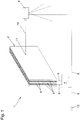
- Fig. 1 shows schematically and by way of example an overall structure of the arrangement, ie the detector device 1 including a shot source 9 in the form of a laser device, which is likewise shown here only in a highly simplified manner.
- a shot source 9 in the form of a laser device, which is likewise shown here only in a highly simplified manner.
- It can be Laser device so act in the shot source 9 shown here, for example, a laser welding robot or the like.
- the laser device is set in such a way that its laser beam 10 does not strike the flat structure 2 formed here as a wall. Incorrect control or the like can, however, result in the laser beam 10 being directed into areas into which it should not be directed.
- the detector device 1 is provided.
- the laser beam 10 strikes the wall-shaped structure 2 and the bundled energy of the laser beam 10 leads to a penetration 11 through the surface structure 2.
- the evaluation device 7 can then emit a corresponding warning signal to an optical, acoustic or whatever warning device 12 via one of the two signal outputs 8.
- the evaluation device 7 it is possible for the evaluation device 7 to send a shutdown signal to the laser device or the firing source 9 via a signal output 8, so that this laser device 9 is switched off immediately and further danger to man and machine is prevented thereby.
- a safety relay known per se can be used for an emergency stop.
- the evaluation device 7 In addition to the bullet or bullet 11, the evaluation device 7 also monitors, preferably permanently, whether the entire measuring facial expression with the measuring channels 5 and 6 is functioning properly. If there is a change in the monitored first or second electrical parameter in at least one of the measurement channels 5 and 6, regardless of a bullet 11 or a bullet in the fabric 2 due to a fault, such as a loose contact or a tearing cable or the like, then this is also determined by the evaluation device 7, so that a corresponding warning and / or shutdown signal submitted or another action can be taken.
- a corresponding sheet-like structure 2 can be designed not only as a wall but also as a curtain, for example in order to make an opening closable as easily as possible as a type of roller door. If a reclosable opening is required, this can also be achieved by means of at least one wall-shaped sheet 2 according to the invention, which is designed as a sliding gate.
- a laser cabin can be formed from a large number of such flat structures 2, with which the shot source 9 is preferably encased in its entirety in all required areas or directions.
- the detector device 1 according to the invention can also be used to detect bullets 11 or bullet holes by means of physical bodies such as projectiles, fragments and the like.
- the arrangements according to the invention can therefore also include or monitor completely different shot sources 9 than laser devices.
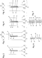
- a three-layer structure of the fabric 2 can be realized, as shown in the 2 and 3 is shown as an example.
- the invention provides that one of the electrically conductive layers 3 is arranged on a side of the electrically separating layer 4 or layers 4 facing the shot source 9 and another of the electrically conductive layers 3 is arranged on a side facing away from the shot source 9 the electrically separating layer 4 or Layers 4 is arranged.
- FIG. 1 While in Fig. 1 The measuring channels 5 and 6 and their connections to the electrically conductive layers 3 are shown only in a highly schematic manner in the FIGS 2 to 5 Various design variants are now shown, such as how the measuring channels 5 and 6 can be connected to the electrically conductive layers 3 in the case of three-layer and five-layer structures 2.
- the flat structure 2 is formed from two external electrically conductive layers 3 and an intermediate electrically separating layer 4.
- the electrically conductive layers 3 are in each case in direct contact with the electrically separating layer 4. Conveniently, it is in each case a full-area composite, so that the flat structure 2 as a whole forms a multi-layer body.
- two measuring channels 5 and 6 are provided. Each of the measuring channels 5 and 6 monitors a corresponding electrical parameter in one of the conductive layers 3. This takes place in the measuring channel 5 by tapping the measuring contacts 21 and 22 and in the measuring channel 6 by tapping the measuring contacts 23 and 24.
- the measuring contacts 21 to 24 can accordingly directly or indirectly to those in the 2 to 5 evaluation device 7, not shown again, may be connected.
- the monitoring of the first electrical parameter in measuring channel 5 and the second electrical parameter in measuring channel 6 is preferably carried out permanently during the operation of the shot source 9 to be monitored, ie here of the laser device.
- the monitored first and second electrical parameters in the individual measuring channels 5 and 6 can be, for example, an electrical current and / or an electrical voltage and / or an ohmic resistance.
- an electrical short circuit between the measurement channels 5 and 6 can also be detected.
- faults which are not caused by a bullet or bullet 11, such as a loose contact or a cable break or the like, can also occur are determined by the detector device 1 by at least one of the electrical parameters in the measuring channels 5 and 6 to be monitored indicating a deviation from a predefinable target value by more than a predefinable tolerance value or a short circuit between the measuring channels 5 and 6 due to a deviation in the first and / or second electrical parameter is determined. It is also determined if there is a bullet or bullet 11 through the fabric 2.
- a third measuring channel 27 is provided, which can also be connected to the evaluation device 7 via its measuring contacts 25 and 26, in order to additionally monitor a third electrical parameter in this third measuring channel 27.
- Fig. 4 it is now a five-layer structure.
- a central electrically conductive layer 3 and additionally two external electrically conductive layers 3.
- an electrically separating layer 4 Between each two electrically conductive layers 3 there is in turn an electrically separating layer 4.
- the two outer electrically conductive layers 3 are electrically connected in series with one another and belong to the same measuring channel 5, the first electrical parameters of which are tapped by the evaluation device 7 via the measuring contacts 21 and 22.
- the second measuring channel 6 is connected to the centrally arranged electrically conductive layer 3; its second electrical parameter is monitored by the evaluation device 7 via the electrical contacts 23 and 24.
- the evaluation device 7 monitors at least one electrical parameter in each of the two measurement channels 5 and 6.
- the evaluation device 7 can emit a warning and / or shutdown signal via a corresponding signal output 8.
- Fig. 5 An embodiment variant is shown, which is based on the variant according to Fig. 4 based.
- a third measuring channel 27 is created here, which monitors an electrical parameter between the measuring channels 5 and 6.
- the connections 25 and 26 of the corresponding measuring channel 27 can in turn be connected to the evaluation device 7.
- the measuring channels 5 and 6 are used to monitor that there is no malfunction in the overall system, that is to say both measuring channels 5 and 6 function perfectly.
- a resistance measurement can be carried out, for example, to monitor these measurement channels 5 and 6.
- the third measuring channel 27 is provided in preferred variants for detecting a bullet or bullet.
- the third electrical parameter monitored in it can also be an ohmic resistance or it can just as well be a short-circuit monitoring.
- Fig. 6 illustrates the situation of a bullet 11 through a three-layer structure, as shown in FIGS 2 and 3 is shown.
- a corresponding through-channel is created in the electrically separating layer 4, through which material of the external electrical layers is transported or melted, so that it is generally used for the direct electrically conductive connection of the two external electrically conductive layers Layers 3 and thus a short circuit occurs.
- the first and / or second electrical parameters monitored in the individual measuring channels 5 and 6 are changed significantly, which can be determined according to the invention by the evaluation device 7.
- Fig. 7 is the same situation for a five - layer structure as in the 4 and 5 is shown.
- melting of the electrically separating layers 4 and melting of the electrically conductive layers 3 leads to contact between the electrically conductive layers 3 of the different measuring channels 5 and 6 and thus to a corresponding deviation of the monitored or measured electrical parameters in at least one of the Measuring channels 5, 6 and 27, which in turn can be correspondingly detected by the evaluation device 7.
Landscapes
- Engineering & Computer Science (AREA)
- Physics & Mathematics (AREA)
- Optics & Photonics (AREA)
- Mechanical Engineering (AREA)
- Plasma & Fusion (AREA)
- General Engineering & Computer Science (AREA)
- Robotics (AREA)
- Investigating Or Analyzing Materials By The Use Of Electric Means (AREA)
Claims (11)
- Ensemble comportant au moins une source de tir (9) et au moins un dispositif de détection (1), dans lequel le dispositif de détection (1) présente au moins une structure plate (2) pour la détection d'au moins un tir pénétrant ou traversant (11) provoqué par la source de tir (9) dans ou à travers la structure plate (2) et au moins un dispositif d'évaluation (7), dans lequel la structure plate (2) présente au moins deux couches électriquement conductrices (3) et au moins une couche, électriquement séparatrice (4), en particulier isolante, dans lequel une des couches électriquement conductrices (3) est agencée sur un côté tourné vers la source de tir (9) de la couche électriquement séparatrice (4) et une autre des couches électriquement conductrices (3) est agencée sur un côté opposé à la source de tir (9) de la couche électriquement séparatrice (4) et dans lequel la couche électriquement séparatrice (4) présente une résistance ohmique spécifique plus élevée que les couches électriquement conductrices (3), caractérisé en ce que le dispositif de détection (1) présente au moins deux canaux de mesure (5, 6), dans lequel le dispositif d'évaluation (7) surveille, de préférence en permanence, avec un des canaux de mesure (5) au moins un premier paramètre électrique dans une des couches électriquement conductrices (3) et avec un autre des canaux de mesure (6) au moins un deuxième paramètre électrique dans une autre des couches électriquement conductrices (3) et le dispositif de détection (1) présente en outre un troisième canal de mesure (27), lequel surveille, de préférence en permanence, un troisième paramètre électrique entre l'un des canaux de mesure (5) et l'autre des canaux de mesure (6).
- Ensemble selon la revendication 1, caractérisé en ce que le dispositif d'évaluation (7) présente au moins une sortie de signal (8) pour la délivrance d'un signal d'avertissement et/ou de coupure.
- Ensemble selon la revendication 1 ou 2, caractérisé en ce que le premier et/ou le deuxième et/ou le troisième paramètre électrique est un courant électrique et/ou une tension électrique et/ou une résistance ohmique et/ou un court-circuit électrique entre les canaux de mesure (5, 6, 27).
- Ensemble selon l'une quelconque des revendications 1 à 3, caractérisé en ce que des couches électriquement conductrices (3) respectivement adjacentes les unes aux autres et séparées les unes des autres par une couche électriquement séparatrice (4) sont associées à des canaux de mesure (5, 6) différents les uns des autres.
- Ensemble selon l'une quelconque des revendications 1 à 4, caractérisé en ce que la structure plate (2) est un élément mural ou un rideau souple.
- Ensemble selon l'une quelconque des revendications 1 à 5, caractérisé en ce que la structure plate (2) présente au moins trois couches électriquement conductrices (3), dans lequel respectivement au moins une couche électriquement séparatrice (4) est agencée entre respectivement deux des couches électriquement conductrices (3) et une des couches électriquement conductrices (3) est agencée sur un côté tourné vers la source de tir (9) des couches électriquement séparatrices (4) et une autre des couches électriquement conductrices (3) est agencée sur un côté opposé à la source de tir (9) des couches électriquement séparatrices (4).
- Ensemble selon la revendication 6, caractérisé en ce que les deux couches extérieures des couches électriquement conductrices (3) sont reliées électriquement en série l'une avec l'autre et appartiennent au même canal de mesure (5), lequel surveille le premier paramètre électrique et/ou en ce que l'autre des canaux de mesure (6) est raccordé à la couche médiane des couches électriquement conductrices (3) et y surveille le deuxième paramètre électrique.
- Ensemble selon l'une quelconque des revendications 1 à 7, caractérisé en ce que les couches électriquement conductrices (3) s'appliquent respectivement directement sur la couche (4) ou les couches électriquement séparatrices (4) agencées à côté et/ou s'appliquent sur toute la surface avec une de leurs surfaces sur la couche (4) ou les couches électriquement séparatrices (4) agencées à côté, dans lequel les surfaces des couches électriquement conductrices (3) sont prédéfinies par leur longueur et largeur et l'épaisseur des couches électriquement conductrices (3) respectives est plus petite que leur longueur et que leur largeur.
- Ensemble selon l'une quelconque des revendications 1 à 8, caractérisé en ce que les couches électriquement conductrices (3) et la couche électriquement séparatrice (4) ou les couches électriquement séparatrices (4) sont reliées les unes aux autres, de préférence collées les unes aux autres et forment un corps multicouche cohérent en soi, de préférence sur toute la surface.
- Procédé de fonctionnement d'un ensemble selon l'une quelconque des revendications 1 à 9, caractérisé en ce que le premier paramètre électrique est surveillé, de préférence en permanence, dans une des couches conductrices (3) avec le dispositif d'évaluation (7) avec un des canaux de mesure (5) et le deuxième paramètre électrique est surveillé, de préférence en permanence, dans une autre des couches conductrices (3), avec un autre des canaux de mesure (6).
- Procédé selon la revendication 10, caractérisé en ce que le dispositif d'évaluation (7) présente une sortie de signal (8) et un signal d'avertissement et/ou de coupure est délivré par le dispositif d'évaluation (7) par le biais de la sortie de signal (8), lorsqu'un écart du premier et/ou deuxième paramètre électrique mesuré par rapport à une valeur de consigne pouvant être prédéfinie de plus d'une valeur de tolérance et/ou un court-circuit entre les canaux de mesure (5, 6) est constaté par le dispositif d'évaluation (7), conditionné par un tir pénétrant ou un tir traversant (11) dans ou à travers la structure plate (2) ou par une perturbation, dans au moins un des canaux de mesure (5, 6).
Priority Applications (1)
| Application Number | Priority Date | Filing Date | Title |
|---|---|---|---|
| PL16794202T PL3377801T3 (pl) | 2015-11-16 | 2016-10-20 | Układ z co najmniej jednym źródłem strzałów i z co najmniej jednym urządzeniem detekcyjnym |
Applications Claiming Priority (2)
| Application Number | Priority Date | Filing Date | Title |
|---|---|---|---|
| AT7292015 | 2015-11-16 | ||
| PCT/AT2016/000093 WO2017083890A1 (fr) | 2015-11-16 | 2016-10-20 | Ensemble comportant au moins une source de tir et au moins un dispositif de détection |
Publications (2)
| Publication Number | Publication Date |
|---|---|
| EP3377801A1 EP3377801A1 (fr) | 2018-09-26 |
| EP3377801B1 true EP3377801B1 (fr) | 2020-01-29 |
Family
ID=57280910
Family Applications (1)
| Application Number | Title | Priority Date | Filing Date |
|---|---|---|---|
| EP16794202.8A Active EP3377801B1 (fr) | 2015-11-16 | 2016-10-20 | Ensemble comportant au moins une source de tir et au moins un dispositif de détection |
Country Status (5)
| Country | Link |
|---|---|
| EP (1) | EP3377801B1 (fr) |
| CN (1) | CN108474516B (fr) |
| ES (1) | ES2784886T3 (fr) |
| PL (1) | PL3377801T3 (fr) |
| WO (1) | WO2017083890A1 (fr) |
Families Citing this family (2)
| Publication number | Priority date | Publication date | Assignee | Title |
|---|---|---|---|---|
| DE102024129699A1 (de) | 2024-10-14 | 2026-04-16 | Rheinmetall Protection Systems Gmbh | Ballistische Schutzplatte |
| DE102024129703A1 (de) | 2024-10-14 | 2026-04-16 | Rheinmetall Protection Systems Gmbh | Ballistische Schutzplatte |
Family Cites Families (11)
| Publication number | Priority date | Publication date | Assignee | Title |
|---|---|---|---|---|
| US3594770A (en) * | 1968-10-28 | 1971-07-20 | Lewis Eng Co | Printed-circuit type security apparatus for protecting areas |
| US3871739A (en) * | 1972-08-14 | 1975-03-18 | Gen Dynamics Corp | System for protection from laser radiation |
| US5151095A (en) * | 1989-11-22 | 1992-09-29 | Teeple Jr Edward | Laser shield with indicator means |
| DE19629037C1 (de) * | 1996-07-18 | 1997-07-31 | Erwin Martin Heberer | Wandelement für eine einen Arbeits- oder Wirkungsbereich umgebende Schutzvorrichtung gegen Laserstrahlen einer Laserquelle |
| US7154481B2 (en) * | 2002-06-25 | 2006-12-26 | 3M Innovative Properties Company | Touch sensor |
| CN201249331Y (zh) * | 2008-08-28 | 2009-06-03 | 宝山钢铁股份有限公司 | 加热温度自调节控制的激光热丝焊送丝装置 |
| DE102009023821A1 (de) * | 2009-06-04 | 2011-03-17 | Trautmann, Andreas | Schutzwandelement zur Abschirmung von Laserstrahlung und anderer hochenergetischer ionisierender bzw. nicht ionisierender Strahlung |
| EP2592326B1 (fr) * | 2011-11-09 | 2014-07-23 | Lasermet Limited | Système de sécurisation actif pour laser |
| DE102012106278B4 (de) * | 2012-04-13 | 2016-04-14 | Scansonic Mi Gmbh | Laserschutzvorrichtung zum Erfassen von Laserstrahlung |
| CN202719356U (zh) * | 2012-07-31 | 2013-02-06 | 张安民 | 具有外挂防护罩的电焊机 |
| JP2015119072A (ja) * | 2013-12-19 | 2015-06-25 | 富士電機株式会社 | レーザ溶接方法、レーザ溶接治具、半導体装置 |
-
2016
- 2016-10-20 ES ES16794202T patent/ES2784886T3/es active Active
- 2016-10-20 WO PCT/AT2016/000093 patent/WO2017083890A1/fr not_active Ceased
- 2016-10-20 PL PL16794202T patent/PL3377801T3/pl unknown
- 2016-10-20 CN CN201680066974.7A patent/CN108474516B/zh active Active
- 2016-10-20 EP EP16794202.8A patent/EP3377801B1/fr active Active
Non-Patent Citations (1)
| Title |
|---|
| None * |
Also Published As
| Publication number | Publication date |
|---|---|
| WO2017083890A1 (fr) | 2017-05-26 |
| EP3377801A1 (fr) | 2018-09-26 |
| CN108474516B (zh) | 2021-05-25 |
| PL3377801T3 (pl) | 2020-07-27 |
| ES2784886T3 (es) | 2020-10-01 |
| CN108474516A (zh) | 2018-08-31 |
Similar Documents
| Publication | Publication Date | Title |
|---|---|---|
| DE102018129158B4 (de) | Sicherheitsvorrichtung für eine Batterie | |
| EP0777928B1 (fr) | Disjoncteur a courant de defaut pourvu d'un dispositif de surveillance automatique | |
| DE102015224658B4 (de) | Elektromechanischer Schutzschalter | |
| DE102012106277B4 (de) | Laserschutzvorrichtung zum Abschirmen von Laserstrahlung | |
| EP2642582A2 (fr) | Elément de pontage électrique, notamment pour les cellules d'un accumulateur d'énergie | |
| EP3385007B1 (fr) | Dispositif à pièce d'usure et dispositif de mesure d'usure | |
| WO2009019020A1 (fr) | Élément de conversion de protection laser pour un carter de protection dans des installations de traitement au laser | |
| EP3377801B1 (fr) | Ensemble comportant au moins une source de tir et au moins un dispositif de détection | |
| EP2711488A2 (fr) | Poignée de portière de véhicule automobile à électronique de capteur | |
| WO2020069697A1 (fr) | Procédé pour déterminer un court-circuit à l'apparition d'un arc électrique sur un conducteur électrique | |
| DE102013220760A1 (de) | Kurzschlussdetektionsvorrichtung zur Detektion von Kurzschlüssen einer Batteriezelle und Verfahren zur Kurzschlussdetektion | |
| DE102014017990A1 (de) | Hochvoltkomponente für ein Fahrzeug, insbesondere ein Hybrid- oder Elektrofahrzeug | |
| EP3245694B1 (fr) | Procédé de catégorisation d'un arc électrique ou de détection d'un arc électrique parasite | |
| DE4244546C2 (de) | Elektromagnetisches Sandwich | |
| EP3095123B1 (fr) | Dispositif de commutation pour commuter des courants électriques élevés et système de batteries équipé d'un tel dispositif de commutation | |
| EP3724624B1 (fr) | Appareil pour déterminer et/ou surveiller la température | |
| DE102012008974B4 (de) | Kraftfahrzeug, insbesondere umfassend ein Hochvolt-System | |
| DE102020113498A1 (de) | Verfahren und Vorrichtung zum Überwachen einer Batteriezellen-Anordnung, Batteriezellen-Anordnung und Verwendung bei einem Fahrzeug, insbesondere Luftfahrzeug | |
| DE3431634C1 (de) | Verfahren und Vorrichtung zum Erzeugen eines Signales bei Durchtritt eines Körpers durch eine Kontaktfolie | |
| EP1464786A1 (fr) | Bordure à interrupteur ainsi qu'un procédé et dispositif pour la production de cette bordure à interrupteur | |
| DE102021123979A1 (de) | Batteriegehäuseanordnung, Batterie und Verfahren zum Detektieren eines Defekts einer Batterie | |
| WO2011138025A1 (fr) | Dispositif de protection d'un objet au moins contre des jets de charge creuse | |
| DE102015009569A1 (de) | Elektrische Schutzschaltung zur Vermeidung eines thermischen Events einer Batteriezelle einer Kraftfahrzeugbatterie | |
| DE102014206366A1 (de) | Verfahren zur Prüfung eines Selbsthaltemagneten eines Schalters und Prüfeinrichtung für den Selbsthaltemagneten | |
| DE102019125133B4 (de) | System zum neutralisieren von oberflächenladungen und verfahren zum überwachen der funktionssicherheit eines solchen systems |
Legal Events
| Date | Code | Title | Description |
|---|---|---|---|
| STAA | Information on the status of an ep patent application or granted ep patent |
Free format text: STATUS: UNKNOWN |
|
| STAA | Information on the status of an ep patent application or granted ep patent |
Free format text: STATUS: THE INTERNATIONAL PUBLICATION HAS BEEN MADE |
|
| PUAI | Public reference made under article 153(3) epc to a published international application that has entered the european phase |
Free format text: ORIGINAL CODE: 0009012 |
|
| STAA | Information on the status of an ep patent application or granted ep patent |
Free format text: STATUS: REQUEST FOR EXAMINATION WAS MADE |
|
| 17P | Request for examination filed |
Effective date: 20180423 |
|
| AK | Designated contracting states |
Kind code of ref document: A1 Designated state(s): AL AT BE BG CH CY CZ DE DK EE ES FI FR GB GR HR HU IE IS IT LI LT LU LV MC MK MT NL NO PL PT RO RS SE SI SK SM TR |
|
| AX | Request for extension of the european patent |
Extension state: BA ME |
|
| DAV | Request for validation of the european patent (deleted) | ||
| DAX | Request for extension of the european patent (deleted) | ||
| STAA | Information on the status of an ep patent application or granted ep patent |
Free format text: STATUS: EXAMINATION IS IN PROGRESS |
|
| 17Q | First examination report despatched |
Effective date: 20190516 |
|
| GRAP | Despatch of communication of intention to grant a patent |
Free format text: ORIGINAL CODE: EPIDOSNIGR1 |
|
| STAA | Information on the status of an ep patent application or granted ep patent |
Free format text: STATUS: GRANT OF PATENT IS INTENDED |
|
| INTG | Intention to grant announced |
Effective date: 20191001 |
|
| GRAS | Grant fee paid |
Free format text: ORIGINAL CODE: EPIDOSNIGR3 |
|
| GRAJ | Information related to disapproval of communication of intention to grant by the applicant or resumption of examination proceedings by the epo deleted |
Free format text: ORIGINAL CODE: EPIDOSDIGR1 |
|
| GRAL | Information related to payment of fee for publishing/printing deleted |
Free format text: ORIGINAL CODE: EPIDOSDIGR3 |
|
| STAA | Information on the status of an ep patent application or granted ep patent |
Free format text: STATUS: EXAMINATION IS IN PROGRESS |
|
| GRAR | Information related to intention to grant a patent recorded |
Free format text: ORIGINAL CODE: EPIDOSNIGR71 |
|
| STAA | Information on the status of an ep patent application or granted ep patent |
Free format text: STATUS: GRANT OF PATENT IS INTENDED |
|
| GRAA | (expected) grant |
Free format text: ORIGINAL CODE: 0009210 |
|
| STAA | Information on the status of an ep patent application or granted ep patent |
Free format text: STATUS: THE PATENT HAS BEEN GRANTED |
|
| INTC | Intention to grant announced (deleted) | ||
| INTG | Intention to grant announced |
Effective date: 20191211 |
|
| AK | Designated contracting states |
Kind code of ref document: B1 Designated state(s): AL AT BE BG CH CY CZ DE DK EE ES FI FR GB GR HR HU IE IS IT LI LT LU LV MC MK MT NL NO PL PT RO RS SE SI SK SM TR |
|
| REG | Reference to a national code |
Ref country code: GB Ref legal event code: FG4D Free format text: NOT ENGLISH |
|
| REG | Reference to a national code |
Ref country code: CH Ref legal event code: EP |
|
| REG | Reference to a national code |
Ref country code: AT Ref legal event code: REF Ref document number: 1228750 Country of ref document: AT Kind code of ref document: T Effective date: 20200215 |
|
| REG | Reference to a national code |
Ref country code: IE Ref legal event code: FG4D Free format text: LANGUAGE OF EP DOCUMENT: GERMAN |
|
| REG | Reference to a national code |
Ref country code: DE Ref legal event code: R096 Ref document number: 502016008572 Country of ref document: DE |
|
| REG | Reference to a national code |
Ref country code: SE Ref legal event code: TRGR |
|
| REG | Reference to a national code |
Ref country code: DE Ref legal event code: R082 Ref document number: 502016008572 Country of ref document: DE Representative=s name: DR. WEITZEL & PARTNER PATENT- UND RECHTSANWAEL, DE |
|
| REG | Reference to a national code |
Ref country code: NL Ref legal event code: MP Effective date: 20200129 Ref country code: SK Ref legal event code: T3 Ref document number: E 34095 Country of ref document: SK |
|
| PG25 | Lapsed in a contracting state [announced via postgrant information from national office to epo] |
Ref country code: PT Free format text: LAPSE BECAUSE OF FAILURE TO SUBMIT A TRANSLATION OF THE DESCRIPTION OR TO PAY THE FEE WITHIN THE PRESCRIBED TIME-LIMIT Effective date: 20200621 Ref country code: NO Free format text: LAPSE BECAUSE OF FAILURE TO SUBMIT A TRANSLATION OF THE DESCRIPTION OR TO PAY THE FEE WITHIN THE PRESCRIBED TIME-LIMIT Effective date: 20200429 Ref country code: FI Free format text: LAPSE BECAUSE OF FAILURE TO SUBMIT A TRANSLATION OF THE DESCRIPTION OR TO PAY THE FEE WITHIN THE PRESCRIBED TIME-LIMIT Effective date: 20200129 Ref country code: RS Free format text: LAPSE BECAUSE OF FAILURE TO SUBMIT A TRANSLATION OF THE DESCRIPTION OR TO PAY THE FEE WITHIN THE PRESCRIBED TIME-LIMIT Effective date: 20200129 |
|
| REG | Reference to a national code |
Ref country code: LT Ref legal event code: MG4D |
|
| PG25 | Lapsed in a contracting state [announced via postgrant information from national office to epo] |
Ref country code: BG Free format text: LAPSE BECAUSE OF FAILURE TO SUBMIT A TRANSLATION OF THE DESCRIPTION OR TO PAY THE FEE WITHIN THE PRESCRIBED TIME-LIMIT Effective date: 20200429 Ref country code: LV Free format text: LAPSE BECAUSE OF FAILURE TO SUBMIT A TRANSLATION OF THE DESCRIPTION OR TO PAY THE FEE WITHIN THE PRESCRIBED TIME-LIMIT Effective date: 20200129 Ref country code: IS Free format text: LAPSE BECAUSE OF FAILURE TO SUBMIT A TRANSLATION OF THE DESCRIPTION OR TO PAY THE FEE WITHIN THE PRESCRIBED TIME-LIMIT Effective date: 20200529 Ref country code: HR Free format text: LAPSE BECAUSE OF FAILURE TO SUBMIT A TRANSLATION OF THE DESCRIPTION OR TO PAY THE FEE WITHIN THE PRESCRIBED TIME-LIMIT Effective date: 20200129 Ref country code: GR Free format text: LAPSE BECAUSE OF FAILURE TO SUBMIT A TRANSLATION OF THE DESCRIPTION OR TO PAY THE FEE WITHIN THE PRESCRIBED TIME-LIMIT Effective date: 20200430 |
|
| PG25 | Lapsed in a contracting state [announced via postgrant information from national office to epo] |
Ref country code: NL Free format text: LAPSE BECAUSE OF FAILURE TO SUBMIT A TRANSLATION OF THE DESCRIPTION OR TO PAY THE FEE WITHIN THE PRESCRIBED TIME-LIMIT Effective date: 20200129 |
|
| REG | Reference to a national code |
Ref country code: ES Ref legal event code: FG2A Ref document number: 2784886 Country of ref document: ES Kind code of ref document: T3 Effective date: 20201001 |
|
| PG25 | Lapsed in a contracting state [announced via postgrant information from national office to epo] |
Ref country code: DK Free format text: LAPSE BECAUSE OF FAILURE TO SUBMIT A TRANSLATION OF THE DESCRIPTION OR TO PAY THE FEE WITHIN THE PRESCRIBED TIME-LIMIT Effective date: 20200129 Ref country code: LT Free format text: LAPSE BECAUSE OF FAILURE TO SUBMIT A TRANSLATION OF THE DESCRIPTION OR TO PAY THE FEE WITHIN THE PRESCRIBED TIME-LIMIT Effective date: 20200129 Ref country code: RO Free format text: LAPSE BECAUSE OF FAILURE TO SUBMIT A TRANSLATION OF THE DESCRIPTION OR TO PAY THE FEE WITHIN THE PRESCRIBED TIME-LIMIT Effective date: 20200129 Ref country code: SM Free format text: LAPSE BECAUSE OF FAILURE TO SUBMIT A TRANSLATION OF THE DESCRIPTION OR TO PAY THE FEE WITHIN THE PRESCRIBED TIME-LIMIT Effective date: 20200129 Ref country code: EE Free format text: LAPSE BECAUSE OF FAILURE TO SUBMIT A TRANSLATION OF THE DESCRIPTION OR TO PAY THE FEE WITHIN THE PRESCRIBED TIME-LIMIT Effective date: 20200129 |
|
| REG | Reference to a national code |
Ref country code: DE Ref legal event code: R097 Ref document number: 502016008572 Country of ref document: DE |
|
| PLBE | No opposition filed within time limit |
Free format text: ORIGINAL CODE: 0009261 |
|
| STAA | Information on the status of an ep patent application or granted ep patent |
Free format text: STATUS: NO OPPOSITION FILED WITHIN TIME LIMIT |
|
| 26N | No opposition filed |
Effective date: 20201030 |
|
| PG25 | Lapsed in a contracting state [announced via postgrant information from national office to epo] |
Ref country code: SI Free format text: LAPSE BECAUSE OF FAILURE TO SUBMIT A TRANSLATION OF THE DESCRIPTION OR TO PAY THE FEE WITHIN THE PRESCRIBED TIME-LIMIT Effective date: 20200129 |
|
| REG | Reference to a national code |
Ref country code: CH Ref legal event code: PL |
|
| PG25 | Lapsed in a contracting state [announced via postgrant information from national office to epo] |
Ref country code: LU Free format text: LAPSE BECAUSE OF NON-PAYMENT OF DUE FEES Effective date: 20201020 Ref country code: MC Free format text: LAPSE BECAUSE OF FAILURE TO SUBMIT A TRANSLATION OF THE DESCRIPTION OR TO PAY THE FEE WITHIN THE PRESCRIBED TIME-LIMIT Effective date: 20200129 |
|
| REG | Reference to a national code |
Ref country code: BE Ref legal event code: MM Effective date: 20201031 |
|
| PG25 | Lapsed in a contracting state [announced via postgrant information from national office to epo] |
Ref country code: LI Free format text: LAPSE BECAUSE OF NON-PAYMENT OF DUE FEES Effective date: 20201031 Ref country code: CH Free format text: LAPSE BECAUSE OF NON-PAYMENT OF DUE FEES Effective date: 20201031 Ref country code: BE Free format text: LAPSE BECAUSE OF NON-PAYMENT OF DUE FEES Effective date: 20201031 |
|
| PG25 | Lapsed in a contracting state [announced via postgrant information from national office to epo] |
Ref country code: IE Free format text: LAPSE BECAUSE OF NON-PAYMENT OF DUE FEES Effective date: 20201020 |
|
| PG25 | Lapsed in a contracting state [announced via postgrant information from national office to epo] |
Ref country code: TR Free format text: LAPSE BECAUSE OF FAILURE TO SUBMIT A TRANSLATION OF THE DESCRIPTION OR TO PAY THE FEE WITHIN THE PRESCRIBED TIME-LIMIT Effective date: 20200129 Ref country code: MT Free format text: LAPSE BECAUSE OF FAILURE TO SUBMIT A TRANSLATION OF THE DESCRIPTION OR TO PAY THE FEE WITHIN THE PRESCRIBED TIME-LIMIT Effective date: 20200129 Ref country code: CY Free format text: LAPSE BECAUSE OF FAILURE TO SUBMIT A TRANSLATION OF THE DESCRIPTION OR TO PAY THE FEE WITHIN THE PRESCRIBED TIME-LIMIT Effective date: 20200129 |
|
| PG25 | Lapsed in a contracting state [announced via postgrant information from national office to epo] |
Ref country code: MK Free format text: LAPSE BECAUSE OF FAILURE TO SUBMIT A TRANSLATION OF THE DESCRIPTION OR TO PAY THE FEE WITHIN THE PRESCRIBED TIME-LIMIT Effective date: 20200129 Ref country code: AL Free format text: LAPSE BECAUSE OF FAILURE TO SUBMIT A TRANSLATION OF THE DESCRIPTION OR TO PAY THE FEE WITHIN THE PRESCRIBED TIME-LIMIT Effective date: 20200129 |
|
| P01 | Opt-out of the competence of the unified patent court (upc) registered |
Effective date: 20231117 |
|
| PGFP | Annual fee paid to national office [announced via postgrant information from national office to epo] |
Ref country code: GB Payment date: 20231024 Year of fee payment: 8 |
|
| PGFP | Annual fee paid to national office [announced via postgrant information from national office to epo] |
Ref country code: SE Payment date: 20231023 Year of fee payment: 8 Ref country code: AT Payment date: 20231017 Year of fee payment: 8 |
|
| PGFP | Annual fee paid to national office [announced via postgrant information from national office to epo] |
Ref country code: PL Payment date: 20231017 Year of fee payment: 8 |
|
| PGFP | Annual fee paid to national office [announced via postgrant information from national office to epo] |
Ref country code: CZ Payment date: 20241016 Year of fee payment: 9 |
|
| REG | Reference to a national code |
Ref country code: SE Ref legal event code: EUG |
|
| REG | Reference to a national code |
Ref country code: AT Ref legal event code: MM01 Ref document number: 1228750 Country of ref document: AT Kind code of ref document: T Effective date: 20241020 |
|
| GBPC | Gb: european patent ceased through non-payment of renewal fee |
Effective date: 20241020 |
|
| PG25 | Lapsed in a contracting state [announced via postgrant information from national office to epo] |
Ref country code: GB Free format text: LAPSE BECAUSE OF NON-PAYMENT OF DUE FEES Effective date: 20241020 |
|
| PG25 | Lapsed in a contracting state [announced via postgrant information from national office to epo] |
Ref country code: AT Free format text: LAPSE BECAUSE OF NON-PAYMENT OF DUE FEES Effective date: 20241020 |
|
| PG25 | Lapsed in a contracting state [announced via postgrant information from national office to epo] |
Ref country code: SE Free format text: LAPSE BECAUSE OF NON-PAYMENT OF DUE FEES Effective date: 20241021 |
|
| PGFP | Annual fee paid to national office [announced via postgrant information from national office to epo] |
Ref country code: ES Payment date: 20260324 Year of fee payment: 10 |
|
| PGFP | Annual fee paid to national office [announced via postgrant information from national office to epo] |
Ref country code: DE Payment date: 20260320 Year of fee payment: 10 |
|
| PGFP | Annual fee paid to national office [announced via postgrant information from national office to epo] |
Ref country code: IT Payment date: 20260323 Year of fee payment: 10 |
|
| PGFP | Annual fee paid to national office [announced via postgrant information from national office to epo] |
Ref country code: FR Payment date: 20260320 Year of fee payment: 10 |
|
| PGFP | Annual fee paid to national office [announced via postgrant information from national office to epo] |
Ref country code: SK Payment date: 20260324 Year of fee payment: 10 |