EP3377861B1 - Methode de calibration in-situ d'une voie de transmission analogue et appareil correspondant - Google Patents
Methode de calibration in-situ d'une voie de transmission analogue et appareil correspondant Download PDFInfo
- Publication number
- EP3377861B1 EP3377861B1 EP16788473.3A EP16788473A EP3377861B1 EP 3377861 B1 EP3377861 B1 EP 3377861B1 EP 16788473 A EP16788473 A EP 16788473A EP 3377861 B1 EP3377861 B1 EP 3377861B1
- Authority
- EP
- European Patent Office
- Prior art keywords
- control
- evaluation unit
- analog electrical
- sensor
- simulation mode
- Prior art date
- Legal status (The legal status is an assumption and is not a legal conclusion. Google has not performed a legal analysis and makes no representation as to the accuracy of the status listed.)
- Active
Links
Images


Classifications
-
- G—PHYSICS
- G01—MEASURING; TESTING
- G01D—MEASURING NOT SPECIALLY ADAPTED FOR A SPECIFIC VARIABLE; ARRANGEMENTS FOR MEASURING TWO OR MORE VARIABLES NOT COVERED IN A SINGLE OTHER SUBCLASS; TARIFF METERING APPARATUS; MEASURING OR TESTING NOT OTHERWISE PROVIDED FOR
- G01D18/00—Testing or calibrating apparatus or arrangements provided for in groups G01D1/00 - G01D15/00
- G01D18/002—Automatic recalibration
- G01D18/006—Intermittent recalibration
-
- G—PHYSICS
- G01—MEASURING; TESTING
- G01K—MEASURING TEMPERATURE; MEASURING QUANTITY OF HEAT; THERMALLY-SENSITIVE ELEMENTS NOT OTHERWISE PROVIDED FOR
- G01K15/00—Testing or calibrating of thermometers
- G01K15/005—Calibration
Definitions
- the invention relates to a method for in-situ calibration of an analog measurement transmission path during the determination and / or monitoring of a process variable of a medium, analog electrical signals being transmitted via the measurement transmission path from a control / evaluation unit to a control unit.
- the control / evaluation unit is assigned to a sensor.
- the sensor determines and / or monitors the process variable based on at least one component sensitive to the process variable.
- the process variable may include temperature, density, viscosity, pressure, level, flow, chemical composition, temperature, or analytical data, such as pH, turbidity, or conductivity of a medium.
- Corresponding sensors are offered and distributed by the E + H Group in a wide variety of designs.
- the medium may be, for example, a liquid or a gas.
- the analog electrical signals are, for example, currents, voltages or capacitances.
- the invention relates to a device whose components are designed to carry out the method.
- the measured values of a sensor are provided to the user during operation via a communication infrastructure of a control unit located outside the sensor. This is done, for example, by a wireless or a wired digital communication infrastructure.
- the measured value transmission and the energy supply of the sensor are carried out via a two-wire cable. This is particularly important in the fields of automation technology, in which there are restrictions on the energy supplied to the sensor, which is always the case when sensors are used in potentially explosive atmospheres.
- the standardized measuring ranges of 0-20mA and 4-20mA exist according to DIN IEC 60381-1.
- the measuring range of 4-20mA has the advantage over the 0-20mA measuring range that wire monitoring is possible, as a signal of 0mA is a sure indication of a fault. In automation technology, therefore, the 4-20mA standard has become established.
- the Highway Addressable Remote Transducer (HART) method is a standardized, widely used digital communication system based on the 4-20mA standard for power transmission.
- a digital signal is generated by modulating a high-frequency oscillation at 1.2kHz and 2.2kHz on the analogue signal. Even such a HART interface, which allows the additional transmission of digital information via an analog current measurement transmission path, is not always available in practice.
- the sensor has a control / evaluation unit, which controls the at least one sensitive component of the sensor, evaluates the measured value of the at least one sensitive component and generates an analog electrical signal representing the process variable.
- the analog electrical signal is then provided via the analog measurement transmission path of the control unit located outside the sensor.
- the control unit is arranged, for example, in a control room or is connected to a control room.
- the electrical signal originates from a value range designated as useful range. The effective range is selected so that it corresponds to the maximum and minimum process variables assumed in the process.
- the user parameterizes the measuring transmission path so that the effective range selected for the process is a true subset of the standardized measuring range.
- a real subset means that the working range is within the standardized measuring range, but there are also areas of the measuring range that are not accepted during the process, since they are below or above the working range.
- the US 4532601 A1 describes calibration of electrical lines without having to disconnect them. This is done by feeding a reference voltage whose effect is calculated out by a microprocessor on the measured values transmitted with it
- the DE 10 2011 107 856 A1 discloses in situ calibration of a resistance based thermometer. Here, a separate calibration unit is used with an additional thermometer.
- the invention has for its object to provide a method and an apparatus that allow an in-situ calibration of the measuring transmission path.
- the object is achieved according to the invention by operating the sensor either in a measuring mode or in a simulation mode.
- the control / evaluation unit converts the measured values of the at least one sensitive component of the sensor into the analog electrical signal.
- the control / evaluation unit outputs at least one clearly identifiable as a simulated analog electrical signal for a fixed period of time, which is detected and detected by the control unit.
- the measurement transmission path is calibrated in that the control unit determines the deviation between the analog electrical signal specified by the control / evaluation unit and the detected analog electrical signal.
- the detected analog electrical signal in the control unit is additionally corrected accordingly.
- the core of the invention is thus that the sensor can be operated both in the measuring mode, as well as in the simulation mode and in the simulation mode, the analog measurement transmission path is calibrated. As a result, the sensor no longer needs to be removed to calibrate the measurement transmission path.
- the in-situ calibration of the analog measurement transmission path is made possible by a suitable embodiment of the control unit and the control / evaluation unit of the sensor.
- a calibration of the measurement transmission path can be realized and displayed by the control / evaluation unit outputting at least one constant simulated analog electrical signal to the measurement transmission path for a defined period of time.
- An advantageous embodiment of the method according to the invention is that a plurality of simulated constant electrical signals are output successively in certain time periods.
- the constant signals differ by a certain amount from the constant electrical signal in the previous period of time, for example by a fixed positive contribution, at any given time.
- This covers the standardized measuring range of the measuring transmission path in a ramp profile.
- the ramp profile is a non-continuous signal-time function.
- a variant provides to cover the measuring range by a strictly monotonically increasing signal-time function.
- the signal-time function may be, for example, linear or logarithmic. Further possible embodiments for suitable signal time functions covering the measuring range are close to the person skilled in the art.
- Another advantage of the invention is that on the basis of the simulation mode of the sensor via the analog measurement transmission path additional information about the state of the sensor is transmitted, which is obtained within the control / evaluation of the sensor, and in known methods only via a digital communication infrastructure or means of the HART protocol.
- the deviation between the predetermined by the control / evaluation unit analog electrical signal and the detected on the control unit analog electrical signal is stored. This allows, for example, the automatic creation of a calibration protocol for calibrating the measurement transmission path. Alternatively, the value is not stored in the control unit itself, but in a separate memory unit connected to the control unit.
- the simulation mode can be displayed by the control / evaluation unit of the control unit by outputting a preset pattern of analog electrical signals to the measurement transmission path from the control / evaluation unit.
- the signals come from a defined range of values.
- the preset pattern is defined by outputting sequences of constant currents for defined periods of time.
- the control / evaluation unit of the sensor is designed such that it outputs the pattern in the simulation mode.
- the control unit is designed such that it recognizes from the preset pattern of analog electrical signals that the sensor is operated in simulation mode.
- measuring transmission lines which use standardized measuring ranges also have standardized alarm limits. If a signal is detected at the control unit, which is smaller than the lower standardized alarm limit S min , so a first alarm is triggered (low alarm). If a signal is detected at the control unit which is greater than the upper standardized alarm limit S max , then a different second alarm is triggered (high alarm).
- the value range of the analog electrical signals used to display the simulation mode is within the range [S min , S max ] or within the alarm limits of the measurement transmission path. If 4-20mA currents and the NAMUR recommendation NE43 are used, the range for displaying the simulation mode in this advantageous embodiment is therefore the interval between 3.8mA and 20.5mA.
- the range of values of the analog electrical signals which is used to display the simulation mode is selected such that it has no overlap with the useful range. Since the payload is a true subset of the measurement range, the unused range of the range [S min , S max ] can be used to display the simulation mode. In this advantageous embodiment, therefore, exactly the area for displaying the simulation mode is used, which is not used in the measuring mode during the measurement of the process variable.
- the control / evaluation unit of the sensor automatically performs a change to the simulation mode during the measurement of the process variable.
- the condition for this is that at least one sensitive component assumes a certain value. It is thus possible to specify one or more values for the process variable at which the sensor changes to the simulation mode.
- the condition for the change to the simulation mode is defined by a combination of the measured values of several sensitive components.
- the determined value (s) at which a change to the simulation mode is triggered is / are, for example, adjustable by the user on the basis of one or more parameters.
- the control / evaluation unit is able to create a good message, a warning message and / or an error message about the state of the sensor in the simulation mode and to transmit it via the measurement transmission path.
- the good message is output from a first preset pattern of analog electrical signals.
- the warning message is output from a second pattern of analog electrical signals other than the first pattern.
- the error message is output from a third preset pattern of analog electrical signals, different from the first and second patterns.
- the good message, warning message and / or error message is transmitted via the measuring transmission path.
- the control unit recognizes on the basis of the received, preset and distinguishable patterns, whether it is a good message, a warning message, and / or an error message.
- the range for displaying the good and warning message lies just within the alarm limits or within the value range [S min , S max ].
- the analogue electrical signals for displaying the error message are outside [S min , S max ].
- the good and / or warning message can then be stored in the control unit or stored in a separate memory unit connected to the control unit.
- the at least one sensitive component of the sensor also transmits its measured value in the simulation mode of the control / evaluation unit.
- the control / evaluation unit in the simulation mode no longer transmits the measured value to the control unit via the measuring transmission path.
- the control / evaluation unit is also in simulation mode in a position, a Error message to trigger if the measured variables of one or more sensitive components of the sensor exceeds and / or falls below critical values for the process variable. These critical values are defined within the control / evaluation unit.
- the method according to the invention thus makes it possible, for example, to simultaneously transmit a good message and to continue to monitor the process variable in parallel so that a warning or error message is also generated in the control / evaluation unit in the simulation mode.
- the temperature-sensitive component measures a temperature of 120 ° C. and at the same time to allow the control / evaluation unit to monitor during the calibration of the measurement transmission path that the temperature always exceeds 120 ° C. or fallen below.
- Full compliance with a monitoring temperature is of great importance for hygienic requirements in the food and / or pharmaceutical sector.
- the method of the present application also allows seamless monitoring of the temperature in the simulation mode.
- An error message from the sensor can only be rectified by manual intervention on the sensor and / or the measuring transmission path.
- a further development of the invention provides that the sensor is again placed in the measuring mode after issuing a good and / or warning message.
- the change from the operation of the sensor in the measuring mode to the operation of the sensor in the simulation mode for in-situ calibration of the measuring transmission path, as well as the return change from the operation of the sensor in the simulation mode for operating the sensor in the measuring mode can be done completely automatically in the present invention.
- the change to the simulation mode can be triggered by the fact that at least one sensitive component assumes a value, and the return to the measurement mode follows automatically after the good and / or warning message.
- a further development provides that the change to the simulation mode can also be done manually.
- a power interruption may cause the change to the simulation mode and the in-situ calibration of the measurement transmission path. Since a power interruption occurs during the commissioning of the sensor, this represents a particularly advantageous development, since thus the calibration of the measuring transmission path is part of the routine for commissioning the sensor.
- Other ways of manual intervention to change to simulation mode are triggering a switch located on the sensor.
- a contactless release is possible, which is actuated from outside by a magnet, for example by a reed relay or a Hall probe in Sensor.
- a contactless triggering is a short-range radio link with the sensor, for example in the infrared range, by Bluetooth, or by near-field communication.
- Other such manual contactless releases are obvious to those skilled in the art.
- the sensor must be designed so that it has an additional, capable of contactless triggering device.
- the method according to the invention therefore also provides that the user of the sensor can determine whether the changeover to the simulation mode takes place automatically or by means of a manual intervention.
- the invention includes a device for in-situ calibration of an analog measurement transmission path during the determination and / or monitoring of a process variable of a medium, wherein the device is designed for carrying out the method.
- the device has a sensor and a control unit, wherein the sensor has at least one sensitive component and a control / evaluation unit, and wherein the control / evaluation unit is connected to the control unit via the measurement transmission path.
- the senor is a thermometer, wherein the sensor has a temperature-sensitive component and a reference element which undergoes a phase transformation at at least one predetermined temperature point.
- the control / evaluation unit calibrates the temperature-sensitive component based on the reference element at the fixed temperature point by determining the deviation of the first temperature-sensitive component from the temperature point predetermined by the reference element.
- Such in-situ calibrating thermometer is in the DE 10 2010 040 039 disclosed.
- the control / evaluation unit causes a change from the measurement mode in the simulation mode when the predetermined temperature point is traversed.
- thermometer If an in-situ calibrating thermometer is operated together with an analog measurement transmission path, the measurement transmission path must also be calibrated at regular intervals during long-term operation. To calibrate the measuring transmission path, the thermometer must then be removed again. The technical advantage of a self-calibrating and validating thermometer would thus be partially canceled when using an analog measurement transmission path.
- the present application thus makes it possible to carry out both an in-situ calibration of the thermometer and an in-situ calibration of the analog measurement transmission path. In this advantageous embodiment of the device, the present invention thus allows all technical advantages of in-situ even if the dedicated digital communication infrastructure or HART interface is not available.
- the simulation mode can be used to transmit the information obtained during the calibration of the temperature-sensitive component of the sensor via the analog measurement transmission path.
- the control / evaluation unit outputs a constant electrical signal for a defined time, which corresponds to the deviation of the temperature-sensitive component from the temperature point predetermined by the reference element.
- the user can set, for example, based on a parameter when commissioning the sensor, a specific constant electrical signal, in which the deviation of the temperature-sensitive component is displayed by the predetermined by the reference element temperature point.
- the control unit thus recognizes the deviation of the temperature-sensitive component from the temperature point predetermined by the reference element on the basis of the deviation of the constant electrical signal output by the control / evaluation unit from the specified analog electrical signal and on the basis of the parameterization of the measurement transmission path.
- the deviation of the temperature-sensitive component from the temperature point predetermined by the reference element is also stored in the control unit after transmission via the measuring transmission path.
- the deviation may also be stored in a separate memory unit connected to the control unit.
- the device of the disclosure DE 10 2009 058 282 a sensor with two temperature-sensitive components, wherein the two temperature-sensitive component are calibrated.
- the simulation mode of the sensor can be used in a manner obvious to that described above.
- the control / evaluation unit of the sensor can transmit a drift of the two temperature-sensitive components via the analog measurement transmission path.
- the invention can be generalized to other sensors that measure process variables other than temperature. If an in-situ calibration of the sensor is carried out (for example by using a plurality of sensitive components) and if an analog measurement transmission path is used, then the present invention can also be applied mutatis mutandis to such devices.
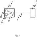
- Fig. 1 shows the schematic arrangement of the sensor 2, the measuring transmission path 1 and control unit 3, and the different sensor components.
- the sensor contains at least one sensitive component 22 and a control / evaluation unit 21.
- the signal direction of the analog electrical signal is directed from the control / evaluation unit 21 via the measuring transmission path 1 to the control unit 3.
- the sensitive component 22 consists of a temperature sensor.
- a reference element 23 is used to calibrate the first temperature-sensitive component 22.
- the calibration of the sensor takes place at a fixed temperature point at which the reference element 23 undergoes a phase transition.
- the simulation mode for calibrating the measurement transmission path 1 can then preferably be triggered by passing through the fixed temperature point for calibrating the sensor 2. Then, both the sensor 2 and the analog measuring transmission path 1 are calibrated one after the other. Subsequently, the information determined during the calibration can be transmitted in each case for the sensor 2 and the measurement transmission path 1 and documented in individual and / or common, automatically generated calibration protocols.
- Fig. 2 shows a ramp profile, as it could be used in the simulation mode for the calibration of the measuring transmission path 1 in the period between t 1 and t 2 .
- the measuring range 5 is spanned by S a and S c .
- the ramp profile scans the entire measuring range 5. This is done in the example shown in that, for defined periods of time, in each case constant signals S a , S b and S c are output by the control / evaluation unit 21, where S a is smaller than S b and S b is smaller than S c . Since the control unit 3 is designed so that the profile issued by the control / evaluation unit 21 is known to it, the control unit 3 can calibrate the measurement transmission path. In a variant, all subsequent signals are still corrected accordingly
- the control / evaluation unit 21 then outputs the deviation of the first temperature-sensitive component from the temperature point predetermined by the reference element 23. It is determined at which signal the deviation is to be output (dashed line).
- This specified signal can be set by the user.
- One possibility is to set the signal at which the deviation is output when the sensor is put into operation. For example, the user can set a parameter to a specific value.
- the control unit can determine the deviation .DELTA.S and then convert this into a temperature difference based on the parameterization and the calibration of the measurement transmission path. The temperature difference can then be stored and / or stored in a calibration log.
- Fig. 3 shows the relevant signal ranges of the analog electrical signal and their position relative to each other.
- the control unit 3 triggers a first alarm when it detects a current whose value is smaller than 3.8mA and a second alarm different from the first alarm when it detects a current whose value is larger than 20.5mA.
- the range between 3.8mA and 20.5mA can be used to display the simulation mode.
- the useful range 4 is included in the measuring range.
- the working area is chosen so that it corresponds to the maximum and minimally accepted process variables in the process. It is a true subset of the measurement range. This means that there are always unused areas in the measuring range.
- the standardized current range of 4-20mA parameterizes the temperature range of 50-180 ° C, but only minimum temperatures of 80 ° C and maximum temperatures of 150 ° C are achieved in the application. Therefore, there is an unused signal range included in the measurement range.
- the unused signal range is a first signal range corresponding to the temperature between 50-80 ° C, and a second signal range corresponding to Temperature between 150-180 ° C corresponds.
- This unused signal range can be used in the present application preferably for displaying the simulation mode.
- the lower bound of the first unused (lower) signal region is still extended to 3.8mA
- the upper bound of the second unused (upper) signal region is expanded to 20.5mA.
- the pattern of signals for displaying the simulation mode is then preferably chosen such that values from the lower and the upper unused range are output alternately from the control / evaluation unit. The idea here is to unambiguously recognize the simulation mode by outputting a signal sequence from the control / evaluation unit, which occurs with negligible probability in the measurement mode.
Landscapes
- Physics & Mathematics (AREA)
- General Physics & Mathematics (AREA)
- Arrangements For Transmission Of Measured Signals (AREA)
Claims (15)
- Procédé destiné à l'étalonnage in-situ d'une section de transmission de mesure analogique (1) pendant la détermination et/ou la surveillance d'une grandeur process dans un produit, des signaux électriques analogiques étant transmis, via la section de transmission de mesure (1), d'une unité de régulation / d'exploitation (21) vers une unité de commande (3),
l'unité de régulation / d'exploitation (21) étant attribuée à un capteur (2), qui détermine et/ou surveille la grandeur de process au moyen d'au moins un composant sensible (22) à la grandeur de process,
le capteur (2) étant utilisé soit dans un mode de mesure, soit dans un mode de simulation,
procédé pour lequel, en mode de mesure, l'unité de régulation / d'exploitation (21) convertit les valeurs mesurées de l'au moins un composant sensible (22) du capteur (2) en un signal électrique analogique représentant la grandeur de process,
procédé pour lequel, en mode de simulation, l'unité de régulation / d'exploitation (21) émet pendant un intervalle de temps défini au moins un signal électrique analogique clairement identifiable comme étant simulé, lequel signal est détecté et mesuré par l'unité de commande (3),
et procédé pour lequel, en mode de simulation, l'étalonnage de la section de transmission de mesure (1) est effectué en ce que l'unité de commande (3) détermine l'écart entre le signal électrique analogique prédéfini par l'unité de régulation / d'exploitation (21) et le signal électrique analogique mesuré. - Procédé selon la revendication 1,
pour lequel, en mode de simulation, l'écart entre le signal électrique analogique prédéfini par l'unité de régulation / d'exploitation (21) et le signal électrique analogique mesuré sur l'unité de commande (3) est enregistré. - Procédé selon la revendication 1 ou 2,
pour lequel, en mode de simulation, l'unité de régulation / d'exploitation (21) émet un échantillon préréglé de signaux électriques analogiques à partir d'une gamme de valeurs définie de façon fixe, et pour lequel l'unité de commande (3) détecte, au moyen de l'échantillon préréglé de signaux électriques analogiques, que le capteur (2) est utilisé en mode de simulation. - Procédé selon au moins l'une des revendications précédentes,
pour lequel l'unité de commande (3) déclenche une première alarme dans le cas où elle détecte un signal dont la valeur est inférieure à un signal électrique analogique minimal Smin,
pour lequel l'unité de commande (3) déclenche une deuxième alarme différente de la première alarme dans le cas où elle détecte un signal dont la valeur est supérieure à un signal électrique analogique maximal Smax. - Procédé selon la revendication 3 et 4,
pour lequel la gamme de valeurs définie de façon fixe, laquelle est utilisée par l'unité de régulation / d'exploitation (21) pour l'affichage du mode de simulation, se situe à l'intérieur de la gamme [Smin, Smax]. - Procédé selon la revendication 4 et 5,
pour lequel les signaux électriques analogiques émis en mode de mesure proviennent d'une gamme de valeurs appelée gamme utile (4),
la gamme utile (4) étant paramétrée de telle sorte à ce qu'elle corresponde aux grandeurs de process maximales et minimales prises en compte dans le process, la gamme utile (4) étant un sous-ensemble réel de [Smin, Smax],
et la gamme de valeurs, qui est utilisée par l'unité de régulation / d'exploitation (21) pour l'affichage du mode de simulation, ne présentant aucun chevauchement avec la gamme utile (4). - Procédé selon au moins l'une des revendications précédentes,
pour lequel un passage dans le mode de simulation est effectué lorsqu'au moins un composant sensible (22) du capteur (2) adopte au moins une valeur définie. - Procédé selon au moins l'une des revendications précédentes,
pour lequel, en mode de simulation, un message OK, un message d'avertissement et/ou un message d'erreur est émis sur l'état du capteur (2), l'unité de régulation / d'exploitation (21) émettant, dans le cas d'un message OK, un premier échantillon préréglé de signaux électriques analogiques,
l'unité de régulation / d'exploitation (21) émettant, dans le cas d'un message d'avertissement, un deuxième échantillon préréglé de signaux électriques analogiques, lequel est différent du premier échantillon,
l'unité de régulation / d'exploitation (21) émettant, dans le cas d'un message d'erreur, un troisième échantillon préréglé de signaux électriques analogiques, lequel est différent du premier et du deuxième échantillon,
les signaux électriques analogiques destinés à l'affichage du message OK et du message d'avertissement se situant dans la gamme de valeurs [Smin, Smax],
et les signaux électriques analogiques destinés à l'affichage du message d'erreur se situant en dehors de la gamme de valeurs [Smin, Smax],
et le message OK et/ou le message d'avertissement étant enregistrés. - Procédé selon la revendication 8,
pour lequel le capteur (2) est remis en mode de mesure après l'émission du message OK et/ou du message d'avertissement. - Procédé selon au moins l'une des revendications précédentes,
pour lequel un passage dans le mode de simulation est déclenché manuellement, de préférence par une interruption de la tension du capteur (2), par l'actionnement d'un interrupteur magnétique et/ou par communication en champ proche. - Dispositif destiné à l'étalonnage in-situ d'une section de transmission de mesure analogique (1) pendant la détermination et/ou la surveillance d'une grandeur de process d'un produit, le dispositif pour la réalisation du procédé selon au moins l'une des revendications 1 à 10 étant constitué
d'un capteur (2) et d'une unité de commande,
le capteur (2) comportant au minimum un composant sensible (22) et une unité de régulation / d'exploitation (21),
et l'unité de régulation / d'exploitation (21) étant reliée avec l'unité de commande (3) via la section de transmission de mesure (1). - Dispositif selon la revendication 11,
pour lequel le capteur (2) comporte un composant sensible à la température (22) et un élément de référence (23), lequel subit une transition de phase au niveau d'au moins un point de température prédéfini,
l'unité de régulation / d'exploitation (21) étalonnant au niveau du point de température fixe le composant sensible à la température (22) au moyen de l'élément de référence (23) et déterminant l'écart du composant sensible à la température (22) par rapport au point de température prédéfini par l'élément de référence (23),
et l'unité de régulation / d'exploitation (21) provoquant un passage du mode de mesure dans le mode de simulation lorsque l'élément de référence (23) parcourt le point de température prédéfini. - Dispositif selon la revendication 12,
pour lequel l'unité de régulation / d'exploitation (21) émet, dans le mode de simulation, après l'étalonnage du composant sensible à la température (22) et de la section de transmission de mesure (1), pendant un temps déterminé, un signal électrique analogique constant qui correspond à l'écart du composant sensible à la température (22) par rapport au point de référence prédéfini par l'élément de référence (23) ;
l'unité de commande (3) détectant au moyen de l'écart ΔS du signal électrique constant émis par l'unité de régulation / d'exploitation (21) par rapport à un signal électrique analogique défini, et au moyen du paramétrage de la section de transmission de mesure (1), l'écart du composant sensible à la température (22) par rapport au point de température prédéfini par l'élément de référence (23). - Dispositif selon la revendication 13,
pour lequel l'unité de commande (3) enregistre, dans le mode de simulation, l'écart du composant sensible à la température (22) par rapport au point de température prédéfini par l'élément de référence (23). - Dispositif selon la revendication 13 ou 14,
pour lequel l'unité de régulation / d'exploitation (21) génère un message OK dans le cas où l'écart du composant sensible à la température (22) par rapport au point de température prédéfini par l'élément de référence (23) passe sous un seuil défini,
et pour lequel l'unité de régulation / d'exploitation (21) génère un message d'avertissement dans le cas où l'écart du composant sensible à la température (22) par rapport au point de température prédéfini par l'élément de référence (23) dépasse un seuil défini.
Applications Claiming Priority (2)
| Application Number | Priority Date | Filing Date | Title |
|---|---|---|---|
| DE102015120072.4A DE102015120072A1 (de) | 2015-11-19 | 2015-11-19 | Verfahren zur in-situ Kalibrierung einer analogen Messübertragungsstrecke und entsprechende Vorrichtung |
| PCT/EP2016/075322 WO2017084828A1 (fr) | 2015-11-19 | 2016-10-21 | Procédé d'étalonnage in-situ d'une ligne de transmission de mesure analogique et dispositif correspondant |
Publications (2)
| Publication Number | Publication Date |
|---|---|
| EP3377861A1 EP3377861A1 (fr) | 2018-09-26 |
| EP3377861B1 true EP3377861B1 (fr) | 2019-09-04 |
Family
ID=57211492
Family Applications (1)
| Application Number | Title | Priority Date | Filing Date |
|---|---|---|---|
| EP16788473.3A Active EP3377861B1 (fr) | 2015-11-19 | 2016-10-21 | Methode de calibration in-situ d'une voie de transmission analogue et appareil correspondant |
Country Status (5)
| Country | Link |
|---|---|
| US (1) | US10989574B2 (fr) |
| EP (1) | EP3377861B1 (fr) |
| CN (1) | CN108291825B (fr) |
| DE (1) | DE102015120072A1 (fr) |
| WO (1) | WO2017084828A1 (fr) |
Families Citing this family (4)
| Publication number | Priority date | Publication date | Assignee | Title |
|---|---|---|---|---|
| DE102015115535A1 (de) * | 2015-09-15 | 2017-03-16 | Endress + Hauser Wetzer Gmbh + Co Kg | Verfahren zur Kalibrierung eines in einem Prozess der Automatisierungstechnik befindlichen Temperatursensors |
| DE102018122014A1 (de) * | 2018-09-10 | 2020-03-12 | Endress + Hauser Flowtec Ag | Meßgeräte-System sowie damit gebildete Meßanordnung |
| DE102019107625A1 (de) * | 2018-12-20 | 2020-06-25 | Endress+Hauser Conducta Gmbh+Co. Kg | Verfahren zur In-Prozess-Justage eines potentiometrischen Sensors einer Messanordnung |
| DE102019134019A1 (de) * | 2019-12-11 | 2021-06-17 | Endress + Hauser Wetzer Gmbh + Co. Kg | In situ Kalibrierung eines Thermometers |
Family Cites Families (16)
| Publication number | Priority date | Publication date | Assignee | Title |
|---|---|---|---|---|
| US4532601A (en) * | 1982-08-19 | 1985-07-30 | Westinghouse Electric Corp. | Automatic temperature calibration method and apparatus |
| DE4121637C2 (de) * | 1991-06-29 | 1997-04-24 | Bosch Gmbh Robert | Verfahren zur Prüfung von Steuergeräten und Prüfeinrichtung zur Durchführung des Verfahrens |
| US20030158683A1 (en) * | 2002-02-19 | 2003-08-21 | Claude Gauthier | Temperature calibration using on-chip electrical fuses |
| DE102005041427A1 (de) * | 2005-08-31 | 2007-03-01 | Endress + Hauser Conducta Gesellschaft für Mess- und Regeltechnik mbH + Co. KG | Sensorsimulator |
| CN101334308B (zh) * | 2007-06-29 | 2013-03-27 | 通用电气公司 | 用于检测流量计的仿真电路 |
| US7715669B2 (en) * | 2007-10-17 | 2010-05-11 | Avago Technologies Fiber Ip (Singapore) Pte. Ltd. | Fiber optic link, a transceiver for use in the link, and methods for designing and constructing fiber optic links and transceivers |
| DE102008050612A1 (de) * | 2008-10-09 | 2010-04-15 | Endress + Hauser Conducta Gesellschaft für Mess- und Regeltechnik mbH + Co. KG | Verfahren zum Testen des Verhaltens einer Prozessanlage |
| PL2216635T3 (pl) * | 2009-02-06 | 2019-12-31 | Mettler-Toledo Gmbh | Urządzenie kalibrujące dla urządzenia do pomiaru siły i urządzenie do pomiaru siły |
| DE102009058282B3 (de) | 2009-12-14 | 2011-02-17 | Temperaturmeßtechnik Geraberg GmbH | Vorrichtung und Verfahren zur Temperaturmessung |
| DE102010040039A1 (de) | 2010-08-31 | 2012-03-01 | Endress + Hauser Wetzer Gmbh + Co Kg | Verfahren und Vorrichtung zur in situ Kalibrierung eines Thermometers |
| DE102011107856A1 (de) * | 2011-07-18 | 2013-01-24 | Abb Technology Ag | Temperatursensor mit Mitteln zur in-situ Kalibrierung |
| US20130144549A1 (en) | 2011-12-01 | 2013-06-06 | Grigori Temkine | Method for calibrating temperature sensors using reference voltages |
| DE102012103464A1 (de) * | 2012-04-19 | 2013-10-24 | Brose Fahrzeugteile Gmbh & Co. Kommanditgesellschaft, Hallstadt | Stellantrieb einer Luftdurchlassvorrichtung und Verfahren zur Steuerung eines Stellantriebs |
| US20140200840A1 (en) * | 2012-12-19 | 2014-07-17 | Instrument Works Pty Ltd | Platform for Portable Sensing Applications |
| DE102012112782A1 (de) * | 2012-12-20 | 2014-06-26 | Endress + Hauser Conducta Gesellschaft für Mess- und Regeltechnik mbH + Co. KG | Verfahren und Vorrichtung zur Bestimmung eines Zustands eines in einem Prozessbehälter integrierten Messaufnehmers |
| DE102013100799A1 (de) * | 2012-12-21 | 2014-06-26 | Endress + Hauser Flowtec Ag | Umformerschaltung mit einer Stromschnittstelle sowie Meßgerät mit einer solchen Umformerschaltung |
-
2015
- 2015-11-19 DE DE102015120072.4A patent/DE102015120072A1/de not_active Ceased
-
2016
- 2016-10-21 CN CN201680065409.9A patent/CN108291825B/zh active Active
- 2016-10-21 EP EP16788473.3A patent/EP3377861B1/fr active Active
- 2016-10-21 US US15/777,280 patent/US10989574B2/en active Active
- 2016-10-21 WO PCT/EP2016/075322 patent/WO2017084828A1/fr not_active Ceased
Non-Patent Citations (1)
| Title |
|---|
| None * |
Also Published As
| Publication number | Publication date |
|---|---|
| WO2017084828A1 (fr) | 2017-05-26 |
| US20180328765A1 (en) | 2018-11-15 |
| EP3377861A1 (fr) | 2018-09-26 |
| CN108291825A (zh) | 2018-07-17 |
| US10989574B2 (en) | 2021-04-27 |
| DE102015120072A1 (de) | 2017-05-24 |
| CN108291825B (zh) | 2020-06-12 |
Similar Documents
| Publication | Publication Date | Title |
|---|---|---|
| EP2246984B1 (fr) | Appareil de diagnostic destinée au contrôle d'un appareil de conversion analogique-numérique | |
| EP1241438B1 (fr) | Dispositif de mesure d'angle | |
| EP3377861B1 (fr) | Methode de calibration in-situ d'une voie de transmission analogue et appareil correspondant | |
| DE102009026998A1 (de) | Leitfähigkeitssensor mit Umschaltung zwischen Sende- und Empfangsspule | |
| DE102013107904A1 (de) | Messgerät mit einer umschaltbaren Mess- und Betriebselektronik zur Übermittlung eines Messsignals | |
| EP2220460A2 (fr) | Dispositif de champ pour l'instrumentation d'un processus | |
| EP1091199B1 (fr) | Procédé et dispositif pour le test fonctionnel d'un interrupteur de limite | |
| DE102005048601B3 (de) | Vorrichtung und Verfahren zum fehlersicheren Auswerten eines Stellungsgebers, insbesondere eines Potentiometers | |
| WO2016165928A1 (fr) | Procédé de branchement ou de débranchement automatique d'une résistance de communication d'un dispositif hart | |
| DE10318171C5 (de) | Verfahren zur funktionsüberwachten Bestimmung einer Ventilstellung sowie ein in diesem Verfahren verwendbarer Ventilstellungsaufnehmer und Verwendung desselben | |
| EP3983853B1 (fr) | Appareil de terrain de la technique de l'automatisation | |
| WO2008138888A1 (fr) | Dispositif de contrôle de signaux pour une utilisation temporaire dans un appareil de champ en technique d'automatisation de procédés | |
| WO2012041593A2 (fr) | Procédé de récupération destiné à un appareil comportant une sortie de courant analogique pour l'émission d'une valeur de mesure ou d'une valeur de réglage | |
| WO2018114193A1 (fr) | Circuit électronique conçu pour un appareil de terrain de technique d'automation | |
| EP2747049B1 (fr) | Système de mesure pour la détermination d'une grandeur de mesure et procédé de génération d'un signal de sortie | |
| WO2010040628A2 (fr) | Procédé pour tester le comportement d'une installation de traitement | |
| DE102011050007B4 (de) | Stellungsregler | |
| EP3807733B1 (fr) | Diagnostic d'un appareil de terrain à deux conducteurs | |
| EP0496254A1 (fr) | Dispositif de mesure pour mesurer électriquement la résistance et méthode pour cela | |
| DE102005029045A1 (de) | Vorrichtung und Verfahren zur Bestimmung und/oder Überwachung der Temperatur | |
| DE102005051795A1 (de) | Anzeigeeinheit für die Prozessautomatisierungstechnik | |
| EP3830656B1 (fr) | Appareil de terrain bifilaire de la technique d'automatisation | |
| EP3153938B1 (fr) | Dispositif de mesure | |
| DE102015114211A1 (de) | Sensorschaltung zum Auswerten eines Sensorsignals | |
| EP3076249B1 (fr) | Procédé de fonctionnement d'un appareil de terrain et appareil de terrain correspondant |
Legal Events
| Date | Code | Title | Description |
|---|---|---|---|
| STAA | Information on the status of an ep patent application or granted ep patent |
Free format text: STATUS: UNKNOWN |
|
| STAA | Information on the status of an ep patent application or granted ep patent |
Free format text: STATUS: THE INTERNATIONAL PUBLICATION HAS BEEN MADE |
|
| PUAI | Public reference made under article 153(3) epc to a published international application that has entered the european phase |
Free format text: ORIGINAL CODE: 0009012 |
|
| STAA | Information on the status of an ep patent application or granted ep patent |
Free format text: STATUS: REQUEST FOR EXAMINATION WAS MADE |
|
| 17P | Request for examination filed |
Effective date: 20180410 |
|
| AK | Designated contracting states |
Kind code of ref document: A1 Designated state(s): AL AT BE BG CH CY CZ DE DK EE ES FI FR GB GR HR HU IE IS IT LI LT LU LV MC MK MT NL NO PL PT RO RS SE SI SK SM TR |
|
| AX | Request for extension of the european patent |
Extension state: BA ME |
|
| DAV | Request for validation of the european patent (deleted) | ||
| DAX | Request for extension of the european patent (deleted) | ||
| GRAP | Despatch of communication of intention to grant a patent |
Free format text: ORIGINAL CODE: EPIDOSNIGR1 |
|
| STAA | Information on the status of an ep patent application or granted ep patent |
Free format text: STATUS: GRANT OF PATENT IS INTENDED |
|
| INTG | Intention to grant announced |
Effective date: 20190426 |
|
| GRAS | Grant fee paid |
Free format text: ORIGINAL CODE: EPIDOSNIGR3 |
|
| GRAA | (expected) grant |
Free format text: ORIGINAL CODE: 0009210 |
|
| STAA | Information on the status of an ep patent application or granted ep patent |
Free format text: STATUS: THE PATENT HAS BEEN GRANTED |
|
| AK | Designated contracting states |
Kind code of ref document: B1 Designated state(s): AL AT BE BG CH CY CZ DE DK EE ES FI FR GB GR HR HU IE IS IT LI LT LU LV MC MK MT NL NO PL PT RO RS SE SI SK SM TR |
|
| REG | Reference to a national code |
Ref country code: GB Ref legal event code: FG4D Free format text: NOT ENGLISH |
|
| REG | Reference to a national code |
Ref country code: CH Ref legal event code: EP |
|
| REG | Reference to a national code |
Ref country code: AT Ref legal event code: REF Ref document number: 1176014 Country of ref document: AT Kind code of ref document: T Effective date: 20190915 |
|
| REG | Reference to a national code |
Ref country code: DE Ref legal event code: R096 Ref document number: 502016006471 Country of ref document: DE |
|
| REG | Reference to a national code |
Ref country code: IE Ref legal event code: FG4D Free format text: LANGUAGE OF EP DOCUMENT: GERMAN |
|
| REG | Reference to a national code |
Ref country code: NL Ref legal event code: MP Effective date: 20190904 |
|
| REG | Reference to a national code |
Ref country code: LT Ref legal event code: MG4D |
|
| PG25 | Lapsed in a contracting state [announced via postgrant information from national office to epo] |
Ref country code: SE Free format text: LAPSE BECAUSE OF FAILURE TO SUBMIT A TRANSLATION OF THE DESCRIPTION OR TO PAY THE FEE WITHIN THE PRESCRIBED TIME-LIMIT Effective date: 20190904 Ref country code: BG Free format text: LAPSE BECAUSE OF FAILURE TO SUBMIT A TRANSLATION OF THE DESCRIPTION OR TO PAY THE FEE WITHIN THE PRESCRIBED TIME-LIMIT Effective date: 20191204 Ref country code: HR Free format text: LAPSE BECAUSE OF FAILURE TO SUBMIT A TRANSLATION OF THE DESCRIPTION OR TO PAY THE FEE WITHIN THE PRESCRIBED TIME-LIMIT Effective date: 20190904 Ref country code: LT Free format text: LAPSE BECAUSE OF FAILURE TO SUBMIT A TRANSLATION OF THE DESCRIPTION OR TO PAY THE FEE WITHIN THE PRESCRIBED TIME-LIMIT Effective date: 20190904 Ref country code: FI Free format text: LAPSE BECAUSE OF FAILURE TO SUBMIT A TRANSLATION OF THE DESCRIPTION OR TO PAY THE FEE WITHIN THE PRESCRIBED TIME-LIMIT Effective date: 20190904 Ref country code: NO Free format text: LAPSE BECAUSE OF FAILURE TO SUBMIT A TRANSLATION OF THE DESCRIPTION OR TO PAY THE FEE WITHIN THE PRESCRIBED TIME-LIMIT Effective date: 20191204 |
|
| PG25 | Lapsed in a contracting state [announced via postgrant information from national office to epo] |
Ref country code: ES Free format text: LAPSE BECAUSE OF FAILURE TO SUBMIT A TRANSLATION OF THE DESCRIPTION OR TO PAY THE FEE WITHIN THE PRESCRIBED TIME-LIMIT Effective date: 20190904 Ref country code: LV Free format text: LAPSE BECAUSE OF FAILURE TO SUBMIT A TRANSLATION OF THE DESCRIPTION OR TO PAY THE FEE WITHIN THE PRESCRIBED TIME-LIMIT Effective date: 20190904 Ref country code: GR Free format text: LAPSE BECAUSE OF FAILURE TO SUBMIT A TRANSLATION OF THE DESCRIPTION OR TO PAY THE FEE WITHIN THE PRESCRIBED TIME-LIMIT Effective date: 20191205 Ref country code: RS Free format text: LAPSE BECAUSE OF FAILURE TO SUBMIT A TRANSLATION OF THE DESCRIPTION OR TO PAY THE FEE WITHIN THE PRESCRIBED TIME-LIMIT Effective date: 20190904 Ref country code: AL Free format text: LAPSE BECAUSE OF FAILURE TO SUBMIT A TRANSLATION OF THE DESCRIPTION OR TO PAY THE FEE WITHIN THE PRESCRIBED TIME-LIMIT Effective date: 20190904 |
|
| PG25 | Lapsed in a contracting state [announced via postgrant information from national office to epo] |
Ref country code: PT Free format text: LAPSE BECAUSE OF FAILURE TO SUBMIT A TRANSLATION OF THE DESCRIPTION OR TO PAY THE FEE WITHIN THE PRESCRIBED TIME-LIMIT Effective date: 20200106 Ref country code: NL Free format text: LAPSE BECAUSE OF FAILURE TO SUBMIT A TRANSLATION OF THE DESCRIPTION OR TO PAY THE FEE WITHIN THE PRESCRIBED TIME-LIMIT Effective date: 20190904 Ref country code: RO Free format text: LAPSE BECAUSE OF FAILURE TO SUBMIT A TRANSLATION OF THE DESCRIPTION OR TO PAY THE FEE WITHIN THE PRESCRIBED TIME-LIMIT Effective date: 20190904 Ref country code: EE Free format text: LAPSE BECAUSE OF FAILURE TO SUBMIT A TRANSLATION OF THE DESCRIPTION OR TO PAY THE FEE WITHIN THE PRESCRIBED TIME-LIMIT Effective date: 20190904 Ref country code: PL Free format text: LAPSE BECAUSE OF FAILURE TO SUBMIT A TRANSLATION OF THE DESCRIPTION OR TO PAY THE FEE WITHIN THE PRESCRIBED TIME-LIMIT Effective date: 20190904 |
|
| PG25 | Lapsed in a contracting state [announced via postgrant information from national office to epo] |
Ref country code: IS Free format text: LAPSE BECAUSE OF FAILURE TO SUBMIT A TRANSLATION OF THE DESCRIPTION OR TO PAY THE FEE WITHIN THE PRESCRIBED TIME-LIMIT Effective date: 20200224 Ref country code: SK Free format text: LAPSE BECAUSE OF FAILURE TO SUBMIT A TRANSLATION OF THE DESCRIPTION OR TO PAY THE FEE WITHIN THE PRESCRIBED TIME-LIMIT Effective date: 20190904 Ref country code: SM Free format text: LAPSE BECAUSE OF FAILURE TO SUBMIT A TRANSLATION OF THE DESCRIPTION OR TO PAY THE FEE WITHIN THE PRESCRIBED TIME-LIMIT Effective date: 20190904 Ref country code: CZ Free format text: LAPSE BECAUSE OF FAILURE TO SUBMIT A TRANSLATION OF THE DESCRIPTION OR TO PAY THE FEE WITHIN THE PRESCRIBED TIME-LIMIT Effective date: 20190904 |
|
| REG | Reference to a national code |
Ref country code: CH Ref legal event code: PL |
|
| REG | Reference to a national code |
Ref country code: DE Ref legal event code: R097 Ref document number: 502016006471 Country of ref document: DE |
|
| PLBE | No opposition filed within time limit |
Free format text: ORIGINAL CODE: 0009261 |
|
| STAA | Information on the status of an ep patent application or granted ep patent |
Free format text: STATUS: NO OPPOSITION FILED WITHIN TIME LIMIT |
|
| PG2D | Information on lapse in contracting state deleted |
Ref country code: IS |
|
| PG25 | Lapsed in a contracting state [announced via postgrant information from national office to epo] |
Ref country code: LI Free format text: LAPSE BECAUSE OF NON-PAYMENT OF DUE FEES Effective date: 20191031 Ref country code: CH Free format text: LAPSE BECAUSE OF NON-PAYMENT OF DUE FEES Effective date: 20191031 Ref country code: LU Free format text: LAPSE BECAUSE OF NON-PAYMENT OF DUE FEES Effective date: 20191021 Ref country code: DK Free format text: LAPSE BECAUSE OF FAILURE TO SUBMIT A TRANSLATION OF THE DESCRIPTION OR TO PAY THE FEE WITHIN THE PRESCRIBED TIME-LIMIT Effective date: 20190904 Ref country code: IS Free format text: LAPSE BECAUSE OF FAILURE TO SUBMIT A TRANSLATION OF THE DESCRIPTION OR TO PAY THE FEE WITHIN THE PRESCRIBED TIME-LIMIT Effective date: 20200105 |
|
| 26N | No opposition filed |
Effective date: 20200605 |
|
| REG | Reference to a national code |
Ref country code: BE Ref legal event code: MM Effective date: 20191031 |
|
| PG25 | Lapsed in a contracting state [announced via postgrant information from national office to epo] |
Ref country code: BE Free format text: LAPSE BECAUSE OF NON-PAYMENT OF DUE FEES Effective date: 20191031 Ref country code: MC Free format text: LAPSE BECAUSE OF FAILURE TO SUBMIT A TRANSLATION OF THE DESCRIPTION OR TO PAY THE FEE WITHIN THE PRESCRIBED TIME-LIMIT Effective date: 20190904 Ref country code: SI Free format text: LAPSE BECAUSE OF FAILURE TO SUBMIT A TRANSLATION OF THE DESCRIPTION OR TO PAY THE FEE WITHIN THE PRESCRIBED TIME-LIMIT Effective date: 20190904 |
|
| PG25 | Lapsed in a contracting state [announced via postgrant information from national office to epo] |
Ref country code: IE Free format text: LAPSE BECAUSE OF NON-PAYMENT OF DUE FEES Effective date: 20191021 |
|
| PG25 | Lapsed in a contracting state [announced via postgrant information from national office to epo] |
Ref country code: CY Free format text: LAPSE BECAUSE OF FAILURE TO SUBMIT A TRANSLATION OF THE DESCRIPTION OR TO PAY THE FEE WITHIN THE PRESCRIBED TIME-LIMIT Effective date: 20190904 |
|
| GBPC | Gb: european patent ceased through non-payment of renewal fee |
Effective date: 20201021 |
|
| PG25 | Lapsed in a contracting state [announced via postgrant information from national office to epo] |
Ref country code: MT Free format text: LAPSE BECAUSE OF FAILURE TO SUBMIT A TRANSLATION OF THE DESCRIPTION OR TO PAY THE FEE WITHIN THE PRESCRIBED TIME-LIMIT Effective date: 20190904 Ref country code: HU Free format text: LAPSE BECAUSE OF FAILURE TO SUBMIT A TRANSLATION OF THE DESCRIPTION OR TO PAY THE FEE WITHIN THE PRESCRIBED TIME-LIMIT; INVALID AB INITIO Effective date: 20161021 |
|
| PG25 | Lapsed in a contracting state [announced via postgrant information from national office to epo] |
Ref country code: GB Free format text: LAPSE BECAUSE OF NON-PAYMENT OF DUE FEES Effective date: 20201021 |
|
| PG25 | Lapsed in a contracting state [announced via postgrant information from national office to epo] |
Ref country code: TR Free format text: LAPSE BECAUSE OF FAILURE TO SUBMIT A TRANSLATION OF THE DESCRIPTION OR TO PAY THE FEE WITHIN THE PRESCRIBED TIME-LIMIT Effective date: 20190904 |
|
| PG25 | Lapsed in a contracting state [announced via postgrant information from national office to epo] |
Ref country code: MK Free format text: LAPSE BECAUSE OF FAILURE TO SUBMIT A TRANSLATION OF THE DESCRIPTION OR TO PAY THE FEE WITHIN THE PRESCRIBED TIME-LIMIT Effective date: 20190904 |
|
| REG | Reference to a national code |
Ref country code: AT Ref legal event code: MM01 Ref document number: 1176014 Country of ref document: AT Kind code of ref document: T Effective date: 20211021 |
|
| PG25 | Lapsed in a contracting state [announced via postgrant information from national office to epo] |
Ref country code: AT Free format text: LAPSE BECAUSE OF NON-PAYMENT OF DUE FEES Effective date: 20211021 |
|
| P01 | Opt-out of the competence of the unified patent court (upc) registered |
Effective date: 20230601 |
|
| PGFP | Annual fee paid to national office [announced via postgrant information from national office to epo] |
Ref country code: DE Payment date: 20251021 Year of fee payment: 10 |
|
| PGFP | Annual fee paid to national office [announced via postgrant information from national office to epo] |
Ref country code: IT Payment date: 20251024 Year of fee payment: 10 |
|
| PGFP | Annual fee paid to national office [announced via postgrant information from national office to epo] |
Ref country code: FR Payment date: 20251030 Year of fee payment: 10 |