EP3377948B1 - Ermöglichung der positionierung eines roboters - Google Patents
Ermöglichung der positionierung eines roboters Download PDFInfo
- Publication number
- EP3377948B1 EP3377948B1 EP16866952.1A EP16866952A EP3377948B1 EP 3377948 B1 EP3377948 B1 EP 3377948B1 EP 16866952 A EP16866952 A EP 16866952A EP 3377948 B1 EP3377948 B1 EP 3377948B1
- Authority
- EP
- European Patent Office
- Prior art keywords
- robot
- poses
- camera system
- indication
- indications
- Prior art date
- Legal status (The legal status is an assumption and is not a legal conclusion. Google has not performed a legal analysis and makes no representation as to the accuracy of the status listed.)
- Active
Links
Images


Classifications
-
- G—PHYSICS
- G06—COMPUTING OR CALCULATING; COUNTING
- G06T—IMAGE DATA PROCESSING OR GENERATION, IN GENERAL
- G06T7/00—Image analysis
- G06T7/70—Determining position or orientation of objects or cameras
- G06T7/73—Determining position or orientation of objects or cameras using feature-based methods
- G06T7/74—Determining position or orientation of objects or cameras using feature-based methods involving reference images or patches
-
- B—PERFORMING OPERATIONS; TRANSPORTING
- B25—HAND TOOLS; PORTABLE POWER-DRIVEN TOOLS; MANIPULATORS
- B25J—MANIPULATORS; CHAMBERS PROVIDED WITH MANIPULATION DEVICES
- B25J9/00—Program-controlled manipulators
- B25J9/16—Program controls
- B25J9/1679—Program controls characterised by the tasks executed
- B25J9/1692—Calibration of manipulator
-
- B—PERFORMING OPERATIONS; TRANSPORTING
- B25—HAND TOOLS; PORTABLE POWER-DRIVEN TOOLS; MANIPULATORS
- B25J—MANIPULATORS; CHAMBERS PROVIDED WITH MANIPULATION DEVICES
- B25J9/00—Program-controlled manipulators
- B25J9/16—Program controls
- B25J9/1694—Program controls characterised by use of sensors other than normal servo-feedback from position, speed or acceleration sensors, perception control, multi-sensor controlled systems, sensor fusion
- B25J9/1697—Vision controlled systems
-
- E—FIXED CONSTRUCTIONS
- E21—EARTH OR ROCK DRILLING; MINING
- E21C—MINING OR QUARRYING
- E21C35/00—Details of, or accessories for, machines for slitting or completely freeing the mineral from the seam, not provided for in groups E21C25/00 - E21C33/00, E21C37/00 or E21C39/00
- E21C35/08—Guiding the machine
-
- G—PHYSICS
- G05—CONTROLLING; REGULATING
- G05B—CONTROL OR REGULATING SYSTEMS IN GENERAL; FUNCTIONAL ELEMENTS OF SUCH SYSTEMS; MONITORING OR TESTING ARRANGEMENTS FOR SUCH SYSTEMS OR ELEMENTS
- G05B2219/00—Program-control systems
- G05B2219/30—Nc systems
- G05B2219/39—Robotics, robotics to robotics hand
- G05B2219/39057—Hand eye calibration, eye, camera on hand, end effector
-
- G—PHYSICS
- G06—COMPUTING OR CALCULATING; COUNTING
- G06T—IMAGE DATA PROCESSING OR GENERATION, IN GENERAL
- G06T2200/00—Indexing scheme for image data processing or generation, in general
- G06T2200/04—Indexing scheme for image data processing or generation, in general involving 3D image data
-
- G—PHYSICS
- G06—COMPUTING OR CALCULATING; COUNTING
- G06T—IMAGE DATA PROCESSING OR GENERATION, IN GENERAL
- G06T2207/00—Indexing scheme for image analysis or image enhancement
- G06T2207/10—Image acquisition modality
- G06T2207/10028—Range image; Depth image; 3D point clouds
-
- G—PHYSICS
- G06—COMPUTING OR CALCULATING; COUNTING
- G06T—IMAGE DATA PROCESSING OR GENERATION, IN GENERAL
- G06T2207/00—Indexing scheme for image analysis or image enhancement
- G06T2207/30—Subject of image; Context of image processing
- G06T2207/30244—Camera pose
-
- Y—GENERAL TAGGING OF NEW TECHNOLOGICAL DEVELOPMENTS; GENERAL TAGGING OF CROSS-SECTIONAL TECHNOLOGIES SPANNING OVER SEVERAL SECTIONS OF THE IPC; TECHNICAL SUBJECTS COVERED BY FORMER USPC CROSS-REFERENCE ART COLLECTIONS [XRACs] AND DIGESTS
- Y10—TECHNICAL SUBJECTS COVERED BY FORMER USPC
- Y10S—TECHNICAL SUBJECTS COVERED BY FORMER USPC CROSS-REFERENCE ART COLLECTIONS [XRACs] AND DIGESTS
- Y10S901/00—Robots
- Y10S901/02—Arm motion controller
- Y10S901/09—Closed loop, sensor feedback controls arm movement
Definitions
- aspects described herein relate generally to robotic three-dimensional scanning and robot positioning, for instance as used with industrial robotic systems that use a robot-mounted three-dimensional camera to scan a scene in an environment and then position the robot to/at features in the scanned scene to perform intended operations. More specifically, approaches for facilitating accurate robot positioning are disclosed. As an example, a sensor fusion approach is provided that combines robot position measurement ('robot odometry') with image registration method(s) ('visual odometry'), which can be used to automate camera-to-robot calibration and increase robot positioning accuracy. This is especially helpful for robotic applications in areas where the positions of objects or feature characteristics are unknown.
- FIG. 1 specifically depicts an example environment in which a robot performs work on a wall of unknown features.
- robot 102 includes a robot base 104 coupled to a robot mounting flange 108 via robot arms 106a, 106b, and 106c.
- Robot mounting flange 108 has tools mounted thereto, namely camera 110 and gripper 112.
- Robot 102 is adjacent wall 114.
- Robot 102 works on features of wall 114.
- wall 114 is a wall of rock
- the features are holes 116 in the rock
- the task of the robot is to fill each hole 116 with explosive materials.
- One application of this work is in mining operations where the work environment is extremely dangerous because of structural risks, poor lighting conditions, and other reasons.
- the scanned model of the scene typically represented in the form of a point cloud or a mesh model, can be readily imported into a computer-aided design (CAD) environment or other type of computer program for further processing.
- CAD computer-aided design
- the processing can be the identification and localization of features of interest so that the robot can move to the features to perform special operations. Additionally or alternatively, the processing can be generation of motion paths along which the robot can perform operations, such as painting or gluing.
- Three-dimensional scanning refers to the stitching of multiple camera views (images) to cover an entire scene.
- Stitching uses the measurement of relative camera position between the views, which can be provided by motion sensors such as GPS and encoders, or by the visual data itself.
- Scanning systems use an odometer to estimate the relative view positions in order to, e.g., stitch individual camera views together.
- visual Simultaneous Localization And Mapping (SLAM)-based 3D scanning systems rely on only the acquired visual data (visual odometry) to build the model using advanced registration methods. Kinect Fusion, developed by Microsoft Corporation, is one such example of visual SLAM.
- Visual odometry uses advanced computer algorithms, such as ICP (Iterative Closest Point) or SURF (SpeedUp Robust Features), in conjunction with RANSAC (RANdom Sampling And Consensus) to align the overlapped features on the camera views in order to determine the relative camera position.
- Visual odometry can work very well in registering feature-rich views.
- the robot itself is a position sensor and can serve as the odometer for the scanning.
- the camera tool center point (TCP) is accurately calibrated to obtain the correct camera position in robot space.
- Low-cost 3D cameras tend to be very noisy. Consequently, achieving accurate camera TCP calibration can be challenging.
- time-synchronization between the camera image acquisition and the robot position reading is ensured with high-accuracy.
- real time synchronization between the robot position reading and the camera image acquisition is not straightforward and necessitates tuning. This is not a trivial task if there is no built-in time-synchronization facility for the camera and for the robot controller.
- aspects described herein can automate the calibration step and increase robot positioning accuracy when moving to a feature on a scanned three-dimensional model.
- Both the robot based odometry and the visual odometry are leveraged to automate the robot-to-camera calibration.
- the camera position coordinates from the image registration and the robot position coordinates from the robot controller, together with their timestamps, are recorded at a fast sampling rate and stored during the scanning process.
- the scene may be stitched primarily with image registration method(s), but robot based odometry can be used when a feature-less region is encountered.
- the image registration method can output an index showing how well the registration method works, the index telling whether the scene is feature-rich or feature-poor.
- the feature position on the 3D scanned model can be detected in the scene space.
- the feature coordinates in the scene space can be converted to the robot space based on the recorded, dense pairs of the camera position coordinates and robot position coordinates. This can be done by estimating the camera TCP and the work object of the scene.
- the time delay between the camera acquisition and the robot position reading can be also estimated using the recorded time stamp information. Another possibility for improved accuracy is to estimate and use different camera TCPs and scene work objects across different scan regions.
- the task is to find the positions of the holes 116 in wall 114, then to drive the robot 102 to each hole 116 so that the robot mounted gripper 112 can be inserted into the hole 116.
- a 3D camera 110 is mounted on the robot mounting flange 108 as is the gripper tool 112. There are respective coordinate frames associated with each of the robot base 104, the robot mounting flange 108, the gripper 112, the camera 110, and the wall 114.
- Pose of an object refers to the position and orientation relative to some coordinate system. Pose can have many different but equivalent mathematical representations. For example, a six-component vector [x, y, z, roll, pitch, yaw] can represent translation in x, y, z and orientation in roll, pitch, yaw. In the examples described herein, a 4-by-4 (4x4) matrix is used only by way of specific example for simplicity, though any appropriate representation of pose is appropriate.
- the pose of a robot is expressed as the pose of its mounting flange ( T 0 ), and can be calculated from its joint measurement ⁇ as: where is the robot kinematic model parameters, including the arm (106) link lengths, the initial joint positions, and other factors.
- equation (1) provides the "nominal kinematics". Otherwise, equation (1) provides absolute accurate kinematics if the values of the factors are accurately measured or identified. Nominal kinematics has lower accuracy in determining the pose of a robot.
- the joint measurement ⁇ and the robot position T 0 can be read directly from the robot controller at a very fast sampling rate, for example every 4ms or so depending on system capabilities.
- T c T 0 ⁇ TCP c
- T g T 0 ⁇ TCP g
- TCP g T 0 ⁇ TCP g
- TCP c and T g are the poses of the camera 110 and the gripper 112, respectively, relative to the robot base 104.
- TCP or tool center point
- TCP g the relative pose of an object relative to the robot mounting flange.
- the tool center point of the camera i.e., the reference point of the camera system relative to the robot mounting flange
- TCP g the tool center point of the gripper relative to the robot mounting flange
- the TCP of the tool is calibrated.
- a mechanical tool such as a gripper
- its TCP can be calibrated using a commonly known four-point method where the tool tip is moved to touch a fixed point from four different angles.
- the camera frame is defined as the reference frame for its acquired image and is typically invisible. Commonly used methods for calibration are manual calibration or automated 'hand-eye' calibration.
- H c the feature pose in camera space (relative to the camera frame)
- H r the feature pose in robot space (relative to the robot base).
- Eq. (3) above is the basis for manual calibration, where a feature pattern with known position in robot space is placed in the view of the camera and the features in the image space are detected.
- Scanning using a 3D camera takes multiple images and merges them into a scene.
- This scene has a reference coordinate frame, W , whose pose relative to the robot base frame is called the 'work object' of the scene. It is often defined as the pose of the camera frame at the first shot in relation to the robot base frame. Stitching of the shots relies on the relative camera poses of those shots. Image registration can produce these relative poses using advanced vison algorithms, while, in contrast, robot based odometry (measured robot positions) provides them by using equation (2).
- T v ( t ) be the relative camera pose generated by the visual odometry at time instant t in reference to W (e.g. the 1 st camera pose).
- the pose of the camera system relative to reference coordinate frame W is determined based on a comparison of multiple three-dimensional images of a scene of the environment. It is noted that the pose can be determined absent prior knowledge of the characteristics of the features of the scene, such as the distances between these features, and therefore differs from situations where a test configuration or calibration pattern of known characteristics is the item being scanned.
- FIG. 2 depicts an example segmented scanning path across multiple scan regions, in accordance with aspects described herein.
- the scanning path of the camera is sectioned into segments 218a, 218b, 218c and is the trajectory of the camera frame's origin in relation to the wall. As the camera moves, it obtains three-dimensional images of the wall at a frame rate, the images being images of the features 216. These 3D images will overlap as illustrated. Image 220 obtained at time t 1 overlaps image 222 obtained at time t 2 to define an overlapping region 224.
- the scanning path in this example is composed of three segments 218a, 218b, 218c. For improved accuracy, a respective camera TCP and wall work object W is determined for each segment in accordance with aspects described herein.
- n equations (k 1, ..., n). These n equations can be effectively solved, e.g. using a least squares algorithm, to determine Wand TCP c .
- Eq. (4) can be used to determine a robot position - a T 0 ′ - suitable for utilizing the tool against the feature (e.g. to insert gripper 112 into hole 116).
- time delay d is not known, it can be calibrated first before least squares fitting is performed on Eqs. (10).
- One way to calibrate this time delay is to implement the IEEE-1588 Standard for Precision Clock Synchronization Protocol for Networked Measurement and Control Systems.
- d can be solved simultaneously with W and TCP c .
- a nonlinear optimization algorithm such as one provided by Matlab® (developed by MathWorks, Natick, Massachusetts, USA, of which MATLAB is a trademark), may be applied for such purpose.
- multiple TCP s and W s can be determined and used for the camera during different scene regions. Eqs. (10) therefore may be solved for different scan regions. For example, as shown in FIG. 2 , the scene is split into three regions, each defined by a respective segment of 218a, 218b, 218c. The following equations can be built for each scan region:
- accuracy may be further improved by adding as another set of unknowns in Eq. (10) by plugging Eq. (1) into Eq. (10),
- combining the image registration method(s) and robot position can eliminate the need to perform a separate and discrete calibration step for the camera TCP and scene work object.
- Camera TCP and scene work object are automatically obtained as a by-product of the scanning process, provided that the scanned scene has enough features to provide for adequate image registration.
- aspects described herein may be used with featureless scenes (or those lacking sufficient features for image registration to be effective).
- aspects described herein can be used as a calibration step to calibrate the camera TCP, in which a feature-rich scene can be provided as a separate artificial scene for purposes of the calibration, or the original featureless scene is altered with the purposeful addition of features.
- aspects described herein can be used for scenes that have a mix of feature-rich regions and feature-poor regions. Scanning can initially be performed on the feature-rich regions to determine camera TCP and scene work object as a by-product of this regional scanning. When the robot scans the feature-poor regions, it can switch to robot-based odometry for stitching, because the camera TCP is now known. In the event that the feature-poor regions are scanned first, a buffer can be used to save the images and the corresponding robot position measurements until the camera TCP is found at later stage based on scanning feature-rich regions. After the camera TCP is found, stitching can resume on the buffer for the feature-poor regions.
- aspects described herein can automate a calibration step otherwise performed to determine camera TCP and scene work object. No extraneous camera-to-robot calibration step is needed prior to scanning. Additionally, aspects described herein can improve robot positioning accuracy by using multiple scene work objects and camera TCPs at different scene regions.
- the system can mix scanning, localizing, and positioning operations for different regions of the scene.
- the robot system scans a region, searches for features in the current scan area (or current camera frame), localizes the features, and then moves to the features to perform operations.
- the robot moves to the next scan area and starts scanning, localizing and positioning for that area.
- the robot scans the first scan area and localizes the features. It then moves to the second scan area and localizes the features.
- FIG. 3 depicts an example process to facilitate robot positioning, in accordance with aspects described herein.
- the process begins by the robot obtaining images of a scene of an environment (302). Based on obtaining the images, indications of a pose of a camera system of a robot (T v (t)) relative to a reference coordinate frame (W) are obtained (304) for each time of a plurality of times of a first sampling schedule.
- An indication of the pose of the camera system may be based on a comparison of multiple three-dimensional images of a scene of an environment. The comparison may be performed absent knowledge of distance between features of the scene (i.e. on an unknown scene, rather than a test or pre-defined scene used for calibration, for example).
- the scene can include features of unknown characteristics.
- the process continues by obtaining indications of a pose of the robot (T 0 (t')) (306) for each time of a plurality of times of a second sampling schedule, the obtaining providing a plurality of indications of poses of the robot.
- the pose of the robot may be represented by pose of a mounting flange of the robot, by joint measurements of the robot, or any other desired representation.
- an indication of the reference coordinate frame of the scene is determined as is an indication of a reference point of the camera system (TCP c ) relative to pose of the robot (308).
- TCP c reference point of the camera system
- Using the plurality of indications of poses of the camera system and the plurality of indications of poses of the robot includes, in some examples, building a plurality of equations relating the plurality of poses of the camera system across the first sampling schedule to the plurality of poses of the robot across the second sampling schedule.
- the relating can be a function of the reference coordinate frame of the scene and the reference point of the camera system relative to the pose of robot (e.g. Eq. 6).
- Determining the indication of the reference coordinate frame of the scene and the indication of the reference point of the camera system in this case includes finding a solution for the plurality of equations to determine the indication of the reference coordinate frame of the scene and the indication of the reference point of the camera system.
- a respective corresponding pose of the robot is identified and is based on one or more indications of poses of the robot of the obtained plurality of indications of poses of the robot.
- the first sampling schedule and second sampling schedule may differ by a time-offset (d).
- the identified respective corresponding pose of the robot for an indication of the pose of the camera system can therefore include an interpolated pose of the robot, interpolated based on the one or more indications of poses of the robot, where the interpolated pose of the robot is a pose of the robot at a time that differs from a time of obtaining one of the plurality of indications of poses of the robot by an amount of time equal to time-offset.
- the interpolated pose of the robot may be interpolated based on T 0 ( t ') obtained at time t ' and possibly other obtained T 0 values.
- the interpolated pose of the robot will be for time t (to pair with T v ( t )), and therefore the interpolated pose of the robot is for a time (t), which differs from t' (the time of obtaining T 0 ( t ')) by the time offset d.
- finding the solution for the plurality of equations can include either finding a solution for the time-offset with the finding the solution for the plurality of equations to determine the indication of the reference coordinate frame of the scene and the indication of the reference point of the camera system, or first finding a solution for the time-offset and then using that solution for the time-offset in finding the solution for the plurality of equations.
- the process then stitches together images of at least part of the scene of the environment using an image registration method and/or using measured robot positions and the determined indication of the reference point of the camera system (310).
- the (i) determined indication of the reference coordinate frame (W) and (ii) a relation between the determined indication of the reference coordinate frame and the identified position of the feature in the scene space (Hw) is used to identify a position of the feature in robot space (Hr) (314).
- the identified position of the feature in robot space can then be provided to inform positioning of the robot (316), for instance to indicate a location to which the robot is to move to perform a desired task at, on, against, etc. the feature.
- aspects of FIG. 3 are performed for multiple scan regions, for instance to improve overall accuracy of robot positioning.
- the obtaining the plurality of indications of poses of the camera system (304) and the obtaining the plurality of indications of poses of the robot (306) may be associated with robot movement and imaging of a first scan region of the environment in which the robot operates.
- the determination (308) thus determines the indication of the reference coordinate frame and the indication of the reference point of the camera system for the first scan region.
- the process can repeat (318) this for other scan region(s).
- the process can loop (not shown in FIG.
- the process of FIG. 3 may be performed by one or more computer systems, and some aspects may be performed by one set of computer system(s) while other aspects may be performed by another set of computer system(s), perhaps at a later time.
- one computer system may perform obtaining the images of the scene (302) and another computer system may be perform the obtaining (304), obtaining (306), and determining (308).
- the results of the determining may, in some examples, be used by the same computer system or passed to another computer system to perform the stitching (310).
- one or more of the aforementioned computer systems, or yet other computer system(s) may perform the identifying (312, 314) and the providing (316).
- FIG. 4 depicts an example system to incorporate and use aspects described herein.
- System 400 includes a robot 402, robot controller 450, operator computer system 470, and backend computer system 460, all coupled via communication links 440a-440d.
- the physical locations of these components relative to one another can vary. For instance, they may be as close together as a few feet or as far apart as thousands of miles or more.
- Communication links 440a-440d between the components may be realized by any of various wireless and/or wired technologies (e.g. fiber-optic/radio/cable on different types and layers of data protocols).
- one or more such communication links includes existing infrastructure, such as existing Ethernet installations operating over one or more local or wide area network(s).
- a non-limiting list of additional communication link technologies includes wireless-LAN (WLAN), Bluetooth, ZigBee, near-field, or other wireless links, point-to-point radio systems or laser-optical systems, and satellite communication links, as examples.
- Robot 402 may be any type of robot, such as an industrial robot offered by ABB Inc. of Auburn Hills, Michigan, U.S.A., as an example.
- Example robots have several (usually 4, 5, 6 or 7) degrees of freedom enabling them to perform any of various tasks usually characterized by the movement and/or manipulation of objects.
- a robot refers in its broadest sense to an assembly that has multiple degrees of freedom.
- Robot functions are served by different, and typically application-specific, components, some of which are depicted as part of the example robot 402 of FIG. 4 . It should be understood that robot 402 includes additional components omitted from FIG. 4 for convenience purposes, and further that a robot to incorporate/use aspects described herein need not necessarily include each of the components depicted in FIG. 4 .
- Camera system 404 provides imaging functions enabling the robot to 'see' physical objects in its environment.
- Camera system 404 may be realized by proprietary and/or application-specific imaging device(s) or commercial off-the-shelf (COTS) offerings providing 2-dimentional, 3-dimensional, and/or depth-sensing imaging capabilities.
- COTS commercial off-the-shelf
- An example COTS product is the Kinect® motion controller offered by Microsoft Corporation.
- Vision assistance system 406 is another type of sensor system providing vision capabilities for the robot. It can also include imaging device(s) for imaging objects of the environment to assist in proximity or other spatial determinations.
- the camera system 404 is mounted on the robot at or near a 'head' thereof providing a roughly 1 st -person perspective of the robot's activities
- the vision assistance system 406 includes multiple cameras mounted around the robot 402 and imaging the robot 402 and its surroundings to provide a 3 rd -person perspective of robot activities with respect to the surrounding objects.
- sensor/sensor devices 408 are included to provide additional sensing capabilities.
- the particular additional sensors may be dependent on the types of tasks the robot will perform when in operation.
- a non-limiting list of additional sensors are microphones, position sensors, proximity sensors, and force/pressure sensors, as examples.
- Some sensor devices can include data processing capabilities. So-called smart sensors are usually, though not always, connected directly to robot controller 450 via communication link(s). Other types of sensors that lack on-board data processing capability to process captured data may provide data to a separate data processing device (such as robot controller 450, backend computer system 460, operator computer system 470, and/or another computer system, not pictured) to process the sensor device output.
- a separate data processing device such as robot controller 450, backend computer system 460, operator computer system 470, and/or another computer system, not pictured
- Some sensors may be local to or remote from the robot 402 or robot controller 450.
- Remote sensor devices can provide input signals to the robot controller 450 that the robot controller 450 uses to control the robot 402 in performance of work described herein.
- Some sensors that are mounted either on the robot 402 or at other locations can detect, or provide data that is processed to detect, obstacles that enter into or otherwise appear in the workspace of the robot 402.
- Sensor information including data about the detected obstacle can be processed and used by robot controller 450 for position and other geometric information.
- a data processing capability thereof can fully or partially process sensor information and transfer to the robot controller 450 only the relevant data about the obstacle.
- the sensor information can be processed by another data processing device as described above and provided to robot controller 450.
- the robot 402 can also include actuator(s) or other devices (collectively referred to as actuation devices 410) incorporated into, mounted to, or next to, the robot 402 to provide object manipulation capabilities for manipulating or moving objects.
- actuation devices 410 include grippers, claws, fixtures, suction devices, conveyors, twisting mechanisms, hose and/or wire feeder mechanisms, and specialized equipment like medical tools, welding guns, or spraying guns. Many actuation devices are more generally referred to as robot "end effectors”.
- Robot controller 450 provides motion data to robot 402 to control actions thereof.
- Motion data includes commands, as examples, sent to and received by component(s) of the robot that cause the components to drive robot actions, movement to other locations, and other activities.
- robot controller 450 may be a computer system having programs (i.e. instructions, program code) that execute to provide motion data to the robot 402 to control motion of the robot 402 to perform work.
- the robot 402 may hold a tool (not shown) used to perform work on a stationary or moving workpiece (also not shown), or may hold the workpiece to have work performed on it by an appropriate tool, as examples.
- the robot 402 may include a feeder component to feed a hose or other object into holes or other spaces to accomplish a task such as planting explosive material.
- the feeder component may include a twisting mechanism configured to twist the hose or other object in order to more reliably reach desired locations.
- Sensor information provided to the robot controller 450 directly or indirectly, such as via a data processing component to process sensor data, may be used to generate a safety zone in which the robot 402 may work.
- a map can be built to inform the robot controller 450 of the safety zone.
- information from sensor(s) or other components, such as components 404, 406 and/or 408, can be used by the robot controller to build a distance map and/or 2/3-dimensional map.
- raw sensor information is processed to build the map.
- Robot controller 450 is in communication with operator computer system 470 used in controlling and/or observing robot behavior.
- the operator computer system 470 can show on a display thereof actual data about robot motion and attached processes, for example, camera images, acoustic feedback, and sensor values. Additionally, operator computer system 470 can act as a data processing device for sensor information, and can process data in both directions (i.e. data to/from the sensors).
- Operator computer system 470 may be implemented by any computer system desired, for instance an industrial personal computer or a programmable logic controller, as examples.
- Some embodiments may feature at least partial control of the robot 402 by operator computer system 470.
- the operator computer system 470 can play a role in dictating, selecting, building, and/or providing commands or other signals to the robot 402 and/or robot controller 450 to cause the robot 402 to perform actions.
- the operator computer system 470 has at least one teleoperation input device, such as joysticks or stylus-type devices that the operator can use to create continuous motion signals (position and/or speed signals) that can be provided to the robot 402 directly or via robot controller 450.
- Some teleoperation input devices can provide feedback to an operator based on, for example, input from sensors of the robot 402. Feedback can be any kind of feedback that can be sensed by an operator. An example is haptic or force feedback that causes a vibration in a joystick or a stylus.
- the operator computer system can also include a safety enable device, such as a three-position switch, to provide the ability for the operator to enable or disable power to the robot 402 and/or other components of the system 400.
- a safety enable device such as a three-position switch
- Backend computer system 460 can provide additional local or remote computing resources to support robot controller, operator computer system 470, and/or robot 402. In this regard, control of the robot 402 and/or other processes supporting robot tasks may be more demanding than can be handled by the front-end systems.
- a local or remote backend facility may be provided by backend computer system 460, and the front-end components can off-load work to the backend computer system 460.
- processing of image data may present a significant burden on the robot 402, sensors thereof, and/or robot controller 450.
- the image data may be provided in part or whole to backend computer system 460 for processing and results can be provided back to the robot controller 450 or another component for use in robot processes.
- Backend computer system 460 may be located on-site or offsite, for instance as a remote cloud-based computing facility that offers a web-based data-processing solution.
- Backend compute resources provided by backend computer system 460 may be included in the robot controller 450 or operator computer system 470, or vice versa. In some embodiments, functionality of robot controller 450 and/or operator computer system 460 is incorporated into backend computer system 460.
- Computer system 500 includes one or more processors 502, memory 504, and one or more I/O devices 506, which may be coupled to each other by busses and other electrical hardware elements (not depicted).
- Processor(s) 502 include any appropriate hardware component(s) capable of implementing functions, for instance executing instruction(s) (sometimes alternatively referred to as code, firmware and/or software) retrieved from memory 504. Execution of the instructions causes the computer system 500 to perform processes, functions, or the like, such as those described herein supporting control and/or operation of a robot.
- aspects described herein are performed by a plurality of homogenous or heterogeneous computer systems coordinated to collectively perform processes, functions, or the like, such as those described herein supporting control and/or operation of a robot
- Memory 504 includes hardware components or other storage devices to store data such as programs of instructions for execution, and other data.
- the storage devices may be magnetic, optical, and/or electrical-based, as examples.
- Hard drives, field-programmable gate arrays (FPGAs), magnetic media, compact disks (CDs), digital versatile disks (DVDs), and flash memories are example storage devices. Accordingly, memory 504 may be volatile, non-volatile, or a combination of the two.
- memory 504 includes one or more hard drives and one or more random-access memory (RAM) devices for, respectively, non-volatile and volatile storage of data.
- Example programs stored by memory include an operating system and applications that run on the operating system, such as specialized applications to perform functions described herein.
- I/O device(s) 506 include hardware and/or software components that support input and output of data to/from computer system 500.
- I/O device(s) 506 include physical components that attach physically or wirelessly to the computer system and/or integrate into the computer system, such as keyboards, mice, display devices, joysticks, camera devices, compact disks, thumb drives, printers, global positioning system (GPS) devices, gyroscopes, magnetometers, light sensors, proximity sensors, microphones, speakers, or accelerometers, as examples.
- I/O devices 506 also include, but are not limited to, I/O controllers and hardware and software supporting data communication with the aforementioned components, such as network, graphics, and/or audio controller(s).
- An example I/O device 506 is a network adapter for communication of data between computer system 500 and another component, such as another computer system, across communication links. Examples include Ethernet, cable, and/or fiber-based communications links passing data packets between computer system 500 and other systems across one or more networks, such as the Internet.
- Other example I/O devices 506 include universal serial bus (USB), peripheral component interconnect (PCI), and serial adapters/interfaces configured to couple to devices of their respective kind.
- a non-limiting list of example computer systems includes: personal computers (PCs), laptops, workstations, servers, mainframes, network appliances, virtualization devices, computing terminals, personal digital assistants, cellular telephones and smartphones, wearable devices (“wearables”), tablet computers, and sensors such as cameras or camera systems.
- PCs personal computers
- laptops workstations
- servers mainframes
- network appliances virtualization devices
- computing terminals personal digital assistants
- cellular telephones and smartphones personal digital assistants
- wearable devices wearable devices
- tablet computers and sensors such as cameras or camera systems.
- aspects described herein may take the form of one or more systems, methods/processes, and/or a computer program products.
- a computer program product may be a computer-readable, tangible storage medium or device that stores instructions.
- the computer program product is non-transitory computer readable storage media.
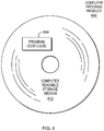
- FIG. 6 an example computer program product 600 is depicted that includes, for instance, one or more computer readable storage media 602 to store computer-readable program code means, logic and/or instructions 604 thereon to provide and facilitate one or more embodiments described herein.
- a computer-readable storage medium can be, as examples, electronic, magnetic, electromagnetic, optical, and/or semi-conductor-based. Examples include but are not limited to: random access memory, read-only memory, computer disks, flash memory, and optical storage media like compact disks (CDs) or digital versatile disks (DVDs). As specifically used herein, computer-readable storage media does not per se consist of transitory signals, such as radio waves or other propagating signals.
- Program code contained or stored in/on a computer readable storage medium can be obtained and executed by a computer system (computer, processing system, data processing system, etc. including a component thereof) and/or other device to cause the computer system, component thereof, and/or other device to behave/function in a particular manner.
- the program code can be transmitted using any appropriate medium, including (but not limited to) wireless, wireline, optical fiber, and/or radio-frequency.
- Program code for carrying out operations to perform, achieve, or facilitate aspects described herein may be written in one or more programming languages.
- the programming language(s) include object-oriented and/or procedural programming languages such as C, C++, C#, Java, etc.
- Program code may execute entirely or partially on the computer system, a remote computer system, or a combination of partially on the computer system and partially on a remote computer system.
- Program code can include program instructions obtained for execution by processor(s).
- Computer program instructions may be provided to processor(s) of, e.g., a computer system, to produce a machine, such that the program instructions, when executed by the processor(s), perform, achieve, or facilitate aspects described herein, such as actions, processes, or functions described in flowcharts and/or block diagrams described herein.
- each block, or combinations of blocks, of the flowchart illustrations and/or block diagrams depicted and described herein can be implemented, in some embodiments, by computer program instructions. Behaviors/functions specified or performed by one or more blocks may occur in a different order than depicted and/or described, or may occur simultaneous to, or partially/wholly concurrent with, one or more other blocks.
Landscapes
- Engineering & Computer Science (AREA)
- Robotics (AREA)
- Mechanical Engineering (AREA)
- Computer Vision & Pattern Recognition (AREA)
- Physics & Mathematics (AREA)
- General Physics & Mathematics (AREA)
- Theoretical Computer Science (AREA)
- Manipulator (AREA)
- Image Processing (AREA)
- Image Analysis (AREA)
- Length Measuring Devices By Optical Means (AREA)
Claims (13)
- Computerimplementiertes Verfahren, Folgendes umfassend:Erhalten, für jeden Zeitpunkt mehrerer Zeitpunkte eines ersten Abtastplans, einer jeweiligen Anzeige einer Lage eines Kamerasystems eines Roboters relativ zu einem Referenzkoordinatennetzrahmen, wobei die jeweilige Anzeige der Lage des Kamerasystems auf einem Vergleich mehrerer dreidimensionaler Bilder einer Szene einer Umgebung basiert, wobei das Erhalten mehrere Anzeigen von Lagen des Kamerasystems bereitstellt;Erhalten, für jeden Zeitpunkt mehrerer Zeitpunkte eines zweiten Abtastplans, einer jeweiligen Anzeige einer Lage des Roboters, wobei das Erhalten mehrere Anzeigen von Lagen des Roboters bereitstellt; undBestimmen, unter Verwendung der mehreren Anzeigen von Lagen des Kamerasystems und der mehreren Anzeigen von Lagen des Roboters, einer Anzeige des Referenzkoordinatennetzrahmens und einer Anzeige eines Referenzpunkts des Kamerasystems relativ zu der Lage des Roboters,wobeidas Verwenden der mehreren Anzeigen von Lagen des Kamerasystems und der mehreren Anzeigen von Lagen des Roboters ein Erstellen mehrerer Gleichungen umfasst, die die mehreren Lagen des Kamerasystems über den ersten Abtastplan hinweg mit den mehreren Lagen des Roboters über den zweiten Abtastplan hinweg in Beziehung setzen, wobei das Inbeziehungsetzen eine Funktion des Referenzkoordinatennetzrahmens und des Referenzpunkts des Kamerasystems relativ zu der Lage des Roboters ist; unddas Bestimmen ein Finden einer Lösung für die mehreren Gleichungen umfasst, um die Anzeige des Referenzkoordinatennetzrahmens und die Anzeige des Referenzpunkts des Kamerasystems zu bestimmen.
- Verfahren nach Anspruch 1, wobei das Erstellen der mehreren Gleichungen, für jede Anzeige einer Lage des Kamerasystems, der mehreren Anzeigen von Lagen des Kamerasystems, ein Identifizieren einer jeweiligen entsprechenden Lage des Roboters umfasst, wobei die jeweilige entsprechende Lage des Roboters auf einer oder mehreren Anzeigen von Lagen des Roboters der mehreren Anzeigen von Lagen des Roboters basiert.
- Verfahren nach Anspruch 2, wobei sich der erste Abtastplan und der zweite Abtastplan um einen Zeitversatz unterscheiden und eine identifizierte jeweilige entsprechende Lage des Roboters für eine Anzeige der Lage des Kamerasystems eine interpolierte Lage des Roboters umfasst, die basierend darauf interpoliert wird, dass die eine oder die mehreren Anzeigen von Lagen des Roboters eine Lage des Roboters zu einem Zeitpunkt sind, der sich von einem Zeitpunkt des Erhaltens einer der mehreren Anzeigen von Lagen des Roboters um eine Zeitmenge unterscheidet, die gleich dem Zeitversatz ist.
- Verfahren nach Anspruch 3, wobei der Zeitversatz anfänglich unbekannt ist und wobei das Finden der Lösung für die mehreren Gleichungen entweder ein Finden einer Lösung für den Zeitversatz mit dem Finden der Lösung für die mehreren Gleichungen, um die Anzeige des Referenzkoordinatennetzrahmens und die Anzeige des Referenzpunkts des Kamerasystems zu bestimmen, oder zuerst ein Finden einer Lösung für den Zeitversatz und ein Verwenden dieser Lösung für den Zeitversatz bei dem Finden der Lösung für die mehreren Gleichungen umfasst.
- Verfahren nach Anspruch 1, wobei die Lage des Roboters durch die Lage eines Befestigungsflansches des Roboters dargestellt wird; oder
wobei die Lage des Roboters durch Gelenkmessungen des Roboters dargestellt wird. - Verfahren nach Anspruch 1, wobei die erhaltenen mehreren Anzeigen von Lagen des Kamerasystems und die erhaltenen mehreren Anzeigen von Lagen des Roboters basierend darauf erhalten werden, dass der Roboter Bilder einer Szene einer Umgebung erhält, und wobei das Verfahren ferner ein Zusammenfügen von Bildern von wenigstens einem Teil der Szene der Umgebung unter Verwendung eines Bildregistrierungsverfahrens umfasst.
- Verfahren nach Anspruch 1, wobei der Vergleich ohne Kenntnis eines Abstands zwischen Merkmalen der Szene durchgeführt wird.
- Verfahren nach Anspruch 1, wobei die bestimmte Anzeige des Referenzpunkts des Kamerasystems als eine automatisierte Kalibrierung für den Referenzpunkt des Kamerasystems dient und wobei das Verfahren ferner ein Zusammenfügen von Bildern, die durch den Roboter erhalten wurden, von wenigstens einem Teil einer Szene einer Umgebung unter Verwendung gemessener Roboterpositionen und der bestimmten Anzeige des Referenzpunkts des Kamerasystems umfasst.
- Verfahren nach Anspruch 1, wobei das Erhalten der mehreren Anzeigen von Lagen des Kamerasystems und das Erhalten der mehreren Anzeigen von Lagen des Roboters mit einer Roboterbewegung und einer Abbildung eines ersten Scanbereichs einer Umgebung verbunden ist, in der der Roboter betrieben wird, und das Bestimmen die Anzeige des Referenzkoordinatennetzrahmens und die Anzeige des Referenzpunkts des Kamerasystems für den ersten Scanbereich bestimmt, und wobei das Verfahren ferner Folgendes umfasst:Wiederholen des Erhaltens der mehreren Anzeigen von Lagen des Kamerasystems und des Erhaltens der mehreren Anzeigen von Lagen des Roboters in Verbindung mit der Roboterbewegung und der Abbildung von wenigstens einem anderen Scanbereich der Umgebung; undWiederholen des Bestimmens, um eine Anzeige eines Referenzkoordinatennetzrahmens und eine Anzeige eines Referenzpunkts des Kamerasystems für den wenigstens einen anderen Scanbereich zu bestimmen.
- Verfahren nach Anspruch 1, wobei das Verfahren ferner Folgendes umfasst:Identifizieren einer Position eines Merkmals in einem Szenenraum einer Szene, die durch den Roboter abgebildet wird;Verwenden der bestimmten Anzeige des Referenzkoordinatennetzrahmens und einer Beziehung zwischen der bestimmten Anzeige des Referenzkoordinatennetzrahmens und der identifizierten Position des Merkmals in dem Szenenraum, um eine Position des Merkmals in einem Roboterraum zu identifizieren; undBereitstellen der identifizierten Position des Merkmals in dem Roboterraum, um die Positionierung des Roboters zu informieren.
- Computersystem, umfassend Mittel zum Vornehmen des Verfahrens nach Anspruch 1 oder 10.
- Computerprogrammprodukt, Folgendes umfassend:ein computerlesbares Speichermedium, das durch einen Prozessor gelesen werden kann und Anweisungen für eine Ausführung durch den Prozessor zum Durchführen eines Verfahrens speichert, Folgendes umfassend:Erhalten, für jeden Zeitpunkt mehrerer Zeitpunkte eines ersten Abtastplans, einer jeweiligen Anzeige einer Lage eines Kamerasystems eines Roboters relativ zu einem Referenzkoordinatennetzrahmen, wobei die jeweilige Anzeige der Lage des Kamerasystems auf einem Vergleich mehrerer dreidimensionaler Bilder einer Szene einer Umgebung basiert, wobei das Erhalten mehrere Anzeigen von Lagen des Kamerasystems bereitstellt;Erhalten, für jeden Zeitpunkt mehrerer Zeitpunkte eines zweiten Abtastplans, einer jeweiligen Anzeige einer Lage des Roboters, wobei das Erhalten mehrere Anzeigen von Lagen des Roboters bereitstellt; undBestimmen, unter Verwendung der mehreren Anzeigen von Lagen des Kamerasystems und der mehreren Anzeigen von Lagen des Roboters, einer Anzeige des Referenzkoordinatennetzrahmens und einer Anzeige eines Referenzpunkts des Kamerasystems relativ zu der Lage des Roboters,wobeidas Verwenden der mehreren Anzeigen von Lagen des Kamerasystems und der mehreren Anzeigen von Lagen des Roboters das Erstellen mehrerer Gleichungen umfasst, die die mehreren Lagen des Kamerasystems über den ersten Abtastplan hinweg mit den mehreren Lagen des Roboters über den zweiten Abtastplan hinweg in Beziehung setzen, wobei das Inbeziehungsetzen eine Funktion des Referenzkoordinatenrahmens und des Referenzpunkts des Kamerasystems relativ zu der Pose des Roboters ist, und wobei das Bestimmen das Finden einer Lösung für die mehreren Gleichungen umfasst, um die Anzeige des Referenzkoordinatenrahmens und die Anzeige des Referenzpunkts des Kamerasystems zu bestimmen.
- Computerprogrammprodukt nach Anspruch 12 oder Verfahren nach Anspruch 1, wobei die Szene Merkmale unbekannter Eigenschaften umfasst.
Applications Claiming Priority (2)
| Application Number | Priority Date | Filing Date | Title |
|---|---|---|---|
| US14/941,823 US10173324B2 (en) | 2015-11-16 | 2015-11-16 | Facilitating robot positioning |
| PCT/US2016/062059 WO2017087398A1 (en) | 2015-11-16 | 2016-11-15 | Facilitating robot positioning |
Publications (3)
| Publication Number | Publication Date |
|---|---|
| EP3377948A1 EP3377948A1 (de) | 2018-09-26 |
| EP3377948A4 EP3377948A4 (de) | 2019-06-19 |
| EP3377948B1 true EP3377948B1 (de) | 2021-01-06 |
Family
ID=58691170
Family Applications (1)
| Application Number | Title | Priority Date | Filing Date |
|---|---|---|---|
| EP16866952.1A Active EP3377948B1 (de) | 2015-11-16 | 2016-11-15 | Ermöglichung der positionierung eines roboters |
Country Status (4)
| Country | Link |
|---|---|
| US (1) | US10173324B2 (de) |
| EP (1) | EP3377948B1 (de) |
| CN (1) | CN109313417B (de) |
| WO (1) | WO2017087398A1 (de) |
Cited By (3)
| Publication number | Priority date | Publication date | Assignee | Title |
|---|---|---|---|---|
| WO2025132540A1 (de) | 2023-12-22 | 2025-06-26 | Carl Zeiss GOM Metrology GmbH | Verfahren und vorrichtung zum kalibrieren eines roboters, verfahren zum bestimmen der 3d-koordinaten eines messobjekts, verfahren zum bestimmen der position und orientierung eines messobjekts, roboter und computerprogramm |
| WO2025132505A1 (de) | 2023-12-22 | 2025-06-26 | Carl Zeiss GOM Metrology GmbH | Verfahren und vorrichtung zum kalibrieren eines roboters, verfahren zum bestimmen der 3d-koordinaten eines messobjekts, verfahren zum bestimmen der position und orientierung eines messobjekts, roboter und computerprogramm |
| WO2025132520A1 (de) | 2023-12-22 | 2025-06-26 | Carl Zeiss GOM Metrology GmbH | Verfahren und vorrichtung zum kalibrieren eines roboters, verfahren zum bestimmen der 3d-koordinaten eines messobjekts, verfahren zum bestimmen der position und orientierung eines messobjekts, roboter und computerprogramm |
Families Citing this family (43)
| Publication number | Priority date | Publication date | Assignee | Title |
|---|---|---|---|---|
| JP2016221645A (ja) * | 2015-06-02 | 2016-12-28 | セイコーエプソン株式会社 | ロボット、ロボット制御装置およびロボットシステム |
| DE102016212695B4 (de) * | 2016-05-31 | 2019-02-21 | Siemens Aktiengesellschaft | Industrieroboter |
| JP6420296B2 (ja) * | 2016-12-01 | 2018-11-07 | ファナック株式会社 | ロボットの干渉領域を自動で設定するロボット制御装置 |
| US10435179B2 (en) * | 2017-04-18 | 2019-10-08 | Electroimpact, Inc. | Camera assisted robotic system for locating the end of a fastener extending through an aircraft part during manufacture thereof |
| JP7003454B2 (ja) * | 2017-06-15 | 2022-01-20 | オムロン株式会社 | 制御装置、位置制御システム、位置制御方法、および、位置制御プログラム |
| EP3422501B1 (de) * | 2017-06-28 | 2021-04-28 | ABB Schweiz AG | Robot für unbemannten betrieb und wartung in einem mittel- oder hochspannungsgehäuse |
| TWI672207B (zh) * | 2017-11-03 | 2019-09-21 | 財團法人工業技術研究院 | 機械設備之定位系統及其方法 |
| EP3750028B1 (de) | 2018-02-09 | 2022-10-19 | Pupil Labs GmbH | Vorrichtungen, systeme und verfahren zur vorhersage von blickbezogenen parametern |
| EP3750029A1 (de) | 2018-02-09 | 2020-12-16 | Pupil Labs GmbH | Vorrichtungen, systeme und verfahren zur vorhersage von parametern im zusammen mit dem blick unter verwendung eines neuronalen netzes |
| US11393251B2 (en) | 2018-02-09 | 2022-07-19 | Pupil Labs Gmbh | Devices, systems and methods for predicting gaze-related parameters |
| JP6888580B2 (ja) * | 2018-04-05 | 2021-06-16 | オムロン株式会社 | 情報処理装置、情報処理方法、及びプログラム |
| WO2019234814A1 (ja) * | 2018-06-05 | 2019-12-12 | 株式会社日立製作所 | カメラ位置姿勢校正装置、カメラ位置姿勢校正方法並びにロボット |
| EP3818341A4 (de) * | 2018-07-06 | 2022-03-16 | Brain Corporation | Systeme, verfahren und vorrichtungen zum kalibrieren von auf einer vorrichtung montierten sensoren |
| CN112740274B (zh) * | 2018-09-15 | 2024-08-09 | 高通股份有限公司 | 在机器人设备上使用光流传感器进行vslam比例估计的系统和方法 |
| CN112005079B (zh) | 2019-01-03 | 2022-08-09 | 北京嘀嘀无限科技发展有限公司 | 用于更新高清地图的系统和方法 |
| JP7417356B2 (ja) | 2019-01-25 | 2024-01-18 | 株式会社ソニー・インタラクティブエンタテインメント | ロボット制御システム |
| JP7309371B2 (ja) * | 2019-01-25 | 2023-07-18 | 株式会社ソニー・インタラクティブエンタテインメント | ロボット制御システム |
| JP7190919B2 (ja) | 2019-01-25 | 2022-12-16 | 株式会社ソニー・インタラクティブエンタテインメント | 画像解析システム |
| EP3930964A1 (de) * | 2019-02-27 | 2022-01-05 | ABB Schweiz AG | Verfahren und system zur robotermontage |
| CN109900207A (zh) * | 2019-03-12 | 2019-06-18 | 精诚工科汽车系统有限公司 | 机器人视觉工具的工具中心点标定方法及系统 |
| US12036663B2 (en) | 2019-03-25 | 2024-07-16 | Abb Schweiz Ag | Method and control arrangement for determining a relation between a robot coordinate system and a movable apparatus coordinate system |
| US11579626B2 (en) * | 2019-05-30 | 2023-02-14 | Lg Electronics Inc. | Method of localization by synchronizing multi sensors and robot implementing same |
| US11676422B2 (en) | 2019-06-05 | 2023-06-13 | Pupil Labs Gmbh | Devices, systems and methods for predicting gaze-related parameters |
| EP3987380B1 (de) | 2019-06-18 | 2024-10-16 | Pupil Labs GmbH | Systeme und verfahren zur bestimmung eines oder mehrerer parameter des auges eines benutzers |
| CN110480631A (zh) * | 2019-07-19 | 2019-11-22 | 五邑大学 | 一种应用于搬运机器人的目标搬运方法及其搬运机器人 |
| CN110347162A (zh) * | 2019-07-29 | 2019-10-18 | 南京市晨枭软件技术有限公司 | 一种工业机器人路径自动修正的方法及系统 |
| CN111319041B (zh) * | 2020-01-17 | 2021-04-16 | 深圳市优必选科技股份有限公司 | 一种机器人位姿确定方法、装置、可读存储介质及机器人 |
| EP4093578A4 (de) * | 2020-01-22 | 2023-10-18 | Abb Schweiz Ag | System und verfahren zum betreiben eines roboters, elektronisches gerät und computerlesbares medium |
| WO2021147026A1 (en) * | 2020-01-22 | 2021-07-29 | Abb Schweiz Ag | Method and electronic device, system and computer readable medium for time calibration |
| EP3973346B1 (de) | 2020-02-19 | 2024-12-25 | Pupil Labs GmbH | Augenverfolgungmodul und am kopf tragbare vorrichtung |
| US11232595B1 (en) | 2020-09-08 | 2022-01-25 | Weta Digital Limited | Three-dimensional assembly for motion capture calibration |
| US11282233B1 (en) * | 2020-09-08 | 2022-03-22 | Weta Digital Limited | Motion capture calibration |
| CN112329530B (zh) * | 2020-09-30 | 2023-03-21 | 北京航空航天大学 | 支架的安装状态检测方法、设备及系统 |
| CN112269386B (zh) * | 2020-10-28 | 2024-04-02 | 深圳拓邦股份有限公司 | 对称环境重定位方法、装置及机器人 |
| US12115685B2 (en) * | 2021-07-12 | 2024-10-15 | Midea Group Co., Ltd. | Fast and robust initialization method for feature-based monocular visual SLAM using inertial odometry assistance |
| CN113676279B (zh) * | 2021-08-23 | 2024-09-06 | 追觅创新科技(苏州)有限公司 | 时间同步方法、设备、存储介质及系统 |
| CN114700962B (zh) * | 2022-03-22 | 2023-09-29 | 南京航空航天大学 | 一种用于长臂展高空作业复合机器人的末端位姿精度补偿方法 |
| JP2023153555A (ja) * | 2022-04-05 | 2023-10-18 | 株式会社不二越 | 撮像装置の位置推定方法 |
| US11717974B1 (en) * | 2022-06-10 | 2023-08-08 | Sanctuary Cognitive Systems Corporation | Haptic photogrammetry in robots and methods for operating the same |
| EP4293192B1 (de) | 2022-06-17 | 2025-10-15 | Sandvik Mining and Construction Oy | Bereitstellung von steuerinformationen |
| CN116495464A (zh) * | 2023-04-25 | 2023-07-28 | 姜贤富 | 可穿刺软体的转移机构 |
| CN118927233A (zh) * | 2023-05-10 | 2024-11-12 | 株式会社达谊恒 | 终端装置 |
| WO2025165265A1 (en) * | 2024-01-29 | 2025-08-07 | Epiroc Rock Drills Aktiebolag | A mining machine and a system for insertion of an object into a drilled hole |
Family Cites Families (21)
| Publication number | Priority date | Publication date | Assignee | Title |
|---|---|---|---|---|
| US6044308A (en) * | 1997-06-13 | 2000-03-28 | Huissoon; Jan Paul | Method and device for robot tool frame calibration |
| DE10345743A1 (de) * | 2003-10-01 | 2005-05-04 | Kuka Roboter Gmbh | Verfahren und Vorrichtung zum Bestimmen von Position und Orientierung einer Bildempfangseinrichtung |
| US8437535B2 (en) * | 2006-09-19 | 2013-05-07 | Roboticvisiontech Llc | System and method of determining object pose |
| JP4508252B2 (ja) * | 2008-03-12 | 2010-07-21 | 株式会社デンソーウェーブ | ロボット教示装置 |
| DE102009041734B4 (de) * | 2009-09-16 | 2023-11-02 | Kuka Roboter Gmbh | Vermessung eines Manipulators |
| CN102612423B (zh) * | 2009-11-12 | 2014-09-03 | 株式会社安川电机 | 机器人及其控制装置 |
| US9393694B2 (en) * | 2010-05-14 | 2016-07-19 | Cognex Corporation | System and method for robust calibration between a machine vision system and a robot |
| EP2608938B1 (de) * | 2010-08-27 | 2014-07-02 | ABB Research LTD | Sichtgeführtes ausrichtungssystem und verfahren |
| US8165403B1 (en) * | 2010-11-19 | 2012-04-24 | Mitsubishi Electric Research Laboratories, Inc. | Method and system for determining poses of specular objects |
| US9124873B2 (en) * | 2010-12-08 | 2015-09-01 | Cognex Corporation | System and method for finding correspondence between cameras in a three-dimensional vision system |
| JP2013022705A (ja) * | 2011-07-25 | 2013-02-04 | Sony Corp | ロボット装置及びロボット装置の制御方法、コンピューター・プログラム、並びにロボット・システム |
| US8958911B2 (en) * | 2012-02-29 | 2015-02-17 | Irobot Corporation | Mobile robot |
| US9420265B2 (en) * | 2012-06-29 | 2016-08-16 | Mitsubishi Electric Research Laboratories, Inc. | Tracking poses of 3D camera using points and planes |
| US8954195B2 (en) * | 2012-11-09 | 2015-02-10 | Harris Corporation | Hybrid gesture control haptic system |
| US9132551B2 (en) * | 2012-11-30 | 2015-09-15 | Abb Technology Ag | Teleoperated industrial robots |
| CN103085084B (zh) * | 2013-01-29 | 2015-03-04 | 山东电力集团公司电力科学研究院 | 一种用于高压带电作业机器人的视觉系统及工作方法 |
| US9457470B2 (en) * | 2013-04-05 | 2016-10-04 | Abb Technology Ltd | Robot system and method for calibration |
| JP5786896B2 (ja) * | 2013-06-07 | 2015-09-30 | 株式会社安川電機 | ワーク検出装置、ロボットシステム、被加工物の製造方法及びワーク検出方法 |
| US10306206B2 (en) | 2013-07-23 | 2019-05-28 | The Regents Of The University Of California | 3-D motion estimation and online temporal calibration for camera-IMU systems |
| CN104835173B (zh) * | 2015-05-21 | 2018-04-24 | 东南大学 | 一种基于机器视觉的定位方法 |
| CN105014667B (zh) * | 2015-08-06 | 2017-03-08 | 浙江大学 | 一种基于像素空间优化的相机与机器人相对位姿标定方法 |
-
2015
- 2015-11-16 US US14/941,823 patent/US10173324B2/en active Active
-
2016
- 2016-11-15 CN CN201680079119.XA patent/CN109313417B/zh active Active
- 2016-11-15 WO PCT/US2016/062059 patent/WO2017087398A1/en not_active Ceased
- 2016-11-15 EP EP16866952.1A patent/EP3377948B1/de active Active
Non-Patent Citations (1)
| Title |
|---|
| None * |
Cited By (3)
| Publication number | Priority date | Publication date | Assignee | Title |
|---|---|---|---|---|
| WO2025132540A1 (de) | 2023-12-22 | 2025-06-26 | Carl Zeiss GOM Metrology GmbH | Verfahren und vorrichtung zum kalibrieren eines roboters, verfahren zum bestimmen der 3d-koordinaten eines messobjekts, verfahren zum bestimmen der position und orientierung eines messobjekts, roboter und computerprogramm |
| WO2025132505A1 (de) | 2023-12-22 | 2025-06-26 | Carl Zeiss GOM Metrology GmbH | Verfahren und vorrichtung zum kalibrieren eines roboters, verfahren zum bestimmen der 3d-koordinaten eines messobjekts, verfahren zum bestimmen der position und orientierung eines messobjekts, roboter und computerprogramm |
| WO2025132520A1 (de) | 2023-12-22 | 2025-06-26 | Carl Zeiss GOM Metrology GmbH | Verfahren und vorrichtung zum kalibrieren eines roboters, verfahren zum bestimmen der 3d-koordinaten eines messobjekts, verfahren zum bestimmen der position und orientierung eines messobjekts, roboter und computerprogramm |
Also Published As
| Publication number | Publication date |
|---|---|
| CN109313417A (zh) | 2019-02-05 |
| US20170136626A1 (en) | 2017-05-18 |
| WO2017087398A1 (en) | 2017-05-26 |
| US10173324B2 (en) | 2019-01-08 |
| EP3377948A4 (de) | 2019-06-19 |
| EP3377948A1 (de) | 2018-09-26 |
| CN109313417B (zh) | 2021-09-24 |
Similar Documents
| Publication | Publication Date | Title |
|---|---|---|
| EP3377948B1 (de) | Ermöglichung der positionierung eines roboters | |
| US10046459B2 (en) | Three-dimensional visual servoing for robot positioning | |
| US10378353B2 (en) | Robot automated mining | |
| US11396100B2 (en) | Robot calibration for AR and digital twin | |
| EP3377722B1 (de) | Automatisches scannen und darstellen einer umgebung mit kollisionsvermeidung | |
| Melchiorre et al. | Collison avoidance using point cloud data fusion from multiple depth sensors: a practical approach | |
| JP2018169403A (ja) | 案内された組立環境におけるマシンビジョン座標空間を結合するためのシステム及び方法 | |
| US11090810B2 (en) | Robot system | |
| Settimi et al. | Augmented-reality-assisted timber drilling with smart retrofitted tools | |
| CN110856932B (zh) | 干涉回避装置以及机器人系统 | |
| US10349035B2 (en) | Automatically scanning and representing an environment having a plurality of features | |
| CN102785249A (zh) | 机械手控制系统,机械手系统以及程序 | |
| KR20140008262A (ko) | 로봇 시스템, 로봇, 로봇 제어 장치, 로봇 제어 방법 및 로봇 제어 프로그램 | |
| JP7366264B2 (ja) | ロボット教示方法及びロボット作業方法 | |
| Burrell et al. | Towards a cooperative robotic system for autonomous pipe cutting in nuclear decommissioning | |
| EP4382261A1 (de) | Robotersteuerungsvorrichtung, robotersteuerungssystem und robotersteuerungsverfahren | |
| Niu et al. | Eye-in-hand manipulation for remote handling: Experimental setup | |
| JP2012022600A (ja) | マスク画像作成システム | |
| US20230033821A1 (en) | Tool position determination in a robotic appendage | |
| JP7660658B2 (ja) | 自己位置推定システム及び自己位置推定方法 | |
| CN120152825A (zh) | 仿真系统和仿真方法 | |
| JP2021091070A (ja) | ロボット制御装置 | |
| Andersen et al. | Human assisted computer vision on industrial mobile robots |
Legal Events
| Date | Code | Title | Description |
|---|---|---|---|
| STAA | Information on the status of an ep patent application or granted ep patent |
Free format text: STATUS: THE INTERNATIONAL PUBLICATION HAS BEEN MADE |
|
| PUAI | Public reference made under article 153(3) epc to a published international application that has entered the european phase |
Free format text: ORIGINAL CODE: 0009012 |
|
| STAA | Information on the status of an ep patent application or granted ep patent |
Free format text: STATUS: REQUEST FOR EXAMINATION WAS MADE |
|
| 17P | Request for examination filed |
Effective date: 20180618 |
|
| AK | Designated contracting states |
Kind code of ref document: A1 Designated state(s): AL AT BE BG CH CY CZ DE DK EE ES FI FR GB GR HR HU IE IS IT LI LT LU LV MC MK MT NL NO PL PT RO RS SE SI SK SM TR |
|
| AX | Request for extension of the european patent |
Extension state: BA ME |
|
| DAV | Request for validation of the european patent (deleted) | ||
| DAX | Request for extension of the european patent (deleted) | ||
| RAP1 | Party data changed (applicant data changed or rights of an application transferred) |
Owner name: ABB SCHWEIZ AG |
|
| A4 | Supplementary search report drawn up and despatched |
Effective date: 20190521 |
|
| RIC1 | Information provided on ipc code assigned before grant |
Ipc: G06T 7/73 20170101AFI20190515BHEP |
|
| STAA | Information on the status of an ep patent application or granted ep patent |
Free format text: STATUS: EXAMINATION IS IN PROGRESS |
|
| 17Q | First examination report despatched |
Effective date: 20200416 |
|
| REG | Reference to a national code |
Ref country code: DE Ref legal event code: R079 Ref document number: 602016051212 Country of ref document: DE Free format text: PREVIOUS MAIN CLASS: G05B0015000000 Ipc: G06T0007730000 |
|
| RIC1 | Information provided on ipc code assigned before grant |
Ipc: B25J 9/16 20060101ALI20200917BHEP Ipc: G06T 7/73 20170101AFI20200917BHEP |
|
| GRAP | Despatch of communication of intention to grant a patent |
Free format text: ORIGINAL CODE: EPIDOSNIGR1 |
|
| STAA | Information on the status of an ep patent application or granted ep patent |
Free format text: STATUS: GRANT OF PATENT IS INTENDED |
|
| GRAS | Grant fee paid |
Free format text: ORIGINAL CODE: EPIDOSNIGR3 |
|
| INTG | Intention to grant announced |
Effective date: 20201105 |
|
| RIN1 | Information on inventor provided before grant (corrected) |
Inventor name: WANG, JIANJUN Inventor name: MORATO, CARLOS, W. Inventor name: MARTINEZ, CARLOS Inventor name: BOCA, REMUS Inventor name: ZHANG, BIAO |
|
| GRAA | (expected) grant |
Free format text: ORIGINAL CODE: 0009210 |
|
| STAA | Information on the status of an ep patent application or granted ep patent |
Free format text: STATUS: THE PATENT HAS BEEN GRANTED |
|
| AK | Designated contracting states |
Kind code of ref document: B1 Designated state(s): AL AT BE BG CH CY CZ DE DK EE ES FI FR GB GR HR HU IE IS IT LI LT LU LV MC MK MT NL NO PL PT RO RS SE SI SK SM TR |
|
| REG | Reference to a national code |
Ref country code: GB Ref legal event code: FG4D |
|
| REG | Reference to a national code |
Ref country code: AT Ref legal event code: REF Ref document number: 1353170 Country of ref document: AT Kind code of ref document: T Effective date: 20210115 Ref country code: CH Ref legal event code: EP |
|
| REG | Reference to a national code |
Ref country code: DE Ref legal event code: R096 Ref document number: 602016051212 Country of ref document: DE |
|
| REG | Reference to a national code |
Ref country code: IE Ref legal event code: FG4D |
|
| RAP4 | Party data changed (patent owner data changed or rights of a patent transferred) |
Owner name: ABB SCHWEIZ AG |
|
| REG | Reference to a national code |
Ref country code: NL Ref legal event code: MP Effective date: 20210106 |
|
| REG | Reference to a national code |
Ref country code: AT Ref legal event code: MK05 Ref document number: 1353170 Country of ref document: AT Kind code of ref document: T Effective date: 20210106 |
|
| REG | Reference to a national code |
Ref country code: LT Ref legal event code: MG9D |
|
| PG25 | Lapsed in a contracting state [announced via postgrant information from national office to epo] |
Ref country code: HR Free format text: LAPSE BECAUSE OF FAILURE TO SUBMIT A TRANSLATION OF THE DESCRIPTION OR TO PAY THE FEE WITHIN THE PRESCRIBED TIME-LIMIT Effective date: 20210106 Ref country code: GR Free format text: LAPSE BECAUSE OF FAILURE TO SUBMIT A TRANSLATION OF THE DESCRIPTION OR TO PAY THE FEE WITHIN THE PRESCRIBED TIME-LIMIT Effective date: 20210407 Ref country code: FI Free format text: LAPSE BECAUSE OF FAILURE TO SUBMIT A TRANSLATION OF THE DESCRIPTION OR TO PAY THE FEE WITHIN THE PRESCRIBED TIME-LIMIT Effective date: 20210106 Ref country code: PT Free format text: LAPSE BECAUSE OF FAILURE TO SUBMIT A TRANSLATION OF THE DESCRIPTION OR TO PAY THE FEE WITHIN THE PRESCRIBED TIME-LIMIT Effective date: 20210506 Ref country code: NO Free format text: LAPSE BECAUSE OF FAILURE TO SUBMIT A TRANSLATION OF THE DESCRIPTION OR TO PAY THE FEE WITHIN THE PRESCRIBED TIME-LIMIT Effective date: 20210406 Ref country code: BG Free format text: LAPSE BECAUSE OF FAILURE TO SUBMIT A TRANSLATION OF THE DESCRIPTION OR TO PAY THE FEE WITHIN THE PRESCRIBED TIME-LIMIT Effective date: 20210406 Ref country code: LT Free format text: LAPSE BECAUSE OF FAILURE TO SUBMIT A TRANSLATION OF THE DESCRIPTION OR TO PAY THE FEE WITHIN THE PRESCRIBED TIME-LIMIT Effective date: 20210106 |
|
| PG25 | Lapsed in a contracting state [announced via postgrant information from national office to epo] |
Ref country code: SE Free format text: LAPSE BECAUSE OF FAILURE TO SUBMIT A TRANSLATION OF THE DESCRIPTION OR TO PAY THE FEE WITHIN THE PRESCRIBED TIME-LIMIT Effective date: 20210106 Ref country code: RS Free format text: LAPSE BECAUSE OF FAILURE TO SUBMIT A TRANSLATION OF THE DESCRIPTION OR TO PAY THE FEE WITHIN THE PRESCRIBED TIME-LIMIT Effective date: 20210106 Ref country code: LV Free format text: LAPSE BECAUSE OF FAILURE TO SUBMIT A TRANSLATION OF THE DESCRIPTION OR TO PAY THE FEE WITHIN THE PRESCRIBED TIME-LIMIT Effective date: 20210106 Ref country code: PL Free format text: LAPSE BECAUSE OF FAILURE TO SUBMIT A TRANSLATION OF THE DESCRIPTION OR TO PAY THE FEE WITHIN THE PRESCRIBED TIME-LIMIT Effective date: 20210106 Ref country code: AT Free format text: LAPSE BECAUSE OF FAILURE TO SUBMIT A TRANSLATION OF THE DESCRIPTION OR TO PAY THE FEE WITHIN THE PRESCRIBED TIME-LIMIT Effective date: 20210106 |
|
| PG25 | Lapsed in a contracting state [announced via postgrant information from national office to epo] |
Ref country code: IS Free format text: LAPSE BECAUSE OF FAILURE TO SUBMIT A TRANSLATION OF THE DESCRIPTION OR TO PAY THE FEE WITHIN THE PRESCRIBED TIME-LIMIT Effective date: 20210506 |
|
| REG | Reference to a national code |
Ref country code: DE Ref legal event code: R097 Ref document number: 602016051212 Country of ref document: DE |
|
| PG25 | Lapsed in a contracting state [announced via postgrant information from national office to epo] |
Ref country code: SM Free format text: LAPSE BECAUSE OF FAILURE TO SUBMIT A TRANSLATION OF THE DESCRIPTION OR TO PAY THE FEE WITHIN THE PRESCRIBED TIME-LIMIT Effective date: 20210106 Ref country code: CZ Free format text: LAPSE BECAUSE OF FAILURE TO SUBMIT A TRANSLATION OF THE DESCRIPTION OR TO PAY THE FEE WITHIN THE PRESCRIBED TIME-LIMIT Effective date: 20210106 Ref country code: EE Free format text: LAPSE BECAUSE OF FAILURE TO SUBMIT A TRANSLATION OF THE DESCRIPTION OR TO PAY THE FEE WITHIN THE PRESCRIBED TIME-LIMIT Effective date: 20210106 |
|
| PLBE | No opposition filed within time limit |
Free format text: ORIGINAL CODE: 0009261 |
|
| STAA | Information on the status of an ep patent application or granted ep patent |
Free format text: STATUS: NO OPPOSITION FILED WITHIN TIME LIMIT |
|
| PG25 | Lapsed in a contracting state [announced via postgrant information from national office to epo] |
Ref country code: DK Free format text: LAPSE BECAUSE OF FAILURE TO SUBMIT A TRANSLATION OF THE DESCRIPTION OR TO PAY THE FEE WITHIN THE PRESCRIBED TIME-LIMIT Effective date: 20210106 Ref country code: RO Free format text: LAPSE BECAUSE OF FAILURE TO SUBMIT A TRANSLATION OF THE DESCRIPTION OR TO PAY THE FEE WITHIN THE PRESCRIBED TIME-LIMIT Effective date: 20210106 Ref country code: SK Free format text: LAPSE BECAUSE OF FAILURE TO SUBMIT A TRANSLATION OF THE DESCRIPTION OR TO PAY THE FEE WITHIN THE PRESCRIBED TIME-LIMIT Effective date: 20210106 |
|
| 26N | No opposition filed |
Effective date: 20211007 |
|
| PG25 | Lapsed in a contracting state [announced via postgrant information from national office to epo] |
Ref country code: ES Free format text: LAPSE BECAUSE OF FAILURE TO SUBMIT A TRANSLATION OF THE DESCRIPTION OR TO PAY THE FEE WITHIN THE PRESCRIBED TIME-LIMIT Effective date: 20210106 Ref country code: AL Free format text: LAPSE BECAUSE OF FAILURE TO SUBMIT A TRANSLATION OF THE DESCRIPTION OR TO PAY THE FEE WITHIN THE PRESCRIBED TIME-LIMIT Effective date: 20210106 |
|
| PG25 | Lapsed in a contracting state [announced via postgrant information from national office to epo] |
Ref country code: SI Free format text: LAPSE BECAUSE OF FAILURE TO SUBMIT A TRANSLATION OF THE DESCRIPTION OR TO PAY THE FEE WITHIN THE PRESCRIBED TIME-LIMIT Effective date: 20210106 |
|
| PG25 | Lapsed in a contracting state [announced via postgrant information from national office to epo] |
Ref country code: IT Free format text: LAPSE BECAUSE OF FAILURE TO SUBMIT A TRANSLATION OF THE DESCRIPTION OR TO PAY THE FEE WITHIN THE PRESCRIBED TIME-LIMIT Effective date: 20210106 |
|
| PG25 | Lapsed in a contracting state [announced via postgrant information from national office to epo] |
Ref country code: IS Free format text: LAPSE BECAUSE OF FAILURE TO SUBMIT A TRANSLATION OF THE DESCRIPTION OR TO PAY THE FEE WITHIN THE PRESCRIBED TIME-LIMIT Effective date: 20210506 |
|
| PG25 | Lapsed in a contracting state [announced via postgrant information from national office to epo] |
Ref country code: MC Free format text: LAPSE BECAUSE OF FAILURE TO SUBMIT A TRANSLATION OF THE DESCRIPTION OR TO PAY THE FEE WITHIN THE PRESCRIBED TIME-LIMIT Effective date: 20210106 |
|
| REG | Reference to a national code |
Ref country code: CH Ref legal event code: PL |
|
| GBPC | Gb: european patent ceased through non-payment of renewal fee |
Effective date: 20211115 |
|
| PG25 | Lapsed in a contracting state [announced via postgrant information from national office to epo] |
Ref country code: LU Free format text: LAPSE BECAUSE OF NON-PAYMENT OF DUE FEES Effective date: 20211115 Ref country code: BE Free format text: LAPSE BECAUSE OF NON-PAYMENT OF DUE FEES Effective date: 20211130 |
|
| REG | Reference to a national code |
Ref country code: BE Ref legal event code: MM Effective date: 20211130 |
|
| PG25 | Lapsed in a contracting state [announced via postgrant information from national office to epo] |
Ref country code: IE Free format text: LAPSE BECAUSE OF NON-PAYMENT OF DUE FEES Effective date: 20211115 Ref country code: GB Free format text: LAPSE BECAUSE OF NON-PAYMENT OF DUE FEES Effective date: 20211115 |
|
| PG25 | Lapsed in a contracting state [announced via postgrant information from national office to epo] |
Ref country code: FR Free format text: LAPSE BECAUSE OF NON-PAYMENT OF DUE FEES Effective date: 20211130 |
|
| PG25 | Lapsed in a contracting state [announced via postgrant information from national office to epo] |
Ref country code: HU Free format text: LAPSE BECAUSE OF FAILURE TO SUBMIT A TRANSLATION OF THE DESCRIPTION OR TO PAY THE FEE WITHIN THE PRESCRIBED TIME-LIMIT; INVALID AB INITIO Effective date: 20161115 |
|
| PG25 | Lapsed in a contracting state [announced via postgrant information from national office to epo] |
Ref country code: NL Free format text: LAPSE BECAUSE OF NON-PAYMENT OF DUE FEES Effective date: 20210206 Ref country code: CY Free format text: LAPSE BECAUSE OF FAILURE TO SUBMIT A TRANSLATION OF THE DESCRIPTION OR TO PAY THE FEE WITHIN THE PRESCRIBED TIME-LIMIT Effective date: 20210106 |
|
| PG25 | Lapsed in a contracting state [announced via postgrant information from national office to epo] |
Ref country code: LI Free format text: LAPSE BECAUSE OF NON-PAYMENT OF DUE FEES Effective date: 20220701 Ref country code: CH Free format text: LAPSE BECAUSE OF NON-PAYMENT OF DUE FEES Effective date: 20220701 |
|
| PG25 | Lapsed in a contracting state [announced via postgrant information from national office to epo] |
Ref country code: MK Free format text: LAPSE BECAUSE OF FAILURE TO SUBMIT A TRANSLATION OF THE DESCRIPTION OR TO PAY THE FEE WITHIN THE PRESCRIBED TIME-LIMIT Effective date: 20210106 |
|
| PG25 | Lapsed in a contracting state [announced via postgrant information from national office to epo] |
Ref country code: MT Free format text: LAPSE BECAUSE OF FAILURE TO SUBMIT A TRANSLATION OF THE DESCRIPTION OR TO PAY THE FEE WITHIN THE PRESCRIBED TIME-LIMIT Effective date: 20210106 |
|
| PG25 | Lapsed in a contracting state [announced via postgrant information from national office to epo] |
Ref country code: TR Free format text: LAPSE BECAUSE OF FAILURE TO SUBMIT A TRANSLATION OF THE DESCRIPTION OR TO PAY THE FEE WITHIN THE PRESCRIBED TIME-LIMIT Effective date: 20210106 |
|
| PGFP | Annual fee paid to national office [announced via postgrant information from national office to epo] |
Ref country code: DE Payment date: 20251119 Year of fee payment: 10 |