EP3377973B1 - Amélioration dans et autour des liaisons de communication - Google Patents
Amélioration dans et autour des liaisons de communication Download PDFInfo
- Publication number
- EP3377973B1 EP3377973B1 EP16801014.8A EP16801014A EP3377973B1 EP 3377973 B1 EP3377973 B1 EP 3377973B1 EP 16801014 A EP16801014 A EP 16801014A EP 3377973 B1 EP3377973 B1 EP 3377973B1
- Authority
- EP
- European Patent Office
- Prior art keywords
- crypto
- failure
- messages
- microprocessor
- configurable logic
- Prior art date
- Legal status (The legal status is an assumption and is not a legal conclusion. Google has not performed a legal analysis and makes no representation as to the accuracy of the status listed.)
- Active
Links
Images


Classifications
-
- H—ELECTRICITY
- H04—ELECTRIC COMMUNICATION TECHNIQUE
- H04L—TRANSMISSION OF DIGITAL INFORMATION, e.g. TELEGRAPHIC COMMUNICATION
- H04L1/00—Arrangements for detecting or preventing errors in the information received
- H04L1/08—Arrangements for detecting or preventing errors in the information received by repeating transmission, e.g. Verdan system
-
- G—PHYSICS
- G06—COMPUTING OR CALCULATING; COUNTING
- G06F—ELECTRIC DIGITAL DATA PROCESSING
- G06F11/00—Error detection; Error correction; Monitoring
- G06F11/07—Responding to the occurrence of a fault, e.g. fault tolerance
- G06F11/0703—Error or fault processing not based on redundancy, i.e. by taking additional measures to deal with the error or fault not making use of redundancy in operation, in hardware, or in data representation
- G06F11/0793—Remedial or corrective actions
-
- G—PHYSICS
- G06—COMPUTING OR CALCULATING; COUNTING
- G06F—ELECTRIC DIGITAL DATA PROCESSING
- G06F11/00—Error detection; Error correction; Monitoring
- G06F11/07—Responding to the occurrence of a fault, e.g. fault tolerance
- G06F11/0703—Error or fault processing not based on redundancy, i.e. by taking additional measures to deal with the error or fault not making use of redundancy in operation, in hardware, or in data representation
- G06F11/0706—Error or fault processing not based on redundancy, i.e. by taking additional measures to deal with the error or fault not making use of redundancy in operation, in hardware, or in data representation the processing taking place on a specific hardware platform or in a specific software environment
- G06F11/0736—Error or fault processing not based on redundancy, i.e. by taking additional measures to deal with the error or fault not making use of redundancy in operation, in hardware, or in data representation the processing taking place on a specific hardware platform or in a specific software environment in functional embedded systems, i.e. in a data processing system designed as a combination of hardware and software dedicated to performing a certain function
- G06F11/0739—Error or fault processing not based on redundancy, i.e. by taking additional measures to deal with the error or fault not making use of redundancy in operation, in hardware, or in data representation the processing taking place on a specific hardware platform or in a specific software environment in functional embedded systems, i.e. in a data processing system designed as a combination of hardware and software dedicated to performing a certain function in a data processing system embedded in automotive or aircraft systems
-
- H—ELECTRICITY
- H04—ELECTRIC COMMUNICATION TECHNIQUE
- H04L—TRANSMISSION OF DIGITAL INFORMATION, e.g. TELEGRAPHIC COMMUNICATION
- H04L41/00—Arrangements for maintenance, administration or management of data switching networks, e.g. of packet switching networks
- H04L41/06—Management of faults, events, alarms or notifications
- H04L41/0654—Management of faults, events, alarms or notifications using network fault recovery
- H04L41/0659—Management of faults, events, alarms or notifications using network fault recovery by isolating or reconfiguring faulty entities
- H04L41/0661—Management of faults, events, alarms or notifications using network fault recovery by isolating or reconfiguring faulty entities by reconfiguring faulty entities
-
- H—ELECTRICITY
- H04—ELECTRIC COMMUNICATION TECHNIQUE
- H04L—TRANSMISSION OF DIGITAL INFORMATION, e.g. TELEGRAPHIC COMMUNICATION
- H04L63/00—Network architectures or network communication protocols for network security
- H04L63/04—Network architectures or network communication protocols for network security for providing a confidential data exchange among entities communicating through data packet networks
- H04L63/0428—Network architectures or network communication protocols for network security for providing a confidential data exchange among entities communicating through data packet networks wherein the data content is protected, e.g. by encrypting or encapsulating the payload
-
- H—ELECTRICITY
- H04—ELECTRIC COMMUNICATION TECHNIQUE
- H04L—TRANSMISSION OF DIGITAL INFORMATION, e.g. TELEGRAPHIC COMMUNICATION
- H04L69/00—Network arrangements, protocols or services independent of the application payload and not provided for in the other groups of this subclass
- H04L69/40—Network arrangements, protocols or services independent of the application payload and not provided for in the other groups of this subclass for recovering from a failure of a protocol instance or entity, e.g. service redundancy protocols, protocol state redundancy or protocol service redirection
-
- G—PHYSICS
- G06—COMPUTING OR CALCULATING; COUNTING
- G06F—ELECTRIC DIGITAL DATA PROCESSING
- G06F21/00—Security arrangements for protecting computers, components thereof, programs or data against unauthorised activity
- G06F21/60—Protecting data
- G06F21/606—Protecting data by securing the transmission between two devices or processes
Definitions
- This invention relates to the field of communication links.
- the invention relates to a method and apparatus enabling mission-critical communication links, for example industrial control systems, to be protected from cyber-attacks.
- Mission-critical communication links are links which must be kept functioning, else significant consequences ensue (the consequences will of course depend on the purpose of the communication link). It is important that mission-critical communication links are not compromised by intrusion attacks, and it is conventional to encrypt links to prevent compromise. However, use of encryption equipment to protect the link from intrusion attacks creates the risk that the link will fail because of malfunction or failure of the encryption equipment.
- a supervising computer system controls a plurality of controlled devices, via programmable logic controllers (PLCs) or remote terminal unit (RTUs), with one PLC or RTU being associated with each controlled device.
- PLCs programmable logic controllers
- RTUs remote terminal unit
- An example of an industrial control system is a supervisory control and data acquisition (SCADA) system. SCADA systems are often used to control large-scale industrial systems, for example manufacturing equipment (e.g. a factory production line or heavy industrial process, e.g. a steel-works) or infrastructure equipment (e.g. railway signalling and control equipment, water treatment works or electricity generation and distribution networks, including e.g. nuclear reactors).
- manufacturing equipment e.g. a factory production line or heavy industrial process, e.g. a steel-works
- infrastructure equipment e.g. railway signalling and control equipment, water treatment works or electricity generation and distribution networks, including e.g. nuclear reactors.
- Encryption of the links between the supervising computer system and the controlled devices in industrial control systems has been proposed from time to time, but there has been a reluctance to add additional equipment, in-line between the supervising computer system and the controlled devices, that could reduce the reliability or compromise the integrity of the industrial control. Consequently, conventional industrial control systems have little or no protection against intrusion attacks. Clearly, a successful intrusion attack could have severe consequences, with an attacker potentially being able to control or disable the attacked industrial system.
- WO2015062812A1 discloses a safety-related system, in particular a railroad safety system, having a security gateway for transmitting data between a public network and a secure network.
- a security gateway supervisor is provided which bypasses the security gateway, monitors incoming and outgoing data of the security gateway without provoking reactions and has means for comparing the monitored data.
- JP2002319927A discloses a system wherein a power supply monitoring part inside a transmission line switching device monitors whether power is supplied from a power source to the transmission line switching device or not. When power is supplied, respective bypass line switching parts are switched to a direction, but when power supply is cut off, the respective bypass line switching parts are switched to a different direction. Thus, signals on a transmission line are connected through bypass lines to a terminal on the side of a present station and terminal on the side of an opposite station. Therefore, even when power supply to the transmission line switching device is cut off, the transmission line between the terminal is secured.
- US2010138534A1 discloses systems and methods for monitoring an access gateway.
- the systems and methods include monitors on appliances that generate and send requests to logon agents or login page services on access gateways. Based on the responses from the logon agents or login page services, the monitors determine whether the logon agents or login page services are available.
- CN101330382A discloses an auto bypass method used for a network cryptographic device, which provides an auto bypass method based on encryption tunnel intelligent selection.
- the method can automatically realize the bypass of the failure network cryptographic device, protect the normal work of opposite end devices, and ensure the stable operation of the whole system.
- the present invention provides apparatus directed towards improving the protection of communication links from intrusion attacks, whilst also maintaining reliability of the link.
- a first aspect of the invention provides a communication system having the features set out in claim 1 below.
- a second aspect of the invention provides a method having the features set out in claim 13 below.
- Embodiments are described herein in the context of approaches to improve the reliability of communication links protected from intrusion attacks.
- the invention provides use of encryption in the link but mitigates failures (including malfunctions) within encryption/decryption devices, maintaining the integrity of the link.
- the invention allows the link to be maintained under device failure conditions and, in some embodiments of the invention, provides a mechanism to raise an alarm to a controlling computer system
- the first aspect is directed to a communication system including a first crypto device, a second crypto device and a communication link connecting the first crypto device to the second crypto device, at least one of the crypto devices being arranged to send encrypted messages to the other of the crypto devices over the communication link, wherein the system includes a failure monitor arranged to monitor for a failure of at least one of the crypto devices, and, in the event of failure, to continue the sending of the messages but without encryption.
- the second aspect of the invention provides a method of operating a communication system, the method comprising sending encrypted messages over a communication link, monitoring for a system failure and, in the event of a system failure being detected, continuing to send the messages but sending them unencrypted.
- the communication system may be a control system, for example an industrial control system, for example a SCADA network.
- the communication system may further comprise one or more items of controlled equipment.
- the one or more items of controlled equipment may each be controlled by a PLC or RTU. There may be one PLC or RTU for each item of controlled equipment.
- the communication system may further comprise a controlling computer which controls the controlled equipment (directly or through the PLC or RTU).
- the failure monitor may be arranged to send a message to the controlling computer to report the failure.
- the failure monitor may be arranged to send messages to the controlling computer whilst no failure is detected and to stop sending the messages when a failure is detected.
- the controlling computer may monitor for the no-failure messages.
- the controlling computer may be arranged to report failure to a user.
- the first crypto device may comprise an encryption module for encrypting the messages.
- the first crypto device may comprise a decryption module for decrypting the encrypted messages.
- the second crypto device may comprise an encryption module for encrypting the messages.
- the second crypto device may comprise a decryption module for decrypting the encrypted messages.
- Messages both to and from each crypto device may be encrypted (i.e. there may be encryption in both directions between the devices).
- the encryption module and decryption module may share components within the crypto device.
- the monitoring may be for an internal fault in the crypto devices, for example failure of the encryption module or the decryption module.
- the monitoring may be for loss of power; for example, the failure monitor may be arranged to check that the power supply of the first and/or second crypto device is supplying power within a predetermined tolerance range.
- the crypto device may be comprised in a link end unit.
- the communication link may be an Ethernet link.
- At least one of the crypto devices may comprise an input port, through which incoming messages pass, and an output port, through which outgoing encrypted messages pass, and:
- the bypass switch arrangement may comprise a relay switch, and the relay switch may be arranged so that, when powered normally, it is in a powered state in which it connects the input port to the output port via the encryption and/or decryption module and, on loss of power, the relay switch defaults to an unpowered state in which it connects the input port to the output port whilst bypassing the encryption and/or decryption module.
- the bypass switch arrangement may comprise a transistor.
- At least one of the crypto devices may be arranged to send messages, confirming that it is functioning correctly, to the other crypto device.
- the other crypto device may be arranged to monitor for receipt of the messages confirming correct functioning, and to identify as a failure event a failure to receive said messages.
- the crypto device comprises a microprocessor.
- the crypto device comprises a configurable logic device, for example a field programmable gate array (FPGA).
- the microprocessor and the configurable logic device carry out encryption and/or decryption on encrypted messages.
- the microprocessor and the configurable logic device are arranged to generate signals to confirm that they are functioning correctly.
- the confirmation signals may be monitored by the failure monitor to detect failure.
- the microprocessor is arranged to generate a signal for the configurable logic device to confirm that the microprocessor is functioning correctly, to monitor the configurable logic device(for example, by monitoring a signal in the form of a changing register of the configurable logic device to confirm that the configurable logic device is functioning correctly, and to generate a signal for the failure monitor to confirm that the microprocessor and/or the configurable logic device is/are functioning correctly.
- the configurable logic device is arranged to generate a signal for the microprocessor to confirm that the configurable logic device is functioning correctly, to monitor the microprocessor to confirm that the microprocessor is functioning correctly, and to generate a signal for the failure monitor to confirm that the microprocessor and/or the configurable logic device is/are functioning correctly. Having the microprocessor confirm that the configurable logic device is functioning correctly (and vice versa ), rather than the microprocessor and the configurable logic device each checking themselves, guards against faults in the checking logic itself.
- the failure monitor may be configured to switch to sending the messages unencrypted if it does not receive the message confirming that the microprocessor and/or the configurable logic device is functioning correctly.
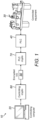
- a SCADA network 10 includes a controlling computer 20, an item of controlled equipment 30, and a PLC 40.
- the PLC 40 controls the equipment 30, and the PCL 40 is itself controlled by the controlling computer 20 (as is often the case, the controlling computer 20, in this example embodiment, controls many PLCs, each associated with a different item of equipment, but only one control link is shown in Fig. 1 , for ease of illustration).
- the network 10 also includes a controlling crypto device 60, associated with the controlling computer 20, and a PLC crypto device 70, associated with the PLC 40.
- the controlling crypto device 60 and the PLC crypto device 70 provide an encrypted link 50 between the controlling computer system 20 and the PLC 40.
- the controlling crypto device 60 and the PLC crypto device 70 each includes a mechanism to detect failure conditions (e.g. internal faults and/or loss of power) and to switch to unencrypted operation in the event that a failure condition is detected, to maintain the integrity of the link.
- failure conditions e.g. internal faults and/or loss of power
- a protocol is implemented in the controlling crypto device 60 and the PLC crypto 70, so that the controlling crypto 60 is aware of the failure and reverts back to a non-encrypted link.
- the controlling crypto device 60 then informs the controlling computer 20 of the failure and an alarm is raised. With this protocol, the PLC 40 itself is unaffected by the failure in the link.
- the controlling crypto device 60 provides an external plaintext interface 80, to which the controlling computer 20 provides messages for the PLC 40 and from which messages from the PLC are sent to the controlling computer 20, and an external cyphertext interface 90, from which the messages for the PLC 40 are sent along the encrypted link 50, and at which messages from the PLC 40 are received in encrypted form.
- the controlling crypto device 60 includes a crypto module 95.
- the crypto module includes an encryption module 100, for encrypting messages received on the plaintext interface 80 and transmitting the resulting encrypted message to the external cyphertext interface 90, and a decryption module 110, for decrypting encrypted messages received on the cyphertext interface 90 and transmitting the resulting decrypted message to the external plaintext interface 80.
- the controlling crypto device 60 also includes a failure monitor 120.
- the crypto module 95 transmits messages 105, confirming that the encryption module 100 and the decryption module 110 are functioning correctly. In the event of a failure of either module 100,110, the messages 105 are not transmitted.
- the controlling crypto device 60 detects the absence of messages 105 and activates a bypass 130, resulting in the messages received by the controlling crypto device 60 on its plaintext interface 80 being transmitted, bypassing the encryption module 100, to the PLC crypto device 70, without encryption; similarly, messages received on the cyphertext interface 90 are transmitted directly to the external plaintext interface 80, and thence to the controlling computer 20, without decryption.
- the controlling crypto device 60 includes a processor (CPU) 220, which provides the encryption and decryption functions of the controlling crypto device 60.
- the controlling crypto device 60 also includes a field-programmable gate array (FPGA) 210, which in this example provides an Ethernet interface (in some embodiments, encryption and decryption functions may be carried out by the FPGA, speeding up the system).
- the FPGA 210 is connected to an Ethernet physical-layer connection 240, which provides an internal plaintext interface 230 for the FPGA 210, and another Ethernet physical-layer connection 250, which provides an internal cyphertext interface 260 for the FPGA 210.
- the failure monitor 120 includes a relay control 200 and two bypass switches 130a, 130b (in alternative embodiments, separate relay controls may be provided for each bypass switch).
- This example system provides two basic failure protection mechanisms: protection against system power failure and protection against internal faults.
- the bypass function is implemented with relay switches 130a, 130b.
- the relay switches 130a, 130b When powered normally, the relay switches 130a, 130b connect the external plaintext interface 80 to the external cyphertext interface 90 via the internal plaintext interface 230, FPGA 210 and internal cyphertext interface 260.
- the relay switches 130a, 130b close to the normally closed position, in which the external plaintext interface 80 is connected directly to the external cyphertext interface 90, bypassing the internal plaintext interface 230, FPGA 210 and internal cyphertext interface 260.
- the FPGA 210 sends "CPU good” signals 280' to the relay control 200 and the CPU 220 sends "FPGA good” signals 280 to the relay control 200.
- the relay control 200 receives the "FPGA good” signals 280 and the "CPU good” signals 280', it maintains the relay switches 130a, 130b in their energised position (so that the path of messages between the external plaintext interface 80 and the external cyphertext interface 90 is via the internal plaintext interface 230, FPGA 210 and internal cyphertext interface 260, as described above).
- a "heart beat” signal 270 is generated by the FPGA 210 for the CPU 220 and another "heart beat” signal 270' is generated by the CPU 220 for the FPGA 210; thus, the "heart beat” signals enable the CPU 220 to monitor the FPGA 210 and the FPGA 210 to monitor the CPU 220.
- the relay control 200 does not receive both the "FPGA good” signal 280 and the "CPU good” signal 280', it will de-energise the relay switches 130a, 130b, so that they switch to their default, normally closed, positions, in which the external plaintext interface 80 is connected directly to the external cyphertext interface 90, bypassing the internal plaintext interface 230, FPGA 210 and internal cyphertext interface 260.
- the encryption and decryption provided by the FPGA 210 and CPU 220 are bypassed if the power, the FPGA 210 or the CPU 220 fails.
- the encryption and decryption are also bypassed if the PLC crypto 70 fails.
- the processor 220 boots and initialises all the hardware ready for normal operation.
- the processor 220 checks continuously that the power supply is within tolerance (step 310). If not, the network 10 transitions to the fail open state (i.e. bypassing FPGA 210 and CPU 220) by de-energising the relay switches 130a, 130b (step 370).
- the FPGA 210 monitors the heartbeat signal 270' from the processor 220 (step 320).
- the FPGA 210 transitions the link 10 to fail open (step 370) in the event that the heartbeat signal 270' goes out of tolerance.
- the processor 220 monitors the heartbeat signal 270 from the FPGA 210.
- the processor 220 transitions the link 10 to the fail open state (step 370) in the event that the heartbeat signal 270 goes out of tolerance.
- the heartbeat signals take the following form.
- the processor 220 reads the status of an internal register of the FPGA 210, the status changing periodically; if the status stops changing then the processor 220 will consider the FPGA 210 to be faulty and switch to "fail open".
- the FPGA 210 considers the processor 220 to have failed if the processor 220 does not access it within a pre-set timeout period.
- the processor 220 also has a self-checking "watchdog" function: it runs software which operates to access hardware within the processor 220 periodically. If that access does not occur within a pre-set period of time then the hardware on board the CPU is arranged to trigger a system reset, which also causes a "fail open" condition.
- the controlling crypto device 60 and the PLC crypto device 40 pass "keep alive" messages between each other via the encrypted link 50.
- Each crypto device 40, 60 checks for receipt of the messages (step 340), and, on receipt, responds with an "OK" message, again via the encrypted link 50. If either device 60, 40 detects the keep-alive message as being out of tolerance (in this example, when the crypto device 60, 40 does not receive an OK response within a certain time) then it transitions to fail open state (step 370) and stops transmitting and responding to keep-alive message. This also ensures that the other device 60, 40 transitions to the fail open state, as it no longer receives the "OK" responses.
- controlling crypto device 60 As long as the controlling crypto device 60 is in the normal encrypted link state it sends a regular "OK" message to the controlling computer 20 (step 350).
- An application running on the controlling computer 20 checks for receipt of the "OK” message. If the "OK” message goes out of tolerance then the monitoring application sets off a warning to an operator to indicate that the network 10 has transitioned to the fail open state (step 370).
- the controlling crypto 60 device only sends "OK” messages to the controlling computer 20. It only sends these messages if it has "OK” responses from the PLC crypto device, so the whole system is reflected in the "OK” messages from the controlling crypto device 60 to the controlling computer 20.
- the relays remain energised (step 360), which will keep Ethernet traffic passing correctly through the cryptographic devices 60, 70. If any of the monitored functions indicates an error then, as just described, the drive to the relays 130 is removed, connecting together the external plaintext interface 80 and the external cyphertext interface 90. That will effectively remove the controlling crypto 60 from the system, and the device will then cease to generate or respond to keep-alive messages, which will cause the PLC crypto 70 at the other end of the link 50 to also enter the "fail-open" state. The controlling crypto 60 will then stop sending the OK messages to the controlling PC 20 which will cause an alarm to be issued to the user.
- a single link 50 is provided for control signals between the controlling crypto 60 and the PLC crypto 70
- a separate link may be provided for traffic in each direction, so that in the event of a failure of encryption/decryption in one direction communications in that direction may be switched to plaintext, but communications in the other direction may continue encrypted.
- controlling crypto 60 is provided as a separate unit from the controlling computer 20, in other example embodiments the controlling crypto may be integrated with the controlling computer. Similarly, the controlled crypto may be integrated with the PLC or a RTU.
- failure monitors 120 are provided within the controlling and PLC cryptos 60, 70, in other example embodiments, the failure monitor can be provided separately from, but in communication with, the cryptos 60, 70.
Landscapes
- Engineering & Computer Science (AREA)
- Theoretical Computer Science (AREA)
- Computer Security & Cryptography (AREA)
- Signal Processing (AREA)
- Computer Networks & Wireless Communication (AREA)
- General Engineering & Computer Science (AREA)
- General Physics & Mathematics (AREA)
- Physics & Mathematics (AREA)
- Quality & Reliability (AREA)
- Computer Hardware Design (AREA)
- Computing Systems (AREA)
- Programmable Controllers (AREA)
- Maintenance And Management Of Digital Transmission (AREA)
- Small-Scale Networks (AREA)
Claims (13)
- Système de communication (10) incluant un premier dispositif cryptographique (60), un deuxième dispositif cryptographique (70) et un lien de communication (50) reliant le premier dispositif cryptographique au deuxième dispositif cryptographique, au moins un des dispositifs cryptographiques étant conçu pour envoyer des messages cryptés à l'autre dispositif cryptographique via le lien de communication,chaque dispositif cryptographique comprenant un microprocesseur (220) et un dispositif logique configurable (210), configuré pour effectuer un cryptage et/ou un décryptage sur les messages cryptés,le système incluant une surveillance de défaillance (120) conçue pour détecter une défaillance d'au moins un des dispositifs cryptographiques, et, en cas de défaillance, continuer à envoyer les messages, mais sans cryptage ;le microprocesseur étant conçu pour générer un signal à destination du dispositif logique configurable pour confirmer que le microprocesseur fonctionne correctement, surveiller le dispositif logique configurable afin de confirmer que celui-ci fonctionne correctement et générer un signal à destination de la surveillance de défaillance pour confirmer que le microprocesseur et/ou le dispositif logique fonctionne(nt) correctement,le dispositif logique configurable étant conçu pour générer un signal à destination du microprocesseur pour confirmer que le dispositif logique configurable fonctionne correctement, surveiller le microprocesseur pour confirmer que celui-ci fonctionne correctement et générer un signal à destination de la surveillance de défaillance pour confirmer que le microprocesseur et/ou le dispositif logique configurable fonctionne(nt) correctement.
- Système (10) suivant la revendication 1, le système étant un système de commande.
- Système (10) suivant la revendication 2, dans lequel la surveillance de défaillance (120) est conçue pour envoyer des messages à un ordinateur de commande (20) lorsqu'aucune défaillance n'est détectée et interrompre l'envoi de messages lorsqu'une défaillance est détectée ou la surveillance de défaillance est conçue pour envoyer, en cas de défaillance, un message à l'ordinateur de commande pour signaler la défaillance.
- Système (10) suivant une des revendications précédentes, dans lequel il y a cryptage de messages envoyés dans les deux directions entre les dispositifs cryptographiques (60, 70).
- Système (10) tel que revendiqué suivant une des revendications précédentes, dans lequel la surveillance porte sur un défaut interne dans les dispositifs cryptographiques (60, 70) ou une perte de puissance.
- Système (10) suivant une des revendications précédentes, dans lequel au moins un des dispositifs cryptographiques (60, 70) comprend un port d'entrée, à travers lequel passent les messages entrants et un port de sortie à travers lequel passent des messages cryptés sortants, et(i) un module crypté (100) relié pour recevoir du texte en clair depuis le port d'entrée et appliquer un algorithme de cryptage aux messages en clair, ainsi que pour fournir des messages de texte en clair résultants au port de sortie, ou(ii) un module de décryptage (110) relié pour recevoir des messages de texte crypté depuis le port d'entrée et appliquer un algorithme de décryptage aux messages en texte crypté, ainsi que fournir les messages de texte en clair résultants au port de sortie, ou(iii) les deux.
- Système (10) suivant la revendication 6, dans lequel, en cas de détection d'une défaillance, la surveillance de défaillance relie le port d'entrée au port de sortie de sorte que le module de cryptage et/ou de décryptage est court-circuité.
- Système (10) suivant la revendication 7, dans lequel la surveillance de défaillance (120) inclut un sectionneur de dérivation (130) et la surveillance de défaillance court-circuite le module de cryptage et/ou de décryptage en reliant le port d'entrée au port de sortie par commutation du sectionneur de dérivation.
- Système (10) suivant la revendication 8, dans lequel le sectionneur de dérivation comprend un commutateur à relais.
- Système (10) suivant une des revendications précédentes, dans lequel au moins un des dispositifs cryptographiques est conçu pour envoyer des messages à l'autre dispositif cryptographique confirmant qu'il fonctionne correctement.
- Système (10) suivant une des revendications précédentes, dans lequel la surveillance de défaillance (120) est incluse dans le premier dispositif cryptographique (60) ou le deuxième dispositif cryptographique (70).
- Système (10) suivant la revendication 11, dans lequel le premier dispositif cryptographique (60) et le deuxième dispositif cryptographique (70) incluent une surveillance de défaillance (120).
- Procédé consistant à faire fonctionner un système de communication (10), ledit procédé comportant les étapes suivantes qui consistent à :fournir un premier dispositif cryptographique (60), un deuxième dispositif cryptographique (70) et un lien de communication (50) reliant le premier dispositif cryptographique au deuxième dispositif cryptographique, chaque dispositif cryptographique comprenant un microprocesseur (220) et un dispositif logique configurable (210) configuré pour effectuer un cryptage et/ou un décryptage sur les messages cryptés,envoyer les messages cryptés via le lien de communication (50),surveiller une défaillance de système d'au moins un des dispositifs cryptographiques en :générant au niveau du microprocesseur un signal à destination du dispositif logique configurable afin de confirmer que le microprocesseur fonctionne correctement et surveiller le dispositif logique configurable pour confirmer que celui-ci fonctionne correctement et générer un signal pour confirmer que le microprocesseur et/ou le dispositif logique configurable fonctionne/nt correctement, etgénérer, au niveau du dispositif logique configurable, un message à destination du micro-processeur pour confirmer que le dispositif logique configurable fonctionne correctement, surveiller le microprocesseur pour confirmer que celui-ci fonctionne correctement et générer un signal pour confirmer que le microprocesseur et/ou le dispositif logique configurable fonctionne(nt) correctement, et en cas de détection d'une défaillance du système continuer à envoyer les messages, mais en les envoyant non cryptés.
Applications Claiming Priority (2)
| Application Number | Priority Date | Filing Date | Title |
|---|---|---|---|
| GB1520264.1A GB2544491B (en) | 2015-11-17 | 2015-11-17 | Improvements in and relating to communication links |
| PCT/GB2016/053576 WO2017085480A1 (fr) | 2015-11-17 | 2016-11-16 | Amélioration dans et autour des liaisons de communication |
Publications (3)
| Publication Number | Publication Date |
|---|---|
| EP3377973A1 EP3377973A1 (fr) | 2018-09-26 |
| EP3377973C0 EP3377973C0 (fr) | 2024-03-20 |
| EP3377973B1 true EP3377973B1 (fr) | 2024-03-20 |
Family
ID=55132921
Family Applications (1)
| Application Number | Title | Priority Date | Filing Date |
|---|---|---|---|
| EP16801014.8A Active EP3377973B1 (fr) | 2015-11-17 | 2016-11-16 | Amélioration dans et autour des liaisons de communication |
Country Status (4)
| Country | Link |
|---|---|
| US (2) | US10887054B2 (fr) |
| EP (1) | EP3377973B1 (fr) |
| GB (1) | GB2544491B (fr) |
| WO (1) | WO2017085480A1 (fr) |
Families Citing this family (4)
| Publication number | Priority date | Publication date | Assignee | Title |
|---|---|---|---|---|
| GB2544491B (en) * | 2015-11-17 | 2022-03-02 | Airbus Defence & Space Ltd | Improvements in and relating to communication links |
| CN114697320B (zh) * | 2020-12-31 | 2024-10-22 | 联想企业解决方案(新加坡)有限公司 | 边缘服务器和边缘服务器系统 |
| CN115834517B (zh) * | 2022-11-18 | 2026-04-14 | 北京东土军悦科技有限公司 | 故障隔离方法、装置、交换机及存储介质 |
| US12335167B2 (en) * | 2023-07-19 | 2025-06-17 | Hitachi, Ltd. | Security function execution device |
Family Cites Families (23)
| Publication number | Priority date | Publication date | Assignee | Title |
|---|---|---|---|---|
| US6990578B1 (en) * | 1999-10-29 | 2006-01-24 | International Business Machines Corp. | Method and apparatus for encrypting electronic messages composed using abbreviated address books |
| JP2002319927A (ja) * | 2001-04-24 | 2002-10-31 | Nec Miyagi Ltd | 伝送路切替装置及び伝送システム |
| US7185362B2 (en) * | 2001-08-20 | 2007-02-27 | Qualcomm, Incorporated | Method and apparatus for security in a data processing system |
| US7242766B1 (en) * | 2001-11-21 | 2007-07-10 | Silicon Image, Inc. | Method and system for encrypting and decrypting data using an external agent |
| US8145718B1 (en) * | 2005-10-21 | 2012-03-27 | Voltage Security, Inc. | Secure messaging system with personalization information |
| KR100715679B1 (ko) * | 2005-12-05 | 2007-05-09 | 한국전자통신연구원 | 인증 암호화를 통해 보안 전송을 가능하게 하는 gpon시스템 및 그 인증 암호화 방법 |
| JP4917318B2 (ja) * | 2006-01-31 | 2012-04-18 | 株式会社リコー | 通信装置、通信方法およびプログラム |
| CN101330382A (zh) * | 2008-05-30 | 2008-12-24 | 国网南京自动化研究院 | 一种基于加密隧道智能选择的自动旁路方法 |
| US8849988B2 (en) | 2008-11-25 | 2014-09-30 | Citrix Systems, Inc. | Systems and methods to monitor an access gateway |
| US8250362B2 (en) * | 2008-12-04 | 2012-08-21 | Broadcom Corporation | Home network encryption techniques |
| US9173100B2 (en) * | 2011-11-16 | 2015-10-27 | Autoconnect Holdings Llc | On board vehicle network security |
| CA2913007C (fr) * | 2013-05-23 | 2021-06-08 | Qubitekk, Inc. | Cle publique incorruptible utilisant une cryptographie quantique pour des communications securisees avec et sans fil |
| WO2015102694A2 (fr) * | 2013-09-30 | 2015-07-09 | Hughes Richard J | Authentification continue et sécurité multiniveau pour réseaux de communication utilisant la cryptographie quantique |
| WO2015048783A1 (fr) * | 2013-09-30 | 2015-04-02 | Nordholt, Jane, E. | Recouvrement de communications sécurisées quantiques pour des réseaux de communication par fibre optique |
| DE102013221955A1 (de) * | 2013-10-29 | 2015-05-21 | Siemens Aktiengesellschaft | Sicherheitsrelevantes System |
| US9547767B2 (en) * | 2013-11-13 | 2017-01-17 | Via Technologies, Inc. | Event-based apparatus and method for securing bios in a trusted computing system during execution |
| US9544395B2 (en) * | 2014-10-10 | 2017-01-10 | At&T Intellectual Property I, L.P. | Facilitating quality of service and security via functional classification of devices in networks |
| US9769661B2 (en) * | 2015-04-06 | 2017-09-19 | Qualcomm, Incorporated | Wireless network fast authentication / association using re-association object |
| US10341311B2 (en) * | 2015-07-20 | 2019-07-02 | Schweitzer Engineering Laboratories, Inc. | Communication device for implementing selective encryption in a software defined network |
| GB2544491B (en) * | 2015-11-17 | 2022-03-02 | Airbus Defence & Space Ltd | Improvements in and relating to communication links |
| US9891978B1 (en) * | 2015-12-03 | 2018-02-13 | Rockwell Collins, Inc. | Fault detection in a multi-core safety-critical avionics system |
| US10412064B2 (en) * | 2016-01-11 | 2019-09-10 | Centurylink Intellectual Property Llc | System and method for implementing secure communications for internet of things (IOT) devices |
| ES2885075T3 (es) * | 2016-12-15 | 2021-12-13 | Fmc Tech Inc | Bloque contador inteligente |
-
2015
- 2015-11-17 GB GB1520264.1A patent/GB2544491B/en active Active
-
2016
- 2016-11-16 WO PCT/GB2016/053576 patent/WO2017085480A1/fr not_active Ceased
- 2016-11-16 EP EP16801014.8A patent/EP3377973B1/fr active Active
- 2016-11-16 US US15/776,706 patent/US10887054B2/en active Active
-
2020
- 2020-10-27 US US17/081,631 patent/US11374689B2/en active Active
Also Published As
| Publication number | Publication date |
|---|---|
| EP3377973A1 (fr) | 2018-09-26 |
| GB201520264D0 (en) | 2015-12-30 |
| US20180331787A1 (en) | 2018-11-15 |
| WO2017085480A1 (fr) | 2017-05-26 |
| EP3377973C0 (fr) | 2024-03-20 |
| GB2544491A (en) | 2017-05-24 |
| US20210075545A1 (en) | 2021-03-11 |
| US11374689B2 (en) | 2022-06-28 |
| US10887054B2 (en) | 2021-01-05 |
| GB2544491B (en) | 2022-03-02 |
Similar Documents
| Publication | Publication Date | Title |
|---|---|---|
| US11374689B2 (en) | Mission-critical communication links for industrial control systems | |
| US10061635B2 (en) | Cyber physical system | |
| CA2868859C (fr) | Gestion d'acces reseau par l'intermediaire d'un canal de communication secondaire | |
| KR101252529B1 (ko) | 이중화를 지원하는 배전반용 보안 시스템 | |
| CN106168757B (zh) | 工厂安全系统中的可配置鲁棒性代理 | |
| JP5911439B2 (ja) | 監視制御システム | |
| CN103168458B (zh) | 用于防操纵的密钥管理的方法和装置 | |
| KR102603512B1 (ko) | Can 컨트롤러에 의해 버스에 연결된 노드를 이용하여 can 버스에서의 조작을 방지하기 위한 방법 및 장치 | |
| US20140185463A1 (en) | Connecting node for a communications network | |
| US11423187B2 (en) | Security device and field bus system for supporting secure communication by means of a field bus | |
| CN105245329A (zh) | 一种基于量子通信的可信工业控制网络实现方法 | |
| ES2751098T3 (es) | Equipo de acoplamiento a red y procedimiento de transmisión para redes de datos basadas en paquetes en sistemas de mando de procesos o sistemas de mando de la operación | |
| KR20090102469A (ko) | Dnp 기반 scada 네트워크 데이터 보호 시스템 및그 방법 | |
| EP3646561A1 (fr) | Système de détection de menace pour dispositifs de commande industriels | |
| CN103621043B (zh) | 用于监视vpn隧道的方法和装置 | |
| CN115412402B (zh) | 通信网关 | |
| AU2017249589B2 (en) | Assembly for checking at least one firewall device, and method for protecting at least one data receiver | |
| EP3704618B1 (fr) | Système de cybersécurité pour des dispositifs en réseau | |
| JP4351949B2 (ja) | 不正侵入防止システム | |
| US20240220657A1 (en) | A method, a monitoring system and a computer program product for monitoring and securing a network connected controller | |
| Chan et al. | Toward Safe Integration of Legacy SCADA Systems in the Smart Grid | |
| JP2016129346A (ja) | 監視制御システム | |
| CN120200648A (zh) | 测运控协同管理方法、装置和通信设备 | |
| KR20240130881A (ko) | 실시간 양방향 통신 방법 및 장치 |
Legal Events
| Date | Code | Title | Description |
|---|---|---|---|
| STAA | Information on the status of an ep patent application or granted ep patent |
Free format text: STATUS: UNKNOWN |
|
| STAA | Information on the status of an ep patent application or granted ep patent |
Free format text: STATUS: THE INTERNATIONAL PUBLICATION HAS BEEN MADE |
|
| PUAI | Public reference made under article 153(3) epc to a published international application that has entered the european phase |
Free format text: ORIGINAL CODE: 0009012 |
|
| STAA | Information on the status of an ep patent application or granted ep patent |
Free format text: STATUS: REQUEST FOR EXAMINATION WAS MADE |
|
| 17P | Request for examination filed |
Effective date: 20180614 |
|
| AK | Designated contracting states |
Kind code of ref document: A1 Designated state(s): AL AT BE BG CH CY CZ DE DK EE ES FI FR GB GR HR HU IE IS IT LI LT LU LV MC MK MT NL NO PL PT RO RS SE SI SK SM TR |
|
| AX | Request for extension of the european patent |
Extension state: BA ME |
|
| DAV | Request for validation of the european patent (deleted) | ||
| DAX | Request for extension of the european patent (deleted) | ||
| RIN1 | Information on inventor provided before grant (corrected) |
Inventor name: WILLIAMS, STEPHEN Inventor name: TRAVIS, KEITH Inventor name: JAMES, RAY Inventor name: JONES, KEVIN |
|
| RIN1 | Information on inventor provided before grant (corrected) |
Inventor name: WILLIAMS, STEPHEN Inventor name: TRAVIS, KEITH Inventor name: JAMES, RAY Inventor name: JONES, KEVIN |
|
| STAA | Information on the status of an ep patent application or granted ep patent |
Free format text: STATUS: EXAMINATION IS IN PROGRESS |
|
| 17Q | First examination report despatched |
Effective date: 20210614 |
|
| GRAP | Despatch of communication of intention to grant a patent |
Free format text: ORIGINAL CODE: EPIDOSNIGR1 |
|
| STAA | Information on the status of an ep patent application or granted ep patent |
Free format text: STATUS: GRANT OF PATENT IS INTENDED |
|
| INTG | Intention to grant announced |
Effective date: 20231006 |
|
| RIC1 | Information provided on ipc code assigned before grant |
Ipc: H04L 69/40 20220101ALI20230922BHEP Ipc: H04L 9/40 20220101ALI20230922BHEP Ipc: G06F 11/07 20060101AFI20230922BHEP |
|
| GRAS | Grant fee paid |
Free format text: ORIGINAL CODE: EPIDOSNIGR3 |
|
| GRAA | (expected) grant |
Free format text: ORIGINAL CODE: 0009210 |
|
| STAA | Information on the status of an ep patent application or granted ep patent |
Free format text: STATUS: THE PATENT HAS BEEN GRANTED |
|
| AK | Designated contracting states |
Kind code of ref document: B1 Designated state(s): AL AT BE BG CH CY CZ DE DK EE ES FI FR GB GR HR HU IE IS IT LI LT LU LV MC MK MT NL NO PL PT RO RS SE SI SK SM TR |
|
| REG | Reference to a national code |
Ref country code: GB Ref legal event code: FG4D |
|
| REG | Reference to a national code |
Ref country code: CH Ref legal event code: EP |
|
| REG | Reference to a national code |
Ref country code: DE Ref legal event code: R096 Ref document number: 602016086442 Country of ref document: DE |
|
| REG | Reference to a national code |
Ref country code: IE Ref legal event code: FG4D |
|
| U01 | Request for unitary effect filed |
Effective date: 20240321 |
|
| U07 | Unitary effect registered |
Designated state(s): AT BE BG DE DK EE FI FR IT LT LU LV MT NL PT SE SI Effective date: 20240402 |
|
| PG25 | Lapsed in a contracting state [announced via postgrant information from national office to epo] |
Ref country code: GR Free format text: LAPSE BECAUSE OF FAILURE TO SUBMIT A TRANSLATION OF THE DESCRIPTION OR TO PAY THE FEE WITHIN THE PRESCRIBED TIME-LIMIT Effective date: 20240621 |
|
| PG25 | Lapsed in a contracting state [announced via postgrant information from national office to epo] |
Ref country code: RS Free format text: LAPSE BECAUSE OF FAILURE TO SUBMIT A TRANSLATION OF THE DESCRIPTION OR TO PAY THE FEE WITHIN THE PRESCRIBED TIME-LIMIT Effective date: 20240620 Ref country code: HR Free format text: LAPSE BECAUSE OF FAILURE TO SUBMIT A TRANSLATION OF THE DESCRIPTION OR TO PAY THE FEE WITHIN THE PRESCRIBED TIME-LIMIT Effective date: 20240320 |
|
| PG25 | Lapsed in a contracting state [announced via postgrant information from national office to epo] |
Ref country code: RS Free format text: LAPSE BECAUSE OF FAILURE TO SUBMIT A TRANSLATION OF THE DESCRIPTION OR TO PAY THE FEE WITHIN THE PRESCRIBED TIME-LIMIT Effective date: 20240620 Ref country code: NO Free format text: LAPSE BECAUSE OF FAILURE TO SUBMIT A TRANSLATION OF THE DESCRIPTION OR TO PAY THE FEE WITHIN THE PRESCRIBED TIME-LIMIT Effective date: 20240620 Ref country code: HR Free format text: LAPSE BECAUSE OF FAILURE TO SUBMIT A TRANSLATION OF THE DESCRIPTION OR TO PAY THE FEE WITHIN THE PRESCRIBED TIME-LIMIT Effective date: 20240320 Ref country code: GR Free format text: LAPSE BECAUSE OF FAILURE TO SUBMIT A TRANSLATION OF THE DESCRIPTION OR TO PAY THE FEE WITHIN THE PRESCRIBED TIME-LIMIT Effective date: 20240621 |
|
| PG25 | Lapsed in a contracting state [announced via postgrant information from national office to epo] |
Ref country code: IS Free format text: LAPSE BECAUSE OF FAILURE TO SUBMIT A TRANSLATION OF THE DESCRIPTION OR TO PAY THE FEE WITHIN THE PRESCRIBED TIME-LIMIT Effective date: 20240720 |
|
| PG25 | Lapsed in a contracting state [announced via postgrant information from national office to epo] |
Ref country code: SM Free format text: LAPSE BECAUSE OF FAILURE TO SUBMIT A TRANSLATION OF THE DESCRIPTION OR TO PAY THE FEE WITHIN THE PRESCRIBED TIME-LIMIT Effective date: 20240320 |
|
| PG25 | Lapsed in a contracting state [announced via postgrant information from national office to epo] |
Ref country code: ES Free format text: LAPSE BECAUSE OF FAILURE TO SUBMIT A TRANSLATION OF THE DESCRIPTION OR TO PAY THE FEE WITHIN THE PRESCRIBED TIME-LIMIT Effective date: 20240320 |
|
| PG25 | Lapsed in a contracting state [announced via postgrant information from national office to epo] |
Ref country code: CZ Free format text: LAPSE BECAUSE OF FAILURE TO SUBMIT A TRANSLATION OF THE DESCRIPTION OR TO PAY THE FEE WITHIN THE PRESCRIBED TIME-LIMIT Effective date: 20240320 |
|
| PG25 | Lapsed in a contracting state [announced via postgrant information from national office to epo] |
Ref country code: PL Free format text: LAPSE BECAUSE OF FAILURE TO SUBMIT A TRANSLATION OF THE DESCRIPTION OR TO PAY THE FEE WITHIN THE PRESCRIBED TIME-LIMIT Effective date: 20240320 |
|
| PG25 | Lapsed in a contracting state [announced via postgrant information from national office to epo] |
Ref country code: SK Free format text: LAPSE BECAUSE OF FAILURE TO SUBMIT A TRANSLATION OF THE DESCRIPTION OR TO PAY THE FEE WITHIN THE PRESCRIBED TIME-LIMIT Effective date: 20240320 |
|
| PG25 | Lapsed in a contracting state [announced via postgrant information from national office to epo] |
Ref country code: SM Free format text: LAPSE BECAUSE OF FAILURE TO SUBMIT A TRANSLATION OF THE DESCRIPTION OR TO PAY THE FEE WITHIN THE PRESCRIBED TIME-LIMIT Effective date: 20240320 Ref country code: SK Free format text: LAPSE BECAUSE OF FAILURE TO SUBMIT A TRANSLATION OF THE DESCRIPTION OR TO PAY THE FEE WITHIN THE PRESCRIBED TIME-LIMIT Effective date: 20240320 Ref country code: RO Free format text: LAPSE BECAUSE OF FAILURE TO SUBMIT A TRANSLATION OF THE DESCRIPTION OR TO PAY THE FEE WITHIN THE PRESCRIBED TIME-LIMIT Effective date: 20240320 Ref country code: PL Free format text: LAPSE BECAUSE OF FAILURE TO SUBMIT A TRANSLATION OF THE DESCRIPTION OR TO PAY THE FEE WITHIN THE PRESCRIBED TIME-LIMIT Effective date: 20240320 Ref country code: IS Free format text: LAPSE BECAUSE OF FAILURE TO SUBMIT A TRANSLATION OF THE DESCRIPTION OR TO PAY THE FEE WITHIN THE PRESCRIBED TIME-LIMIT Effective date: 20240720 Ref country code: ES Free format text: LAPSE BECAUSE OF FAILURE TO SUBMIT A TRANSLATION OF THE DESCRIPTION OR TO PAY THE FEE WITHIN THE PRESCRIBED TIME-LIMIT Effective date: 20240320 Ref country code: CZ Free format text: LAPSE BECAUSE OF FAILURE TO SUBMIT A TRANSLATION OF THE DESCRIPTION OR TO PAY THE FEE WITHIN THE PRESCRIBED TIME-LIMIT Effective date: 20240320 |
|
| U20 | Renewal fee for the european patent with unitary effect paid |
Year of fee payment: 9 Effective date: 20241022 |
|
| REG | Reference to a national code |
Ref country code: DE Ref legal event code: R097 Ref document number: 602016086442 Country of ref document: DE |
|
| PLBE | No opposition filed within time limit |
Free format text: ORIGINAL CODE: 0009261 |
|
| STAA | Information on the status of an ep patent application or granted ep patent |
Free format text: STATUS: NO OPPOSITION FILED WITHIN TIME LIMIT |
|
| 26N | No opposition filed |
Effective date: 20241223 |
|
| REG | Reference to a national code |
Ref country code: CH Ref legal event code: PL |
|
| PG25 | Lapsed in a contracting state [announced via postgrant information from national office to epo] |
Ref country code: MC Free format text: LAPSE BECAUSE OF FAILURE TO SUBMIT A TRANSLATION OF THE DESCRIPTION OR TO PAY THE FEE WITHIN THE PRESCRIBED TIME-LIMIT Effective date: 20240320 |
|
| REG | Reference to a national code |
Ref country code: CH Ref legal event code: PL |
|
| PG25 | Lapsed in a contracting state [announced via postgrant information from national office to epo] |
Ref country code: CH Free format text: LAPSE BECAUSE OF NON-PAYMENT OF DUE FEES Effective date: 20241130 |
|
| PG25 | Lapsed in a contracting state [announced via postgrant information from national office to epo] |
Ref country code: IE Free format text: LAPSE BECAUSE OF NON-PAYMENT OF DUE FEES Effective date: 20241116 |
|
| U20 | Renewal fee for the european patent with unitary effect paid |
Year of fee payment: 10 Effective date: 20251022 |
|
| PGFP | Annual fee paid to national office [announced via postgrant information from national office to epo] |
Ref country code: GB Payment date: 20251022 Year of fee payment: 10 |
|
| PG25 | Lapsed in a contracting state [announced via postgrant information from national office to epo] |
Ref country code: HU Free format text: LAPSE BECAUSE OF FAILURE TO SUBMIT A TRANSLATION OF THE DESCRIPTION OR TO PAY THE FEE WITHIN THE PRESCRIBED TIME-LIMIT; INVALID AB INITIO Effective date: 20161116 |
|
| PG25 | Lapsed in a contracting state [announced via postgrant information from national office to epo] |
Ref country code: CY Free format text: LAPSE BECAUSE OF FAILURE TO SUBMIT A TRANSLATION OF THE DESCRIPTION OR TO PAY THE FEE WITHIN THE PRESCRIBED TIME-LIMIT; INVALID AB INITIO Effective date: 20161116 |